Article

Influence of Heterogeneous Foundation on the Safety of Inverted Cone Bottom Oil Storage Tanks under Earthquakes

1
School of Civil and Transportation Engineering, Beijing University of Civil Engineering and Architecture, Beijing 100044, China
2
China Academy of Building Research, Beijing 100013, China
3
School of Computer Science, Peking University, Beijing 100871, China
4
C&D Group Co., Ltd., Beijing 100015, China
*
Author to whom correspondence should be addressed.
Buildings 2023, 13(7), 1720; https://doi.org/10.3390/buildings13071720
Submission received: 31 May 2023 / Revised: 30 June 2023 / Accepted: 4 July 2023 / Published: 6 July 2023
(This article belongs to the Special Issue Advanced Research and Prospect of Buildings Seismic Performance)

Abstract

:
In order to study the mechanical properties of inverted cone bottom oil storage tanks under earthquakes when the foundation is uneven, finite element modeling calculation for a 20,000 m3 storage tank is carried out based on ANSYS Workbench. Wind load, hydraulic pressure load, and seismic load are all equalized as distributed loads with varying spatial positions. Considering various combinations of different heterogeneous foundations and seismic loads, and by adjusting the preset foundation bed coefficient, the final foundation bed coefficient and the maximum foundation settlement value when the equivalent stress of the tank floor reaches yield strength under different conditions are calculated. The results show that under the condition of heterogeneous foundation stiffness considering seismic action, when the coefficient of local foundation bed is higher than that of natural silty clay, the requirement for safe use of the inverted cone bottom storage tank can be met. Among the seven simulated heterogeneous foundation forms, the form with high foundation stiffness on the windward side has a great influence on the safety of storage tanks.

1. Introduction

Oil storage tanks are commonly used equipment in the petrochemical and transportation industries. Due to the flammable and explosive nature of oil, once the oil tank is damaged, the leakage of a large amount of flammable liquid will lead to fire, explosion, and other secondary disasters, which will have a very adverse impact on human living conditions and the ecological environment. The main causes of tank damage include: excessive deformation of the tank floor leads to excessive stress on the floor, excessive heterogeneous settlement of the foundation bottom leads to tank dumping, etc. It is worth noting that the cause of most tank damage accidents is heterogeneous settlement. Under heterogeneous foundation conditions and external loads, heterogeneous settlement is easy to occur [1].
In the 1950s, people began to use non-metallic materials such as fiberglass reinforced plastic and foam plastic to install the inner floating pan of the inner floating roof aviation oil tank [2]. In the 1960s, the United States designed vertical aviation oil tanks in accordance with API 650, and the tank bottoms were all inverted cones. After decades of development, the design and construction technologies of relevant aviation oil storage tanks are relatively mature.
In the early days, flat bottom aviation oil tanks were used in China. The center of the bottom plate of such tanks was slightly higher than the edge of the bottom plate, and the gradient from the center to the edge was about 1.5%. During use, due to uneven stress and deformation of the bottom of the tank, impurities in the reservoir were easy to deposit at the bottom of the tank and not easy to discharge. Since the 1990s, people have gradually used inverted cone bottom tanks to replace flat bottom tanks, as shown in Figure 1.
Compared with the traditional flat bottom oil tank, the inverted cone bottom tank has good pollution collection performance and is convenient for sampling inspection and impurity discharge. Since the air transport industry has high requirements for the safety and durability of aviation fuel storage tanks, it is of great significance to ensure the safety of aviation fuel storage equipment and the quality of aviation fuel liquid to ensure the normal operation of the aviation industry. Therefore, inverted cone bottom storage tanks are widely used as aircraft fuel storage containers in airports. In recent years, with the continuous development of economic construction and the air transport industry, the demand for air transport continues to grow, the scale and quantity of shipping infrastructure continue to increase, and storage tanks of aircraft fuel gradually become larger ones.
In the practical application of large storage tanks in the air transport industry, some practical problems are exposed and need to be solved: (1) The ups and downs of jet fuel storage tanks put forward higher requirements for the foundation. Due to the increase of jet fuel reserves and the improvement of storage tank performance requirements, the design requirements of aircraft fuel storage tank foundations are more elaborate and rigorous, and the relevant provisions and requirements of the storage tank code can no longer meet the needs of development. (2) Improper foundation treatment will lead to storage tank and foundation diseases, which will not only affect the safe operation of the structure and increase the burden of later maintenance work, but also threaten the life and property safety of the country and people. (3) Conservative design leads to high project costs. In order to reduce losses due to improper foundation treatment, some aircraft fuel storage tank design projects have adopted standards that focus more on safety assurance, resulting in high project cost input and affecting the economic benefits of the air transport industry.
There are separable contact relationships between the tank floor and foundation, tank floor and cushion, and cushion and foundation. Therefore, the interconnection between contact surfaces is one of the difficulties in the numerical simulation of tanks. Lei Shi [3] developed an improved 3D finite element model to analyze stress in storage tanks and proposed a new method related to the design of annular bottom plates and concrete ring walls. Salem [4] carried out a numerical simulation study on an open-top steel oil storage tank on a rigid clay foundation, and the results showed that the soil under the tank has a great influence on tank behavior in both static and dynamic stages. Zhang [5] used elastic -plastic finite element analysis to study the influence of geometric defects caused by manufacturing and welding, including the shape and size of global and local defects, on the buckling capacity of conical steel tanks. Burgos [6] replaced the roof and wind beam support structures with equivalent thickness models and fictitious boundary conditions, simplified the structural features of the storage tank, and studied the influence of wind pressure, temperature, and external pressure on the stability and strength of the storage tank. Soni [7] conducted a study considering fluid–structure coupling and analyzed the performance of storage tanks using isolators. Sahraeian [8] has conducted many centrifuge tests to study the mechanical behavior of the tank supported by the PRF pile raft foundation on non-liquidable and liquidable sand. Gunerathne [9] deduced the mathematical formula of a differential equation using variational principles and proposed a semi-continuous elastic analysis model based on a continuum.
Under an earthquake, the sloshing of liquid will affect the force on the tank. Many scholars have analyzed the mechanical system, mechanical properties, and deformation characteristics of the tank under earthquakes considering the sloshing of liquid. Wei Jing [10] established a 3D numerical calculation model to investigate the influence of storage ratio and seismic wave type on dynamic responses under wind–earthquake action. Haroun [11,12,13,14] proposed the Housner model and its improved Haroun–Housner model. In the Housner model, the deformation of the tank wall is ignored, and the storage fluid is simplified as rigid mass and spring mass. The Haroun–Housner model considers the deformation of the tank wall, and the storage fluid is simplified as rigid mass and spring mass mc. Larkin [15] considered the soil structure interaction on the layered soil site and proposed a frequency domain calculation method for the impulse seismic response on the circular foundation surface of the liquid storage tank. Livaoglu [16] studied the dynamic performance of the fluid–rectangular tank–foundation system. Research shows that sloshing displacement and base shear are positively related to foundation stiffness.
The tank is oil storage equipment welded by thin steel plates. Uneven settlement will lead to weld damage, steel plate buckling, and other diseases, and the tank may even topple. Therefore, the control of uneven settlement is very important for storage tanks. In terms of the study of tank foundation settlement, Van Impe [17] made some short-term and long-term settlement predictions for three tanks that were close to each other and could cause interaction and reevaluated soil parameters to predict long-term settlement throughout the construction life cycle. Teramoto [18] carried out the loading test on the foundation of the storage tank actually used and also carried out the three-dimensional elastic-plastic finite element analysis. At present, in the research of finite element modeling and analysis of storage tanks, the simulation methods of tank cushion and foundation connection mainly include the spring rod model and elastic foundation contact model. The former is faster, but it deviates from the actual situation. The latter allows the tank bottom to be separated from the cushion, which is closer to the actual situation, but the calculation speed is slow.
Previous studies have provided a reference for tank modeling and analysis methods, but there are few studies on the seismic effects of inverted cone bottom tanks under heterogeneous foundation conditions, and the research object is limited to the tank body or foundation. In this paper, finite element modeling and calculation are carried out for a steel fixed roof oil tank with variable wall thickness and inverted cone bottom in practical engineering, and the deformation of the tank floor, the stress of the tank floor, and the settlement change of the foundation under the action of an earthquake and heterogeneous foundation are studied.

2. Project Overview

An oil storage tank is generally a vertical cylindrical steel tank, which belongs to a typical thin shell structure and is mainly composed of a tank bottom plate, tank wall plate, tank top, winding ladder, connecting pipe, and other accessories. The overall structure of the cylindrical vertical tank with ring wall foundation is shown in Figure 2.
A steel fixed top cone bottom oil tank with a nominal volume of 20,000 m3 has a total tank height of 25.58 m, a tank wall height of 20.60 m, a tank inner diameter of 37.00 m, and a cone bottom slope of 1:30. The thickness of the steel plate of the tank wall varies along the tank wall, with a varied range of 8–12 mm. The tank foundation is reinforced with a concrete ring wall foundation. See Table 1 for the material properties of the tank body and foundation.
The liquid storage density is 830 kg/m3, and the design liquid level is 19.50 m. The design temperature is −19~90 °C. The basic wind pressure is 450 Pa, and the ground roughness category is B.

3. Finite Element Model

Based on the SpaceClaim function of ANSYS Workbench and the ANSYS Mechanical function, the geometric model and finite element model are established, respectively.
Since the steel plate of the tank body is thinner than that of the tank body, the shell element is used for the steel plate of the tank body, and the solid element is used for the wind resistance ring, sand cushion, and ring wall foundation. The tank top and wall and the tank wall and bottom can be regarded as rigid connections. The static pressure of reservoir fluid acting on the inverted cone floor can effectively reduce floor warping, so the floor and sand cushion can be regarded as rigid connections, thus simplifying the model. The boundary conditions outside the ring wall foundation are considered elastic supports [19,20].
The top of the tank is spherical, and the bottom is conical. The MultiZone method is applied to mesh the top and bottom of the tank, and the plane triangle element is used for both; the tank wall is cylindrical, and the face mesh method is used to divide the mesh; the wind resistance ring is equivalent to the ring of the solid element, and the mesh is divided by the Face Meshing method. The cell order is set to linear. The results of the tank grid division are shown in Figure 3.
The storage tank is subjected to the combined action of gravity, static pressure of liquid storage, and support force of foundation. The static pressure load of the reservoir and the wind load are equivalent to the normal distribution pressure acting on the tank.
  • Tank gravity
The tank gravity is applied by setting the vertical (y direction) acceleration.
2.
Hydrostatic pressure of the storage fluid
The hydrostatic pressure of the storage fluid changes linearly with height and acts on the tank wall and bottom. The calculation formula is
p = ρ 0 g y 0 y
p—Hydrostatic pressure of the storage fluid (Pa);
ρ0—Density of the storage fluid (kg·m−3);
g—Gravity acceleration (kg/m2);
y0—Free level vertical coordinates (m);
y—Calculating vertical coordinates of positions (m).
3.
Seismic load
The storage tank is mainly shear-deformed, and its mass and stiffness are evenly distributed along the height direction. It belongs to the category of building structure specified in Article 5.1.2 [21] of the Code for Seismic Design of Buildings (GB 50011-2010), so the bottom shear method can be used. Based on the seismic response spectrum theory and bottom shear method, the seismic action is regarded as inertial force system attached to the tank, the standard value of horizontal seismic action is calculated, and the expression of spatial coordinate relation of additional seismic pressure on the tank wall is derived.
According to Article 5.2.1 of the Code for Seismic Design of Buildings (GB 50011-2010), when the bottom shear method is used, only one degree of freedom can be taken for the tank, and the standard value of the total horizontal seismic action of the structure is
F E k = α 1 G e q
FEk—Standard value of total horizontal seismic action of structure (N);
α1—Horizontal earthquake impact coefficient value. For convenience and safety reasons, choose α1 = αmax (The specific values of 6°~8°are shown in Table 2);
Geq—Total gravity load (kg).
The seismic design parameters of storage tanks are shown in Table 3.
Table 2. Maximum horizontal seismic influence coefficient.
Effects of Earthquakes
Frequent earthquake0.040.080.160.32
Rare occurrence earthquake0.280.50.91.4
According to Table 5.1.4-2 of the Code for Seismic Design of Buildings (GB 50011-2010), when a designed earthquake is grouped into the second group and the site category is II, the characteristic period value Tg = 0.4 s. In theory, the value of this item should be taken according to the self-vibration period of the structure. Considering the complexity of the change of the tank’s self-vibration period with different fluid volumes, choose α = η2αmax = αmax for convenience and safety.
It is assumed that the direction of inertia force is parallel to the negative direction of the x-axis under seismic action. As shown in Figure 4, if a narrow strip with a width of dz and a horizontal distance from the original point of z1 is taken along the parallel x-axis, then according to the geometrical relationship, the length of the narrow strip is 2 R 2 z 1 2 , so when the horizontal distance is the variable z, the corresponding length of the narrow strip is 2 R 2 z 2 .
If the narrow strip area is Sz and the liquid level is Hl, the standard value of horizontal seismic action is distributed as the ratio of the narrow strip area to the circular area, then the additional pressure acting on the tank wall per unit area at the end of the narrow strip along the x-axis direction is
p e x = S z π R 2 F E k H l d z sin θ
As shown in Figure 5, the additional pressure pe at any point P (x, y, z) on the inner surface of the tank wall is determined by geometry, ignoring the friction force between the liquid and the inner surface of the tank wall.
p e = p e x sin θ
According to Formulas (1)–(4),
p e = 2.2 α m a x η 2 G e q R 2 z 2 3 2 π H l R 4
FEk—Standard value of total horizontal seismic action of structure, F E k = α η m e q g .
According to the Code for Seismic Design of Special Structures (GB 50191-2012) [22], when conducting seismic calculations for tank foundations, the horizontal seismic influence coefficient shall be determined according to frequent earthquakes, and then the horizontal seismic effect shall be calculated.
According to Article 19.2.4 of the Code for Seismic Design of Special Structures (GB 50191-2012), the basic natural vibration period of tank liquid coupling vibration is calculated as follows:
T c = ζ H w D 2 t 0
Tc—Basic natural vibration period of coupling vibration between storage tank and liquid (s);
t0—Thickness of tank wall at 1/3 height of bottom plate (m);
Hw—Designed liquid level (m);
ζ—Coupled vibration period coefficient. It shall be selected according to the D/Hw value according to the specification, and the intermediate value shall be calculated by interpolation;
D—Inner diameter of storage tank (m).
4.
Wind load
According to the Load Code for the Design of Building Structures (GB 50009-2012), buildings with a height greater than 30 m and a height to width ratio greater than 1.5, as well as various high-rise structures with a basic natural vibration period of T1 greater than 0.25 s, should consider the impact of wind pressure pulsation on the structure’s clockwise wind vibration [23]. The height of oil storage tanks is generally not more than 30 m, so it is unnecessary to consider the clockwise wind vibration effect of fluctuating wind pressure, which can be replaced by static wind load.
The calculation formula for the standard value of wind load on main stressed structures is as follows [23]:
w k = β z μ s μ z w 0
βz—Wind-induced vibration coefficient. The total height of this tank project is 24.96 m < 30 m, therefore βz = 1.0;
μs—Wind load shape coefficient;
μz—Variation coefficient of wind pressure height. In this project, the roughness of the ground is classified as B, calculated by the interpolation method;
w0—Basic wind pressure (Pa). The designed basic wind pressure of the 20,000 m3 storage tank is 450 Pa.
The wall diameter of the 20,000 m3 tank is 37.00 m, and the height of the tank wall is 20.60 m. The top plate is a rotating shell roof, with rise f = 4.98 m and span (tank wall diameter) l = 37.00 m, so the rise span ratio f/l = 4.98/37.00 ≈ 0.135 < 0.25. It is unnecessary to consider the change in shape coefficient with horizontal angle, so the formula is adopted [23]:
μ s = cos 2 φ
φ—The included angle between the line between a point and the spherical center of the roof and the vertical direction.
According to the above formula, the coefficient curve of wind pressure variation with height, the shape coefficient curve of tank top wind load, and the shape coefficient curve of tank wall wind load are calculated and drawn, as shown in Figure 6a, Figure 6b, and Figure 6c, respectively.
5.
Boundary condition
In the tank foundation structure system, the bottom plate of the tank and the top surface of the sand cushion, the sand cushion, and the inner surface of the foundation are all contact surfaces. Normal force and tangential force exist between the contact surfaces, and the contact surfaces can be separated from each other. Rough friction contact is used between the bottom plate of the tank and the cushion and between the cushion and the foundation.
The schematic diagram of boundary conditions is shown in Figure 7. LINK10 and LINK11 elements are used to simulate the vertical and horizontal restraint effects of the foundation on the tank body, and LINK10 element is set as the compression element only.

4. Calculation Method and Working Condition Design

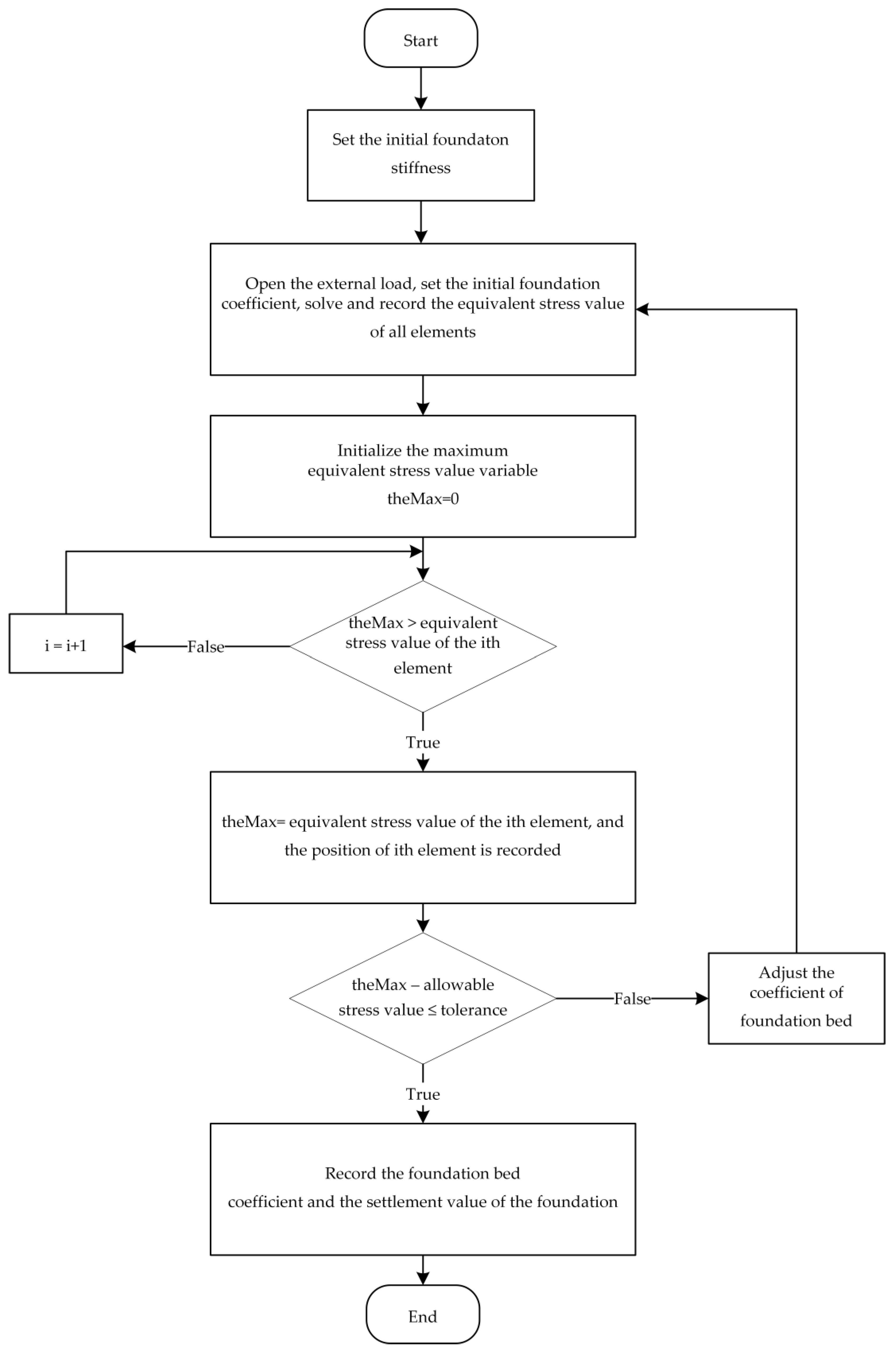
4.1. Critical State Calculation Method

Compile the ANSYS ACT script for automatic trial calculation and separately calculate the basic critical subgrade coefficient K0Cr of the foundation when the von Mises equivalent stress of the bottom plate reaches the yield strength under various working conditions by dichotomy so as to analyze the influence of the distribution of foundation stiffness and seismic intensity on the tank’s bottom plate.
The algorithm flow chart is shown in Figure 8. Detailed steps of the algorithm are as follows:
(1)
The boundary conditions are set according to the heterogeneous stiffness distribution of the foundation;
(2)
Turn on the seismic load and calculate and record the equivalent stress values of all elements at the bottom of the tank according to the Class II site soil;
(3)
Turn off the seismic load, turn on the static load, and calculate and record the equivalent stress values of all elements at the bottom of the tank;
(4)
Add the equivalent stress values at the same position obtained from (2) and (3) to obtain a list of equivalent stresses of all elements of the bottom plate. Use this list to obtain the maximum value of the equivalent stress of the bottom plate and its location;
(5)
Subtract the yield strength at the location of the maximum value from the maximum value to obtain the Mises equivalent stress difference under the current foundation stiffness (Mises Loss, the difference between the maximum value of the Mises equivalent stress of the bottom plate and the allowable stress of the steel at the location);
(6)
Constantly adjust the foundation stiffness K0, and then repeat steps (3) to (5) to make the equivalent stress difference approach 0 MPa, so that the bottom plate just reaches the yield state, that is, the critical state;
(7)
Record the foundation bed coefficient and the maximum foundation settlement when the tank floor reaches the critical state;
(8)
Switch the heterogeneous foundation distribution form until all foundation stiffness distribution forms are calculated.

4.2. Working Condition Design

In order to simulate the foundation with heterogeneous stiffness, the heterogeneous foundation stiffness is abstracted as a function of spatial coordinates through mathematical derivation. For ease of expression, the part with positive x-coordinate of the tank is referred to as “windward side”, and the part with negative x-coordinate is referred to as “leeward side”.
Suppose that the expression of foundation stiffness is
K = K 0 φ r , θ
K—Foundation bed coefficient value at some point in the tank bottom plate (kN/m3);
K0—Basic bed coefficient value of the tank’s bottom plate (kN/m3);
φ—Distribution function of foundation stiffness;
r—Radial coordinates (m);
θ—Circumferential coordinate (°).
Through assumptions and mathematical derivation, the distribution function expressions of seven different forms of uneven foundation are obtained, and the distribution diagram of foundation stiffness is drawn, as shown in Table 4, where R is the radius of the tank, rs is the radius of the round hard object of the foundation, and a is the radial distance between the center of the round hard object and the center of the bottom plate.
Under the condition of heterogeneous foundation stiffness, the critical condition analysis is carried out for the tank with a nominal volume of 20,000 m3, and the most unfavorable combination is made between the seven kinds of heterogeneous foundation conditions and the external effects on the tank.
The tank body is subjected to dead loads, including gravity and static pressure of liquid storage. As shown in Table 5, load combinations are conducted for seven types of uneven distribution of foundation stiffness and five types of seismic conditions, totaling thirty-five conditions, respectively calculating and analyzing the effect of each condition.

5. Analysis of Calculation Results

Through calculation and analysis, the maximum foundation settlement Smax and foundation stiffness K0Cr corresponding to the critical stress of the bottom plate under various working conditions are obtained, as shown in Table 6 and Table 7.
The calculation results show that:
(1)
Under the same heterogeneous foundation, the maximum settlement of the foundation and the critical foundation coefficient increase with the increase in earthquake intensity. The greater the earthquake intensity, the larger the foundation bed coefficient required to ensure that the conical floor is not damaged, and the smaller the maximum settlement of the foundation;
(2)
The critical foundation bed coefficient under each working condition is smaller than the foundation stiffness of silty clay (Approximately 20,000–40,000 kN/m3);
(3)
When there is no seismic action, the minimum critical foundation rigidity value meeting the safe use of the tank is 94 kN/m3, and the corresponding maximum settlement value is 364.34 mm. When the seismic intensity of the tank area is 9°, the maximum critical stiffness of the foundation is 1805 kN/m3, and the corresponding maximum settlement of the foundation is 85.47 mm;
(4)
Under the same seismic intensity, the critical foundation bed coefficient corresponding to the three types of uneven foundations with round hard objects on the windward side is 668 kN/m3, which has a large value and a great influence on the safety of the storage tank.

6. Conclusions

In this paper, the mechanical properties of the inverted cone bottom oil storage tank under the combined action of hydrostatic pressure of the storage fluid, wind load, and seismic load when the foundation stiffness is uneven are determined. Based on the finite element method, this paper takes the 20,000 m3 inverted cone bottom tank in actual engineering as the main modeling object. It assumes seven kinds of heterogeneous foundation conditions, combined with no earthquake or four kinds of different seismic intensities, to make the working condition combination. By constantly adjusting the foundation bed coefficient, finite element calculation and comprehensive analysis are carried out on the corresponding foundation bed coefficient and foundation settlement when the tank bottom reaches the yield strength, and the following conclusions are drawn:
  • The coefficient of the critical foundation bed under each working condition is less than the foundation rigidity of silty clay (Approximately 20,000–40,000 kN/m3). Silty clay foundation can meet the requirements of the tank floor for foundation rigidity;
  • Under the same seismic intensity, the critical foundation bed coefficient corresponding to the three uneven forms with round hard objects on the windward side is larger, so the uneven form of the foundation will have a serious impact on the safety of the storage tank, and the foundation treatment measures should be taken to avoid this situation in practical engineering;
  • Under the same seismic intensity, the uneven form with large foundation stiffness on the windward side is disadvantageous, and the required foundation coefficient is larger;
  • Under the same seismic intensity, the critical foundation bed coefficients calculated by the three heterogeneous forms with large foundation stiffness on the windward side are roughly the same;
  • With the increase of seismic intensity, the critical foundation bed coefficient increases gradually under the same heterogeneous foundation form.

Author Contributions

Writing—original draft preparation, Z.D.; writing—review and editing, H.Q. and Z.C.; validation, Z.D. and H.Q.; methodology, X.H. and Y.W.; software, Z.D. and H.L.; data curation, Z.D. and X.H. All authors have read and agreed to the published version of the manuscript.

Funding

R&D Program of Beijing Municipal Education Commission (grant No. KM202210016010).

Data Availability Statement

Not applicable.

Conflicts of Interest

The authors declare no conflict of interest.

References

  1. Godoy, L.A. Buckling of vertical oil storage steel tanks: Review of static buckling studies. Thin Walled Struct. 2016, 103, 1–21. [Google Scholar] [CrossRef]
  2. Wang, Y.; Leng, M.; Chen, L. Characteristics and construction difficulties of aviation kerosene storage tanks. Oil Gas Storage Transp. 2014, 33, 1353–1358. [Google Scholar]
  3. Shi, L.; Shuai, J.; Wang, X.; Xu, K. Experimental and numerical investigation of stress in a large-scale steel tank with a floating roof. Thin-Walled Struct. 2017, 117, 25–34. [Google Scholar] [CrossRef]
  4. Salem, T.N.; Maaly, H.M.; Abdelbaset, A.M. Dynamic Analysis of Aboveground Steel Storage Tanks Over Stiff Soil. Soil Mech. Found. Eng. 2022, 59, 44–50. [Google Scholar] [CrossRef]
  5. Zhang, H.; El Ansary, A.M.; Zhou, W. Prediction of buckling capacity of liquid-filled steel conical tanks considering field-measured imperfections. Eng. Struct. 2022, 262, 114351. [Google Scholar] [CrossRef]
  6. Burgos, C.A.; Batista-Abreu, J.C.; Calabró, H.D.; Jaca, R.C.; Godoy, L.A. Buckling estimates for oil storage tanks: Effect of simplified modeling of the roof and wind girder. Thin-Walled Struct. 2015, 91, 29–37. [Google Scholar] [CrossRef]
  7. Soni, D.P.; Mistry, B.B.; Panchal, V.R. Double variable frequency pendulum isolator for seismic isolation of liquid storage tanks. Nucl. Eng. Des. 2011, 241, 700–713. [Google Scholar] [CrossRef]
  8. Sahraeian SM, S.; Takemura, J.; Yamada, M.; Seki, S. A Few Critical Aspects to Rational Design of Piled Raft Foundation for Oil Storage Tanks. Geotech. Geol. Eng. Int. J. 2020, 38, 2117–2137. [Google Scholar] [CrossRef]
  9. Gunerathne, S.; Seo, H.; Lawson, W.D.; Jayawickrama, P.W. Analysis of edge-to-center settlement ratio for circular storage tank foundation on elastic soil. Comput. Geotech. 2018, 102, 136–147. [Google Scholar] [CrossRef]
  10. Jing, W.; Wang, J.; Cheng, X. Dynamic responses of oil storage tank considering wind interference effect. Eng. Fail. Anal. 2019, 104, 1053–1063. [Google Scholar] [CrossRef]
  11. Haroun, M.A. Vibration studies and tests of liquid storage tanks. Earthq. Eng. Struct. Dyn. 1983, 11, 179–206. [Google Scholar] [CrossRef]
  12. Cakir, T.; Livaoglu, R. Fast practical analytical model for analysis of backfill-rectangular tank-fluid interaction systems. Soil Dyn. Earthq. Eng. 2012, 37, 24–37. [Google Scholar] [CrossRef]
  13. Durmuş, A.; Livaoglu, R. A simplified 3 D.O.F. model of A FEM model for seismic analysis of a silo containing elastic material accounting for soil–structure interaction. Soil Dyn. Earthq. Eng. 2015, 77, 1–14. [Google Scholar] [CrossRef]
  14. Housner, G.W. Dynamic pressures on accelerated fluid containers. Bull. Seismol. Soc. Am. 1957, 47, 15–35. [Google Scholar] [CrossRef]
  15. Larkin, T. Seismic Response of Liquid Storage Tanks Incorporating Soil Structure Interaction. J. Geotech. Geoenvironmental Eng. 2008, 134, 1804–1814. [Google Scholar] [CrossRef]
  16. Livaoglu, R. Investigation of seismic behavior of fluid–rectangular tank–soil/foundation systems in frequency domain. Soil Dyn. Earthq. Eng. 2008, 28, 132–146. [Google Scholar] [CrossRef]
  17. Van Impe, W.F.; Van Impe, P.O.; Manzotti, A. Pile Design and Group Behaviour: A Case Study of Large Tank Foundations in Soft Soil Conditions. Geotech. Eng. J. SEAGS AGSSEA 2018, 49, 15–29. [Google Scholar]
  18. Teramoto, S.; Niimura, T.; Akutsu, T.; Kimura, M. Evaluation of ultimate behavior of actual large-scale pile group foundation by in-situ lateral loading tests and numerical analysis. Soils Found. 2018, 58, 819–837. [Google Scholar] [CrossRef]
  19. Tarasenko, A.A.; Konovalov, P.A.; Zekhniev, F.F.; Chepur, P.V.; Tarasenko, D.A. Effects of Nonuniform Settlement of the Outer Bottom Perimeter of a Large Tank on its Stress-Strain State. Soil Mech. Found. Eng. 2017, 53, 405–411. [Google Scholar] [CrossRef]
  20. Dimov, L.; Dimov, I.; Bogushevskaya, E. Large Oil Tank Settlement and Tilt During Hydraulic Testing. Soil Mech. Found. Eng. 2017, 54, 192–197. [Google Scholar] [CrossRef]
  21. GB 50011-2010; Code for Seismic Design of Buildings. Ministry of Housing and Urban-Rural Development of the People’s Republic of China: Beijing, China, 2010.
  22. GB 50191-2012; Code for Seismic Design of Special Structures. Ministry of Housing and Urban-Rural Development of the People’s Republic of China: Beijing, China, 2012.
  23. GB 50009-2012; Load Code for the Design of Building Structures. Ministry of Housing and Urban-Rural Development of the People’s Republic of China: Beijing, China, 2012.
Figure 1. Forms of vertical tank bottoms.
Buildings 13 01720 g001
Figure 2. Vertical section of the model.
Buildings 13 01720 g002
Figure 3. Meshing of the model.
Buildings 13 01720 g003
Figure 4. Schematic diagram of inertial force calculation.
Buildings 13 01720 g004
Figure 5. Schematic diagram of liquid inertia additional pressure on the tank wall.
Buildings 13 01720 g005
Figure 6. Wind load coefficient. (a) Coefficient curve of wind pressure variation with height; (b) Shape coefficient curve of tank top wind load; (c) Shape coefficient curve of wind load on tank walls.
Buildings 13 01720 g006aBuildings 13 01720 g006b
Figure 7. Schematic diagram of boundary conditions at node i on the tank bottom. K0i—Foundation bed coefficient at node i (N/mm3); Kix—The stiffness of the x-direction elastic support at node i (N/mm); Kiy—The stiffness of the y-direction elastic support at node i (N/mm); Kiz—The stiffness of the z-direction elastic support at node i (N/mm); ν—Lateral pressure coefficient of foundation; lx—Length of elastic support in x-direction (mm); ly—Length of elastic support in y-direction (mm); lz—Length of elastic support in z-direction (mm); Ai—Shared area of node i of the tank bottom plate (mm2); E—Elastic modulus of foundation (MPa).
Buildings 13 01720 g007
Figure 8. Algorithm for finding critical state of bottom stress under uneven foundation.
Buildings 13 01720 g008
Table 1. Material parameter values.
ParameterValue
The density of steel/kg·m−37850
Elastic modulus of steel/MPa2 × 105
Poisson’s ratio of steel0.3
Standard value of yield stress of tank steel/MPa345
Elastic modulus of sand cushion/MPa30
Sand cushion Poisson’s ratio0.32
Elastic modulus of ring wall foundation/MPa3.25 × 104
Poisson’s ratio of ring wall foundation0.2
Table 3. Seismic design parameters for storage tanks.
Site Soil TypeII
The seismic intensity
Design seismic groupingThe first group
Basic seismic acceleration for design0.05 g
Table 4. Distribution forms of foundation stiffness.
Serial
Number
Distribution Forms of
Foundation Stiffness
Schematic DiagramFunctional Expression
Foundation form 1The foundation stiffness is larger in the central circular areaBuildings 13 01720 i001 φ r ,   θ = ( 2 r R )
Foundation form 2The foundation stiffness in the 1/2 circle area on the windward side is largerBuildings 13 01720 i002 φ r ,   θ = e 2 90 θ 2 r R + 1
Foundation form 3The foundation stiffness in the 1/3 circle area on the windward side is largerBuildings 13 01720 i003 φ r ,   θ = e 2 60 θ 2 r R + 1
Foundation form 4The foundation stiffness in the 1/4 circle area on the windward side is largerBuildings 13 01720 i004 φ r ,   θ = e 2 45 θ 2 r R + 1
Foundation form 5Round hard object with a radius of 0.5 m in the centerBuildings 13 01720 i005 φ r ,   θ = 1 + 1 1 + e 0.1 ( r r s )
Foundation form 6Round hard object with a radius of 0.5 is a = R/2 away from the center on the windward sideBuildings 13 01720 i006 φ r ,   θ = 1 + 1 1 + e 0.1 ( a 2 + r 2 2 a r cos θ r s )
Foundation form 7The windward side has a round hard object with a radius of 0.5 mBuildings 13 01720 i007 φ r ,   θ = 1 + 1 1 + e 0.1 ( R 2 + r 2 2 R r cos θ r s )
Table 5. The load combination of each working condition.
Uneven Form of FoundationDead Load + Wind Load
Foundation form 1Combination of 1.1Combination of 1.2Combination of 1.3Combination of 1.4Combination of 1.5
Foundation form 2Combination of 2.1Combination of 2.2Combination of 2.3Combination of 2.4Combination of 2.5
Foundation form 3Combination of 3.1Combination of 3.2Combination of 3.3Combination of 3.4Combination of 3.5
Foundation form 4Combination of 4.1Combination of 4.2Combination of 4.3Combination of 4.4Combination of 4.5
Foundation form 5Combination of 5.1Combination of 5.2Combination of 5.3Combination of 5.4Combination of 5.5
Foundation form 6Combination of 6.1Combination of 6.2Combination of 6.3Combination of 6.4Combination of 6.5
Foundation form 7Combination of 7.1Combination of 7.2Combination of 7.3Combination of 7.4Combination of 7.5
Table 6. The maximum foundation settlement Smax (Unit: mm).
Uneven Form of FoundationDead Load + Wind Load
Foundation form 1254.54356.64343.73165.4585.47
Foundation form 2364.34360.75347.77179.7689.30
Foundation form 3319.30359.90347.22179.7588.96
Foundation form 4295.41360.15347.41180.3588.87
Foundation form 5230.01300.43282.7106.2430.96
Foundation form 6230.02300.44282.9106.2530.97
Foundation form 7230.03300.42282.5106.2430.96
Table 7. Critical stiffness K0Cr of the storage tank under various working conditions (Unit: kN/m3).
Uneven Form of FoundationDead Load + Wind Load
Foundation form 11321081414991805
Foundation form 2941181494621686
Foundation form 31111171484621701
Foundation form 41211161474591707
Foundation form 566863565221683328
Foundation form 666863565221683328
Foundation form 766863565221683328
Disclaimer/Publisher’s Note: The statements, opinions and data contained in all publications are solely those of the individual author(s) and contributor(s) and not of MDPI and/or the editor(s). MDPI and/or the editor(s) disclaim responsibility for any injury to people or property resulting from any ideas, methods, instructions or products referred to in the content.

