Article

Experimental Investigations of the Seismic Response of a Large Underground Structure at a Soft Loess Site

1
School of Civil Engineering, Xi’an University of Architecture and Technology, Xi’an 710055, China
2
Key Lab of Structural Engineering and Earthquake Resistance, Ministry of Education (XAUAT), Xi’an 710055, China
3
Shaanxi Academy of Building Research Co., Ltd., Xi’an 710082, China
4
UniSA STEM, University of South Australia, Adelaide 5000, Australia
*
Authors to whom correspondence should be addressed.
Buildings 2023, 13(7), 1710; https://doi.org/10.3390/buildings13071710
Submission received: 1 June 2023 / Revised: 29 June 2023 / Accepted: 1 July 2023 / Published: 4 July 2023

Abstract

:
Based on an underground structure located at a soft loess site in Xi’an as the engineering background, this paper investigated a seismic response and damage model of subway stations at a soft loess site using a large-scale shaking table test, considering the different characteristics of ground motions. The quantitative analysis of the acceleration response and the seismic subsidence of the soft loess site were subjected to different earthquake excitations; based on the experimental results and the corresponding analysis, the development and distribution of seismic structural damage were studied, and the damage mechanism of underground structures in a soft loess area under a strong earthquake was explored. The results indicate that the peak accelerations of the site soil first remained unchanged then increased significantly along the soil height, and the amplification effect of the acceleration response was the most significant at the soil surface. The soft loess soil underwent significant subsidence, and the underground structure was raised compared to both sides of the cover soil; the collapsibility of the soft loess soil was sensitive to strong earthquakes with vertical components. The underground structures in soft loess suffered heavy damage, which rapidly entered the elastic–plastic stage. The composite effect of the collapsibility and vertical seismic excitation impaired the load-carrying capacity of the middle columns, and the strong horizontal seismic excitation enlarged the lateral force and accelerated structural damage development; the underground structure reached failure when plastic damage expended most of the middle columns and structural joints. These results are significant for the seismic design of underground structures in adverse soil conditions.

1. Introduction

With rapid urbanization, the contradiction between a high-density population and limited ground space is becoming increasingly prominent. Accordingly, lots of attention has been paid to underground space to relieve the pressure on the limited urban space [1,2,3]. Subway stations, as a kind of common underground structure in cities, play an important role in the operation safety of urban rail transit [4]. To guarantee smooth traffic flows and the demand for crowd gathering, subway stations possess large spaces, which could be defined as large underground structures. It is unavoidable to build large underground structures in seismic areas with adverse geological conditions [5,6,7,8]. The complexity of the soil–structure interactions (SSIs) at adverse geological sites makes the seismic responses of underground structures very distinct from their regular responses [9]. Therefore, it is urgent to obtain the damage mechanism of large underground structures subjected to strong earthquakes.
As a common geologic condition, soft loess is causing widespread natural hazard around the world [10,11,12], which has particular movement characteristics and seismic properties [13,14]. Among them, the main characteristic of its movement is vertical subsidence, which leads to varying degrees of continuous damage to many buildings and structures [15,16]. Loess subsidence is related to groundwater activity, and the structural damage could be reduced by controlling groundwater extraction [17,18], while the seismic effect of soft loess on structural damage cannot be eliminated [19], which should be paid great attention by engineers and scholars.
Numerical analyses have been widely used to investigate the seismic behaviors and damage mechanisms of engineering structures, considering SSI effects. Maleska and Beben [20] analyzed the impact of soil cover depth on large-span CSP bridges under seismic excitation with the FEA numerical program; it was found that the reaction of the bridge did not always increase with an increasing depth of soil cover. Forcellini [21] assessed the seismic vulnerability of a 20-floor building, with consideration of SSI effects, and he found that neglecting SSI effects would underestimate the seismic damage for structural and non-structural members. Jalali et al. [22] investigated the seismic performance of a 5-story shear building with semi-actively controlled MR dampers, considering SSI effects under different earthquake records; it was concluded that the seismic responses of structures in soft soil conditions were greater than those in other soil conditions (i.e., fixed-base and dense, medium, and soft soil support conditions). Seismic studies of underground structures were also carried out by some scholars. Huo et al. [23] and Parra-Montesinos et al. [24] conducted dynamic analyses to understand the influence of a dynamic structure–soil interaction on the seismic behavior of underground tunnels; however, the plastic damage in the underground structures could not be simulated because the underground structures were modeled as elastic materials. Li and Chen [25] and Ma et al. [26,27] developed 3D FE models of the underground structures to analyze the damage pattern of Dakai station under an earthquake, considering the elastoplastic material properties of the concrete and steel rebars. It could be concluded that the damage pattern of Dakai station showed an “M” mode, which was due to the collapse of the center columns.
In the past two decades, many researchers have conducted scale-model tests of the seismic responses of underground structures in difficult site conditions. Iwatate et al. [28] and Ohtomo et al. [29] carried out dynamic tests on an underground station and a pipeline, and a deformation model and dynamic characteristics were obtained. Chen et al. [30,31] studied the seismic behavior and seismic damage mechanism of a utility tunnel subjected to non-uniform earthquake excitations by large-scale shaking table tests. Chen et al. [32,33] and Zhuang et al. [34,35] conducted experimental and numerical studies on the dynamic responses and failure mechanisms of underground structures in soft and liquefiable sites. It was derived that the seismic performances of the underground structures were substantially dominated by the deformation of the surrounding soils; the underground structures in soft or liquefiable soils experienced greater damage than those in soils without adverse geological conditions, which was due to the larger deformation of the soils. However, the seismic codes of underground structures in China are unsuitable for assessing the seismic performances of large underground structures in adverse geological conditions under strong earthquakes [36]. In summary, the studies of the seismic responses of underground structures in adverse site conditions were generally focused on liquefiable and soft sites. Seismic research on underground structures at soft loess sites is still in its infancy [37], and the seismic damage mechanism of underground structures in this condition under strong earthquakes is not clear. Hence, it is crucial to investigate the seismic responses of underground structures at soft loess sites.
This paper presents an experimental study on the underground structures at a soft loess site. The seismic responses of the site’s soil and underground structure were investigated, and the damage mechanism of the underground structures at the soft loess site under strong earthquakes was explored. The conclusions could provide the scientific basis for evaluating the seismic performances of large underground structures in adverse geological conditions, which would provide a reference for the seismic design of underground structures.

2. Test Design

2.1. Test Setup

The test model was designed and fabricated according to a part of the actual project of the Kangfu Road subway station. Shaking table tests were conducted in the Key Lab of Structure Engineering and Earthquake Resistance, School of Civil Engineering, Xi’an University of Architecture & Technology.
The shaking table tests were performed on a shaking table with dimensions of 4.1 m × 4.1 m in plane and a maximum bearing capacity of 25 tons. In addition, seismic loads in three directions could be applied simultaneously by the shaking table system, where the maximum accelerations in the longitudinal direction (X), transverse direction (Y), and vertical direction (Z) were 1.5 g, 1.0 g, and 1.0 g, respectively. Meanwhile, a flexible model box composed of 14 layers of rectangular steel tubes was adopted as the SSI system container for the test (see Figure 1), which could achieve the shear deformation for site soils subjected to earthquakes [38]. A high-damping rubber membrane and a polystyrene foam board were arranged on the inwall of the soil container to reduce the boundary effect. Additionally, several wood blocks were posted on the bottom of the soil container to increase the friction between the model soil and the container. The dimensions of the container were 3.0 m in length, 1.5 m in width, and 1.5 m in height.

2.2. Similarity Law and Model Construction

Based on the Buckingham π theorem, the similarity criteria for the test model were determined. Among them, the geometry, the dynamic shearing modulus, and the acceleration were selected as the basic parameters, and other similarities were deduced, as summarized in Table 1. The underground structure model was a three-story frame structure of the Kangfu Road project in Xi’an, which is located at a soft loess site. The subway station structure has a width of 20.5 m and a height of 13.21 m. The interval distances of the middle columns are 5.2 m and 9.8 m in the width and longitudinal directions. The groundwater at the site was determined to be phreatic water by drilling, and its activity was relatively stable. The buried depth of the stable water level varied from 4.80 to 5.00 m, and the groundwater activity was neglected due to the research purpose. Based on the similarity coefficient of the length, the width, height, and length of the model structure were determined to be 513 mm, 330 mm, and 1040 mm, respectively. A cross-section of the model is shown in Figure 2.
To meet the requirements of the similarity relations in the test, micro-particle concrete and zinc-coated wires were used as the fabrication materials of the underground structure model. The micro-particle concrete consisted of cement, water, coarse sand, and lime, with a mass ratio of 1:1.2:5:0.5, and samples with dimensions of 70.7 mm × 70.7 mm × 70.7 mm and 70.7 mm × 70.7 mm × 210 mm were fabricated for the compressive test and elastic modulus test, respectively. Accordingly, the compressive strength and elastic modulus of the micro-particle concrete were 8.3 MPa and 6.2 GPa, and the tensile strength could be estimated to be 1/10 of the compressive strength. For the zinc-coated wires, wires with diameters of 0.7–1.2 mm were used for beams and columns, and those with a diameter of 0.7 mm were used for plates and side walls; after material testing, the tensile yield strength of the zinc-coated wires was 1190 MPa, and the corresponding elastic modulus was 200 GPa. Figure 3 depicts the fabrication procedure of the model station. It was noted that a foam board with a thickness of 2 mm was used to seal the model structure to prevent the inflow of soil and water during the test. This was the same as the fabrication method in reference [39].
Meanwhile, a mixture of loess collected from the prototype site and sawdust was selected as the material of the model soil, and the dynamic shearing modulus of the model soil was determined using the relative stiffness for a study on the soil–structure interaction [36]. The model soil was designed with a 1280 mm thick loess layer, and the subway station was placed in the loess layer with around 120 mm of plain fill above the station, as shown in Figure 4. It was noted that the dimensions of the SSI system were scaled due to the size of the soil box and the bearing capacity of the shaking table. An open-cut method was adopted for the model station, which was fully consistent with the actual situation. Consequently, the structural responses for the prototype scale could be deduced using the similarity relationship. Before the test, a series of geotechnical tests on different soil samples were conducted to obtain the target parameters, and the designed compaction and moisture content were determined. During the fabrication of the model soil, the loess soil was filled and compacted layer by layer, and every compacted layer was taken as 20 cm. The mechanical properties of the loess soil for the prototype and the model sites were obtained via resonant column and dynamic triaxial tests, and the main material properties are listed in Table 2.

2.3. Instrumentation

The seismic response characteristics of the underground structure at the soft loess site were measured with different sensors consisting of accelerometers, displacement meters, and strain gauges. Among these sensors, accelerometers were used to record the acceleration response of the subway station and the acceleration response of the soil at the soft loess site. The concrete strain of the sidewalls, middle columns, and slabs was measured with 32 strain gauges. The displacement meters were used to analyze the horizontal and vertical displacement of the model soil. The sensor layout is shown in Figure 5.

2.4. Loading Protocol

To consider the effects of different frequency spectrum characteristics of ground motions on the seismic response of the underground structure at the soft loess site, three ground motions were used as seismic excitation inputs in the test: the Jiangyou ground motion record (Wenchuan earthquake on 12 May 2008, Sichuan, China, Jiangyou Station), the El Centro ground motion record (Imperial Valley earthquake on 18 May 1940, CA, USA, El Centro Array #9 Station), and Xi’an artificial motion (synthesized based on the site condition for the prototype underground structure). The acceleration histories and Fourier spectra of the unscaled ground motions are shown in Figure 6.
Table 3 lists the loading cases. According to the similitude relation of the time and acceleration (see Table 1), these ground motions were scaled in amplitude and duration. The earthquake intensities for the test varied from 0.2 g to 1.2 g (e.g., PGA varied from 0.1 g to 0.6 g on the prototype scale), and the effect of the vertical earthquake component was considered in cases with strong earthquakes (e.g., PGA = 1.2 g on the model scale).

3. Test Results and Interpretation

3.1. Acceleration Response of the Site Soil

The acceleration response of the loess soil with the soil depth was investigated through the peak accelerations of AS1, AS2, AS3, and AS4 for different input waves, as shown in Figure 7 and Figure 8. For input waves at a low PGA (e.g., 0.2 g), the difference in the peak acceleration of the site soil along the depth was not obvious. For input waves at a higher PGA (e.g., 0.4 g), the peak accelerations first remained unchanged then increased significantly along the height of model’s soil. With the increasing PGAs, the peak accelerations first decreased slowly then increased significantly along the height of model’s soil. It was noted that the accelerations of points below the soil surface were less than or close to the input PGAs, and those of points measured at the soil surface were greater than the input PGAs and significantly greater than other measuring points, which indicated that the soil’s acceleration amplification effect was the most significant at the soil surface; meanwhile, the location of the model station had an obvious influence on acceleration responses of the site’s soil. These results were similar to the findings of previous experimental studies on soft soils’ acceleration responses [36].
In addition, the change trend of the soil’s peak accelerations with the depth was basically consistent with and without considering the vertical earthquake component, and the acceleration response of each measuring point in the loess soil was more intense when the effect of the vertical earthquake component was considered.

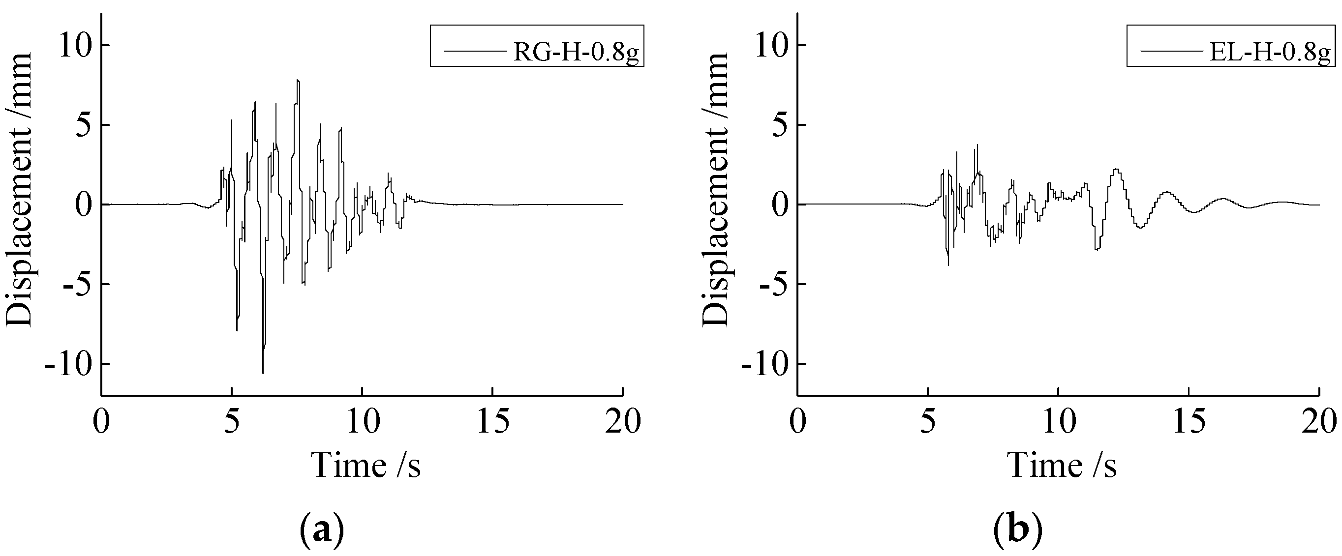
3.2. Displacement Response of Model Soil

The lateral deformation of the model soil was investigated by comparing the peak displacement values obtained at measuring points D1, D2, and D3 for different input waves, as depicted in Figure 9 and Figure 10. The peak lateral displacement of the site soil along the height was basically unchanged when the PGA of the input waves was low (e.g., 0.2 g and 0.4 g). As the input PGAs increased, the peak lateral displacement of the model soil increased with the increase in model soil height. For cases with high PGAs, the peak lateral displacement of each measuring point in the model box increased significantly. It was also noted that the site soil exhibited a shear deformation along the height direction, indicating that the model soil box used in this test could simulate the shear deformation of the site soil.

3.3. Subsidence Analysis of Model Soil

The seismic subsidence of the loess soil was investigated by comparing the peak subsidence values obtained at measuring points J1, J2, and J3 for various loading conditions, as shown in Figure 11. For input waves at low PGAs (e.g., 0.2 g), the peak values of these measuring points were relatively small, and the differences in the peak subsidence values among the different measuring points were not obvious, indicating that the seismic subsidence of the soft loess soil was not obvious. As the PGAs of the input waves increased, the peak subsidence values increased generally, and the differences in the values among the different measuring points became obvious, which showed a lower value at the point above the underground structure and higher values at other points. This indicated that the model soil underwent significant subsidence, and the underground structure was raised compared to both sides of the cover soil. Similar trends could be observed in experimental studies on seismic-induced ground surface settlement performed by Tang et al. [36] and Chen et al. [5]. The settlement values in this test were significantly less than the soil’s depth, which indicated that the changes in the soil’s density could be negligible. As for cases of bidirectional input motions with a horizontal PGA of 1.2 g, the subsidence values were significantly enlarged, and the differences in subsidence values among the different measuring points were much larger compared to cases of single horizontal input motions. This demonstrated that the collapsibility of the soft loess soil was sensitive to strong earthquakes with vertical components.

3.4. Acceleration Response of Model Station

Figure 12 presents the peak structural acceleration along the height for the underground structure at the soft loess site, including cases with and without the vertical earthquake component. Figure 13 gives the acceleration histories obtained at the top floor under earthquake excitations. For input motions with low PGAs (e.g., 0.2 g and 0.4 g), the peak structural accelerations increased with the height of the subway station, which showed an inverted triangle shape. For input waves with a high PGA (e.g., 0.8 g), the peak accelerations of the subway station decreased first and then increased along the station height, which showed a k-shape distribution. Overall, the underground structure moved along with the surrounding soil subjected to earthquakes with low PGAs, causing the inverted triangle shape for the deformation of the underground structure due to the shear deformation of the surrounding soil. As for cases with high PGAs, collisions and separations would occur at the interaction between the underground structure and the surrounding soil; the distribution of the peak structural accelerations along the height was related to the stiffness distribution of the underground structure at some moments, and the stiffness of the station was larger in the top slab and the bottom slab, resulting in a k-shape distribution, as mentioned. These trends were in good agreement with those in reference [40], which indicated that it was easy to cause the incongruous movement of underground structures in soft loess soil.
It can also be seen that the peak accelerations of the station were obviously amplified when the vertical earthquake was considered by comparing the cases with and without the vertical earthquake component. The vertical earthquake aggravated the nonlinearity and collapsibility of loess soil, and the void area appeared easily, resulting in a weaker SSI interaction.

3.5. Structural Strain Response

Figure 14 depicts the peak tensile strain of the structural components for the model station subjected to Jiangyou motions, and the locations where the maximum strain occurred are marked in red. It was noted that the limited tensile strain of the micro-particles was about 95 × 10−6, which was also adopted in reference [38]. For horizontal input motions with a low PGA (e.g., 0.2 g), the maximum strain occurred in the bottom beam–middle column joint, which was obviously larger than the strain in other parts; the peak strain of the measuring points did not exceed the limited strain, indicating that the underground structure was in the elastic working state. As the input PGAs increased (e.g., PGA = 0.4 g and PGA = 0.8 g), the peak tensile strain at the bottom beam–column joints (S5 and S8) and middle plate–column joints (S22) exceed the limited tensile strain, and plastic deformation occurred on most areas in the middle columns, while the tensile damage on the plates and sidewalls was insignificant. For horizontal input motions with PGA = 1.2 g, the seismic damage dramatically developed in different structural components, and the peak tensile strain occurred at the plate near the plate–side wall joint (S20). The plate–column joints (S22, S27, and S30) and the beam–column joints (S5, S8, and S13) all exceeded the limited tensile strain. For bidirectional input motions with horizontal PGA = 1.2 g, plastic damage developed in most areas in the model structure, including the plates, the plate–column joints, and the beam–column joints.
Generally, some experimental results on plastic damage distribution were similar to the damage distribution of the Daikai station [28]. It was noted that severe failure was observed on the central columns of the Daikai station, while the structural members of the underground structures in the adverse site soil suffered more severe damage than those in common site soil under the same earthquake excitation, and the underground structure rapidly failed in soft loess soil.

3.6. Failure Mechanism Analysis

According to the experimental analysis, the damage development process of the underground structure in the soft loess area under a strong earthquake with horizontal and vertical components is shown in Figure 15. The seismic damage appeared continuously in weak structural members or regions with high stress. Then, the underground structure rapidly entered into the elastoplastic stage. First, some plastic damage appeared in the middle plate–bottom beam joints and middle plate–middle column joints. Subsequently, the damaged regions developed continuously: the plastic damage appeared successively in the top plate–top beam joints and middle plate–sidewall joints. Finally, most of the structural members were damaged, and the structure was destroyed.
It was found that the seismic failure of the underground structures in the soft loess region could be concluded: (1) The underground structures in soft loess suffered heavy damage, especially the middle columns, which was due to the obvious nonlinearity and collapsibility of loess soil under a strong earthquake. (2) They were prone to serious damage in the transfer areas between the vertical components and horizontal components because the structural force was loaded heavily in the joints under seismic excitation. (3) The composite effect of the collapsibility and vertical seismic excitation impaired the load-carrying capacity of the middle columns, and the strong horizontal seismic excitation enlarged the lateral force and accelerated the structural damage development; the underground structure reached failure when the plastic damage expended most of the middle columns and structural joints. Therefore, it is recommended to adopt the necessary reinforcement measures on all the structural joints and middle columns.

4. Conclusions

In this paper, the seismic behavior of an underground station in soft loess that is subjected to strong earthquake excitations was explored by conducting shaking table tests on scaled SSI models. Emphasis was placed on the seismic response characteristics of loess soil and the influence of the soft loess soil conditions on the seismic response and damage model of the underground structure. Conclusions were drawn as follows:
(1)
When the PGA of the input motions was low, the differences in the peak accelerations of the site soil along the height were not obvious. As the PGA of the earthquake waves increased, the peak accelerations first remained unchanged then increased significantly along the soil height, which indicated that the location of the model station had an obvious influence on the acceleration responses of the site soil.
(2)
Under strong earthquakes, the soft loess soil underwent significant subsidence, and the underground structure was raised compared to both sides of the cover soil. The settlement values in this test were significantly less than the soil’s depth, which indicated that the changes in the soil’s density could be negligible. Additionally, the collapsibility of the soft loess soil was sensitive to strong earthquakes with vertical components.
(3)
The subway station moved along with the surrounding soil under earthquakes with low seismic intensities. As for cases with high seismic intensities or cases with vertical earthquakes, the peak accelerations of the subway station were obviously increased, which indicated that it was easy to cause the incongruous movement of underground structures in soft loess soil because the void area between the underground structure and the surrounding soils appeared easily, which weakened the underground structure–soil interaction.
(4)
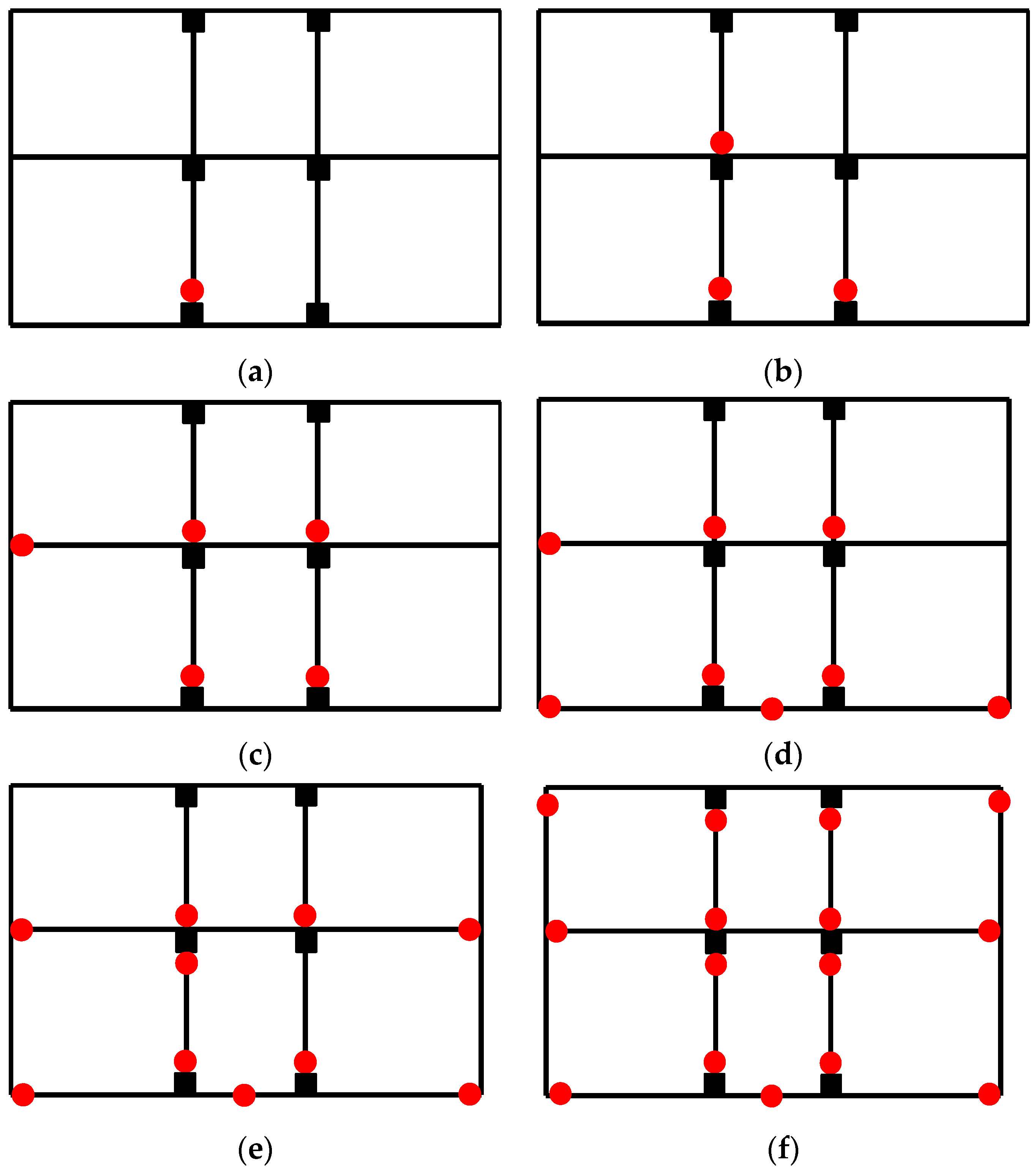
Under strong earthquakes, the seismic damage of the underground structure in the soft loess area appeared successively in the middle columns and structural joints (e.g., the plate–column and beam–column joints), and the structure rapidly entered the elastic–plastic stage.
(5)
The composite effect of the collapsibility and vertical seismic excitation impaired the load-carrying capacity of the middle columns, and the strong horizontal seismic excitation enlarged the lateral force and accelerated the structural damage development; the underground structure reached failure when the plastic damage expended most of the middle columns and structural joints.
As a consequence, this paper shows that an adverse site condition has a significant impact on the seismic damage of underground structures, and necessary measures need to be proposed to improve the seismic performances of underground structures (i.e., isolation and reinforcement measures), which will form the subject of further research.

Author Contributions

Conceptualization, X.C. and C.R.; methodology, X.C. and Y.L.; investigation, X.C. and C.R.; resources, X.C. and C.R.; data curation, C.R.; writing—original draft preparation, X.C. and C.R.; writing—review and editing, Z.X. and Y.L.; visualization, X.C.; supervision, Z.X. and X.C.; project administration, X.C. and Z.X.; funding acquisition, Z.X. and X.C. All authors have read and agreed to the published version of the manuscript.

Funding

This research was funded by the China Postdoctoral Science Foundation (No. 2021M693876) and the Natural Science Foundation of Shaanxi Province (No. 2023-YBSF-545).

Data Availability Statement

Data will be made available on request.

Acknowledgments

The support of the China Postdoctoral Science Foundation and the Natural Science Foundation of Shaanxi Province is highly appreciated.

Conflicts of Interest

The authors declare no conflict of interest.

References

  1. Huang, B.T.; Zhu, J.X.; Weng, K.F.; Huang, J.Q.; Dai, J.G. Prefabricated UHPC-concrete-ECC underground utility tunnel reinforced by perforated steel plate: Experimental and numerical investigations. Case Stud. Constr. Mater. 2022, 16, e00856. [Google Scholar] [CrossRef]
  2. Kishii, T. Utilization of underground space in Japan. Tunn. Undergr. Space Technol. 2016, 55, 320–323. [Google Scholar] [CrossRef]
  3. Broere, W. Urban underground space: Solving the problems of today’s cities. Tunn. Undergr. Space Technol. 2016, 55, 245–248. [Google Scholar] [CrossRef] [Green Version]
  4. Li, A.G.; Ma, J.Y.; Cui, H.H.; Zhang, X.; Zhang, W.R.; Guo, Y.Z. Relative importance of certain factors affecting the thermal environment in subway stations based on field and orthogonal experiments. Sustain. Cities Soc. 2020, 56, 102107. [Google Scholar]
  5. Chen, S.; Tang, B.Z.; Zhao, K.; Li, X.J.; Zhuang, H.Y. Seismic response of irregular underground structures under adverse soil conditions using shaking table tests. Tunn. Undergr. Space Technol. 2020, 95, 103145. [Google Scholar] [CrossRef]
  6. Chen, X.; Xiong, Z.M.; Zhuge, Y.; Liu, Y. Numerical analysis on the seismic performance of subway station in ground crack area. Tunn. Undergr. Space Technol. 2023, 134, 105012. [Google Scholar] [CrossRef]
  7. Yuan, B.X.; Chen, W.J.; Zhao, J.; Li, L.J.; Liu, F.; Guo, Y.C.; Zhang, B. Addition of alkaline solutions and fibers for the reinforcement of kaolinite-containing granite residual soil. Appl. Clay Sci. 2022, 228, 106644. [Google Scholar] [CrossRef]
  8. Yuan, B.X.; Chen, W.J.; Li, Z.H.; Zhao, J.; Luo, Q.Z.; Chen, W.W.; Chen, T.Y. Sustainability of the polymer SH reinforced recycled granite residual soil: Properties, physicochemical mechanism, and applications. J. Soils Sediments 2023, 23, 246–262. [Google Scholar] [CrossRef]
  9. Miao, Y.; Zhong, Y.; Ruan, B.; Cheng, K.; Wang, G.B. Seismic response of a subway station in soft soil considering the structure-soil-structure interaction. Tunn. Undergr. Space Technol. 2020, 106, 103629. [Google Scholar] [CrossRef]
  10. Zhang, Z.Z.; Wang, L.M. Geological disasters in loess areas during the 1920 Haiyuan Earthquake, China. GeoJournal 1995, 36, 269–274. [Google Scholar] [CrossRef] [Green Version]
  11. Rogers, C.; Dijkstra, T.; Smalley, I. Hydroconsolidation and subsidence of loess: Studies from China, Russia, North America and Europe: In memory of Jan Sajgalik. Eng. Geol. 1994, 37, 83–113. [Google Scholar] [CrossRef]
  12. Zhang, H.X.; Zeng, R.Q.; Zhang, Y.; Zhao, S.F.; Meng, X.M.; Li, Y.X.; Liu, W.C.; Meng, X.P.; Yang, Y.P. Subsidence monitoring and influencing factor analysis of mountain excavation and valley infilling on the Chinese Loess Plateau: A case study of Yan’an New District. Eng. Geol. 2022, 297, 106482. [Google Scholar] [CrossRef]
  13. Qiu, J.L.; Wang, X.L.; Lai, J.X.; Zhang, Q.; Wang, J.B. Response characteristics and preventions for seismic subsidence of loess in Northwest China. Nat. Hazards 2018, 92, 1909–1935. [Google Scholar] [CrossRef]
  14. Yao, W.; Li, X.a.; Zhang, N.; Ren, Y.B.; Shi, J.F.; Zhang, C.; Xue, Q.; Hao, Z.T. A Feasible Method for Evaluating the Uniformity of Remolded Loess Samples with Shear Strength. Buildings 2023, 13, 145. [Google Scholar] [CrossRef]
  15. Xie, B.L.; Zhang, W.Y.; Sun, X.L.; Huang, Y.L.; Liu, L.Q. Experimental Study on the Effects of Freeze–Thaw Cycles on Strength and Microstructure of Xining Region Loess in China. Buildings 2022, 12, 795. [Google Scholar] [CrossRef]
  16. Li, H.; Ma, E.L.; Lai, J.X.; Wang, L.X.; Xu, S.S.; Wang, K.; Liu, T. Tunnelling-induced settlement and treatment techniques for a loess metro in Xi’an. Adv. Civ. Eng. 2020, 2020, 1854813. [Google Scholar] [CrossRef]
  17. Mosallam, A.S.; Bayraktar, A.; Elmikawi, M.; Pul, S.; Adanur, S. Polymer Composites in Construction: An Overview; UC Irvine: Irvine, CA, USA, 2021. [Google Scholar]
  18. Evstatiev, D. Design and treatment of loess bases in Bulgaria. In Genesis and Properties of Collapsible Soils; Springer: Dordrecht, The Netherlands, 1995; pp. 375–382. [Google Scholar]
  19. Olimpiev, D.; Makhmudov, A.; Mamazhanov, M.; Shakirov, B.; Sattiev, Y. Stress-strain state dams on a loess subsidence base. IOP Conf. Ser. Earth Environ. Sci. 2022, 954, 012002. [Google Scholar] [CrossRef]
  20. Maleska, T.; Beben, D. Effect of the soil cover depth on the seismic response in a large-span thin-walled corrugated steel plate bridge. Soil Dyn. Earthq. Eng. 2023, 166, 107744. [Google Scholar] [CrossRef]
  21. Forcellini, D. Seismic fragility of tall buildings considering soil structure interaction (SSI) effects. Structures 2022, 45, 999–1011. [Google Scholar] [CrossRef]
  22. Jalali, H.H.; Farzam, M.F.; Gavgani, S.A.M.; Bekdaş, G. Semi-active control of buildings using different control algorithms considering SSI. J. Build. Eng. 2023, 67, 105956. [Google Scholar] [CrossRef]
  23. Huo, H.; Bobet, A.; Fernández, G.; Ramirez, J. Load transfer mechanisms between underground structure and surrounding ground: Evaluation of the failure of the Daikai station. J. Geotech. Geoenviron. Eng. 2005, 131, 1522–1533. [Google Scholar] [CrossRef]
  24. Parra-Montesinos, G.J.; Bobet, A.; Ramirez, J.A. Evaluation of soil-structure interaction and structural collapse in Daikai subway station during Kobe earthquake. ACI Mater. J. 2006, 103, 113–122. [Google Scholar]
  25. Li, W.T.; Chen, Q.J. Seismic performance and failure mechanism of a subway station based on nonlinear finite element analysis. KSCE J. Civ. Eng. 2018, 22, 765–776. [Google Scholar] [CrossRef]
  26. Ma, C.; Lu, D.C.; Du, X.L.; Qi, C.Z. Effect of buried depth on seismic response of rectangular underground structures considering the influence of ground loss. Soil Dyn. Earthq. Eng. 2018, 106, 278–297. [Google Scholar] [CrossRef]
  27. Ma, C.; Lu, D.C.; Du, X.L.; Qi, C.Z.; Zhang, X.Y. Structural components functionalities and failure mechanism of rectangular underground structures during earthquakes. Soil Dyn. Earthq. Eng. 2019, 119, 265–280. [Google Scholar] [CrossRef]
  28. Iwatate, T.; Kobayashi, Y.; Kusu, H.; Rin, K. Investigation and shaking table tests of subway structures of the Hyogoken-Nanbu earthquake. In Proceedings of the 12th World Conference on Earthquake Engineering, Auckland, New Zeland, 30 January–4 February 2000; pp. 1043–1051. [Google Scholar]
  29. Ohtomo, K.; Suehiro, T.; Kawai, T.; Kanaya, K. Research on streamlining seismic safety evaluation of underground reinforced concrete duct-type structures in nuclear power stations.-Part-2. Experimental aspects of laminar shear sand box excitation tests with embedded RC models. In Proceedings of the SMiRT 16, Washington DC, USA, 12–17 August 2001. [Google Scholar]
  30. Chen, J.; Shi, X.J.; Li, J. Shaking table test of utility tunnel under non-uniform earthquake wave excitation. Soil Dyn. Earthq. Eng. 2010, 30, 1400–1416. [Google Scholar] [CrossRef]
  31. Chen, J.; Jiang, L.Z.; Li, J.; Shi, X.J. Numerical simulation of shaking table test on utility tunnel under non-uniform earthquake excitation. Tunn. Undergr. Space Technol. 2012, 30, 205–216. [Google Scholar] [CrossRef]
  32. Chen, G.X.; Chen, S.; Qi, C.Z.; Du, X.L.; Wang, Z.H.; Chen, W.Y. Shaking table tests on a three-arch type subway station structure in a liquefiable soil. Bull. Earthq. Eng. 2015, 13, 1675–1701. [Google Scholar] [CrossRef]
  33. Chen, G.X.; Chen, S.; Zuo, X.; Du, X.L.; Qi, C.Z.; Wang, Z.H. Shaking-table tests and numerical simulations on a subway structure in soft soil. Soil Dyn. Earthq. Eng. 2015, 76, 13–28. [Google Scholar]
  34. Zhuang, H.Y.; Wang, R.; Shi, P.X.; Chen, G. Seismic response and damage analysis of underground structures considering the effect of concrete diaphragm wall. Soil Dyn. Earthq. Eng. 2019, 116, 278–288. [Google Scholar] [CrossRef]
  35. Zhuang, H.Y.; Wang, X.; Miao, Y.; Yao, E.; Chen, S.; Ruan, B.; Chen, G.X. Seismic responses of a subway station and tunnel in a slightly inclined liquefiable ground through shaking table test. Soil Dyn. Earthq. Eng. 2019, 116, 371–385. [Google Scholar] [CrossRef]
  36. Tang, B.z.; Li, X.J.; Chen, S.; Zhuang, H.Y.; Chen, H.P. Investigations of seismic response to an irregular-section subway station structure located in a soft clay site. Eng. Struct. 2020, 217, 110799. [Google Scholar] [CrossRef]
  37. Chen, S.; Zhuang, H.Y.; Quan, D.Z.; Yuan, J.; Zhao, K.; Ruan, B. Shaking table test on the seismic response of large-scale subway station in a loess site: A case study. Soil Dyn. Earthq. Eng. 2019, 123, 173–184. [Google Scholar] [CrossRef]
  38. Tao, L.J.; Ding, P.; Shi, C.; Wu, X.W.; Wu, S.; Li, S.C. Shaking table test on seismic response characteristics of prefabricated subway station structure. Tunn. Undergr. Space Technol. 2019, 91, 102994. [Google Scholar] [CrossRef]
  39. Chen, X.; Xiong, Z.M.; Zhuge, Y.; Chen, Z. Shaking-table tests on seismic behavior of subway station intersecting the ground fissure. Soil Dyn. Earthq. Eng. 2022, 158, 107272. [Google Scholar] [CrossRef]
  40. Quan, D.Z.; Chai, S.B.; Chen, S.; Wang, Y.H. Experimental study on seismic response of subway station built in loess. Lat. Am. J. Solids Struct. 2020, 17, e282. [Google Scholar] [CrossRef]
Figure 1. Flexible model box.
Buildings 13 01710 g001
Figure 2. Dimensions of the model structure: (a) overall view; (b) primary observation section (unit: mm).
Buildings 13 01710 g002
Figure 3. Fabrication procedure of model station.
Buildings 13 01710 g003
Figure 4. Profile of the SSI system (unit: mm).
Buildings 13 01710 g004
Figure 5. Schematic diagram of sensor layout (unit: mm).
Buildings 13 01710 g005
Figure 6. Acceleration histories and Fourier spectra of seismic motion inputs: (a) Jiangyou motion; (b) El Centro motion; (c) Xi’an artificial motion.
Buildings 13 01710 g006
Figure 7. Peak acceleration of the site soil with the depth: (a) Xi’an artificial motion; (b) El Centro motion; (c) Jiangyou motion.
Buildings 13 01710 g007
Figure 8. Acceleration history curves of measuring point at ground surface under earthquake excitation: (a) Xi’an artificial motion; (b) El Centro motion; (c) Jiangyou motion.
Buildings 13 01710 g008
Figure 9. Peak lateral displacement of the site soil with the depth: (a) Xi’an artificial motion; (b) El Centro motion; (c) Jiangyou motion.
Buildings 13 01710 g009
Figure 10. Histories of displacement obtained at measuring point D3 under earthquake excitations: (a) Xi’an artificial motion; (b) El Centro motion; (c) Jiangyou motion.
Buildings 13 01710 g010aBuildings 13 01710 g010b
Figure 11. Subsidence of the site soil at the soil surface: (a) Xi’an artificial motion; (b) El Centro motion; (c) Jiangyou motion.
Buildings 13 01710 g011aBuildings 13 01710 g011b
Figure 12. Peak structural acceleration of the underground structure in soft loess soil: (a) Xi’an artificial motion; (b) El Centro motion; (c) Jiangyou motion.
Buildings 13 01710 g012
Figure 13. Acceleration histories obtained at measuring point A3 under earthquake excitations: (a) Xi’an artificial motion; (b) El Centro motion; (c) Jiangyou motion.
Buildings 13 01710 g013
Figure 14. Peak tensile strains of the underground structure subjected to Jiangyou seismic motions: (a) 0.2 g; (b) 0.4 g; (c) 0.8 g; (d) 1.2 g; (e) 1.2 g-HV (unit: 10−6).
Buildings 13 01710 g014
Figure 15. (af) Damage development process of the underground structure.
Buildings 13 01710 g015
Table 1. Similitude relations.
VariablesParametersSimilitude Relations
Geometryl C l = 1 / 40
Strain ε C ε = C σ / C E = 1
Densityρ C ρ = C E / ( C l · C a ) = 4
Dynamic shearing modulusG, E C E = C G = 1 / 5
Stressσ C σ = 1 / 5
Time t C t = C l 1 / 2 C a 1 / 2 = 0.112
Massm C m = C ρ · C l 3 = 0.0000625
Acceleration a C a = 2
Table 2. Material properties of the loess soil.
MaterialDensity (kg/m3)Water Content (%)Internal Friction Angle (°)Cohesion (kPa)Dynamic Shear Modulus (MPa)
Prototype178021.823.522.1205.21
Model164023.421.58.4641.23
Table 3. Loading cases.
Working Condition Serial NumberInput Earthquake Wave Working Condition CodePeak Acceleration (g)
Horizontal DirectionVertical Direction
1Flat noiseF10.10.1
2Xi’an artificial motionRG1-H0.2-
3El Centro motionEl1-H0.2-
4Jiangyou motionJY1-H0.2-
5Flat noiseF20.10.1
6Xi’an artificial motionRG2-H0.4-
7El Centro motionEl2-H0.4-
8Jiangyou motionJY2-H0.4-
9Flat noiseF30.10.1
10Xi’an artificial motionRG3-H0.8-
11El Centro motionEl3-H0.8-
12Jiangyou motionJY3-H0.8-
13Flat noiseF40.10.1
14Xi’an artificial motionRG4-H1.2-
15Xi’an artificial motionRG4-HV1.20.78
16El Centro motionEl4-H1.2-
17El Centro motionEl4-HV1.20.78
18Jiangyou motionJY4-H1.2-
19Jiangyou motionJY4-HV1.20.78
20Flat noiseF-50.10.1
Disclaimer/Publisher’s Note: The statements, opinions and data contained in all publications are solely those of the individual author(s) and contributor(s) and not of MDPI and/or the editor(s). MDPI and/or the editor(s) disclaim responsibility for any injury to people or property resulting from any ideas, methods, instructions or products referred to in the content.

