Article

Stabilization of Shield Muck Treated with Calcium Carbide Slag–Fly Ash

1
School of Civil Engineering Architecture and the Environment, Hubei University of Technology, Wuhan 430068, China
2
Wuhan Hanyang Municipal Construction Group Co., Ltd., Wuhan 430000, China
3
Wuhan Institute of Rock and Soil Mechanics, Chinese Academy of Sciences, Wuhan 430064, China
*
Author to whom correspondence should be addressed.
Buildings 2023, 13(7), 1707; https://doi.org/10.3390/buildings13071707
Submission received: 6 June 2023 / Revised: 21 June 2023 / Accepted: 25 June 2023 / Published: 4 July 2023

Abstract

:
Solidifying shield muck with calcium carbide slag and fly ash as curing agents was proposed as a highly efficient method for reusing waste shield muck. The compaction test, unconfined compression test, and dry–wet cycle test were used to evaluate the compressive strength, water immersion stability, and durability of the cured soil. The stress–strain curve and microscopic test were employed to analyze the compression damage law, mineral composition, and microscopic morphology of the cured soil, and to analyze the mechanism of calcium carbide slag–fly ash-cured shield muck. It was found that calcium carbide slag–fly ash can significantly improve the compressive strength of shield muck, and the strength of cured soil increases and then decreases with an increase in calcium carbide slag and fly ash and increases with curing age. The strength was highest when the content of calcium carbide slag and fly ash was 10% and 15%, respectively. Dry–wet cycle tests showed that the specimens had good water immersion stability and durability, and the stress–strain curve of the specimen changed from strain hardening to strain softening after dry–wet cycles. The internal particles of the cured soil were mainly cemented and filled with C-(A)-S-H colloid and calcium alumina (AFt), which both support the pores between the soil and form a skeleton structure to enhance the strength of the soil and lend it good mechanical properties.

1. Introduction

With the increasing demand for underground space utilization in urban construction, the shield method, as a safe and efficient fully mechanized concealed excavation construction method with a low impact on the environment around the construction site, has been widely used in the construction of rail transit, tunnels, municipal highways, urban integrated pipeline corridors, and other projects. Shield residue is the waste engineering residue produced by the city in the process of shield construction. It is generated in large amounts, has poor engineering properties, and has high processing costs. This residue is often not disposed of directly, making the processing cost of engineering residue high in terms of the process of transporting it out of the residue disposal site. Also, the spilling of residue on the road results in pollution of the environment [1,2,3]. Curing/stabilization technology is a commonly used technology for soil reuse today. Most residue curing materials are inorganic chemical materials, such as cement, gypsum, lime, etc. [4,5,6]. This type of curing method, which consumes a significant amount of energy, produces cement, and leads to the lime process, will produce a large amount of CO2, accompanied by SO2 and other harmful gases. Calcined slag will cause secondary pollution, leading to new pressure on the environment [7,8]. Therefore, developing more environmentally friendly and effective curing technology is necessary from the perspective of sustainable development and the economy. Calcium carbide slag (CS) is a secondary product of calcium carbide hydrolysis, a method for obtaining acetylene gas. Fly ash (FA) is an industrial waste produced in thermal power generation that has a high content of active SiO2. They all belong to the category of industrial waste, with a large annual output but a low utilization rate, and accumulating waste will encroach on land and damage the soil and water environment. It has been found that the combination of calcium carbide slag and fly ash has a good effect on curing soil, based on the ecological civilization concept of “treating waste with waste”, combined with the current situation of the low utilization rate of waste engineering slag generated from subway and tunnel projects. Using calcium carbide slag and fly ash as curing agents to improve the mechanical properties of shield muck and using the improved slag for road construction has thus been proposed.
Recently, scholars at home and abroad have studied how to use shield residues and technology utilizing calcium carbide slag and fly ash curing soil [9]. Zhang et al. [10] used shield slag and lime as the main raw materials and calcium carbide slag and iron powder as stabilizing materials. The formation mechanism of low-heat Portland cement under different doping conditions was investigated via X-ray diffraction (XRD), a scanning electron microscope (SEM), and differential thermal analysis. It was found that the shield residue could be prepared as a high-belite cementitious material for secondary use. Baskar et al. [11] cured clayey soils with calcium carbide slag and fly ash as raw materials and found a 52% increase in the compressive strength of soil specimens, with minimal strength loss after the 12th cycle of the cyclic unconfined compressive strength test, significantly improving strength and durability. Xu et al. [12] investigated the mechanical properties of cured soil using an unconfined compressive strength test (UCS), XRD, SEM, and a corrosion resistance test using shield residues as a raw material, blast furnace slag as a curing agent, and water glass and sodium hydroxide as alkali exciters. The results show that alkali-excited blast furnace slag (GGBFS) has a good curing ability for shield residues, and an appropriate amount of GGBFS (GGBFS/shield residues = 0.3) can be used to achieve a high early strength (20 MPa) and late strength (30 MPa) of the cured shield residues. Liu et al. [13] investigated the swelling and shrinking characteristics and strength properties of expanded soils stabilized with calcium carbide slag and rice husk ash. It was found that calcium carbide slag and rice husk ash could significantly increase the unconfined compressive strength, cohesion, and internal friction angle of the swelling soil while decreasing the swelling properties of the cured soil. Guo et al. [14] investigated the mechanical properties of lime–alkali slag, lime–desulfurized, gypsum-stabilized shield residue soil and its water immersion stability and durability using the indoor compaction test, CBR test, UCS, dry–wet cycle test, XRD test, and SEM test. The results show that the mechanical properties of the shield residue soil were greatly improved after mixing it with the improved material, and the water stability and durability were also greatly improved. The improved soil also had good road performance and can be used as roadbed filling material.
In summary, previous researchers have treated shield residues mostly with slag, lime, gypsum, and other materials. Calcium carbide slag, as a curing agent, is mainly used in swelling soil, silt soil, etc. Calcium carbide slag and fly ash are forms of industrial waste. If the mechanical properties of slag can be improved by combining them in a certain proportion, they can be applied to roadbed fillers so that they can be “taken from the soil and used in the soil.” These wastes can be used effectively to protect the environment and, at the same time, enrich the choice of materials for road construction.
Therefore, this paper proposes treating shield slag soil with calcium carbide slag–fly ash. The unconfined compression test can be used to study the change in the compressive strength of cured soil and the optimal amount of curing agent. Dry–wet cycle tests were used to study the stability and durability of the cured soil via water immersion. Microscopic tests such as XRD and SEM were used to analyze the mineral composition and microstructure of the cured soil. The stress–strain curves of the cured soil were considered alongside the calcium carbide slag–fly ash curing mechanism of shield slag soil. This study aims to provide theoretical support for the reuse of shield residues as engineering fill material.

2. Materials and Methods
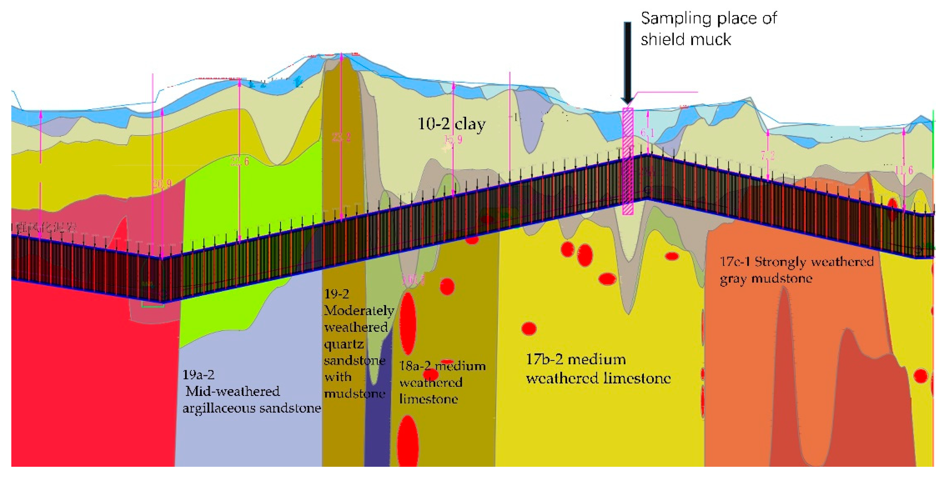
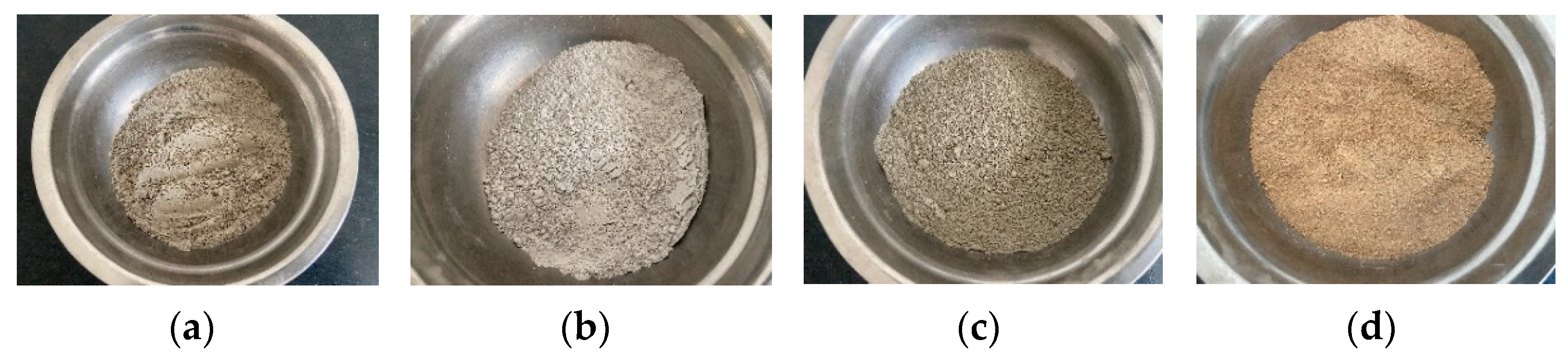
2.1. Materials

The test muck was taken from the fifth-section interval of the second phase of the Wuhan City Rail Transit Line 11 East project, near the proposed stopping point shown in Figure 1. The muck is composed of clay and is grayish–yellow in color, and its basic physical index is shown in Table 1. The gradation curve of shield residues is shown in Figure 2, with a uniformity coefficient Cu > 5 and curvature coefficient 1 < Cc < 3. The gradation is good.
Calcium carbide slag was produced by a limited company in Henan that produces water purification materials. The slag had the appearance of an off-white powder with a certain irritating odor and a specific gravity of 2.03. The fly ash was produced by a power plant in Henan Province, and it had the appearance of gray powder. The content of SiO2 and Al2O3 in the fly ash reaches 79.42%, and the content of CaO and MgO is 6.23%, meaning that it constitutes silica–alumina type fly ash. The cement was produced by Huaxin Cement Co. The shield muck, calcium carbide slag, fly ash, and Portland cement are shown in Figure 3, and their chemical compositions are shown in Table 2.

2.2. Test Protocol

The shield muck has a high water content, a high viscosity, and a flow plastic state. To facilitate the subsequent test, it was necessary to pretreat the undisturbed shield muck.
The shield muck was dried naturally and then crushed by a soil crusher. The crushed shield muck was then passed through a 2 mm standard sieve by a vibrating sorter according to geotechnical test specifications [15]. After sieving, the soil samples were put into an oven at 105 °C, dried to a constant weight, and removed for use. The compaction test was carried out using the heavy compaction method to determine the specimens’ maximum dry density and optimum water content under the dosing of plain soil and each curing agent. The unconfined compressive strength test was based on the maximum dry density and optimum moisture content obtained from the compaction test, and the specimen dosage was calculated by controlling 96% compaction. The sample was pressed into a cylindrical shape of Φ50 mm × 100 mm using the static pressure method. The molded specimens were wrapped in cling film and placed in a standard maintenance box for 7, 14, and 28 days [16]. Three parallel specimens were set for each curing agent dose, and the results were averaged. Based on previous research [17,18,19,20,21,22,23], the dosing amounts of calcium carbide slag and fly ash were designed as shown in Table 3, and the unconfined compression test was carried out according to the dosing amounts presented in Table 3. The specimens were loaded until they were destroyed, and the dosing amounts of calcium carbide slag and fly ash that were optimal for stabilizing the shield slag soil in the selected dosing interval were obtained according to the results of the unconfined compression test. After the strength test, the specimens were taken for XRD and SEM tests to determine their internal composition and microstructure under different doping ratios.
Dry–wet cycle tests were conducted to further investigate the stability and durability of the cured residual soil. The dry–wet cycle test was carried out following the method described in previous research [24]. Three kinds of samples with the lowest, medium, and highest strength were selected to carry out the dry–wet cycle test.

2.3. Methods

According to the test specification [15], the sieved and dried plain soil, as well as the cured soil mixed with different proportions of the curing agent, was subjected to light compaction tests to obtain the optimum moisture content and maximum dry density, and the samples were mixed with different proportions of calcium carbide slag and fly ash.
Carbide slag and fly ash were added to the shield muck according to the predetermined proportions and mixed evenly; water was added until the mixture reached the optimum moisture content; the mixture was thoroughly mixed again; and then it was put into a sealed bag and left for 24 h. When making the specimens, the resting mixture was put into a light compaction steel mold with an inner diameter of 50 mm and a height of 100 mm in 3 layers. After compression molding, the sponges were wrapped with cling film and placed in a standard curing box with a temperature of (20 ± 2) °C and a humidity of 95%. After reaching the maintenance curing age, the specimens were removed. A WDW-10E-microcomputer-controlled electronic universal testing machine was used to carry out the unconfined compression test on the test block. The vertical strain rate was set to 1 mm/min. The value was recorded when the strength of the specimen reached its peak. At this point, the specimen was destroyed internally. The test continued until the specimen surface showed obvious cracks, at which point it was stopped. The average value of three parallel specimens measured in each group of tests was taken as the experimental result for analysis. After the compression test, the specimens were finely crushed internally and processed to a constant weight in the freeze-dryer. The dried, crushed pieces were internally ground into a powder and passed through a 0.075 mm sieve for the XRD test. The XRD scanning speed was 5 (°)/min, and the range was 5~80°. The internal section of the dried specimen block was selected for the SEM test. In the dry–wet cycle test, the specimen was standardized for 28 d and then dried at room temperature (20 ± 3) °C for 24 h. The specimen was numbered, and its mass, diameter, and height measured; then, the specimen was placed in a water bath, which was slowly filled with water until the top surface of the specimen was submerged. The specimens were immersed in a water bath at (20 ± 0.5) °C for 24 h, and their morphology was observed. Then, the specimen was taken out and put on the absorbent paper for 1 h; the moisture on the specimen’s surface was wiped off; the specimen’s mass, diameter, and height were measured; and the specimen’s appearance was recorded. This constitutes a dry–wet cycle. It was repeated five times to complete a five-stage dry–wet cycle. The compressive strength without a lateral limit of the 3 groups of ratios was measured after completing 1, 3, and 5 dry–wet cycles, and 2 parallel specimens were taken from each group.

3. Analysis of Test Results

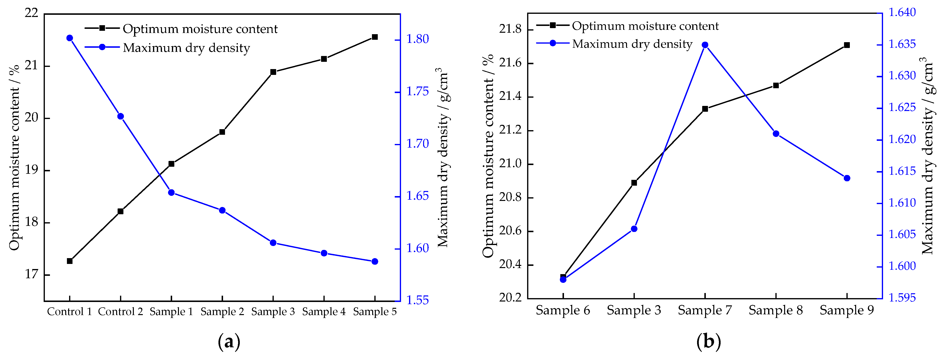
3.1. Compaction Characteristic Analysis

Keeping the proportion of fly ash constant, the trends of optimum moisture content and maximum dry density were investigated for different calcium carbide slag ratios against plain soil (Control Group 1) and mixed with 5% cement (Control Group 2), and the test results are shown in Figure 4.
Figure 4a shows that the optimum moisture content of the treated soil tends to increase, and the maximum dry density tends to decrease with the increase in cement incorporation and calcium carbide slag incorporation. This is because the main component of calcium carbide slag is CaO, which more easily ionizes with the OH− ions in a water hydrolysis reaction to form Ca2+, compared to plain soil without the addition of a curing agent. The reaction consumes a large amount of water, while the products generated by the reaction increase the cementation between soil particles, and a stable agglomerate structure is formed inside the soil, preventing water from continuing to enter the interior. Therefore, the optimum moisture content of the bonding material increases with the increase in the calcium carbide slag admixture. The maximum dry density decreases with increasing curing agent dosing; this is mainly because the specific gravity of cement, calcium carbide slag, and fly ash is smaller than that of shield muck, resulting in the relative density of the mixture being lower than that of the shield residues. The maximum dry density of the specimens showed an overall decreasing trend under the compaction action.
Figure 4b shows that the optimum moisture content of the binding material increases continuously with the increase in the fly ash admixture. The maximum dry density increased first and reached its peak when 18% fly ash was mixed in, and the maximum dry density decreased gradually after the fly ash continued to be mixed in. This phenomenon was mainly due to the small specific surface area of fly ash and the large voids between the particles of calcium carbide slag. For amounts of fly ash lower than 18%, calcium carbide slag and fly ash in the compaction effect mean that the internal particles between the voids fill each other and become more compact, resulting in increasing dry density. When the fly ash admixture exceeds 18%, the amount of calcium carbide slag admixture remains unchanged. Currently, as the compaction effect has been unable to further fill its internal voids, the skeleton between fly ash particles has difficulty achieving further compaction under the compaction effect, resulting in a gradual decrease in its maximum dry density.

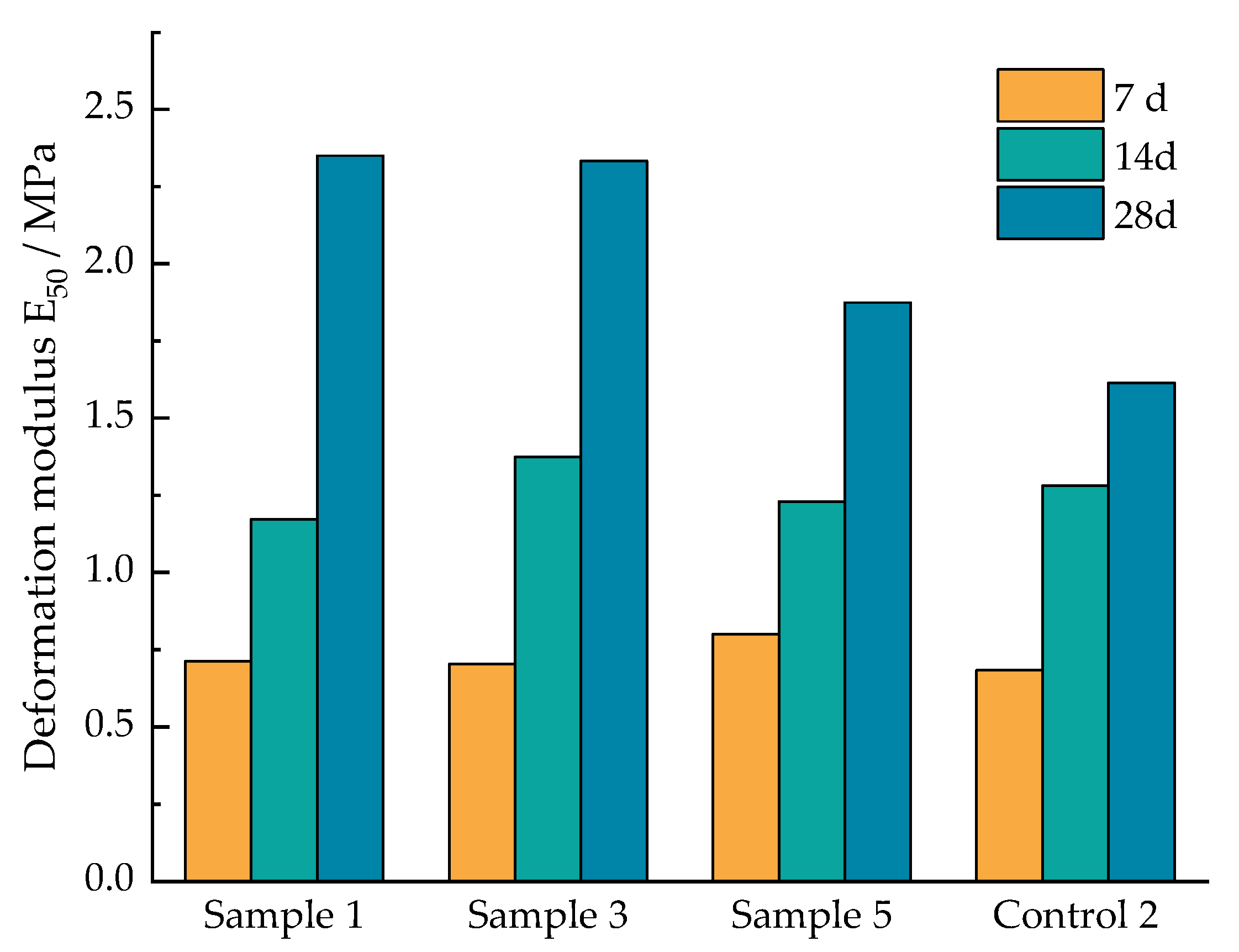
3.2. Analysis of UCS

The effect of calcium carbide slag-fly ash on the strength of cured shield muck is shown in Figure 5. The addition of calcium carbide slag and fly ash can significantly improve the lateral limitless compressive strength of shield muck.
Figure 5a shows that the compressive strength of the specimens increased with the amount of calcium carbide slag and then decreased, and the strength reached its maximum at 10% calcium carbide slag and 15% fly ash (Sample 3). With the best curing effect, the unconfined compressive strength of the shield residue soil (Control Group 1) was 0.275 MPa at 7 days of maintenance. When 6% calcium carbide slag and 15% fly ash (Sample 1) were added, the unconfined compressive strength of the cured soil reached 1.280 MPa, an increase of 365% compared to Control Group 1, representing a significant increase in strength. The compressive strength increased from 1.280 MPa to 1.428 MPa when the dosing of the calcium carbide slag increased from 6% to 10%, reaching its maximum. When the dosing of calcium carbide slag continued to increase from 10% to 14%, the compressive strength of the cured soil gradually decreased to 1.197 MPa when 14% calcium carbide slag was incorporated, which was still an increase of 335% compared to Control Group 1. The unconfined compressive strength of Control Group 2 mixed with 5% ordinary Portland cement for 7 days was 1.710 MPa, and the curing effect was better than that of Sample 3. However, after 28 days of maintenance, the unconfined compressive strength of Sample 3 was 3.942 MPa, which was 1.37 times that of Control Group 2. This indicates that under certain conditions, the calcium carbide slag-fly ash curing of shield slag soil can achieve a better effect than that of cement.
Figure 5b shows that the compressive strength of the specimen increases with the increase in the fly ash admixture and then decreases, and it also reaches its maximum in Sample 3. The compressive strength of the cured soil increases significantly with the increase in curing age. The longer the age of maintenance, the greater the increase in the unconfined compressive strength of the specimens.
Short-term and long-term reactions of carbide slag-fly ash can occur in slag soil. The short-term reactions include dehydration, flocculation, and carbonization, while the long-term reactions are related to the formation of various gel compounds in the soil matrix [24]. The test results show that the greater the dosing of calcium carbide slag, the more significant the dewatering effect. This is due to the ability of the CaO in calcium carbide slag to undergo hydration to produce Ca(OH)2, which provides strength to the mix after carbonization and precipitation. At the same time, Ca(OH)2 can react with the active SiO2 and Al2O3 in fly ash in a volcanic ash reaction to produce gelling substances such as hydrated calcium silicate (C-S-H) and hydrated calcium silicate aluminate (C-A-S-H). These gelling substances enhance the skeleton’s strength and fill the pore; the pores are reduced, resulting in lower porosity, which improves the mix gradation to some extent, resulting in greater inter-particle cohesion and increased mix strength. In addition, the increase in the inter-particle adhesion force causes the volume of flocculent gel agglomerates to become larger, further increasing the strength of the cured soil. The reaction process of volcanic ash is longer, less gelatinous material is generated in the early stage of the reaction, and the flocculent gel agglomeration process is slow. However, with increasing age, the volcanic ash reaction continues, prompting more and more gelatinous material to be generated and the flocculent gel agglomerates to become larger and larger, so the increase in strength after 14 to 28 days of maintenance is more significant than that after 7 to 14 days of maintenance. The early reaction rate of cement is faster than that of carbide slag-fly ash, and the compressive strength of Control Group 2 was the highest at 7 days of maintenance. However, as the reaction of the volcanic ash proceeded, the compressive strength of the test group increased more rapidly; the compressive strength of Sample 3 exceeded that of Control Group 2 at 14 days, and the compressive strength of all test groups exceeded that of Control Group 2 at 28 days.
With increasing amounts of calcium carbide slag, excessive calcium carbide slag particles absorb some of the water, making the hydration reaction process exhibit slow coagulation and inhibiting the volcanic ash reaction. Meanwhile, the excess calcium carbide slag affects the shield muck particle gradation, reducing the friction between the shield muck particles so that the unconfined compressive strength decreases. Figure 5b shows that by increasing the content of fly ash, more active SiO2 and Al2O3 are added to the mixture, and they react in the mixture to form a silicon aluminum geopolymer gel, which improves the compressive strength of the solidified soil. However, the strength is reduced after too much fly ash is added, partly because there are few calcium-rich components in fly ash. The greater the amount of fly ash admixture, the lower the percentage of calcium content in the mixture, and the less C-S-H and C-A-S-H are formed by hydration, which directly affects the strength of the mixture. On the other hand, with the increase in fly ash content, more of the structurally stable sodium aluminosilicate (N-A-S-H) polymer is formed. Although it has good strength, it cannot function the same as bonding and polymerizing soil particles such as C-S-H and C-A-S-H, so too much fly ash is not conducive to improving the mixture’s strength [25]. At the same time, the formation of the monomer in the geopolymer matrix depends entirely on the Si/Al ratio in the raw material. The Si/Al ratio is one of the most important factors affecting geotechnical synthesis. Ratios that are too high or too low significantly limit the formation of the polymer. The incorporation of excessive fly ash affects the Si/Al ratio of the mixture [26].

3.3. Characteristics of the Stress–Strain Curve Relationship

Figure 6a–c show the stress–strain curves of the specimens after 7, 14, and 28 days of maintenance with different doping levels of calcium carbide slag. The figures show that the stress–strain process exists in the pore fracture compacting stage, the elastic deformation to microplastic fracture stable development stage, the progressive rupture stage, and the post-rupture stage [27].
Comparing Figure 6a–c, it can be seen that the growth rate of each stress–strain stage of the specimens with different calcium carbide slag content is about the same at 7 and 14 days of curing, and the growth rate of each stage of the stress–strain of the specimens with different calcium carbide slag content appears significantly different at 28 days of curing. When the cured soil has a low maintenance age, the stress–strain curve reaches peak stress with relatively small, sudden drop changes. However, as the age increases, the peak stress of the cured soil increases, the stress–strain curve rises, and the sudden drop changes obviously; plasticity decreases and brittleness increases. It exhibits typical strain-softening characteristics. Soil structural damage accumulates, and it eventually breaks down.
The ultimate strain is the strain value corresponding to the peak stress on the stress–strain relationship curve, and its magnitude is an important indicator of a material’s toughness and compression deformation [28]. Generally, the ultimate strains of the specimens at 7 days of curing were greater than those at 14 and 28 days of curing. The ultimate strains of soil cured with calcium carbide slag–fly ash were mainly distributed between 1% and 2.2%, which is similar to Tang’s conclusion that the ultimate strains of cement-cured soil were mainly distributed between 1% and 2.5% [29,30,31].
The deformation modulus is the ratio of the compressive stress to the corresponding compressive strain under unconfined conditions, which reflects the ability of the material to resist elastic–plastic deformation. Therefore, E50 (the secant modulus corresponding to 50% of the peak stress, also known as the deformation coefficient) was chosen to characterize the deformation properties of the material.
The variation pattern of the E50 of soil cured under different amounts of the calcium carbide slag admixture and at different maintenance ages is shown in Figure 7. It can be seen that the deformation modulus E50 of the cured soil does not vary significantly with the amount of calcium carbide slag in the range of calcium carbide slag admixture selected for the test. However, the deformation modulus E50 increased significantly as the maintenance age increased. According to Chen [32] and Horpibulsuk [18], this is because the specimen reacted with the highly reactive SiO2 in the fly ash and with Ca2+ in the calcium carbide slag, resulting in a filling effect and the generation of colloidal hydration products such as C-S-H. This reduces the soil pores and makes the soil structure denser and more stable. Thus, the deformation resistance of soil solidified with carbide slag-fly ash solidified soil is improved.

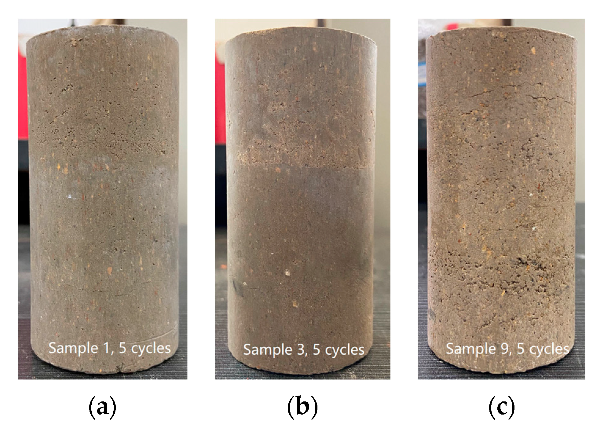
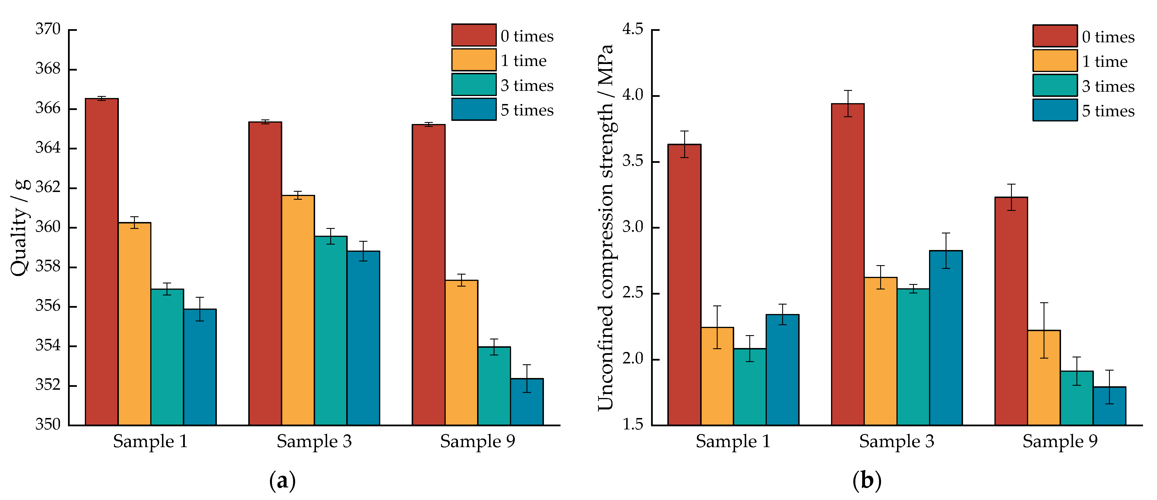
3.4. Effect of the Dry–Wet Cycle on Solidified Shield Muck

The lowest strength (Sample 9), the medium strength (Sample 1), and the highest strength (Sample 3) were selected for the dry–wet cycle test. It was found that the overall structure of the three specimens remained intact after five levels of dry–wet cycles, but there were different degrees of mass loss and damage to the specimens’ surfaces after each level of dry–wet cycles. As shown in Figure 8, the surface of Sample 3 did not show obvious changes at the end of the dry–wet cycle. With the dry–wet cycle, the surface of Sample 1 gradually turned from relatively smooth to rough, producing small holes, and the holes in the specimen at the end of the three cycles were more obvious. The surface of Sample 9 produced a large number of pores and fine cracks at the end of three dry–wet cycles. After each dry–wet cycle, it was obvious that the powder shed from the specimen was suspended and precipitated in distilled water.
The effects of the number of dry–wet cycles on the specimen mass and unconfined compressive strength are shown in Figure 9. Figure 9a shows that the mass and strength of all three specimens decreased with the increase in the number of dry–wet cycles. Specifically, the specimen’s mass decreased the most after the first dry–wet cycle, and, with continued dry–wet cycles, the specimen’s mass loss gradually stabilized. The mass loss rates of Sample 1, Sample 3, and Sample 9 were 2.91%, 1.79%, and 3.52% after the end of 5 dry–wet cycles, respectively. In general, the rate and degree of mass reduction of Sample 3 were much smaller than those of the other specimens, and the rate and degree of mass reduction of Sample 9 were the largest. Figure 9b shows that the unconfined compressive strength of specimens decreased significantly after the first dry–wet cycle, and the continued dry–wet cycles had little effect on the strength of the specimens; the strengths of Sample 1, Sample 3, and Sample 9 after the first dry–wet cycle were 0.62, 0.67, and 0.69 of the strength of the specimens without dry–wet cycles, respectively. After 5 dry–wet cycles, the unconfined compressive strength of Sample 1 decreased from 3.632 MPa to 2.342 MPa; Sample 3’s unconfined compressive strength decreased from 3.942 MPa to 2.826 MPa; and Sample 9’s unconfined compressive strength decreased from 3.232 MPa to 1.793 MPa.
Regarding the reason for these findings, the dry–wet cycle, whereby the sample is repeatedly immersed in water, which is then evaporated, as well as the difference between the water content inside and outside the specimen, lead to the specimen’s surface tensile stress. When the cementation between the specimen particles is insufficient to resist the tensile stress, holes appear on the specimen’s surface. With the increase in the number of cycles, the holes further expand, the soil structure is damaged, and the strength decreases. It is worth noting that the unconfined compressive strength of Sample 1 and Sample 3 after five dry–wet cycles is higher than that after one dry–wet cycle; this is because the water that remains inside the specimen after immersion can promote a hydration reaction during the drying process, increasing the hydration products and improving the internal cementation capacity. The cementation produced between the particles in this process is sufficient to resist the tensile stress caused by the difference in moisture content inside and outside the specimen, and the strength then becomes higher than after the end of the first cycle. The water stability of shield muck cured with calcium carbide slag–fly ash is therefore better.
The stress–strain curves of the three specimens subjected to different numbers of dry–wet cycles are shown in Figure 10. The photos of the damage to the specimens after 28 days and 5 dry–wet cycles are shown in Figure 11.
Figure 10 shows that the ultimate strains of all three specimens were 1–2%. The more dry–wet cycles undergone by Sample 9, the lower its strength. Meanwhile, when maintained for 28 days, Sample 3 showed a rapid decrease in stress in the post-rupture phase; after dry–wet cycles, Sample 3 also showed a slower decrease in stress in the post-rupture phase, and the stress–strain curve after dry–wet cycles showed a strong plastic characteristic, which changed from strain hardening to strain softening. As shown in Figure 11a, the damage sustained by the specimens after 28 days of conditioning was mainly concentrated in the middle, forming through vertical (Sample 3) or oblique (Sample 1 and Sample 9) rupture surfaces. Moreover, after the dry–wet cycles, the damage was mainly situated at the ends of the samples, which were severely broken with a large amount of debris. Although vertical fractures were produced at the rupture surface of Sample 1 after the dry–wet cycles, the fractures did not penetrate the specimen (see Figure 11b), and, from a macroscopic point of view, the strength reduction of the specimen after the dry–wet cycles was mainly caused by the end being crushed first.

4. Microscopic Test Results and Improvement Mechanism

4.1. X-ray Diffraction

Shield muck, calcium carbide slag, fly ash, cement, and representative specimens were selected for XRD analysis. The main components of each group of samples are shown in Figure 12. There is a Ca(OH)2 diffraction peak in the carbide slag; there are SiO2 diffraction peaks in the XRD pattern of fly ash; and aluminum silicate also exists in fly ash. The main minerals in cement are dicalcium silicate and tricalcium silicate. The XRD patterns of the cured soil specimens maintained for 28 days were compared with those of raw materials; a large number of diffraction peaks in the calcium carbide slag disappeared and CaCO3 diffraction peaks appeared. In comparison with the XRD pattern of Control Group 2 and the raw materials, the diffraction peaks of dicalcium silicate and tricalcium silicate in cement disappeared, and CaCO3 and SiS2 diffraction peaks appeared. These substances react within the cured soil [32,33].
The XRD pattern shows that new crystalline phases appeared in Sample 1, Sample 3, and Control Group 2 at 28 days of maintenance, and CaCO3 diffraction peaks appeared at 35.8° and 46.7° in Control Group 2, but these two CaCO3 diffraction peaks disappeared in the soil cured with calcium carbide slag–fly ash. This is due to the reaction of the Ca2+ in the calcium carbide slag with the SiO2 in the fly ash, resulting in a decrease in the CaCO3 content. C-(A)-S-H diffraction peaks were observed at 38.5°, 46.3°, and 50.4° for Sample 3, confirming that these substances react to produce C-(A)-S-H.
The results shown in Section 3.2 indicate that the higher compressive strength of the soil cured for 28 days with calcium carbide slag–fly ash at the optimum admixture is due to the generation of reaction products that can increase the strength of the specimens, such as hydrated calcium silicate, which is consistent with the test results and analysis presented in Section 3.2 and Section 3.3 .

4.2. Scanning Electron Microscope

To further analyze the changes in the microstructure of the cured soil at different maintenance ages and different curing agent doses, the microstructure of the cured soil and the effect of the curing reaction on the pore structure were studied by scanning electron microscopy. The microstructure of the shield muck and Sample 3 at 7, 14, and 28 days with 2000 times magnification is shown in Figure 13.
Figure 13a, shows that the shield muck particles are mostly in face-to-face contact with each other. The mineral matrix is largely flat and continuous, and the flat particles are accumulated locally but are not dense. Many gaps exist between the particles. Sample 3 was maintained for 7 days with little generation of hydration products and uneven distribution. Figure 13e,f show the images of the same position shown in Figure 13a magnified 5000 and 10,000 times, respectively. The aggregation of needle-like and short columnar materials forming a similar net-like structure can be observed, which indicates the occurrence of a hydration reaction. At 14 days of curing, Sample 3 was much denser than at 7 days of curing, showing an obvious reticular structure. Figure 13d shows that many dense reticular C-(A)-S-H gels appear in the interstices of the soil particles and are connected to form a whole reticular gel. However, there are still a small number of pores in the reticular gel that are not completely connected, and the microstructure of the soil cured with calcium carbide slag–fly ash has changed significantly. This finding is consistent with the XRD test results, indicating the presence of C-(A)-S-H in the cured soil specimens.
The internal particles of the soil cured with calcium carbide slag–fly ash are all attached and cemented by the mesh-like C-(A)-S-H gel, and the soil particles are tightly polymerized by this action. The C-(A)-S-H gel, flaky AFm( 3 CaO · Al 2 O 3 · CaSO 2 · 12 H 2 O ), and needle-rod AFt(Ettringite) bind and support the particle interstices, resulting in a significant reduction in the number and size of pores and a substantial increase in the soil’s compactness and strength [34], as shown in Figure 14.
The analysis based on the above microscopic tests shows that the main products ofthe reaction within the cured soil are gelled floccules, needles, and rod and mesh structures, which are favorable to the improvement of the strength of the cured soil samples. This finding is consistent with the strength test results shown in Section 3.2 and Section 3.3.

4.3. Curing Mechanism Analysis

The results of the previous compaction test, strength test, XRD, and SEM tests were integrated, and it was found that the curing mechanism of the shield slag cured with calcium carbide slag–fly ash has three main manifestations: the hydration reaction, volcanic ash reaction, and ion exchange.
  • Hydration reaction: a large amount of the CaO in calcium carbide slag can react with water to generate Ca(OH)2, and the generated Ca(OH)2 can effectively fill the internal pores of the specimen. Meanwhile, dicalcium silicate and tricalcium silicate can react with water to generate C-S-H ( 3 CaO · 2 SiO 2 · 3 H 2 O ) gel [35]. This is the hydration reaction.
    3 CaO · SiO 2 + 3 H 2 O CaO · SiO 2 · H 2 O + 2 Ca ( OH ) 2
    3 CaO · SiO 2 + H 2 O CaO · 2 SiO 2 · 3 H 2 O + Ca ( OH ) 2
    3 CaO · Al 2 O 3 + 6 H 2 O 3 CaO · Al 2 O 3 · 6 H 2 O
    CaO + 2 H 2 O + SO 3 CaSO 4 · 2 H 2 O
    3 CaO · Al 2 O 3 · 6 H 2 O + 3 ( CaSO 4 · 2 H 2 O ) + 6 H 2 O 3 CaO · Al 2 O 3 · 3 CaSO 4 · 32 H 2 O
  • Volcanic ash reaction: The main component of fly ash, SiO2, further reacts with Ca(OH)2, the hydration product of calcium carbide slag, to generate C-S-H ( 3 CaO · 2 SiO 2 · 3 H 2 O ) gel; with the hydrolysis of SiO2, C-A-S-H ( CaO · Al 2 O 3 · 2 SiO 2 · 6 H 2 O ) gel is gradually formed in the late maintenance period, which accelerates the hydration process of the mixture and thus improves the compressive strength of the cured soil.
    SiO 2 + Ca ( OH ) 2 + H 2 O C - S - H ( gel )  
    SiO 2 + Al 2 SiO 5 + Ca ( OH ) 2 + H 2 O C - A - S - H ( gel )
  • Ion exchange reaction: the hydration reaction leads to the precipitation of OH - ions, the OH - concentration increases, and the Si2+ ions in the mixture react with OH - and Ca2+ ions.
Through the above processes, the hydration products in the cured soil develop into a dense three-dimensional mesh structure through agglomeration, precipitation, and flocculation, so that the soil particles are glued to each other and gradually form a dense skeletal structure.

5. Conclusions

In this study, shield muck was cured with calcium carbide slag–fly ash, and the strength change law of the cured slag was investigated by an unconfined compression test, a dry–wet cycle test, X-ray diffraction, and an electron microscope scanning test under different calcium carbide slag and fly ash admixtures and maintenance ages. The curing mechanism was revealed by the microstructure evolution, and the main conclusions obtained are as follows:
(1)
The compressive strength of the cured soil increases with the increase in the dosing of calcium carbide and fly ash, then decreases; it also increases with the increase in the curing age. For the shield slag soil used in this paper, the optimal doses of calcium carbide slag and fly ash are 10% and 15%, respectively, when the strength of the cured soil is the highest. Under certain conditions, shield slag soil cured with calcium carbide slag–fly ash can achieve better results than cement. As the age increases, the peak stress of the specimen increases, the ultimate strain decreases, the stress–strain curve rises with an obvious change in the sudden drop, and the brittleness of the cured soil increases.
(2)
The most significant effect of the first dry–wet cycle on the compressive strength of the specimens, compared with the specimens not subjected to a dry–wet cycle, was that the strength decreased by about a third; the strength of the samples subjected to subsequent dry–wet cycles remained unchanged. The shield slag soil cured with calcium carbide–fly ash exhibited good water stability. The ultimate strains of the 3 specimens that underwent dry–wet cycles were 1%~2%, and the rising and sudden falling trend of the stress–strain curve of the specimens became slower, showing stronger plasticity characteristics and the change from strain hardening to strain softening.
(3)
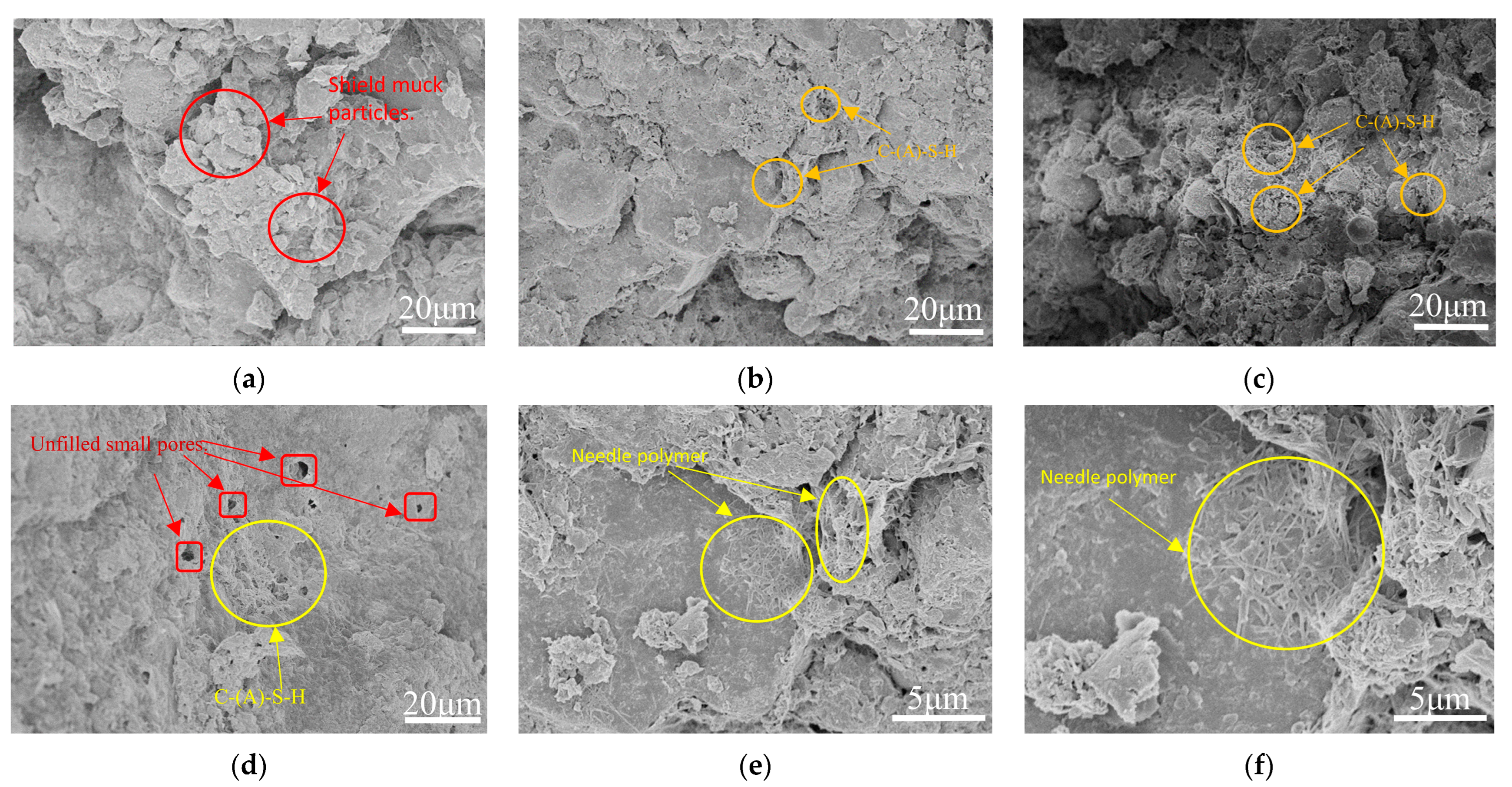
Microscopic tests showed that with increasing age, gels, crystals, and precipitates gradually developed, agglomerated, and were cemented in the soil cured with calcium carbide slag–fly ash. The hydration products were well developed, needle and rod products increased significantly, a dense spatial mesh structure was formed, the soil integrity was improved, and the macroscopic expression showed improved mechanical strength.
(4)
The reaction products mainly comprise hydrated calcium silicate polymeric colloid (C-S-H/C-A-S-H) and calcium alumina (AFt), which together support the inter-soil pores and form a skeletal structure that supports the inter-soil pores.

Author Contributions

Conceptualization, Y.F. and J.W.; methodology, Y.F. and J.W.; validation, Y.F. and J.W.; formal analysis, J.W.; investigation, J.W.; resources, Y.F.; data curation, J.W. and Y.F.; writing—original draft preparation, J.W.; writing—review and editing, Y.F. and X.X.; visualization, J.W. and F.Z.; supervision, Y.F. and F.Z.; project administration, J.W. and Y.F.; funding acquisition, Y.F. and X.X. All authors have read and agreed to the published version of the manuscript.

Funding

The authors are thankful for the financial support from the National Natural Science Foundation of China (No. 52108315), the National Science Foundation of Hubei Province of China (2021CFB286) and Hubei University of Technology Education Development Foundation.

Data Availability Statement

Data sharing is not applicable.

Acknowledgments

We wish to thank the anonymous referees for their careful reading and for providing insightful comments to improve the initial version of this paper. All individuals included in this section have consented to the acknowledgement.

Conflicts of Interest

The authors declare no conflict of interest.

References

  1. Wang, S.Y.; Liu, P.F.; Hu, Q.X.; Huang, S.; Zhong, J.Z.; Liu, Z.R.; Yang, J.S. State-of-the-art on Theories and Technologies of Soil Conditioning for Shield Tunneling. China J. Highw. Transp. 2020, 33, 8–34. [Google Scholar]
  2. Zhu, W.; Qian, Y.J.; Wang, L.; Wei, B.; Lu, K.J.; Fang, Z.K.; Meng, L.F. Classification, Treatment, and Utilization Techniques of Shield Tunnel Abandoned Soil and Related Issues. Tunn. Constr. 2021, 41 (Suppl. S2), 1–13. [Google Scholar]
  3. Xie, Y.P.; Zhang, C.; Yang, J.S.; Fu, J.Y.; Xiao, C.; Zhan, Y.J. Research and Prospect on Technology for Resource Recycling of Shield Tunnel Spoil. Tunn. Constr. 2022, 42, 188–207. [Google Scholar]
  4. Li, W.T.; Ni, P.P.; Yi, Y.L. Comparison of reactive magnesia, quick lime, and ordinary Portland cement for stabilization/solidification of heavy metal-contaminated soils. Sci. Total Environ. 2019, 671, 741–753. [Google Scholar] [CrossRef] [PubMed]
  5. He, L.; Wang, Z.; Gu, W.B. Evolution of freeze-thaw properties of cement-lime solidified contaminated soil. Environ. Technol. Innov. 2021, 21, 101189. [Google Scholar] [CrossRef]
  6. Ahmed, A.; Issa, U.H. Stability of soft clay soil stabilised with recycled gypsum in a wet environment. Soils Found. 2014, 54, 405–416. [Google Scholar] [CrossRef] [Green Version]
  7. Benhelal, E.; Zahedi, G.; Shamsaei, E.; Bahadori, A. Global strategies and potentials to curb CO2 emissions in cement industry. J. Clean. Prod. 2013, 51, 142–161. [Google Scholar] [CrossRef]
  8. Hussain, J.; Khan, A.; Zhou, K. The impact of natural resource depletion on energy use and CO2 emission in Belt & Road Initiative countries: A cross-country analysis. Energy 2020, 199, 117409. [Google Scholar]
  9. Noaman, M.F.; Khan, M.A.; Ali, K.; Hassan, A. A review on the effect of fly ash on the geotechnical properties and stability of soil. Clean. Mater. 2022, 6, 100151. [Google Scholar] [CrossRef]
  10. Zhang, Y.J.; Wang, J.; Zhang, L.L.; Li, C.L.; Jiang, H.; Ba, X.Z.; Hou, D.S. Study on the preparation and properties of high-belite cementitious materials from shield slag and calcium carbide slag. Constr. Build. Mater. 2022, 355, 129082. [Google Scholar] [CrossRef]
  11. Baskar, I.; Keerthana, K.; Sakthisri, K.; Sona, R. Effect of calcium carbide residue and fly ash in soil stabilization for sand mixed clayey soil. Mater. Today Proc. 2022, 69, 1253–1259. [Google Scholar] [CrossRef]
  12. Xu, F.; Jiang, C.Z.; Zhang, S.J.; Yang, D.; Li, S.S. Experimental Study on Alkali Activated Slag Solidification of Earth Pressure Balance Shield Muck. Chin. J. Undergr. Space Eng. 2022, 18, 849–859. [Google Scholar]
  13. Liu, Y.Y.; Chang, C.W.; Namdar, A.; She, Y.X.; Lin, C.H.; Yuan, X.; Yang, Q. Stabilization of expansive soil using cementing material from rice husk ash and calcium carbide residue. Constr. Build. Mater. 2019, 221, 1–11. [Google Scholar] [CrossRef]
  14. Guo, Q.Y.; Li, B.Y.; Ding, J.W.; Chen, J.G.; Sun, S.; Ma, Y.L. Experimental study on the road performance of slurry shield tunnel residue improved by industrial waste residues. J. Civ. Environ. Eng. 2022, 143, 1–11. [Google Scholar]
  15. JTG 3430-2020; Test Methods of Soils for Highway Engineering. Ministry of Transport of China: Beijing, China, 2020.
  16. Cao, W.; Zhao, J.; Jiang, Z.Y.; Li, Y.Z.; Che, C. Reuse of Abandoned Shield Residues Stabilized by a Sustainable Binder: Assessment of Strength, Durability, and Environmental Properties. Buildings 2023, 13, 738. [Google Scholar] [CrossRef]
  17. Ayodele, F.O.; Fajimi, M.S.; Alo, B.A. Stabilization of tropical soil using calcium carbide residue and rice husk ash. Mater. Today Proc. 2022, 60, 216–222. [Google Scholar] [CrossRef]
  18. Horpibulsuk, S.; Phetchuay, C.; Chinkulkijniwat, A.; Cholaphatsorn, A. Strength development in silty clay stabilized with calcium carbide residue and fly ash. Soils Found. 2013, 53, 477–486. [Google Scholar] [CrossRef] [Green Version]
  19. Latifi, N.; Meehan, C.L. Strengthening of Montmorillonite and Kaolinitic Clays with Calcium Carbide Residue: A Sustainable Additive for Soil Stabilization. In Proceedings of the Geotechnical Frontiers 2017, Orlando, FL, USA, 15 December 2017. [Google Scholar]
  20. Ren, Y.W.; Cai, Y.X.; Liu, F.T. Experimental Study on Properties of Calcium Carbide Slag and Fly Ash Stabilized Coal Gangue Base Mixture. Highw. Eng. 2023, 48, 74–78+97. [Google Scholar]
  21. Liang, S.H.; Zeng, W.H. Experimental Study of Nansha Silt Soil Reinforced with Cement and Fly Ash during Wetting-Drying Cycles. Ind. Constr. 2018, 48, 83–86+43. [Google Scholar]
  22. Li, P.L.; Bi, J.Y.; Pei, Y.; Zhu, D.J. Analysis of Performance Improvement of Carbide Slag Stabilized Loess by Adding Fly Ash. Highw. Eng. 2022, 47, 146–152. [Google Scholar]
  23. Cheng, Z.; Cui, G.H.; Gao, Y.H.; Gang, H.H.; Gao, Z.L.; Yang, Z.; Zhang, X. Mechanical Properties of Fly Ash Reinforced Subgrade Soil in Seasonally Frozen Area. Bull. Chin. Ceram. Soc. 2021, 40, 3854–3864,3875. [Google Scholar]
  24. He, J.; Shi, X.K.; Li, Z.X.; Zhang, L.; Feng, X.Y.; Zhou, L.R. Strength properties of dredged soil at high water content treated with soda residue, carbide slag, and ground granulated blast furnace slag. Constr. Build. Mater. 2020, 242, 118126. [Google Scholar] [CrossRef]
  25. Palomo, A.; Grutzeck, M.W.; Blanco, M.T. Alkali-activated fly ashes: A cement for the future. Cem. Concr. Res. 1999, 29, 1323–1329. [Google Scholar] [CrossRef]
  26. Zhang, J.J.; Li, B.; Yu, C.; Zhang, M.Y. Mechanical properties of slag-fly ash based geopolymer stabilized sandy soil. Rock Soil Mech. 2022, 43, 2421–2430. [Google Scholar]
  27. Zhao, H.; Xie, Y.J.; Long, G.C.; Li, N.; Zhang, J.W.; Cheng, Z.Q. Mechanical Characteristics and Stress and Strain Analysis of Concrete with Bonding Interface Under Impact Load. J. Shanghai Jiaotong Univ. 2022, 56, 1208–1217. [Google Scholar]
  28. Li, L.H.; Han, Q.P.; Yang, X.; Xiao, H.L.; Li, W.T.; Huang, S.P. Mechanical properties and micro-mechanisms of RHA-cement solidified sludge. China Civ. Eng. J. 2022. [Google Scholar] [CrossRef]
  29. Li, L.H.; Zhang, H.Q.; Xiao, H.L.; Pei, Y.Y.; Wang, J.Z. Mechanical and microscopic properties of alkali-activated fly-ash-stabilised construction and demolition waste. Eur. J. Environ. Civ. Eng. 2020, 27, 2661–2677. [Google Scholar] [CrossRef]
  30. Liang, R.W.; Zhang, M.; Bai, X.H. Analysis of laboratory test results of cemented soil. Rock Soil Mech. 2001, 22, 211–213. [Google Scholar]
  31. Kun, D.; Bian, X.Y.; Chen, J.L.; Bai, J.L. Experimental investigation on clay stabilized by cement and waste brick fine aggregate. Chin. J. Geotech. Eng. 2021, 43 (Suppl. S2), 174–177. [Google Scholar]
  32. Chen, I.A.; Juenger, M.C.G. Incorporation of coal combustion residuals into calcium sulfoaluminate-belite cement clinkers. Cem. Concr. Compos. 2012, 34, 893–902. [Google Scholar] [CrossRef]
  33. Bhagath Singh, G.V.P.; Subramaniam, K.V.L. Quantitative XRD study of amorphous phase in alkali activated low calcium siliceous fly ash. Constr. Build. Mater. 2016, 124, 139–147. [Google Scholar] [CrossRef]
  34. Wei, G.Q.; Dong, B.Q.; Fang, G.H.; Wang, Y.S. Understanding reactive amorphous phases of fly ash through the acidolysis. Cem. Concr. Compos. 2023, 140, 105102. [Google Scholar] [CrossRef]
  35. Su, Y.H.; Luo, B.; Luo, Z.D.; Xu, F.; Huang, H.; Long, Z.W.; Shen, C.P. Mechanical characteristics and solidification mechanism of slag/fly ash-based geopolymer and cement solidified organic clay: A comparative study. J. Build. Eng. 2023, 71, 106459. [Google Scholar] [CrossRef]
Figure 1. Longitudinal section view of shield muck taking material.
Buildings 13 01707 g001
Figure 2. Shield muck grading curve.
Buildings 13 01707 g002
Figure 3. Test material: (a) Fly ash; (b) Calcium carbide slag; (c) Portland cement; (d) Shield muck.
Buildings 13 01707 g003
Figure 4. The trend of compaction test of specimens with different proportions: (a) Trend of compaction tests with different calcium carbide slag ratios; (b) Trend of compaction tests with different fly ash ratios.
Buildings 13 01707 g004
Figure 5. Unlimited compressive strength under different dosages: (a) Different calcium carbide slag content; (b) Different fly ash content.
Buildings 13 01707 g005
Figure 6. Stress-strain curves under different calcium carbide slag dosages: (a) 7 d; (b) 14 d; (c) 28 d.
Buildings 13 01707 g006
Figure 7. The change of deformation modulus E50 of specimen.
Buildings 13 01707 g007
Figure 8. After the dry–wet cycle, the sample surface: (a) Sample 1, 5 cycles; (b) Sample 3, 5 cycles; (c) Sample 9, 5 cycles.
Buildings 13 01707 g008
Figure 9. Quality and unconfined compressive strength vary with the number of dry–wet cycles, (a) Quality; (b) Unconfined compressive strength.
Buildings 13 01707 g009
Figure 10. Stress-strain curve of the specimen under different dry–wet cycle times: (a) Sample 1; (b)Sample 3; (c) Sample 9.
Buildings 13 01707 g010
Figure 11. Photograph after specimen failure: (a) After 28 days of maintenance; (b) After dry–wet cycle.
Buildings 13 01707 g011
Figure 12. XRD diffraction comparison.
Buildings 13 01707 g012
Figure 13. Microstructure of shield muck and sample 3: (a) Shield muck; (b) Sample 3, 7 days; (c) Sample 3, 14 days; (d) Sample 3, 28 days; (e) Sample 3, 7 days, 5000 times; (f) Sample 3, 7 days, 10,000 times.
Buildings 13 01707 g013
Figure 14. Internal cementation of pores: (a) Sample 3, 2000 times; (b) Sample 3, 5000 times; (c) Sample 3, 10,000 times; (d) AFt and AFm, 40,000 times.
Buildings 13 01707 g014
Table 1. Basic physical properties of shield muck.
Properties of Shield MuckShield Muck Sample
Initial Water Content (ω/%)42.3
Liquid   Limit   ( ω L /%)43.7
Plastic   Limit   ( ω P /%)23.5
Plasticity   Index   ( I P )20.2
Liquidity   Index   ( I L )0.931
Specific   Density   ( Ρ )2.54
Maximum Dry Density (g/cm3)1.802
Optimum Moisture Content (%)17.27
Coefficient of Curvature, Cc2.48
Coefficient of Uniformity, Cu59
Table 2. Chemical composition of calcium carbide slag, fly ash, and cement (%).
Sample NameCaOSiO2Al2O3MgOFe2O3TiO2SO3Na2O
Calcium Carbide Slag86.252.211.930.421.070.102.750.05
Fly Ash5.3854.8424.580.855.85
Portland Cement62.3421.175.482.763.85
Table 3. Tests on unconfined compressive strength.
SampleDosageCuring Age (Day)
Control Group 10%CS + 0%FA + 0% cement7 days
14 days
28 days
Control Group 20%CS + 0%FA + 5% cement
Sample 16%CS + 15%FA
Sample 28%CS + 15%FA
Sample 310%CS + 15%FA
Sample 412%CS + 15%FA
Sample 514%CS + 15%FA
Sample 610%CS + 12%FA
Sample 710%CS + 18%FA
Sample 810%CS + 21%FA
Sample 910%CS + 24%FA
Note: CS is calcium carbide slag and FA is fly ash in the doping amount; control group 1 is plain soil, and control group 2 is mixed with 5% cement. Curing agent admixture is the ratio of curing agent to dry soil mass.
Disclaimer/Publisher’s Note: The statements, opinions and data contained in all publications are solely those of the individual author(s) and contributor(s) and not of MDPI and/or the editor(s). MDPI and/or the editor(s) disclaim responsibility for any injury to people or property resulting from any ideas, methods, instructions or products referred to in the content.

