Article

Static Experimental Study on New Arc Multi-Tendon CFRP Cable Anchorage System

1
Department of Bridge Engineering, Tongji University, Shanghai 200092, China
2
Shanghai Municipal Engineering Design Institute (Group) Co. Ltd., Shanghai 200092, China
*
Author to whom correspondence should be addressed.
Buildings 2023, 13(3), 669; https://doi.org/10.3390/buildings13030669
Submission received: 18 January 2023 / Revised: 17 February 2023 / Accepted: 27 February 2023 / Published: 2 March 2023
(This article belongs to the Special Issue New Trends in Seismic Performance Evaluation)

Abstract

:
CFRP has the potential to replace steel cables in large-span cable-stayed bridges due to its high strength and lightweight material properties. However, the weak lateral force performance of CFRP material creates the challenge of anchoring. This study introduces a new inner cone + arc + straight cylinder bond-type anchorage system to optimize CFRP tendons’ force state. Experimental and finite element analyses verified the new anchoring system’s performance. In static load tensile tests, six groups of seven CFRP tendon anchorage systems with different sleeve grooves were used to study the failure mode and load–strain variation law. The difference in mechanical properties between the new and traditional anchorage is evaluated in the finite element analysis. The results indicate that the new anchorage system can lower the stress concentration in the anchorage zone and enhance anchorage performance. The groove design of the sleeve can effectively increase the anchoring efficiency, where the groove depth is proportional to the anchoring efficiency and the groove spacing is inversely proportional to the anchoring efficiency. The magnitude of the stress inhomogeneity in the multi-tendon anchoring system during tensioning is proportional to the beginning conditions and the load size. When the inner wall of the sleeve becomes more abrasive, the force heterogeneity of the anchorage system reduces. The tests and finite element analysis show that the new anchoring may improve stress distribution and anchorage efficiency. In engineering practice, it can be utilized as a dependable anchorage system.

1. Introduction

Structural issues are becoming increasingly evident with the increase in bridge spans, such as suspension bridges and cable-stayed bridges, and their use in cross-sea engineering. As the span rises, the steel cable’s cross-sectional area increases nonlinearly, resulting in an increase in the ratio of self-weight stress to allowed stress, which restricts bearing efficiency [1,2]. In contrast, most long-span bridges are transoceanic structures. This makes the steel cables susceptible to fatigue and corrosion damage, lowering the structure’s durability. Studies have shown that replacing typical steel cables with a new lightweight, high-strength, and durable material can increase the bearing capacity and service life of a bridge [3]. Carbon-fiber-reinforced polymer (CFRP) has high specific strength and stiffness, does not corrode, and has exceptional fatigue performance [4]. In terms of dynamic performance, the CFRP cable processes significantly higher natural frequencies than steel cable, which may reduce the likelihood of resonance [5]. Moreover, employing CFRP improves the nonlinear dynamic performance of the cable [6]. The above characteristics show that CFRP can solve the structural problems encountered in long-span bridges. Thus, it can be chosen as an ideal material to replace traditional steel cable.
Although CFRP has great longitudinal qualities, it still has certain practical obstacles, such as being difficult to anchor, low fire resistance, and high unit price [7]. The fire resistance can be enhanced by spraying the fire-resistant coating on the surface of CFRP or changing the material matrix. Despite the higher initial cost, the long-span CFRP bridge can still achieve a lower life-cycle cost than the steel bridge [8]. The most challenging problem to solve is the anchoring problem. CFRP is an anisotropic material that has low strength and elastic modulus in the vertical fiber direction. CFRP’s shear strength, interlaminar tensile strength, and interlaminar shear strength are only 5% to 20% of the tensile strength and are prone to failure under lateral forces [7]. Based on the above defects, the anchor zone of CFRP cables has become a weak point of the system. The traditional steel cable anchorage will produce a vast lateral clamping force at the anchorage end, leading to the early failure of CFRP cables in the anchorage zone. Therefore, it is necessary to develop a new anchorage system in combination with CFRP’s material characteristics.
Existing CFRP anchoring systems can be divided into three categories based on their anchoring mechanisms: bond-type anchorage, mechanical gripping anchorage, and composite anchorage [9]. Many researchers have developed new forms of anchorage. Cai et al. improved the clip anchor for CFRP tendons by using aluminum sheets, significantly reducing anchor slippage and improving anchoring efficiency [10]. The mechanical behavior analysis theories and load-carrying capacity evaluation model of wedge-type anchors were presented by Zhuge et al. In addition, a method for designing optimal anchorage systems was developed based on their findings [11]. Hossein et al. presented comparative research on wedge-barrel anchor system geometrical optimization. Their study utilized the Tsai-Wu failure criterion to evaluate the stress concentration, which can be lowered by the anchor with a curved profile [12]. Ai et al. designed a novel self-anchored CFRP anchorage system that differs from the previously mentioned three types of anchorage. The anchorage design parameters were subjected to numerical simulation and experimental testing [13]. In engineering practice, bond-type anchorage is more prevalent, resulting in several research achievements on anchorage mechanisms and optimization. Feng et al. [14] established a theoretical model for the elastic shear stress distribution at the CFRP–adhesive interface of bond-type anchors and validated it in the preliminary anchorage design. Wang et al. investigated how diameter affects the longitudinal tensile and anchoring properties of CFRP rods. The conclusion demonstrates that larger-diameter rods require a longer anchoring length. When a large cross-sectional area is required, a multiple CFRP cable anchorage system should be used [15].
The current research results reveal that increasing the diameter of a single cable does not improve bearing capacity. A multi-tendon anchorage method should be used for CFRP anchorage in practical engineering. However, the stress situation of a multi-tendon anchorage system is more complex than that of a single-tendon anchorage system. Correlational studies are increasingly being conducted on this subject by researchers. Zhuge et al. designed an innovative 19-tendon anchorage system. The static and fatigue properties of the anchor were studied experimentally, and an optimum anchorage design was presented [16]. Zhu et al. derived a theoretical analysis of sufficient conditions for anti-slip failure and necessary conditions for the safety of CFRP. In addition, four specifications (12, 19, 37, and 121 tendons) and static testing were conducted for verification investigations [17]. Feng et al. developed a CFRP anchorage system with 37 tendons. It was subjected to static tensile and fatigue tests. The test findings suggest that each layer’s cable is synchronous, but the force distribution between the layers has yet to be determined [18]. Zhou et al. conducted multiple groups of 37 tendon anchors and developed a multi-tendon finite element model. Based on their research findings, they discussed failure mechanisms and stress inhomogeneity. It was also suggested that the anchorage system be optimized by spreading cables or modifying the stiffness of the load transmission component [19,20,21]. Kim et al. developed a three-tendon and seven-tendon anchorage system using several variables, the validity of which was confirmed by experiments [22].
Based on the existing experimental research and finite element analysis results of the multi-tendon CFRP anchorage system, the anchorage can be further optimized. The existing inner cone + straight anchorage has a large stress concentration at the junction point, which needs to be solved. Solving the problem of overall sliding out of the adhesive through the second interface roughness treatment is also necessary. Simultaneously, the unevenness of the force impacting the load-carrying capability of the multi-tendon anchorage system should be considered. This study presents a new type of inner cone + arc + straight cylinder bond-type anchorage. The difference between it and the traditional anchorage was compared by finite element analysis. The influence of the roughness of the second interface (epoxy resin–sleeve) on the anchoring efficiency, failure mechanism, and stress distribution was then evaluated using the static load tensile test by varying the sleeve’s groove depth and groove spacing. Finally, the novel anchorage system’s stress inhomogeneity was explored by developing the idea of the inhomogeneity coefficient. This work proposes a reliable performance anchorage system, and the anchorage optimization concept can be used to develop other anchorages, thereby promoting CFRP engineering practice.

2. Materials and Methods

2.1. Preparation of Specimen

In the static load test, an embossed CFRP tendon was utilized due to its uneven surface, which can generate greater friction and mechanical biting force with the bonding medium. NanJing Nuertai Composite Material and Equipment Manufacturing Co., Ltd. produced the CFRP tendons used in this investigation. The extrusion technique of external pulling and forming under extrusion molding generated CFRP tendons with correct dimensions and steady quality, allowing the pulling strength in the fiber direction to be used entirely. Carbon fiber based on PAN is used as the raw material. The mechanical parameters of the CFRP tendon provided by the manufacturer are typical values determined by tensile testing of single CFRP tendons, as indicated in Table 1. The epoxy resin adhesive is the Hilti RE500 tendon planting adhesive whose hardness and mechanical properties are similar to those of the CFRP tendon and resin matrix in the CFRP tendon, respectively. The average bond strength of epoxy resin adhesive is 20.9 MPa, and the average compressive strength is 106.6 MPa. The sleeve material is No.45 steel, and the material property parameters are shown in Table 1.
The anchorage system used in this research is a new inner cone + arc + straight cylinder bond-type anchorage. The new anchorage comprises a sleeve, limit nut, end cover, and buckle, as shown in Figure 1. The end cover has corresponding positioning holes to make CFRP cables pass through and keep parallel. As shown in Figure 2a, the end cover is fastened to the sleeve by six bolts with rings at the ends to allow for movement during assembly. The limit nut is used to secure the specimen to the loading table, making jacking and loading easier. The innovation of the new anchorage is to connect the inner cone section and the straight cylinder with an arc section, of which the radius of the curvature is 3500 mm. Instead of bending the corners, curved tapering can be used to eliminate stress peaks in the inner cone–straight transition section, as shown in Figure 1b. Meanwhile, grooves were excavated at the epoxy resin–sleeve interface to increase the roughness and improve the anchoring efficiency. The angle of the inner cone section of the anchorage is 4°, and the length of the straight section accounts for 1/3. CFRP cables have a centrally symmetrical, 3 mm wide hexagonal distribution. In this test, epoxy resin was infiltrated horizontally. As the perfusion inlet, three holes were machined on the lateral side of the sleeve. Figure 2 depicts the 3D perspective view of the anchorage.
Twelve anchorage systems were utilized in the static load tensile test, separated into six groups. Each set includes 2 steel sleeves, 7 CFRP cables, epoxy resin adhesives, and additional components such as a strain gauge and positioning board. Related parameters are shown in Table 2. The specimens are numbered D-S. D represents the depth of the groove. S represents the spacing of the groove. D0S0 indicates that no treatment is given to the sleeve. The groove angle is 120°, and the breadth is determined by the depth and spacing. As shown in the Figure 3, the width is equal to Δ s + Δ l ( Δ l = 2 3 Δ h). The CFRP cable used in the test is 4.3 m long and has a diameter of 5 mm.

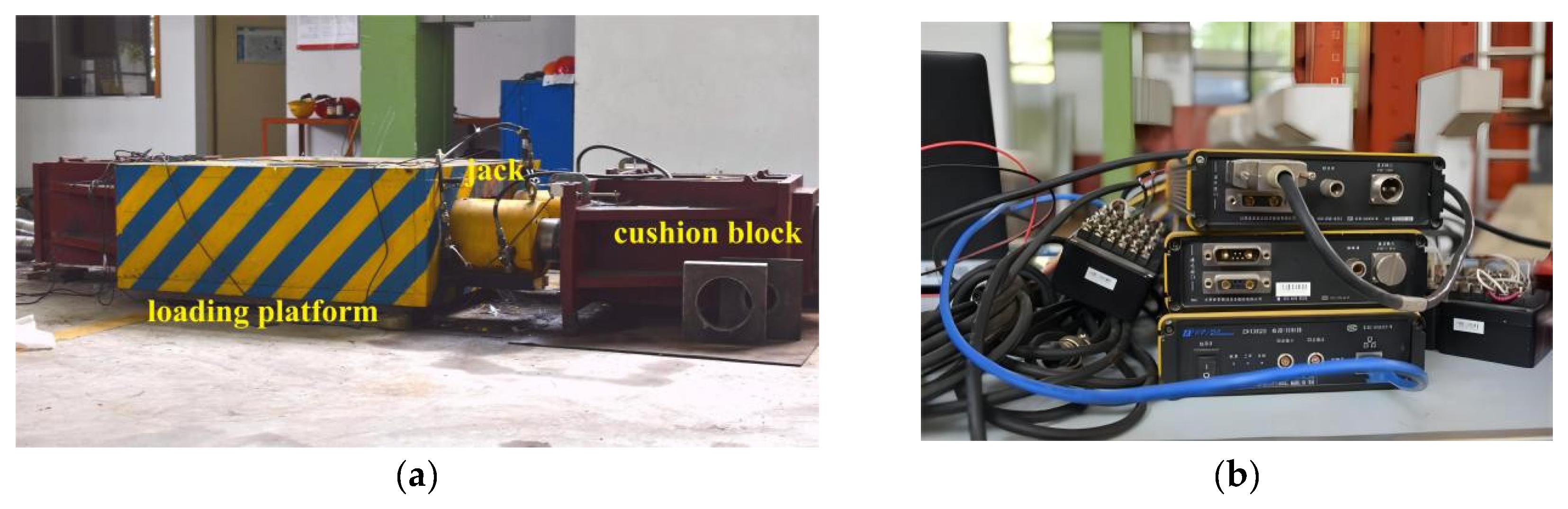
2.2. Test Content and Loading Scheme

The test contents mainly include the following:
  • The ultimate load of the anchorage system;
  • The strain of CFRP cables in the anchorage zone and free section;
  • Failure mode and location of the anchoring system.
Figure 4 depicts the measurement point arrangement of the anchorage system. There are seven longitudinally placed test points and three transversely arranged test points. The strain gauges were numbered X-Y. The location of the longitudinal strain gauge is represented by X, which ranges from 1 to 7, as shown in the Figure 4a. Y represents the transverse strain gauge position, which ranges from 1 to 3.
The tensile test loading equipment is secured at one end and loaded at the other with two jacks. The test used a hydraulic oil pump with a rated pressure of 50 MPa and a DH3820 quasi-static strain test acquisition device, as indicated in Figure 5. This test used a uniform loading scheme with a loading rate of 0.3~0.8 KN/s. Loading will cease when the load cannot be raised due to the failure of the specimen or when the jack has reached its maximum stroke.

2.3. FE Model and Parameters

Using ANSYS version 18.2 mechanical software, an FE model was developed to simulate the effect of anchorage design on anchoring efficiency and stress distribution. SOLID45 elements simulated the sleeve and epoxy resin glue, while SOLID64 elements simulated the CFRP cables. Table 1 displays the specific material properties. The first interface contact behavior is set to BONDED. CONTA174l elements were selected to simulate the inner surface of the medium, and TARGE170 elements were selected to simulate the outer surface of the CFRP cables. The second interface contact behavior is set to STANDARD. CONTA173 elements were selected to simulate the outer surface of the medium, and TARGE170 elements were selected to simulate the inner surface of the sleeve. To ensure that the calculation result converged, the normal contact stiffness factor (FKN) was set to 1.0 and the intrusion tolerance coefficient (FTOLN) to 0.1. In this investigation, the extended Lagrangian algorithm was applied. A 1/4 symmetrical model was employed to simplify the model, as illustrated in Figure 6. The FE model was utilized to examine the contact stress and friction at the first and second interfaces, which were difficult to quantify in the tensile test.

3. Results and Discussions

3.1. Failure Modes and Anchoring Efficiency

Figure 7 depicts the typical failure mechanisms of each specimen of the novel anchorage system during the static load tensile test. As the stress increases, slight aberrant sounds of strand ruptures can be heard during the loading process. The anchoring was ejected from the loading gear with a loud noise when the entire anchorage system failed. The failure modes include interface slip failure, strand brittle fracture failure, and local strand stripping failure. As seen in Figure 7a,c,e, the initial marking points of the cable at the end of the anchorage zone drifted outward. Near the anchorage zone, the surface of the cables is covered in white epoxy residue, indicating that an interface slip failure has occurred. Figure 7b depicts the failure of all cables due to brittle fractures at the end of the anchorage zone. Figure 7d,f show both brittle fracture failure and local strand stripping failure concurrently. Figure 7g reveals that the CFRP fiber of the free part was dispersed in the loading pedestal, while the whole cables were broken into many pieces. After the test’s completion, the anchorage’s end cover was opened, as shown in Figure 7h, which proved that the centering of CFRP cables and the compactness of epoxy resin were good. On the surface of the epoxy resin, white fissures are visible due to external load and restrictions from the steel sleeve and end cover.
η = F c p u F p m = F c p u η p n f p m
The anchoring efficiency coefficient reflects the anchorage performance of the CFRP anchorage system, which is calculated as Equation (1). F c p u represents the failure load of CFRP cables in the tensile test and η p ; represents the efficiency coefficient of CFRP cables, which is related to the number of cables n . When n equals 7, η p equals 0.99; f p m represents the theoretical ultimate tensile strength, calculated by the material parameters shown in Table 1 and Table 2. The results of the specimens are shown in the Table 3.

3.2. Load and Strain Relationship of Cable

The strain gauge at the free section’s midpoint recorded the CFRP cables’ load–strain process. The curves are shown in Figure 8. The corresponding curves of each cable are linear, which is consistent with the linear elastic characteristics of CFRP materials. The curves’ shapes are consistent before the load reaches 20% F c p u , indicating that the stress of each cable can maintain good consistency under low load circumstances. The line shapes gradually separate with the load increase, showing an apparent non-uniformity of stress.
Since the anchorage systems were mainly subjected to axial force, the force of each cable should be close to the same. However, the test results in Figure 8 reflect that the stress between cables is uneven. Three reasons may explain why the uneven forces occurred. Firstly, the length of the free section of CFRP cables is inconsistent due to installation error, which impacts the strain gauge data at the free section’s midpoint. Secondly, as the load increases, the cable and the epoxy resin deformation are not coordinated, resulting in inconsistent readings from the strain gauge, as Bo Feng [13] has noted. Thirdly, due to gravity and colloid extrusion, the cable within the anchoring deviated from the center line during tensioning, resulting in abnormal stress.

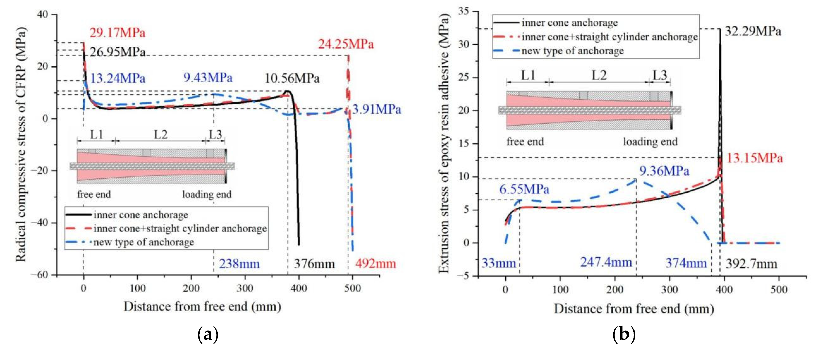
3.3. Mechanical Performance Comparison of Anchorage

The geometric parameters of three anchorages are shown in Table 4. The new anchorage and the inner cone + straight cylinder anchorage have the same total length of 500 mm. The inner cone anchorage has a total length of 400 mm.
The mechanical performance comparison between the new anchorage and two traditional anchorages was conducted under 2200 MPa through the finite element method. Figure 9a shows that the peak radial compressive stress of the conventional anchorage appears at the loading end. In contrast, the peak radial compressive stress of the new anchorage appears in the anchorage area, with a value of 89.2% of the inner cone anchorage’s peak and 38.8% of the inner cone + straight cylinder anchorage’s peak. Figure 9b illustrates the epoxy–sleeve extrusion stress; the peak value of the new anchor is only 28.98% of that of the inner cone anchor. Figure 9c demonstrates that the axial tensile stresses in the CFRP cables of all three anchoring systems increase from the free end to the loaded end and that the peak stresses at the loaded end are almost identical. Figure 9d depicts the cable’s axial displacement. The axial displacement of the new anchor cable at the loading end is only 75.9% of the inner cone anchorage cable and 87.2% of the inner cone + straight cylinder anchorage cable.
When the three types of anchorages are compared, it is clear that conventional anchorages have more evident stress concentration and significant cable displacement. In contrast, because of the circular transition section, the radial compressive stress is more evenly distributed along the length of the new anchorage. Additionally, the radial stress peak of the new anchoring system has been shifted from the loading end to the middle of the anchorage, successfully avoiding the stress concentration induced by the axial stress peak at the loading end and preventing the early failure of the CFRP cable. In terms of slip resistance, the new anchorages’ CFRP cables exhibit less deformation than their conventional counterparts.

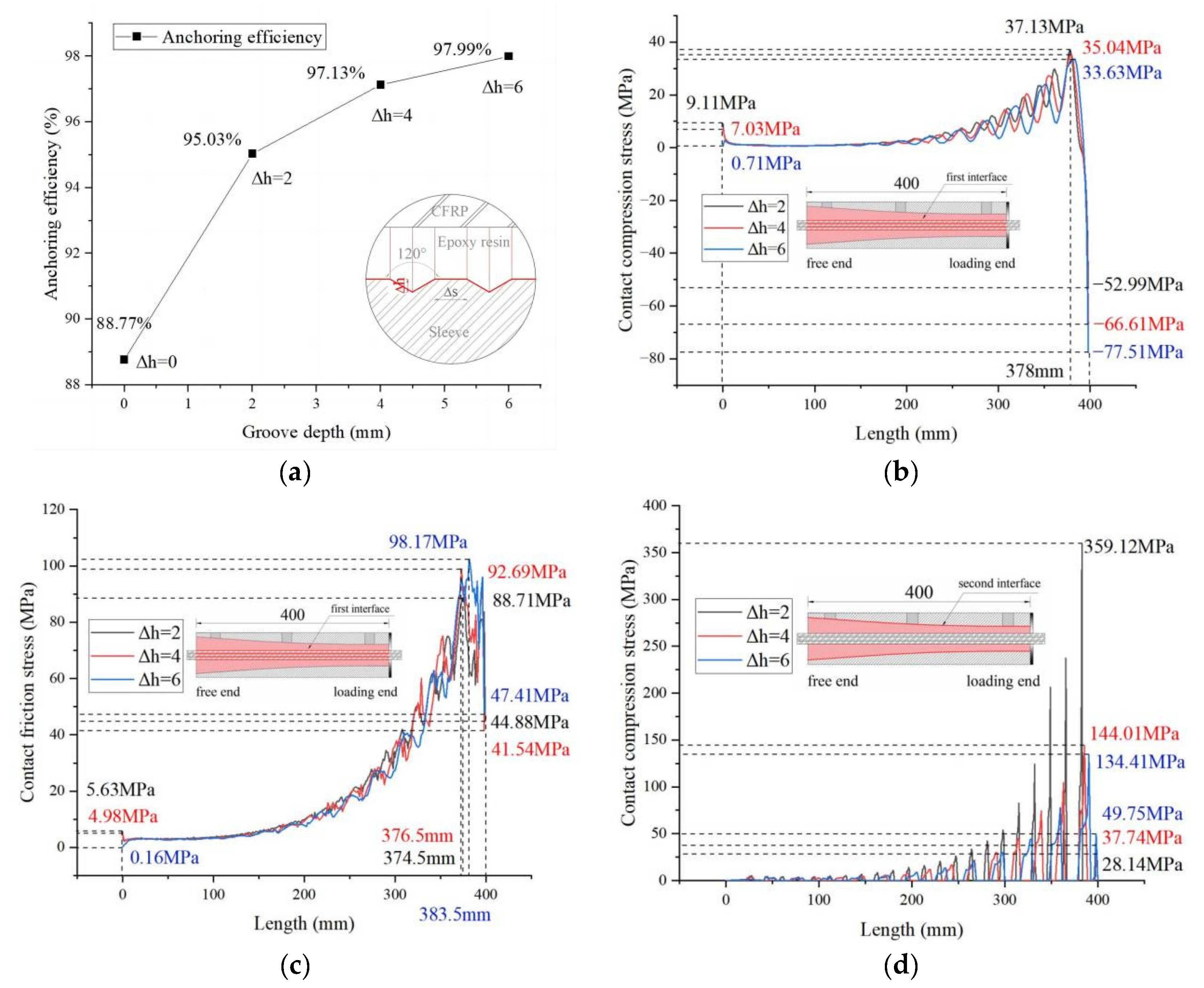
3.4. Effect of Groove Depth

The groove depth Δ h is taken as a variable, with values of 2 mm, 4 mm, and 6 mm, respectively. The anchoring efficiency η of specimens with different groove depths in the tensile tests is shown in Figure 10a. When the inner wall of the sleeve was not treated, the anchoring efficiency was 88.8%, and it increased by 7.05% when the dent depth was 2 mm. When the dent was deepened to 4 mm, the anchoring efficiency rose by 9.42%. When the dent was deepened to 6 mm, the anchoring efficiency rose by 10.39%. The results of finite element analysis are shown in Figure 10b–d. As a result of the tension-induced slippage of the force transfer medium, a groove will contain both a tensile and a compressive surface; hence, the interface contact compressive stress and friction stress will assume the form of a string wave. The crest is on the compressive surface, whereas the trough is on the tensile surface. All curves’ wave peaks increase continuously from the free end to the loaded end.
The experimental results demonstrate that deepening the groove depth increases the efficiency of the new anchorage system by 9.25%, and the rise is not apparent beyond 6 mm if the depth is extended further. According to the finite element results, the contact surface stress is inversely associated with the recess depth, while the second interface contact stress is more obviously affected by the recess depth. Figure 10d shows that the more profound the dent, the lower the contact stress and the higher the anchoring efficiency. This indicates that the radial force controls the anchoring efficiency of the CFRP anchoring system, and the deeper dent depth effectively reduces the radial compressive stress at the second interface, resulting in higher anchoring efficiency.

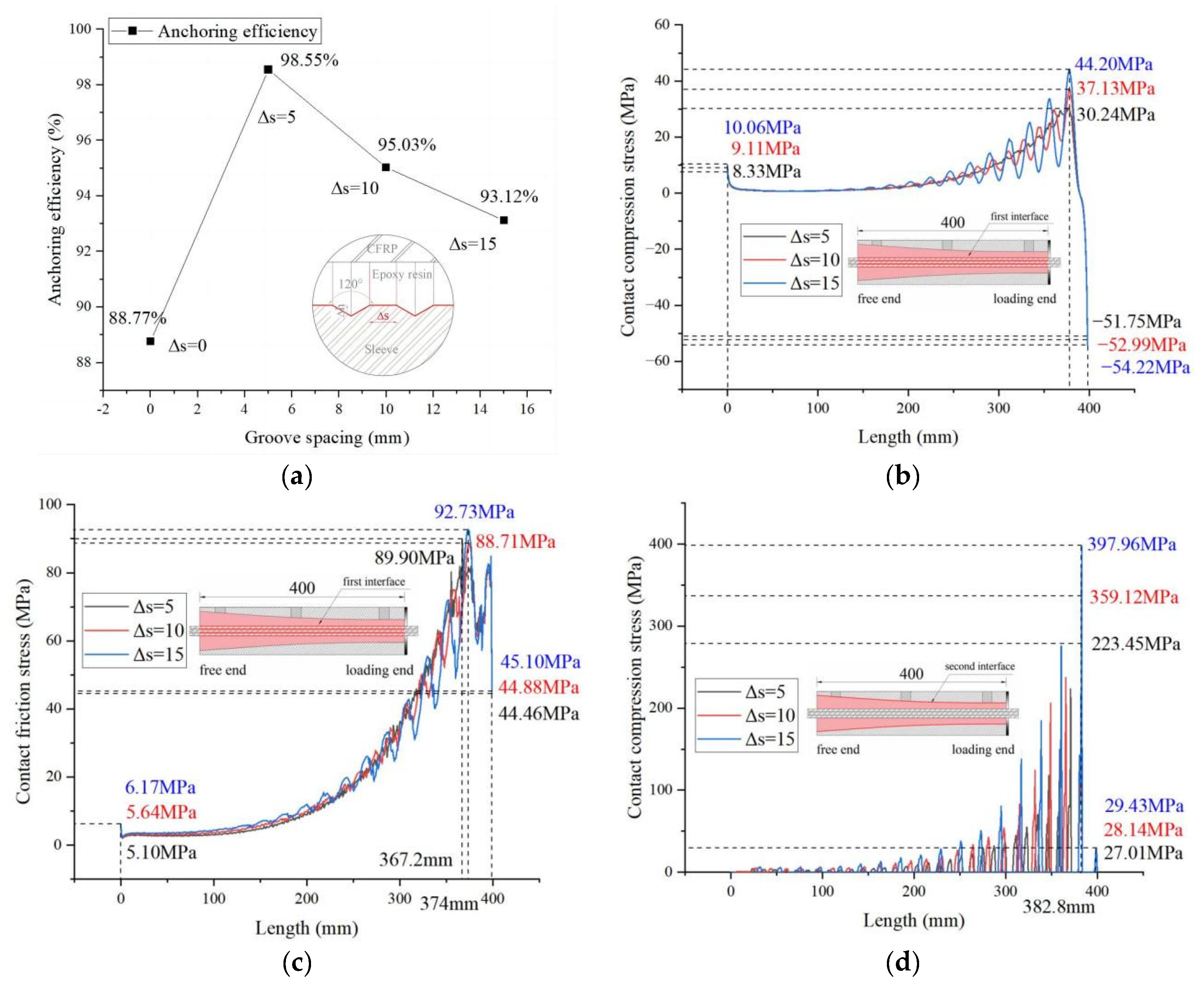
3.5. Effect of Groove Spacing

The groove spacing Δ s is taken as a variable, with values of 5 mm, 10 mm, and 15 mm, respectively. The anchoring efficiency η of specimens with different groove spacing in the tensile tests is shown in Figure 11a. When the inner wall of the sleeve was not treated, the anchoring efficiency was 88.8%, but it rose by 11.02% when the groove depth was 2 mm, and the spacing was 5 mm. The anchor’s anchoring efficiency increased by 7.05% when the spacing was raised from 5 to 10 mm. When the dent was expanded to 15 mm, the efficiency of the anchorage rose by 4.9% compared to the untreated anchorage. Figure 11b–d depict the finite element analysis, and the causes for the peaks and valleys of the curves are identical to those discussed in the preceding section. All curves’ wave peaks increase continuously from the free end to the loaded end.
The finite element results show that the contact surface stress correlates positively with the groove spacing. When comparing Figure 10b and Figure 11b, it is clear that the groove spacing is the parameter that significantly influences the compressive contact stress at the first interface and the curve’s waveform. The larger the spacing is, the larger the contact compressive stress is. Figure 11d demonstrates that a larger distance correlates to increased contact compressive stress at the second interface, while the anchorage efficiency decreases. It confirms that the radial force influences the anchoring effect of the CFRP anchorage mechanism. The reduced groove spacing decreases the radial compressive stress at the second interface, resulting in more effective anchoring.

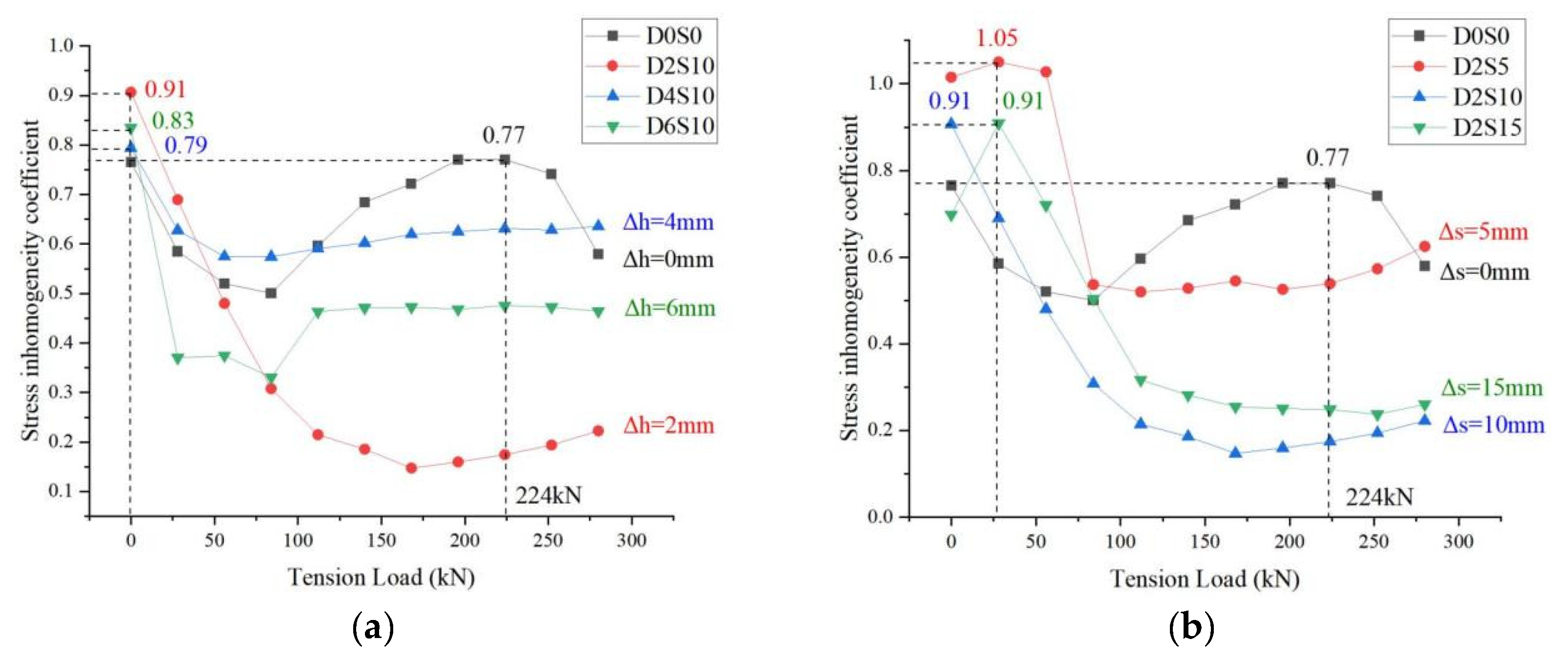
3.6. Analysis of Stress Inhomogeneity

From the load–strain curves of the specimen in Figure 8, it can be seen that the stress of the multi-tendon anchorage system shows obvious inhomogeneity. To study the varying regularity of the stress inhomogeneity with the test parameters, the coefficient η e is calculated as Equation (2).
η e = i = 1 n N i N ¯ 2 n 1 N ¯
In the formula, N i represents the force on the cable numbered i, N ¯ represents the average force of CFRP cables, and n represents the total numbers of CFRP cables in the specimen. Since the elastic modulus E i and cross-sectional area A i of each cable are the same, this means the inhomogeneity coefficient η e can be obtained directly from the strain. According to the formula definition, the larger the η e is, the stress distribution between the cable is more inhomogeneous.
The variation curves of η e of the specimen with different grooves are shown in Figure 12a. The average η e of D0S0 is 0.658, the average η e of D2S10 is 0.335, the average η e of D4S10 is 0.628, and the average η e of D6S10 is 0.472. Figure 12b shows the variation curves of the specimens with different groove spacing, the groove depths of which are 2 mm. The average η e of D2S5 is 0.68, the average η e of D2S10 is 0.335, and the average η e of D2S15 is 0.425.
Numerically, the stress distribution of the roughened specimens is more uniform than those without any treatment. The linear shape of D0S0 in Figure 12 shows that it decreases first and then rises, demonstrating that η e is affected by both the initial conditions and the increase in load. The curve of the grooved specimen initially decreases. However, despite the growing load, it is practically flat, indicating that after increasing the roughness of the second interface, the stress inhomogeneity of the cable is only affected by the initial conditions. At the same time, the influence brought by the increasing load is restrained. It can be seen both from the numerical value and linear shape that the roughness treatment helps reduce stress inhomogeneity. However, due to the interference of initial conditions, the quantitative relationship and specific regularity between the groove depth and spacing to reduce the are not obtained, which needs further research in the future.

4. Conclusions

A new inner cone + arc + straight bonded anchorage was designed for this study. The static stress test and finite element analysis were conducted on multiple specimens with varying sleeve groove depths and sleeve groove spacing. The study’s principal findings include an investigation of the anchorage efficiency and failure modes of the anchorage system with different groove design parameters, a comparison of the stress distribution difference between the new anchorage system and the conventional anchorage system, a discussion of the uneven stress distribution between the cables, and an analysis of the effect of the groove design parameters on this phenomenon. The specific conclusions are as follows:
  • In the new inner cone + arc + straight bonded anchorage system, the radial compressive stress on the CFRP cables and the extrusion stress at the contact interface is spread over the anchorage’s length more smoothly and uniformly. The radial compressive stress of the CFRP cable at the loading end of the new anchorage is only 89.2% of that of the inner cone anchorage and 38.8% of that of the inner cone + straight cylinder, which effectively relieves the stress concentration of the traditional anchorage. Additionally, the maximum axial displacement of the cable of the new anchorage is only 75.9% of that of the inner cone anchorage and 87.0% of that of the inner cone + straight anchorage, resulting in better anti-slip performance. In conclusion, the new anchorage improves the anchoring efficacy of CFRP cables.
  • The typical failure modes of the new type of anchorage system are interface slip failure, strand brittle fracture failure, and local strand stripping failure. During the loading process, the stress inhomogeneity is generated by variables such as the inconsistent length of the free section, the asynchrony between the deformation of CFRP and epoxy resin, and the eccentric force.
  • Increasing the roughness of the sleeve’s inner wall can enhance the anchoring efficiency. The second interface (epoxy resin–sleeve) was made rougher by creating grooves on the inner wall of the sleeve. After treatment, the anchoring effectiveness of all grooved specimens exceeds 90%. The groove parameters with the highest anchorage efficiency were h = 2, s = 5, with an anchorage efficiency of 98.55%. The deeper the groove depth and the denser the groove spacing, the higher the anchoring efficiency. The 2 mm to 4 mm groove depth can fully enhance the system’s anchoring capacity, while increasing it to 6 mm can increase anchoring efficiency by 10.39%. However, the gain in anchoring efficiency is not readily apparent as the groove depth increases. With a groove depth of 2 mm, 5 mm to 10 mm groove spacing may fully guarantee the anchoring efficacy of the anchorage system, with 5 mm specimens showing an improvement of 11.02% over those with untreated sleeves. FE simulations reveal that the sleeve’s inner wall roughness considerably affects the second interface contact stress, negatively associated with the groove depth. The groove spacing, however, is positively associated. The greater the compressive contact stress, the greater the likelihood of cable failure, which leads to a decrease in anchoring efficiency, suggesting that the radial force of the CFRP cable continues to govern the anchorage system.
  • The inhomogeneity coefficient represents the stress inhomogeneity of the system. It is shown that the reasons for the inhomogeneity of the multi-tendon CFRP anchorage system are the initial installation conditions and the increasing load, respectively. The mean value of the inhomogeneity coefficient of the anchorage system without roughness treatment is 0.658. By increasing the sleeve’s groove depth and encrypting the groove spacing, the inhomogeneity coefficient may be lowered to 0.335, thereby reducing the system’s inhomogeneity caused by the higher load. After adding grooves, as the load increases, the inhomogeneity coefficient remains stable without a significant increase, which effectively improves the anchorage efficiency of the multi-tendon CFRP anchorage system.
Concerning the inhomogeneity law of multi-tendon anchoring systems, more research is required in the future. In the meantime, the finite element model must be refined to represent the interaction mechanism between CFRP cables accurately. In addition, consideration must be given to the influence of prestress on the long-term performance of multi-tendon anchorage systems and the fatigue performance of the anchorage systems.

Author Contributions

Conceptualization, L.J. and X.C.; methodology, L.J. and Y.Y.; software, Y.Y. and X.C.; validation, L.J. and Y.Y; formal analysis, X.C.; investigation, Y.Y. and X.C.; resources, L.J.; data curation, Y.Y and X.C.; writing—original draft preparation, Y.Y.; writing—review and editing, Y.Y and X.C.; visualization, Y.Y and X.C.; supervision, L.J.; project administration, L.J.; funding acquisition, L.J. All authors have read and agreed to the published version of the manuscript.

Funding

This research was funded by the National Natural Science Foundation of China, grant number 51878488.

Institutional Review Board Statement

Not applicable.

Informed Consent Statement

Not applicable.

Data Availability Statement

The data generated or used during the study appear in the submitted article. Models and code that support the findings of this study are available from the corresponding author upon reasonable request (FE models and code).

Acknowledgments

The authors acknowledge NanJing Nuertai Composite Material and Equipment Manufacturing Co., Ltd. for providing the CFRP tendons.

Conflicts of Interest

The authors declare no conflict of interest.

References

  1. Jiang, Y.; Jia, L. Study on applicable spans and static performance of the sus-pension bridges using CFRP cables. Adv. Mater. Res. 2011, 255–260, 1115–1119. [Google Scholar] [CrossRef]
  2. Jiang, Y.; Jia, L. Contrastive analysis on limitation span between suspension b-ridge using steel and CFRP cable. Adv. Mater. Res. 2012, 568, 57–60. [Google Scholar] [CrossRef]
  3. Cai, H.; Aref, A.J. On the design and optimization of hybrid carbon fiber reinforced polymer-steel cable system for cable-stayed bridges. Compos. Part B Eng. 2015, 68, 146–152. [Google Scholar] [CrossRef]
  4. Meier, U. Carbon Fiber Reinforced Polymer Cables: Why? Why Not? What If? Arab. J. Sci. Eng. 2012, 37, 399–411. [Google Scholar] [CrossRef] [Green Version]
  5. Wang, X.; Wu, Z. Integrated high-performance thousand-meter scale cable-stay-ed bridge with hybrid FRP cables. Compos. Part B Eng. 2010, 41, 166–175. [Google Scholar] [CrossRef]
  6. Long, Y.; Kang, H. Analysis of 1:1 internal resonance of a CFRP cable with an external 1/3 subharmonic resonance. Nonlinear Dyn. 2022, 107, 3425–3441. [Google Scholar] [CrossRef]
  7. Liu, Y.; Zwingmann, B.; Schlaich, M. Carbon Fiber Reinforced Polymer for Cable Structures—A Review. Polymers 2015, 7, 2078–2099. [Google Scholar] [CrossRef] [Green Version]
  8. Liu, Y.; Gu, M.; Liu, X.; Tafsirojjaman, T. Life-Cycle Cost Analysis of Long-Span CFRP Cable-Stayed Bridges. Polymers 2022, 14, 1740. [Google Scholar] [CrossRef]
  9. Wang, X.; Xu, P.; Wu, Z.; Shi, J. A novel anchor method for multi-tendon FRP cable: Concept and FE study. Compos. Struct. 2015, 120, 552–564. [Google Scholar] [CrossRef]
  10. Cai, W.; Yu, B.; Zhang, J. Static Load Tests Study of improved Anchors for CFRP Tendon. IOP Conf. Ser. Mater. Sci. Eng. 2019, 490, 032008. [Google Scholar] [CrossRef]
  11. Zhuge, P.; Tao, G.; Jie, Z.; Ding, Y.; Wang, B. Optimal Design Method and Experiment for Improved Wedge-Type Anchors of Large-Diameter Smooth CFRP Tendons. Appl. Compos. Mater. 2021, 28, 1997–2019. [Google Scholar] [CrossRef]
  12. Hossein, H.; Aleksandar, V.; Alain, N.; Elyas, G. FE analysis and experimental validation of mechanical wedge-barrel anchors for CFRP rods. Compos. Struct. 2021, 275, 114509. [Google Scholar] [CrossRef]
  13. Ai, P.; Feng, P.; Lin, L.; Zhu, P.; Ding, G. Novel self-anchored CFRP cable system: Concept and anchorage behavior. Compos. Struct. 2021, 263, 113736. [Google Scholar] [CrossRef]
  14. Feng, P.; Zhang, P.; Meng, X.; Ye, L. Mechanical Analysis of Stress Distribution in a Carbon Fiber-Reinforced Polymer Rod Bonding Anchor. Polymers 2014, 6, 1129–1143. [Google Scholar] [CrossRef] [Green Version]
  15. Wang, L.; Xu, J.; Han, Q. Effects of Cross-Sectional Size and Shape on the Longitudinal Tensile and Anchoring Properties of CFRP Cables. J. Mater. Civ. Eng. 2019, 31, 04019053. [Google Scholar] [CrossRef]
  16. Zhuge, P.; Yu, Y.; Cai, C.S.; Zhang, Z.; Ding, Y. Mechanical Behavior and Optimal Design Method for Innovative CFRP Cable Anchor. J. Compos. Constr. 2019, 23, 04018067. [Google Scholar] [CrossRef]
  17. Zhu, W.; Chen, H.; Wei, W.; Chen, B.; Chen, X. Analysis of Multi-Tendon Friction-Based Composite Anchorage Device for CFRP Cables and Its Anchorage Mechanism. Materials 2022, 15, 2895. [Google Scholar] [CrossRef]
  18. Feng, B.; Wang, X.; Wu, Z. Static and Fatigue Behavior of Multitendon CFRP Cables with Integrated Anchorages. J. Compos. Constr. 2019, 23, 04019051. [Google Scholar] [CrossRef]
  19. Zhou, J.; Wang, X.; Peng, Z.; Wu, Z.; Zhu, Z. Failure mechanism and optimization of fiber-reinforced polymer cable-anchor system based on 3D finite element model. Eng. Struct. 2021, 243, 112664. [Google Scholar] [CrossRef]
  20. Zhou, J.; Wang, X.; Wu, Z.; Zhu, Z. A Large-Tonnage High-Strength CFRP Cable-Anchor System: Experimental Investigation and FE Study. J. Compos. Constr. 2022, 26, 04022053. [Google Scholar] [CrossRef]
  21. Zhou, J.; Wang, X.; Peng, Z.; Wu, Z.; Wei, X. Enhancement of FRP Cable Anchor System: Optimization of Load Transfer Component and Full-Scale Cable Experiment. J. Compos. Constr. 2022, 26, 04022008. [Google Scholar] [CrossRef]
  22. Kim, T.-K.; Jung, W.-T. Improvement of Anchorage Performance of Carbon Fiber-Reinforced Polymer Cables. Polymers 2022, 14, 1239. [Google Scholar] [CrossRef] [PubMed]
Figure 1. Section drawing of inner cone + arc + straight cylinder bond-type anchorage: (a) vertical section drawing of the anchorage; (b) comparison of the new anchorage’s transition section with the inner cone + straight cylinder anchorage.
Buildings 13 00669 g001
Figure 2. Three-dimensional perspective view of the anchorage: (a) internal perspective view; (b) external perspective view.
Buildings 13 00669 g002
Figure 3. Groove on the inner wall of the sleeve: (a) vertical view through the entrance of the sleeve; (b) dimension of the groove.
Buildings 13 00669 g003
Figure 4. Measuring points arrangement of anchorage system: (a) longitudinal arrangement; (b) transverse arrangement.
Buildings 13 00669 g004
Figure 5. Loading device of static tensile test: (a) loading platform, jack; (b) strain test acquisition system.
Buildings 13 00669 g005
Figure 6. FE model: (a) anchorage system without groove; (b) anchorage system with groove.
Buildings 13 00669 g006
Figure 7. Typical failure mode of specimen: (a) D0S0-anchorage zone; (b) D2S10-anchorage zone; (c) D4S10-anchorage zone; (d) D6S10-anchorage zone; (e) D2S5-anchorage zone; (f) D2S15-anchorage zone; (g) middle point of the free section; (h) cross-section of anchorage zone.
Buildings 13 00669 g007
Figure 8. Load–strain curve of specimen: (a) D0S0; (b) D2S10; (c) D4S10; (d) D6S10; (e) D2S5; (f) D2S15.
Buildings 13 00669 g008
Figure 9. Mechanical performance comparison of three anchorages: (a) radical compressive stress of CFRP; (b) extrusion stress of epoxy resin adhesive; (c) axial tensile stress of CFRP; (d) axial displacement of CFRP.
Buildings 13 00669 g009aBuildings 13 00669 g009b
Figure 10. Effect of groove depth on mechanical properties: (a) tensile test—anchoring efficiency; (b) FE analysis—contact compression stress of the first interface (CFRP–epoxy resin); (c) FE analysis—contact friction stress of the first interface (CFRP–epoxy resin); (d) FE analysis—contact compression stress of the second interface (epoxy resin–sleeve).
Buildings 13 00669 g010
Figure 11. Effect of groove spacing on mechanical properties: (a) tensile test—anchoring efficiency; (b) FE analysis—contact compression stress of the first interface (CFRP–epoxy resin); (c) FE analysis—contact friction stress of the first interface (CFRP–epoxy resin); (d) FE analysis—contact compression stress of the second interface (epoxy resin–sleeve).
Buildings 13 00669 g011
Figure 12. Variation curve of stress inhomogeneity coefficient: (a) η e of specimen group with different groove depth; (b) η e of specimen group with different groove spacing.
Buildings 13 00669 g012
Table 1. Material performance parameters of anchoring system.
ComponentElastic Modulus/GPaShear Modulus/GPaPoisson RatioCompressive Strength/MPaTensile Strength
/MPa
Shear Strength/MPa
Sleeve206770.30>300600
Epoxy resin adhesive2.60.35106.670
CFRP
(axial direction)
1507.20.27230070
CFRP
(radial direction)
10.57.20.0223070
Table 2. Specimen parameters of static tensile test.
Specimen NumberingNumber of Cables Groove   Depth   Δ h/mm Groove   Spacing   Δ s/mm Groove   Width   Δ s + Δ l / mm Number of GroovesLength of Anchorage L/mmExternal Diameter D/mm
D0S07000040093
D2S10721016.922240093
D4S10741023.841640093
D6S10761030.761240093
D2S572511.923140093
D2S15721521.921740093
Table 3. Summary of test results.
Specimen
Numbering
F c p u ( kN ) F p m ( kN ) η ( % ) Failure Mode
D0S0280.63316.1288.77%interface slip failure and local strand stripping failure
D2S10300.42316.1295.03%strand brittle fracture failure
D4S10307.05316.1297.13%interface slip failure
D6S10309.76316.1297.99%strand brittle fracture failure and local strand stripping failure
D2S5311.52316.1298.55%interface slip failure and strand brittle fracture failure
D2S15294.37316.1293.12%strand brittle fracture failure and local strand stripping failure
Table 4. Geometric parameters of three anchorages.
Type of the AnchorageInner Cone Segment Length L1/mmArc Segment Length L2/mmStraight Cylinder Segment Length L3/mm
New anchorage240.73209.2350
Inner cone + straight cylinder anchorage400——100
Inner cone anchorage400————
Disclaimer/Publisher’s Note: The statements, opinions and data contained in all publications are solely those of the individual author(s) and contributor(s) and not of MDPI and/or the editor(s). MDPI and/or the editor(s) disclaim responsibility for any injury to people or property resulting from any ideas, methods, instructions or products referred to in the content.

