1. Introduction
Reasonable setting of internal bracing is an important guarantee for the construction safety of deep and large foundation pits. Due to the temporary nature of foundation pit engineering, it is necessary to consider three factors including safety, economy and construction period in the design of a bracing system. A reinforced concrete structure is a traditional and mature support form for a bracing system. However, it has a long construction period of structure-forming and can easily cause excessive environmental noise and produce more construction waste after the bracing system has been removed. In recent years, engineering research companies in Southeast China have developed steel assembly bracing as a new type of bracing system. Compared with traditional bracing technology, its on-site construction period is short, and there are no noise and construction waste problems. Hence, steel assembly bracing is more environmentally friendly and has a wide application market in engineering.
As far as general engineering experience is concerned, even if the reinforced concrete structure is used as the internal support of a foundation pit, the influence of temperature on the internal force of the support must be considered when the length exceeds 40 m. Furthermore, the steel assembly bracing is more sensitive to temperature than the concrete bracing. Affected by higher thermal conductivity and lower specific heat capacity, the temperature of steel coated with dark antirust coating is usually higher than that of concrete in the same environment. The surface temperature of a steel structure bridge which is similar to steel assembly bracing in structural form is 15~20 °C higher than the environmental temperature, and the stress of each component is also different under solar radiation [
1,
2]. The steel inner brace of a supporting system will produce large additional axial force and axial deformation under the influence of environmental temperature [
3,
4]. In engineering cases, the method of covering the supporting system with the surface layer is sometimes used for thermal insulation treatment. Other studies related to steel truss structures show that the dynamic characteristics of steel structures will also change under the influence of environmental temperature, and even cause structural damage in severe cases [
5,
6,
7]. Therefore, the effect of temperature on the steel assembly bracing is significant and cannot be ignored.
Steel assembly bracing has been designed as one or multiple supports which consist of H-shaped steel parts [
8,
9], among which high-strength bolts are usually adopted to connect the steel. The compression bar analysis method of steel structure is used to design the bracing. Steel assembly bracing consisting of steel pipes or section steels has been used to support the vertical retaining wall structure around the foundation pit with a certain prestress applied in the axial direction of members to reduce the inward deformation. The study reported that the steel assembly bracing with appropriate prestress can significantly reduce the horizontal displacement of the retaining structure of the foundation pit [
10]. When the environmental temperature changes greatly, sometimes engineers even use steel diagonal assembly bracing for internal support [
11]. In fact, the axial force of each horizontal support transfers with the deformation of the retaining wall structure and becomes more complicated if the impact of environmental temperature is also considered [
12,
13]. With the increase of support length, the influence of temperature will become more and more significant. Sometimes it is even necessary to reinforce the soil near the support to ensure that there is no separation between the soil and the retaining structure when the support shrinks [
14].
Calculation of steel bracing of the foundation pit is usually based on the elastic foundation beam model to consider the effect of temperature, or based on the Winkler model to establish the empirical model of the effect of temperature on the bracing system of the foundation pit. Due to its complexity, inappropriate simplified models sometimes underestimate the temperature effect on steel bracing, which eventually leads to bracing failure [
15]. For steel assembly bracing, owing to the influence of lateral deformation along the depth direction of the foundation pit, the influence of temperature on the second layer bracing is sometimes greater than the first layer [
16]. In the low-temperature area of North China, the reduction of axial force caused by the temperature drop of steel bracing will also cause the additional deformation of the foundation pit retaining to the pit [
17]. Meanwhile, earthwork trucks can cause obvious vibration of steel bracing when they pass through concrete trestles near the end of steel bracing in which vehicle load, speed and distance are very important influencing factors [
18].
To the authors’ knowledge, at present, the research on steel assembly bracing is not enough and a safety real-time monitoring system has not been reported to be used to study steel assembly bracing. In the practical project studied in the paper, another problem also deserves attention: on-site technicians reflected that the vibration of the steel assembly bracing was sometimes obvious and thus complained about the insecurity. Therefore, the safety of steel assembly bracing under multiple working conditions is studied by the safety real-time monitoring system combined with numerical simulation in the paper.
2. Monitoring and Numerical Method
2.1. Technical Information of Foundation Pit Support
The size of the foundation pit of Huidong No.14 plot in Hangzhou City is 144 m × 215 m × 15 m, which is shown in
Figure 1.
Around the foundation pit, the reinforced concrete diaphragm walls and the triaxial cement-soil mixing piles form the lateral enclosure, steel assembly bracing are used in the horizontal direction, and some reinforced concrete purlins are used as trestle bridges on the earthwork transportation path.
Figure 1 shows the driving route of earthwork trucks at the foundation pit construction site and the plane layout of the steel assembly bracing. The transportation channel for the earthwork truck is closest to the steel assembly bracing T01. As can be seen from
Figure 2, there are upper and lower steel assembly internal bracings along the height direction of the foundation pit, and both ends are supported on the reinforced concrete trestle bridge for earthwork truck transportation. In addition, vertical steel lattice columns are set at a certain distance in the foundation pit to provide vertical support along the length direction of the steel assembly bracing.
In the process of excavating and transporting soil, the steel assembly internal bracing, which is also used as pedestrian passageway, has obvious vibration when earthwork vehicles drive through the pit. This phenomenon makes engineering technicians pay attention to the safety of the foundation pit. Because the project has been under construction, and the site project progress and working conditions are changeable, it is difficult for the traditional once-a-day monitoring technology to obtain axial force, temperature and support vibration data at the same time and realize safety early warning in case of an emergency. In this study, a real-time monitoring network is established by virtue of the wireless sensor monitoring technology in the construction site to support safety monitoring through real-time monitoring data.
2.2. Monitoring Points Locations
Steel tube internal bracing is a common form of the foundation pit, which has been widely used in a narrow and regular foundation pit. In order to monitor the safety of soil, buildings and structures, an underground pipe network and facilities around the foundation pit during excavation and construction of a deep and large foundation pit or special foundation pit, the designers must determine the safety monitoring points and monitoring contents of the steel pipe support in the design documents according to national standards, design documents and engineering experience [
19]. In this study, the monitoring experience of reinforced concrete support and steel tube support is used for reference, to set up the monitoring contents and layout of various measuring points for steel assembly bracing.
According to the site investigation, the vertical vibration of T01 reflected by engineers and construction workers can be obviously felt, especially when several earthwork trucks pass through the trestle bridge one after another. In order to master the relationship between the bracing vibration and running vehicle, and study its influence on the safety of the bracing system, the resistive dynamic strain gauges (precision ±0.1 με, range ±3000 με, type XKKJ-DTA100) and vibration acceleration sensors (sensitivity 0.3 V*s/m, range of scale 20 m/s
2, range of frequency 0.25~80 Hz, type BY-S07) have been arranged on the first track (initial pre-axial force
P01 = 3200 kN, compressive stress 18.22 MPa) and the second track (initial pre-axial force
P01 = 8000 kN, compressive stress 22.78 MPa) of T01 which is the closest to the trestle passage and has obvious vibration sense to monitor the dynamic response. Vibrating wire static strain gauges (strain: precision ±7 με, range ±1500 με, type T-900, temperature: precision ±0.2 °C (0~50 °C), range −40~60 °C, type CG-01) have been arranged on the surface of an H-beam because they are widely used in monitoring for foundation pit support and can be utilized to measure the steel surface temperature and surface strain of an H-beam at the same time [
20]. In addition, in order to analyze the correlation between vehicle and the response of structural dynamics, video surveillance is used to monitor earthwork truck transportation. A 5G network is used for wireless networking and remotely transmits data to the cloud database.
Figure 3 shows the locations and numbers of various types of sensors on the T01 steel assembly internal bracing.
As can be seen in
Figure 3, the vibration acceleration sensors are fixed on the beam for the reinforced concrete trestle, while all kinds of measuring points are installed on the upper flange of the H-beam for the steel assembly bracing. Ten dynamic strain measuring points (DSS-01~DSS-10) are arranged on the first steel assembly bracing, and six dynamic strain measuring points (DSS-11~DSS16) are arranged on the second steel assembly bracing. Two static strain measuring points (SSTS-01, SSTS-02) are arranged to master the static strain and steel temperature of steel assembly bracing. At the same time, acceleration sensors, numbered with 3AS-01 and 3AS-02, are arranged on the trestle bridge and steel assembly bracing, respectively. It is noted that the sampling interval of static strain and temperature data is 5 min; the sampling frequency of dynamic strain is 50 Hz; and the sampling frequency of vibration acceleration is 200 Hz.
According to the monitoring and analysis of real-time data for more than one month, the responses of vibration acceleration of the reinforced concrete trestle bridge and the steel assembly bracing are significantly larger when the earthwork truck passes through the trestle bridge, and the amplitude of vertical vibration acceleration on the first steel assembly bracing is larger than that of the concrete trestle bridge. In addition, the steel assembly bracing is obviously affected by environmental temperature. In order to analyze the influence of vehicle vibration and temperature on the safety of steel assembly bracing, the finite element method is adopted to analyze the structural responses under the combined action of vibration and temperature.
2.3. Numerical Method
In this section, a three-dimensional finite element method is adopted to analyze the steel assembly bracing via ABAQUS software. The calculation results can be used as a reference to compare with the results from the real-time monitoring [
21]. The finite element analysis involves modal analysis, steady-state thermal analysis and dynamic analysis. The vertical natural frequency and mode of the steel assembly bracing are obtained by modal analysis; the steady-state thermal analysis is used to analyze the temperature effect on the assembly bracing; the dynamic analysis is used to analyze the vibration effect of transport vehicles. Finally, the most unfavorable combination of temperature and vibration is considered to analyze the steel assembly bracing.
It should be emphasized that the highest temperature and the maximum vibration response of the vehicle driving during the monitoring period are simultaneously considered in the numerical simulation which cannot occur at the same time in practice. Therefore, the numerical simulation results in the paper will be conservative.
2.3.1. Numerical Simulation of Soil Layer
In order to consider the influence of the surrounding soil layer on foundation pit structure, the length and width of the soil layer are taken as four times that of the foundation pit size, and the thickness of the soil layer is taken as twice that of the foundation pit depth. The total size of the ABAQUS finite element model is set as 576 m × 860 m × 30 m [
22]. An eight-node C3D8R volumetric element is adopted for the soil layer and the number of elements is about 334,000. Considering that there is a concrete trestle bridge, concrete crown beam and diaphragm wall around the steel assembly bracing to be considered, a linear elastic model is adopted to simplify the calculation of soil layer parameters, which are shown in
Table 1. In the process of calculation and analysis, the soil layer adopts C3D8R element type with hourglass control. At the same time, in order to improve the calculation accuracy, the soil elements inside and around the foundation pit are encrypted, and the size of the elements far away from the foundation pit is gradually increased to improve the calculation speed. The bottom boundary of soil is constrained by three-dimensional displacement, the side of soil is constrained by normal displacement, and the upper surface is free. Because the mechanical properties of soil are usually little affected by environmental temperature, the temperature of the soil is set at a normal temperature of 25 °C.
2.3.2. Numerical Simulation of Supporting Structure
The supporting structure around the foundation pit is a concrete diaphragm wall with concrete C35 and a thickness of 1000 mm, which extends into the soil layer at the bottom of the foundation pit to twice the depth of the foundation pit by underwater pouring technology. A concrete crown beam is set at the top of the concrete diaphragm wall and a concrete structure is adopted for the purlin of the foundation pit with concrete C30. A steel crown beam and a steel waist beam are arranged along the vertical height of the steel assembly bracing. Both the crown beam and waist beam adopt the section steel with the same specification, i.e., H400 × 400 × 13 × 21 (Q355b), and the upright column also adopts section steel H400 × 400 × 13 × 21 (Q355b).
Based on the above situation, the S4R element, that is, a four-node curved thin shell element with hourglass control, is used for the diaphragm wall and the surrounding concrete purlin plate where the global element size is 1.0 m and the number of the elements is about 28,000. The B31 element, i.e., a two-node spatial linear beam element, is adopted in the model for the steel assembly bracing, steel purlin beam, section steel column and concrete crown beam in which the global element size is 1.0 m and the number of the elements is about 52,000. The thermal expansion coefficient of steel is α = 1.2 × 10
−5, the damping coefficient of steel is ζ
S = 0.02, and that of reinforced concrete is ζ
C = 0.02. The material parameters of each component of the foundation pit supporting structure are shown in
Table 2, and the finite element model is shown in
Figure 4. The outer soil and diaphragm wall have face-to-face contact, and the normal contact is set as hard contact which means that the normal pressure can be transmitted between the two contact surfaces only when they are not separated [
22,
23]. The penalty function is adopted in the tangential direction, and the friction coefficient is taken as 0.2.
With the help of engineering experience, it can be concluded that the stiffness of reinforced concrete diaphragm walls, cement mixing pile and reinforced concrete brace around the wall is much larger than the vertical stiffness of steel assembly bracing, and the low-order natural frequency of the foundation pit support system should occur in the steel assembly bracing, which has been also proved by numerical results. The low-order vertical natural frequencies of the steel assembly bracing system are mainly concentrated in (6.16 Hz~7.02 Hz), and the first four natural frequencies and the corresponding vertical vibration modes are shown in
Figure 5,
Figure 6,
Figure 7 and
Figure 8 as follows.
It can be found that the low-order natural frequencies of the steel assembly bracing are mainly concentrated on the T01 steel support shown in
Figure 1, and it is easier to cause T01 vibration when the earthwork truck drives over the concrete trestle bridge. The numerical analysis results preliminarily prove the problems reflected by construction workers.
2.3.3. Acting Load
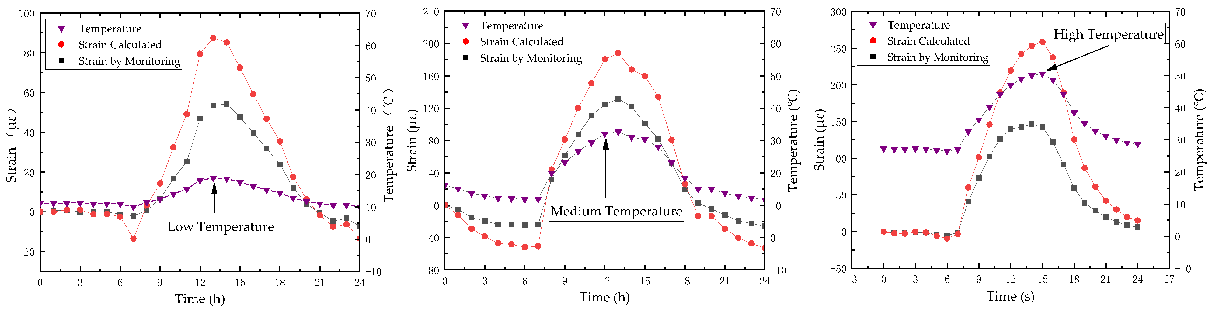
It has been proved that the internal force changes of steel bracing under the action of temperature cannot be ignored. Considering the abnormal vibration of T01 complained of by workers in this project, it is necessary to consider the combined action problem of temperature and vibration of the steel assembly bracing in both field monitoring and calculation analysis. When the site-monitoring system was established, the construction stage was in the binding steel bars and pouring concrete on the right foundation pit bottom plate near T01, while the left side was in the stage of outward soil transportation. Therefore, the working conditions of the construction site were complicated. As far as temperature changes are concerned, from August to November 2022, the 100 consecutive days of monitoring showed that the strain and temperature monitoring data of the steel assembly bracing changed little at night, while the steel surface temperature of the first steel assembly bracing of T01 ranged from 10.9 °C to 51.6 °C during the day, and the compressive strain of the brace decreased or increased with the temperature obviously. During the 100 days of real-time online monitoring, even in October when the temperature drops, for example, the lowest temperature of steel was 26.0 °C at 4 am on October 3, the highest temperature of steel was 51.6 °C at 14 pm, and the temperature difference between high and low was 25.6 °C. On that day, the axial static compressive strain SSTS-01 increased by 156.3 με with the temperature, and the similar high temperature environment frequently occurred within three months. The temperature changes of the steels from 12 August to 22 November is shown in
Figure 9.
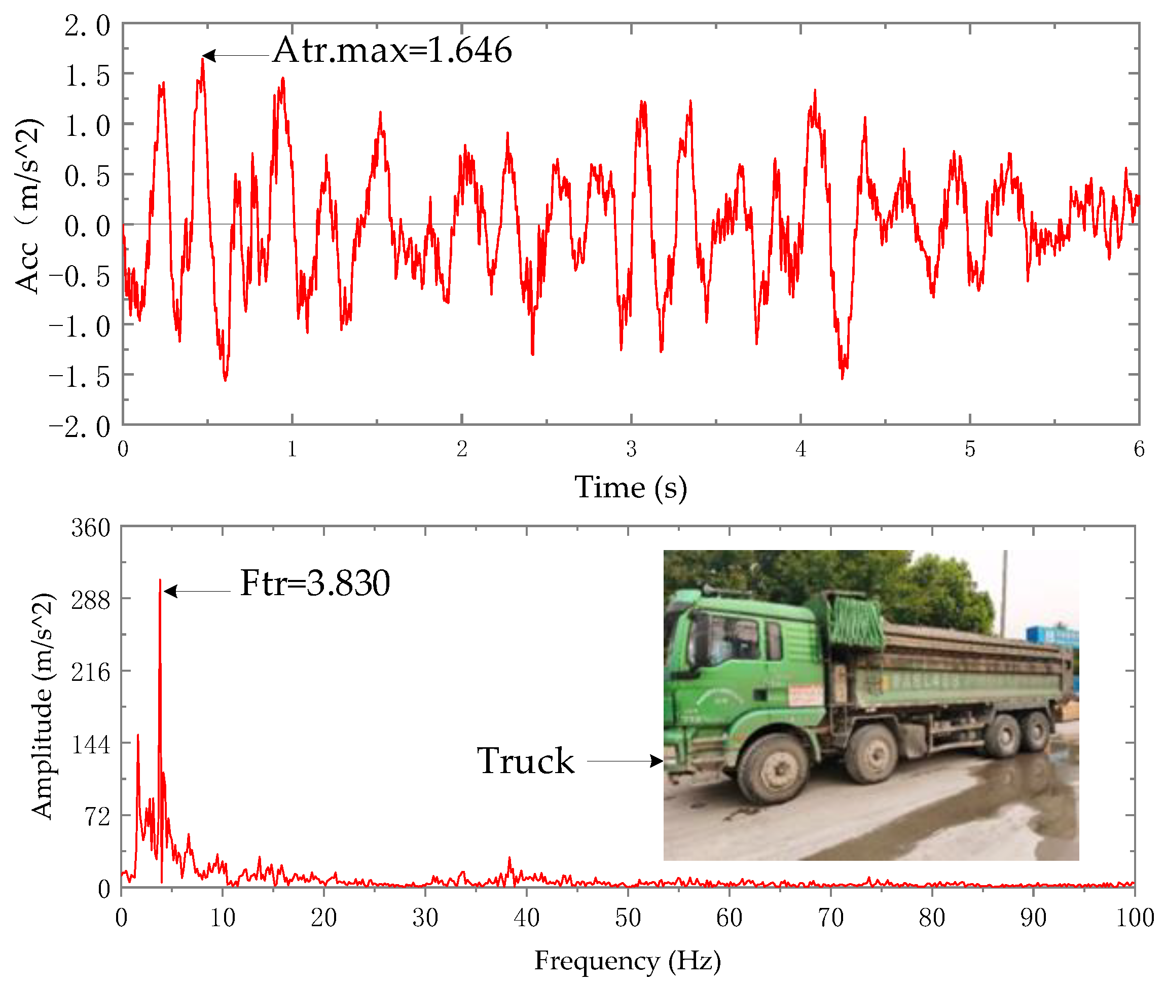
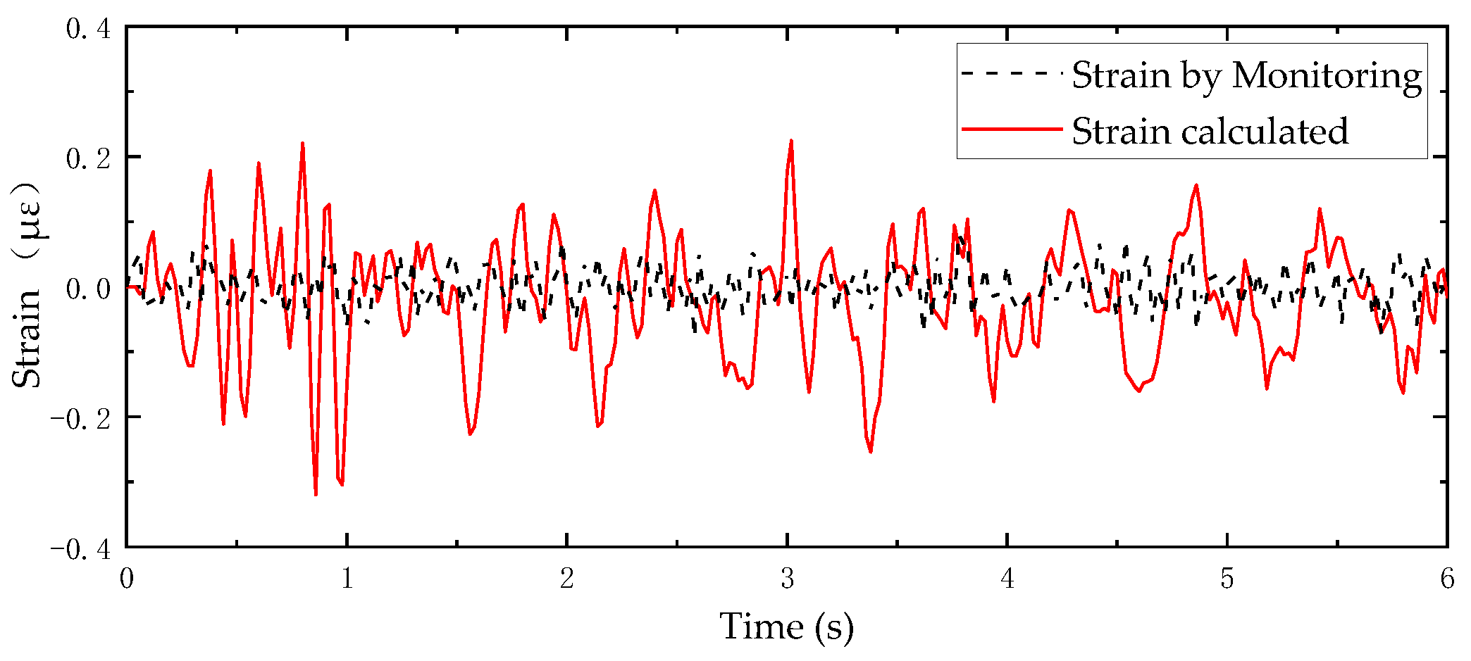
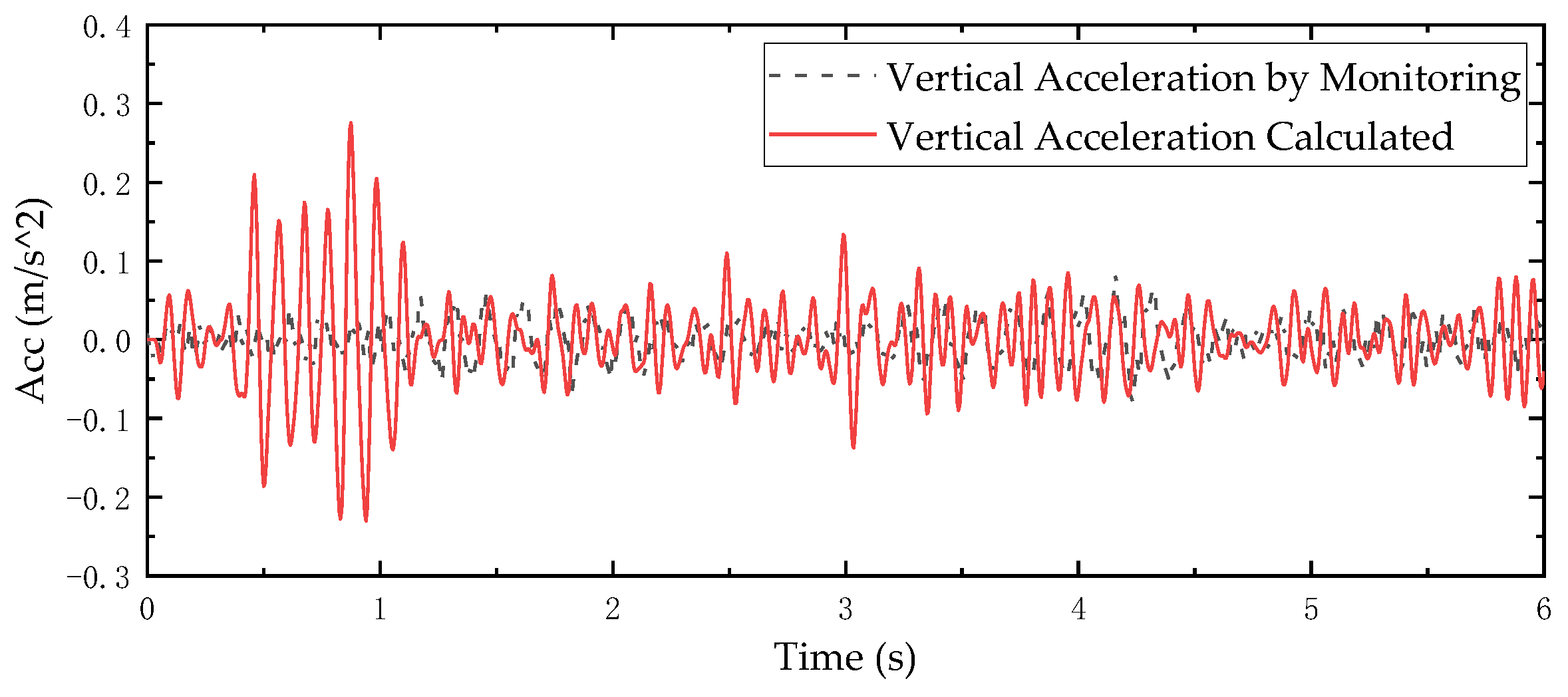
As for the vertical vibration problem of steel bracing, since the site is in the construction stage, the vibration sources of structure include: (1) the vibration caused by earthwork truck running; (2) the vibration caused by pouring concrete in the foundation pit bottom plate; (3) the vibration caused by tower crane running and hoisting construction materials, and vibration caused by various construction machines and tools. Frankly speaking, it is extremely difficult to accurately analyze the steel assembly bracing under the action of each vibration source. The multi-day vibration monitoring data show that the vertical vibration of the reinforced concrete trestle bridge and steel assembly bracing increases obviously when the earthwork truck passes through the trestle bridge, which further shows that the earthwork truck passing through the trestle bridge is the main reason for the significant vibration of T01. Video monitoring of the speed of earthwork trucks on the trestle is about 10 km/h. The truck is fully loaded and the roof soil layer is neatly covered, and the average total mass weighed is 20,000 kg. In order to obtain the moving load of the truck running on the trestle, a vertical vibration sensor is installed on one of the trucks to collect the vertical vibration monitoring data of the vehicle. The vibration action during the driving process of the vehicle is shown in
Figure 10 and
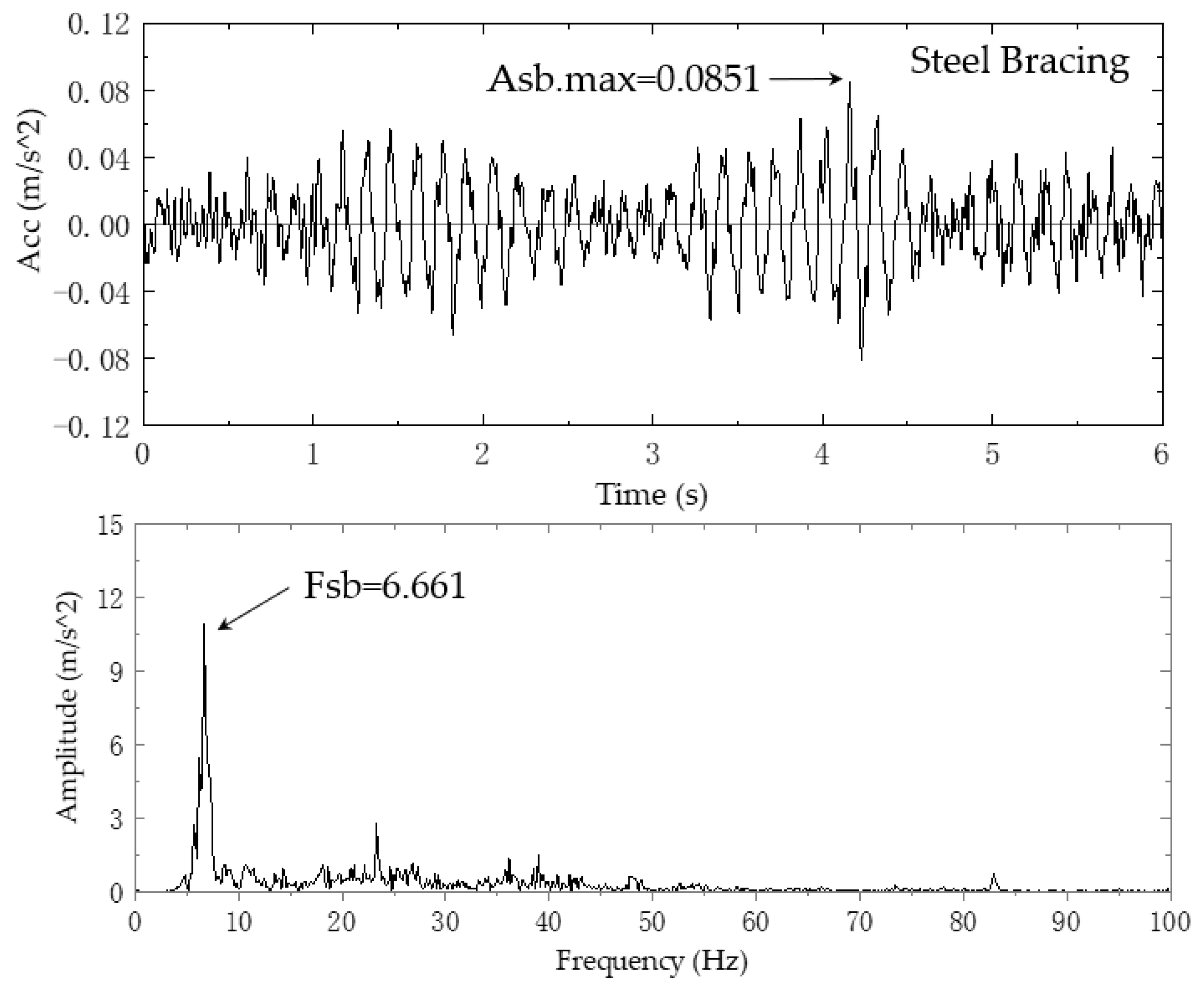
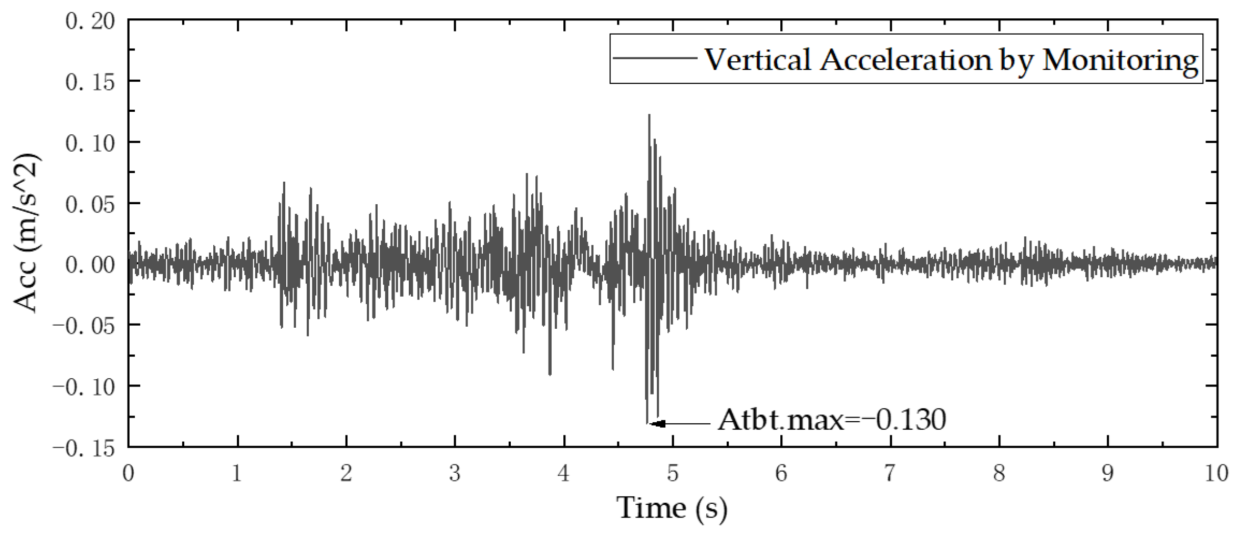
Figure 11 below. The vertical vibration responses of trestle ground vibration acceleration monitoring point 3AS-01 and steel support vibration acceleration monitoring point 3AS-02 at the same time are shown in
Figure 12 and
Figure 13. It can be seen from the vibration time history and frequency spectrum curves in
Figure 10 and
Figure 12 that the first-order frequency (
Figure 10) of the vehicle action when the truck passes through the concrete trestle is basically consistent with the first-order dominant frequency of the vertical trestle response. The trestle vibration contains forced vibration components, and the frequency components are complex. The first frequency of the vibration response in
Figure 13 is 6.661 Hz, which is close to the vertical natural frequency of the bracing in
Figure 7 of numerical analysis. The vertical vibration of the bracing is mainly caused by resonance.
During numerical analysis, the vibration effect of earthwork truck as the unique vibration source is considered and the static and dynamic strain of steel assembly bracing at the highest temperature difference are only considered. With regard to the vibration calculation input, the amplitude modulation input model of
Figure 10 is calculated based on the maximum value Atbt.max of the vibration response of the concrete trestle bridge (purlin) in
Figure 14, such that Atbt.max of
Figure 12 is equal to Atbt.max of
Figure 14. The time history curve of vehicle vibration acceleration after amplitude modulation in
Figure 10 was taken as the calculation input.
In order to simulate the influence of the vertical vibration of vehicles, eight concentrated forces are set in this model to represent the mass distribution of vehicles on the trestle bridge. The numerical values are calculated according to the vehicle weight and the vehicle mass distribution percentage. The first half of the earthwork vehicle accounts for 36% of the total mass of the vehicle, and the second half accounts for 64% of the total mass of the vehicle, and then the mass is evenly distributed to the concentrated force in the area located. During numerical analysis, the total mass of the vehicle is taken as 20,000 kg, and the front and rear wheels of the vehicle are distributed in proportion, in which the concentrated forces exerted by the front wheels RP-1 to RP-4 are all 1800 kg, and the concentrated forces exerted by the rear wheels RP-5 to RP-8 are all 3200 kg, as shown in
Figure 15. The time history curve of vehicle vibration acceleration after amplitude modulation is assigned as the amplitude curve which is multiplied by the above mass of the vehicle to obtain the dynamic load-time history curve. Finally, the dynamic load action can be analyzed. It is assumed that the most unfavorable working condition is considered, that is a linear combination of the maximum temperature difference of steel assembly bracing and the maximum vibration response amplitude of the trestle which occur at the same time.
4. Conclusions
As a new type of bracing system for the construction of deep, large foundation pits, steel assembly bracing has been gradually applied in the civil engineering field. In this paper, the effects of vibration and temperature of the construction site on steel assembly bracing of the foundation pit is studied by virtue of the safety real-time monitoring system and FEM technology based on an engineering case. The following conclusions can be drawn:
(1) The influence of environmental temperature on steel assembly bracing is significant and cannot be ignored. The axial compressive stress of bracing caused by environmental temperature even exceeds the prestress. Under the most unfavorable conditions, the stress caused is less than the yield strength of material Q355b, and hence the steel assembly bracing is in a safe state.
(2) The steel assembly bracing is made up of hundreds of H-beams of different specifications connected by high-strength bolts, and the bolt joints are easy to loosen due to construction vibration. Therefore, the working state of key joints of the steel assembly bracing should be checked regularly during construction. Meanwhile, the steel assembly bracing is under axial compression, and the out-of-plane vertical deformation has great influence on its stability. Accordingly, it is necessary to regularly monitor the out-of-plane deformation of brace.
(3) The vertical frequency-weighted vibration acceleration aw is an important indicator to reflect the comfort related with vibration. In this engineering case, this value of the steel assembly bracing aw = 79.30 dB, which is large. The reality is that on-site technicians complained about the insecurity of bracing vibration which is consistent with our theoretical analysis.
(4) The safety real-time monitoring system can be used as an effective way to analyze the steel assembly bracing under complex working conditions. The results of the paper can provide guidance for the systematic design and further application of steel assembly bracing in engineering.


