1. Introduction
In recent years, building design has evolved to include complex geometries and surfaces that are visually stunning and optimized for specific users. This transition refers to external architectural surfaces (typically wide), and interior surfaces, but even to individual “eye catching” components inserted within standard surfaces. The shift towards bespoke optimization approaches has necessitated a move away from standardized systems and components to single-use, customized, and optimized solutions. This concept has also been supported by the European community through the “new European Bauhaus” [
1], which aspires to imagine and build a sustainable and inclusive future together that does not exclude the esthetical aspects.
A direct consequence of this concept is also the growing alienation from standardization through the production of custom, or bespoke, architectural surfaces in small quantities, even if it may present relevant challenges for designers and manufacturers. With the rising demand for designs with proposed complexity, architects and designers are increasingly seeking unique solutions that are optimized for individual projects and user needs [
2]. However, existing manufacturing processes, developed to fit the mass production paradigm, are often unable to conveniently create complex shapes and surfaces in small quantities, from both economic and sustainability viewpoints [
3,
4]. Indeed, in the frame of reference of the building sector, one of the main limitations faced by small-scale production for custom or bespoke architectural surfaces or claddings is choosing an appropriate production method [
5]. Depending on the specific design, certain manufacturing processes may not be able to achieve the intricate shapes and forms required by architects and designers, further limiting the possibilities for customization. In such a context—mainly relating to small-scale production—the interest in and possibility of reusing artefacts, a sustainable process related to the principle of Design for Disassembly and Deconstruction (DfD) [
6], thus unfortunately becomes secondary.
To address these challenges, designers and manufacturers are exploring new materials and manufacturing processes that can enable the production of complex shapes and surfaces in small quantities. These technologies often incorporate new materials (e.g., composites or advanced polymers) and employ digital fabrication techniques that enhance precise control over the manufacturing process.
The increasing popularity of digital fabrication techniques has not only led to the development of new technological applications but also brought about a paradigm shift in production, as seen in the rise of the do-it-yourself (DIY) movement [
7].
Actors within these communities actively advocate for broader applications and the implementation of digital fabrication and bespoke alternatives, often highlighting their potential for higher sustainability and cost-effectiveness compared to traditional production methods. However, many of these technologies have not been comprehensively studied from a sustainability perspective [
8,
9], indicating the need for further research on this topic. Moreover, advanced customization enables the introduction of highly specific architectural solutions related to the ability to use flexible, digitally controlled machinery and the growing industrial capacity to change production models [
10].
In the context of construction, the concept of advanced customization and new fabrication techniques leads to a twofold development. On the one hand, it seeks to improve the quality and originality of buildings using digitally controlled tools; on the other hand, it fulfils the demand and needs for ambitious constructions.
Nevertheless, in small-scale production, the sustainability of the manufacturing process has not yet reached its potential, or a desirable level [
11]. Conventional manufacturing techniques typically involve high levels of energy consumption, resource usage, and waste generation, which can have a significant impact on the environment. As the demand and need for sustainable building materials and processes continue to increase (UN Sustainable Development Goals number 9 and number 12) [
12], there is a need for innovative technologies that enable the sustainable and efficient production of custom or bespoke architectural surfaces.
The successful realization of a concept from its conceptual stage to its tangible form is fundamentally dependent on the performance of the utilized manufacturing technology. Consequently, enhancing the capabilities of the available manufacturing technologies broadens the spectrum of possibilities that can be incorporated into a design. This expansion of technological scope directly influences the versatility and complexity that can be achieved in design implementations.
This study addresses the current restraints of consolidated digital manufacturing technologies in handling complex double-curvature geometries, focusing on the analysis of a novel technology called Cement–Textile Composite (CTC) [
13,
14,
15].
In particular, a comparative analysis is performed on the carbon footprint via Life Cycle Assessment (LCA) analysis between CTC, computerized numerical control (CNC) milling, and 3D printing. The focus of the present study is to estimate the potential of CTC technology in reducing carbon emissions during the production of complex surfaces for building envelope cladding solutions. It aims to strengthen the role of CTC in increasing designers’ capabilities to handle complex geometries while also considering the overall sustainability of the applicable design process. A parametric approach is used to assess these digital manufacturing processes and compare them within a generalized framework of analysis.
2. State of the Art—Review of the Main Processes
The contemporary design industry is witnessing a consolidation in the transformative shift towards parametric design practices. This approach, characterized by the use of algorithms and computational models, enables the creation and manipulation of complex geometries, and starting from the 2000s it revolutionized traditional design methods. The language of parametric design gained relevance in past years, and the resulting practice is rising in popularity among both professionals and customers [
16]. Parametric design has also served as the conceptual foundation for an entire architectural and design style known as ‘Parametricism’ [
17] and, although the definition is not without criticism [
18], this fact can serve as important proof in understanding the overall influence of the parametric design paradigm in the contemporary design landscape [
19].
Parametric design is often associated with the implementation of complex geometries, which may ultimately overflow in the manipulation of non-Euclidean geometries, such as elliptic, hyperbolic, and fractal geometry [
20], or other complex forms of geometrical shape definition based on organic and non-standard configurations [
21]. In this regard, the parametric design approach is enabled by the use of specific digital technologies, which allows for the effective modelling of the designers’ intentions.
Michael J. Ostwald outlined the overall historical development of architecture as a form of parallel evolution between the design process and enabling technologies. From this perspective, an enabling technology (ET) is any set of tools, techniques, or protocols necessary to support a given design process [
22]. Accessibility to suitable technology is, therefore, a critical factor in assessing the feasibility of a design process; sometimes, the infrequent implementation of specific design features is not due to a lack of appreciation or demand, but rather due to the limitations of the available technology, the high production costs, the scarcity of machinery, or a shortage of skilled professionals. These ultimately hinder the overall feasibility of that specific choice.
Pertaining to this, double-curved surfaces could be accounted for alongside the design features that are infrequently addressed in design practices; these are widely appreciated and have been successfully implemented within a variety of successful high-budget designs, most notably as the basis for the building envelope design [
23]. This paradoxical situation can be attributed to ETs. While the double-curvature design can enhance the overall aesthetic and functional aspects of a project, its practical realization requires access to sophisticated machinery and a highly skilled workforce. Consequently, this design strategy necessitates significant financial investment, which may render it less viable for smaller-scale projects where resources are more limited [
24]. To solve this gap in the research, in recent years, ETs have been thoroughly researched in the form of digital manufacturing technologies.
In the framework of building envelope design, the outer appearance of a building is often achieved via the implementation of a cladding system. A cladding system allows the application of one material over another to provide a skin, or layer, over the building to define both its outer shape and finishing material [
25]. In addition, non-loadbearing claddings can be implemented as a system where outer lightweight panels are used in conjunction with an inner structural framework [
25]. This setup allows one to freely define, up to a certain extent, the overall shape and material of the non-structural panels, where the typical materials of choice may range among the following alternatives: brick, stone, metal (aluminium or steel), timber (wood), glass, concrete, ceramic tiles, vinyl siding, fibre cement, and different composite materials (aluminium composite panels, fibre-reinforced plastic) [
16,
25,
26].
Multiple manufacturing processes have been developed to enable the production of cladding panels with different geometries either planar or three-dimensional. In the case of three-dimensional shapes, these can include various types of geometries such as meshes of planar polygons, or curved surfaces with both single and double curvature. A building design that implements complex cladding geometries is generally referred to as a “free-form” construction.
As previously implied, free-form construction often stands on the liminal edges of current technological capabilities, resulting in highly complex manufacturing needs. In particular, due to the complexity involved, the overall sustainability of free-form construction is often questioned [
27]. Kavuma et al. noted that free-form projects can easily run behind schedule and over budget, suggesting that the fabrication of free-form components has a large impact on the timely completion; instead, over-costing issues are dependent on factors related to the personnel involved [
28]. Essentially, because free-form buildings are achieved via extremely complex manufacturing processes, the whole production displays less flexibility in overcoming different kinds of contingencies, such as client decisions, delays, or project changes. Any form of such uncertainty can easily result in cost and time overruns.
The manufacturing process for free-form building envelopes usually focuses on the outer panels, which are designed in a process that has been named “panelization” [
29].
Panelization aims to simplify free-form geometries into a finite series of sections (panels), which can be individually manufactured and assembled on site. The panel geometry is usually planar, and it is achieved via different techniques (e.g., triangulation, primitive approximation, fitted rotational surfaces, principal curvature meshes, developable strip model [
29]) deriving from an overall approximation of the proposed design.
However, the manufacturing of panels with a true free-form three-dimensional geometry (e.g., double curvature geometry) can also be achieved via a limited number of manufacturing technologies, particularly digital manufacturing technologies that implement CNC production machinery.
Materials suitable for panel production include plastic, glass, metal [
30], and different groups of specialized materials, such as a fibre-reinforced polymers (FRPs) [
31]. Metal panels are generally produced via bending, die forming, single-point forming, dieless forming, and other similar processes [
30]. However, cold bending methods cannot produce precise double-curvature geometries above a certain degree of complexity [
32]. On the other hand, advanced materials like glass and fibre-reinforced materials such as fibre-reinforced plastic (FRP) and glass-fibre-reinforced concrete (GFRC) require production processes that involve the use of moulds [
30]. In such cases, moulds are required to shape raw materials into their final forms. However, this necessitates a shift in focus towards the production, utilization, and waste generated by the mould implementation [
33]. Free-form moulds are generally produced via digital manufacturing machinery implementing both subtractive and additive methods. In this context, the novel research approach based on the proposal of no-mould processes aims at lowering costs and increasing the sustainability of free-form panel production by reducing assembly wastes [
34].
2.1. Traditional Production Processes
Multiple production processes enable the realization of complex shapes and are typically related to factors previously described. Within this context, the macro-processes most relevant to the construction sector have been selected: forming, casting, CNC milling, and 3D printing.
Table 1 provides a schematic overview of the multiple variables’ respective ratings. Specific technologies have been presented for each macro-process category.
The comparison enabled via this synthetic comparative review highlights FDM and CNC milling as the technologies that exhibit a higher degree of overlap with CTC across various analytical dimensions, suggesting that the three technologies may share similar applications.
The initial CNC milling process employs a computer to mill, cut, and shape materials like plastic, metal, stone, and expanded polystyrene (EPS). CNC milling has also been utilized to produce moulds for free-form panels and large-scale components [
34]. The material used for producing the mould may vary, with reported cases of application of rigid foams, polymers, metals, wood, and clay. It is important to note that more sustainable solutions, like clay, may pose specific limitations. For instance, the material’s low strength permits only a limited number of reuses for the same mould [
31], leading to a higher frequency of replacement, and consequently fabrication. In this regard, more stable alternatives like PVC, PUR, and XPS provide a wider range of applications but, overall, display poorer environmental sustainability. The fabrication process is possible both in the factory and on site [
35]. This process typically consists of three main steps:
Digital modelling: the digital model is converted in the format required by the CNC machine using specific software.
CNC milling: the foam is milled initially by coarse milling and then through fine milling.
Surface treatment: the surface is manually treated with the coating and then sanded to obtain a smooth surface.
The 3D printing FDM method is part of the “additive manufacturing approach” and is increasingly common for the creation of customized elements. It manipulates an object in its digital format by adding several layers back-to-back and the fabrication of components can be performed either on-site or in the factory [
36,
37]. It is based on the extrusion of a molten material that hardens immediately after the deposition. This technology is unique in its ability to produce very thin shells geometrically precise on a large scale [
36,
37].
Within the presented frame, additive manufacturing technologies can also be implemented both to directly produce free-form architectural panelization or the necessary moulds. However, it is very complex to discern the technology with the lower environmental impact. Faludi et al. developed a comparative LCA assessment about the use of two specific machines for subtractive and additive production. While it is not possible to draw a clear line to define the most sustainable solution, it is instead possible to broadly outline a series of trends [
38]. Considering the machines as frequently utilized (which is a basic premise to balance the embodied impacts of each machine), the impact of 3D printers is generally dominated by energy use, while CNC material waste becomes more dominant with increased use.
Overall, the main phases of the process are:
Design modelling: the element is digitalized with a specific software.
Transmission of the script from the software to the machine.
3D print: layer-by-layer deposition of the material.
Surface treatment: the rough area of the print due to the deposition is smoothed [
35]. The primer is applied and a painting process follows.
2.2. Innovative Production Processes: Cement–Textile Composite (CTC)
The Cement–Textile Composite is a low-cost and expeditious system to produce complex customized façades with the possibility of having personalized finishes (surface texture, colour, transparency, grass, etc.), and programmable performance (structural resistance, transparency, etc.). Thanks to CTC, it becomes possible to build custom façades with double curvatures, exploiting the properties of the material; additionally, thanks to the integrated custom-developed configurator that allows designers to create complex shapes and geometries, the material has potential to fulfil precise functions. The patented technology [
13,
14,
15] is based on a cement matrix (cement, water, and polymer fluid) coupled with three-dimensional deformable fabric. The surface fabrication does not require ad hoc formwork or moulds for forming (standard concrete formworks comprise around 40% of the construction cost [
39] but a simple tensioning frame, meaning a fast and cost-effective forming process. The technology enables the preservation of the utilized fabric finishes. Moreover, various types of cement can be employed in the construction process, including white, traditional, coloured, high-strength, or environmentally friendly variants. The envisaged production treatments and processes encompass the capability to retain the visible geometric texture, colour, or pattern of the fabric. Additionally, if needed, it is feasible to ensure the tactile perception of the material, such as softness, soft touch, or a velvet/talc-like effect, without necessitating subsequent post-installation treatments. In one of the production variants, is it possible to locally remove the cement matrix to create discontinuous or semipermeable (i.e., to air and/or light) surfaces.
The manufacturing process of CTC (fully described in patents IT102019000005300A, IT102016000128119, and EP3990720A1 [
13,
14,
15]) is designed to address the main potential environmental benefits of digital manufacturing technology [
8], such as improved resource efficiency and shorter supply chains. It also aims to mitigate production issues that could negatively affect the implementation of complex geometries in design, such as the cost overruns typically associated with their production [
24]. Agusti-Juan et al. proposed that digital fabrication maximizes its potential environmental benefits when the technology is applied to pursue resource efficiency and functional optimization [
10]. Functional optimization is defined as the integration of additional functions within the realised object, such as increased performance (e.g., thermal or acoustic) or simultaneous uses of the same object for multiple purposes (e.g., structural elements which may double as furniture). In this regard, the shell-type objects developed via CTC inherently minimize the material use for the finished product. Also, CTC effectively avoids the use of moulds in favour of support frames, which can be designed for optimized material consumption, while also allowing effective reuse at the end of its operational implementation. Additionally, the hollow interior of CTC products can easily be implemented to fit additional functions, either by housing extraneous applications (e.g., machinery or sensors), or masking and covering existing elements in the environment which may need concealment.
Furthermore, CTC seeks to improve social impact by envisioning more localized production, introducing innovative distribution models, and fostering new collaborations through seamless integration into existing production landscapes.
3. Method
The Life Cycle Assessment (LCA) method was used to quantitatively estimate the potential carbon saving resulting from the generation of complex surfaces, allowing us to identify the main driving parameters of the production processes and compare the results for different domains, as explained later. The adopted method for the carbon footprint assessment is based on International Standards ISO 14067 and EN 15804 [
40,
41].
The method adopted for the climate change evaluation is the Global Warming Potential (GWP) assessment, according to the IPCC-2013 method [
42]. All the GWP values will be expressed on an equivalence basis concerning CO
2, in kg or tons of CO
2 equivalent.
In this study, digital manufacturing processes, namely CNC milling, FDM 3D printing, and CTC, are compared for their expected environmental performance in producing similar target geometries with double-curvature properties.
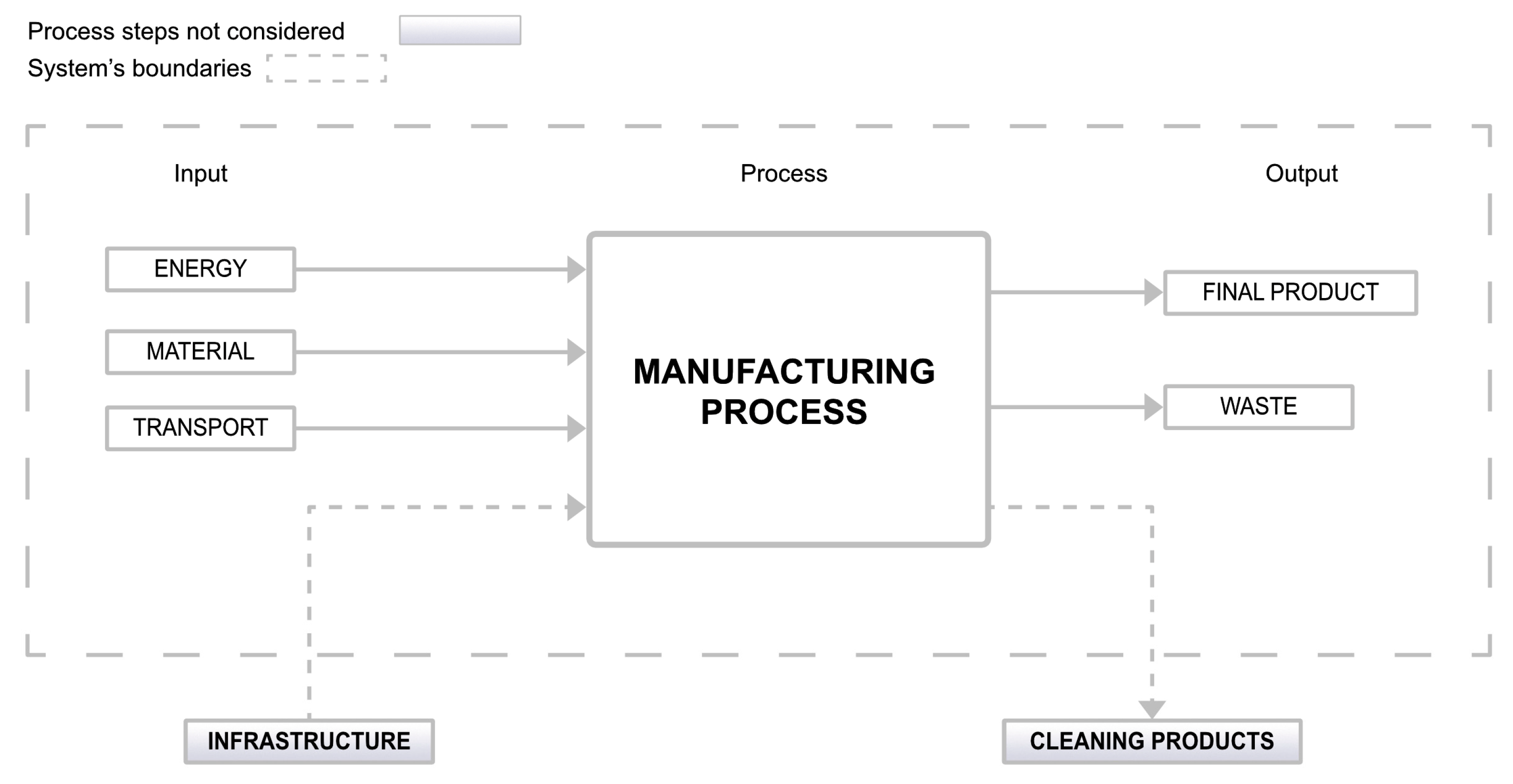
The boundaries of the system for the LCA are shown in
Figure 1. The analysis implemented is a “Cradle to Gate” analysis, so the initial stages of the element production process are assessed starting from the sourcing of raw materials to the completion of the production stage in the factory.
As shown in
Figure 1, the analysis takes into account the raw material used, the pre- and post-processing transportation methods, and the energy used. On the other hand, the infrastructures, the materials used for cleaning, and the relative impact of the labour employed were not considered.
For each screened scenario, it is assumed that the main campus of “Politecnico di Milano” is the final destination for the product to be installed and utilized. Data from Ecoinvent v.3.9.1 were used to model the processes and SimaPro 9.5 was adopted as a tool for the analysis (based on the considerations that follow). Whenever possible, country-specific processes and processes relevant to Europe were selected. Each process involves inputs which concern materials, transportation, and infrastructure and, consequently, the outputs in which waste is included as well as the final product.
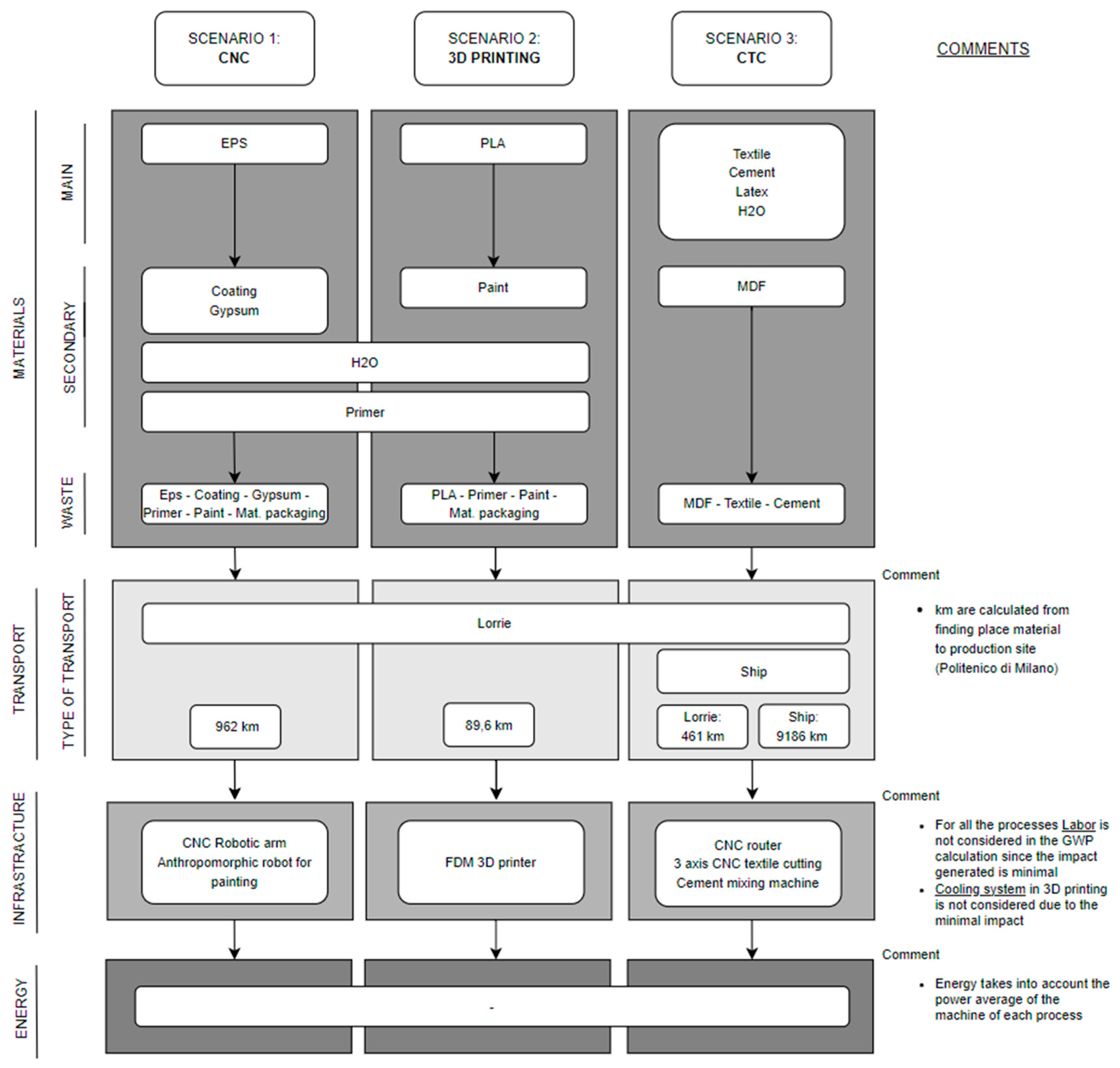
Figure 2 shows the assumptions for each production process detailed described in the following sections. As shown in the results section, all the quantities (materials and energy) will be different on the basis of the domains of the area considered for the various technologies.
In order to ensure that the analysis would be parametric, it was decided to identify domains (described in detail in the subchapter “Parameterization and domains”) to compare the carbon footprint of the three pre-described selected production processes in such a way that the analysis carried out is not tied to one or more case studies but applies to multiple forming requirements. Further attention was given to the three production processes, as they are based on very different principles:
CNC milling is based on material subtraction.
Three-dimensional printing FDM is based on material addition.
CTC is based on morphing a membrane, considering material relaxation under the minimum curvature hypothesis.
The inherent distinctions among production processes have underscored the need for establishing a methodology that facilitates a practical and dependable comparison. This is particularly crucial within a field where the primary aim is not to confine the analysis to a specific case study but to develop equivalent nomograms for expeditiously ascertaining the most advantageous process from a Life Cycle Assessment (LCA) perspective, applicable across various domains.
The methodology identified starts from the target shape, which is treated differently for each of the processes, namely the following:
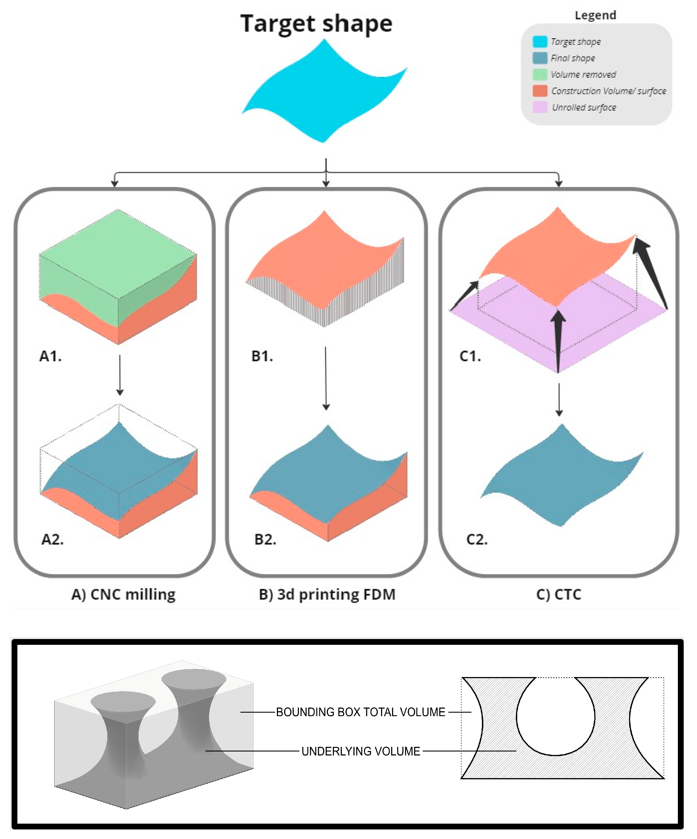
CNC milling: In the case of CNC milling, which is a subtractive process, the initial step involves the creation of a bounding box (BBOX) encompassing the entire target surface, as presented in
Figure 3. This BBOX serves to determine the total volume of material needed for the machining process. For the paper, we considered a polystyrene (EPS) block as the material to be milled. Subsequently, a portion of this material is removed during milling, and considered as waste, while the remaining portion shapes the final required form. The resulting volume and its surface are later coated with an acrylic enamel hardened through a catalyst. Then, a gypsum-based plaster and a painting are applied for finishing. The ratio of the remaining volume to the total volume is referred to as the underlying volume (UV) expressed as a percentage filling of the BBOX. This percentage value allows for the comparison of different potential surfaces, which, from a process perspective, have an equivalent impact. Consequently, the surface dimensions are scaled down accordingly.
Three-dimensional printing FDM: For the sake of comparison and similar to CNC milling, the process of 3D printing FDM involves defining a BBOX and the same UV as a percentage filling of the BBOX as presented in
Figure 3. However, since 3D printing is an additive process, the saturation percentage is determined by the volume enclosed by the final surface (essential for generating the surface), equivalent to the volume not removed during CNC milling. The final volume generated is then finished with a primer and a painting process.
CTC: In the case of CTC, the focus is on the surface itself, without employing a volumetric analysis approach. Dimensioning and determining parameters in this context are more intricate, as the outcome is directly related to the surface itself. Additionally, the generation of a surface with double minimum curvature, starting from a planar fabric, involves stretching, making the calculation more complex. Consequently, a genetic algorithm was developed to generate surfaces with double minimum curvature for three different type-generation families. This approach facilitated the determination of area values for the CTC system across various dimensional domains. To enable comparison with the other two processes, the obtained results were then correlated with the initial area, aligning them with the concept of BBOX and underlying volume (UV), as presented in
Figure 3. In this case, the CTC membrane follows the external shape of the UV, with a low thickness.
3.1. Parameterization and Domains
The analysis presented is a preliminary stage that identifies the most appropriate process for different domains. Hence, a decision was made to incorporate the notion of the “domain of relevance” to appropriately scale the evaluation. Consequently, this approach ensures that the analysis remains applicable beyond a specific case study, effectively extending its validity. The reference volume is a BBOX, which can identify a variety of final product shapes. Unlike a static shape, this reference volume is dynamic and can be modified through the adjustment of specified geometric variables. This approach enables the parametric compilation of Life Cycle Assessment (LCA) computations for a diverse range of production scenarios. This type of assumption is made since the study aims to analyse generic cases for the sake of a comparison between several ranges for small customizable objects. The X and Y directions are constant for each case scenario.
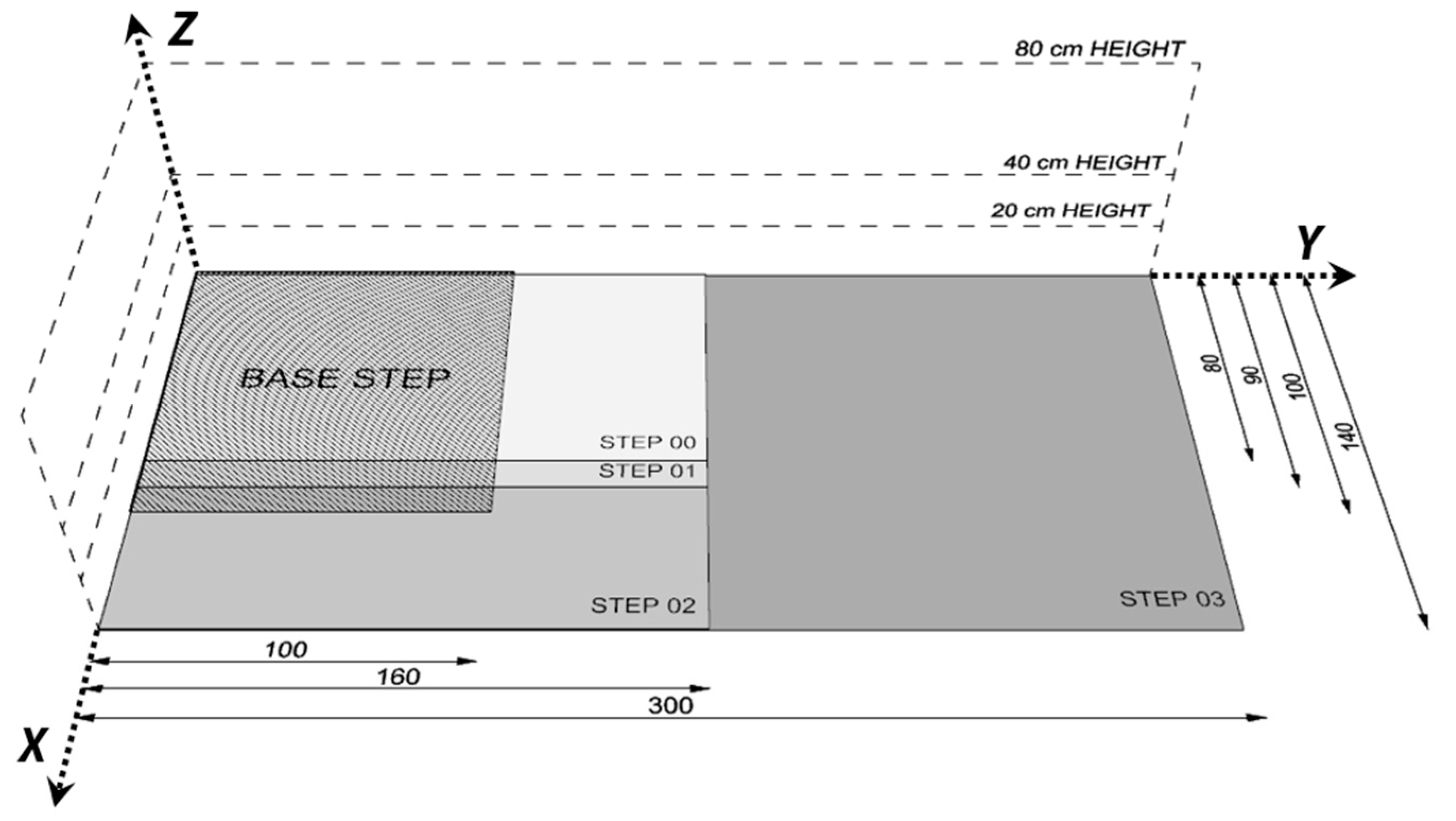
For the third direction (Z), three distinct BBOX heights are considered in each scenario, with values of 20 cm, 40 cm, and 80 cm, respectively. The GWP trend for each process is then defined.
In the end, all the cases are compared with several percentages of saturation to evaluate the net value of the percentage volume fill of a BBOX, encompassing a general element with general shapes. As it is possible to see in the following sections, the analyzed percentages have a constant increment of 20%, from 0% (empty) to 80%. The total fill of the BBOX (100%) was calculated but it is not recorded in the results since it represents the maximum limit of the volume. The implementation methods of the three selected processes turned out to be very different from each other, so it was necessary to determine realistic methods of simulating each step: area, height, and filling.
The following analysis will compare three different shaping process alternatives. This choice stems from the fact that the other two technologies, 3D printing and CTC, have the printer area and the height of the fabric roll as constraints, respectively. It follows that, since the EPS block is the element with the smallest dimension, it was selected as the reference for defining the domains. The BBOX incremental step sizing process is considered as an EPS block of 255 × 100 × 100 cm (L × D × W) that is cut or glued to other complete or partial blocks to arrange the following geometries of the base plan.
The domains studied are as follows:
BASE STEP: 1.0 m × 1.0 m. This option was selected because it is the standard area in the construction sector.
STEP 00: 1.60 m × 0.80 m. This option was selected because it has a side ratio of 1:2, with a longer side length greater than half of the length of the reference EPS block.
STEP 01: 1.60 m × 0.90 m. This option was selected as variation of step 00, almost at the width saturation limit; this can demonstrate how a small change can impact the result.
STEP 02: 1.60 m × 1.40 m. This option was selected with its width greater than the block; consequently, a junction is required.
STEP 03: 3.00 m × 1.40 m. This option was selected with width and length greater than the reference block; as a result, junctions are required on both sides.
3.2. LCA Assumptions for CNC Milling
The assumptions originate from the need to find a proper method of dealing with the partitioning of an EPS block in such a way as to allocate proper importance to both the material used and the material recycled or discarded so considered in the “waste” section of the various processes. We have decided to evaluate, as an alternative for our analysis, only the EPS panel as an example of a standard material suitable for the purpose. It can provide excellent workability and suitable support for various finishes while ensuring lightness, cost-effectiveness, material availability, and easy composability of the basic units to create samples, even at a high volume. However, we have also analyzed wood and cork as alternatives; despite being natural and renewable materials, these often yield comparable or worse results as the size of the workpiece increases. This is primarily due to the materials’ density and the resulting transportation impacts at the same volume; additionally, the increasing number of glue joints required to ensure adequate processing volume is too great. The assumptions made for calculating the quantities of the material used have been schematically collated in
Table 2.
Table 2.
Description of the hypothesis considered in the computer numeric control (CNC) method.
Table 2.
Description of the hypothesis considered in the computer numeric control (CNC) method.
| CNC Milling |
|---|
| Name | Hypothesis |
|---|
| EPS | The volume of material used has been calculated assuming the use of single piece or multiple joint standard material elements (Figure 4).
If the volume considered does not coincide with the standard material size, then the volume considered refers to multiple standard pieces joined together.
Density: 25 kg/m3, [IPCC GWP 100a kg CO2 eq: 3.96] |
| Acrylic Enamel | The amount of material is calculated by considering the yield of the acrylic enamel and the different surfaces for each filling percentage.
The finishing is made up of a quarter of acrylic enamel.
Density: 1.05 kg/m3, [IPCC GWP 100a kg CO2 eq: 2.25] |
| Catalyst | The amount of material is calculated considering the yield of the catalyst and the different surfaces for each filling percentage.
The finishing is composed of three quarters by the catalyst.
Density: 1.05 kg/m3, [IPCC GWP 100a kg CO2 eq: 2.25] |
| Plaster | Gypsum has a yield of 1.75 kg/m2.
It is calculated considering that the latter is applied superficially.
[IPCC GWP 100a kg CO2 eq: 0.04] |
| Primer + Water | The primer is applied superficially; then, the total area and its yield are considered for the calculation (25 kg/m2).
The primer must be accompanied by a water solution; the ratio is one-eighth. [IPCC GWP 100a kg CO2 eq: 2.25 (Primer), 0.00002 (Water)] |
| Painting | Considering the total surface, concerning the filling percentage and the yield of the paint (12 m2/L), the necessary quantity was calculated.
Density: 1.1 kg/m3, [IPCC GWP 100a kg CO2 eq: 2.25] |
| Materials Transport | The distance from each semi-finished product manufacturer to the installation and realization location has been considered, which, for the paper, has been hypothesized to be Milan.
[IPCC GWP 100a: 0.51 kgCO2-eq/km (Lorry 3.5–7.5 metric ton)] |
| Energy | Consumption values for the milling machine and the mixing machine are, respectively, 5 W/h and 0.33 W/h.
[IPCC GWP 100a kg CO2 eq: 0.12] |
| Waste | For all materials, except for EPS, waste was calculated by taking the quantity rounded up minus the actual quantities used.
For EPS, the waste material was calculated considering the excess part taken to follow the cutting lines, and the material discarded during modelling (different for each SV of the BBOX).
The remaining part of the volume purchased (1 × 1 × 2.55 m) and the cutting line considered for each geometry are not considered scrap (Figure 3).
[IPCC GWP 100a kg CO2 eq: depends on the material] |
3.3. LCA Assumptions for FDM 3D Printing
This type of technology is related to digital manufacturing and among a multitude of 3D printing types. The Fuse Deposition Method (FDM) is considered; here, a printing nozzle deposits the melted and extruded thermoplastic filament layer by layer in the print area.
Overall, the process works with a unique primary material (polylactic acid—PLA) which is fused in the required quantity; therefore, waste sections are limited to a small quantity of PLA material and packaging of materials. Furthermore, the procedure also involves a cooling system which is not in the calculation of GWP. The whole calculation hypothesis used in the process is shown below in
Table 3.
3.4. LCA Assumptions for Cement–Textile Composite (CTC)
The quantification of CTC materials consumption presents a specific challenge within the context of the BBOX hypothesis in comparison to other manufacturing technologies. This arises from the inherent hollowness of CTC products, determined by the fact that materials consumption is predominantly concentrated within the thin shell of the product and the tensioning frames incorporated in the forming process. In this context, the frame assumes a pivotal role in facilitating the precise tensioning and shaping of textiles. The frame is assembled from planar wooden components.
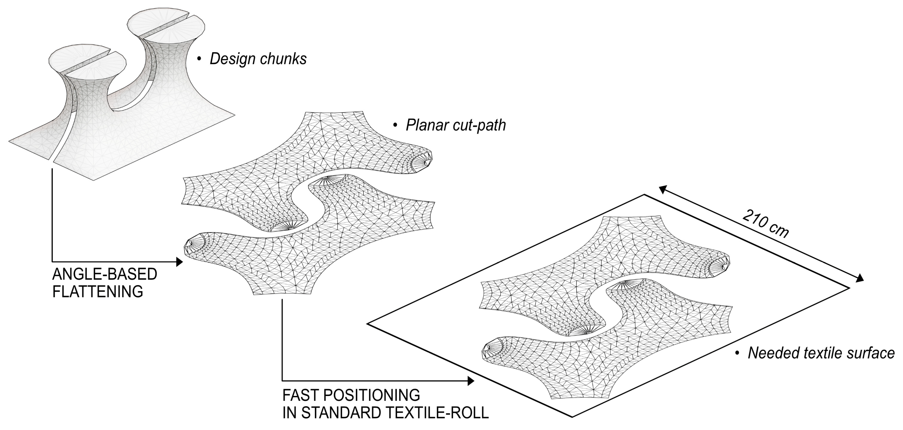
As previously mentioned, CTC is a production technology that leverages morphing membrane principles (
Figure 5), signifying a surface-based modelling approach, in contrast to the volume-based methodologies employed by CNC and FDM 3D-printing technologies. For this reason, the concept of infill percentage, a common metric in other manufacturing technologies, does not apply to CTC in the same way.
An iterative algorithm able to rapidly produce different design alternatives of viable shapes to be produced with the CTC technology was developed for the purpose.
Each BBOX volume resulting from the permutation of the different base dimensions and the respective z-height measures have been implemented within an optimization function set with the goal to produce a valid CTC design with the highest value of textile consumption based on the final mesh area. This parameter enables the identification of the maximum material consumption for each BBOX permutation.
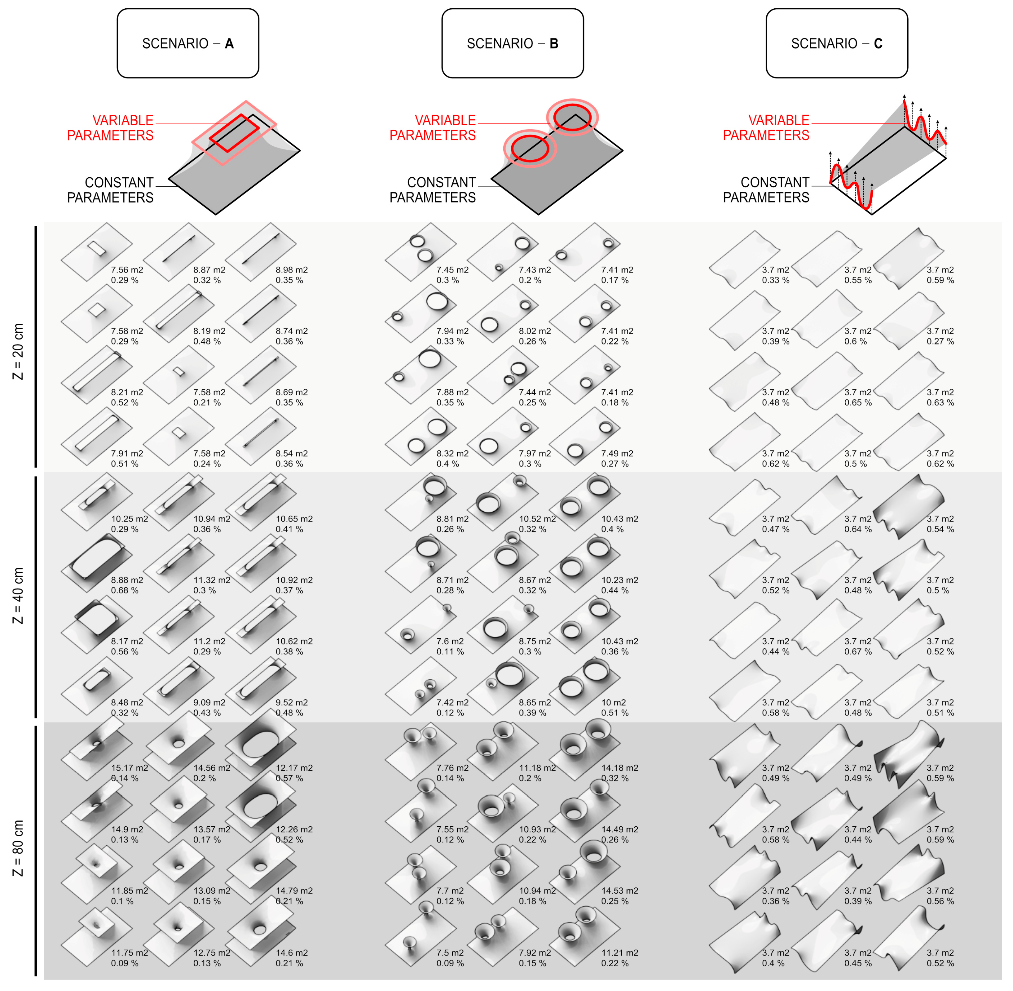
Furthermore, considering that CTC can be utilized to create various design geometries, three main configurations were selected to be developed into the optimization process. Each of these design geometries, henceforth referred to as “scenarios”, was chosen due to its particular representation of the design capabilities inherent in the CTC process.
The three scenarios (
Figure 6) can be essentially derived from the main design topologies which can be achieved by maximizing the use of the BBOX volume. Each scenario is built as a loft surface using inputs from different sketch profiles [
43].
Scenario 1 uses the base at the bottom of the BBOX as a fixed sketch profile, while the top of the BBOX can vary following an internal offset.
Scenario 2 uses the base at the bottom of the BBOX as a fixed sketch profile, while the top side of the BBOX is used to place two circular frames which may vary in radius and positioning.
Scenario 3 creates two different sketch profile on the shorter vertical sides of the BBOX. Each profile is generated as a spline interpolating six points which can individually vary in positioning.
After a loft surface is established on the generated frames, it is then converted into a polygonal mesh with a triangular base to be finally optimized as a minimal surface via a simulation workflow scripted via Kangaroo [
44].
Each iteration of the optimization algorithm served not only to produce the instance with the widest textile area but also a large number of intermediate steps. The resulting models were further categorized based on two additional variables: the equivalent infill percentage (calculated as the ratio between the underlying volume and the overall volume of the BBOX) and the actual textile consumption. The latter was determined by flattening each design onto a standard textile roll measuring 210 cm in width.
The data obtained from the analysis allowed us to quantify a range of material consumption for each scenario, detailing the follwoing: the minimal textile consumption; the maximum textile consumption; the average textile consumption; the average wood consumption for the frame production. Additionally, data regarding the equivalent infill volume allowed us to clusterize and map the results into an adequate system for the comparative analysis with the other selected technologies.
Based on the quantities obtained by applying the previous methodology,
Table 4 describes all the assumptions used for the LCA analysis.
4. Results
A total of 180 cases were analysed to screen the five defined steps of area (BASE and Steps 00–03) for each of the production processes to produce a unitized complex surface (combination of BBOX height and percentage of filling). The most relevant results have been included in the following discussion, and for a more complete view of the values obtained, summary tables of each area step are shown in the annexe.
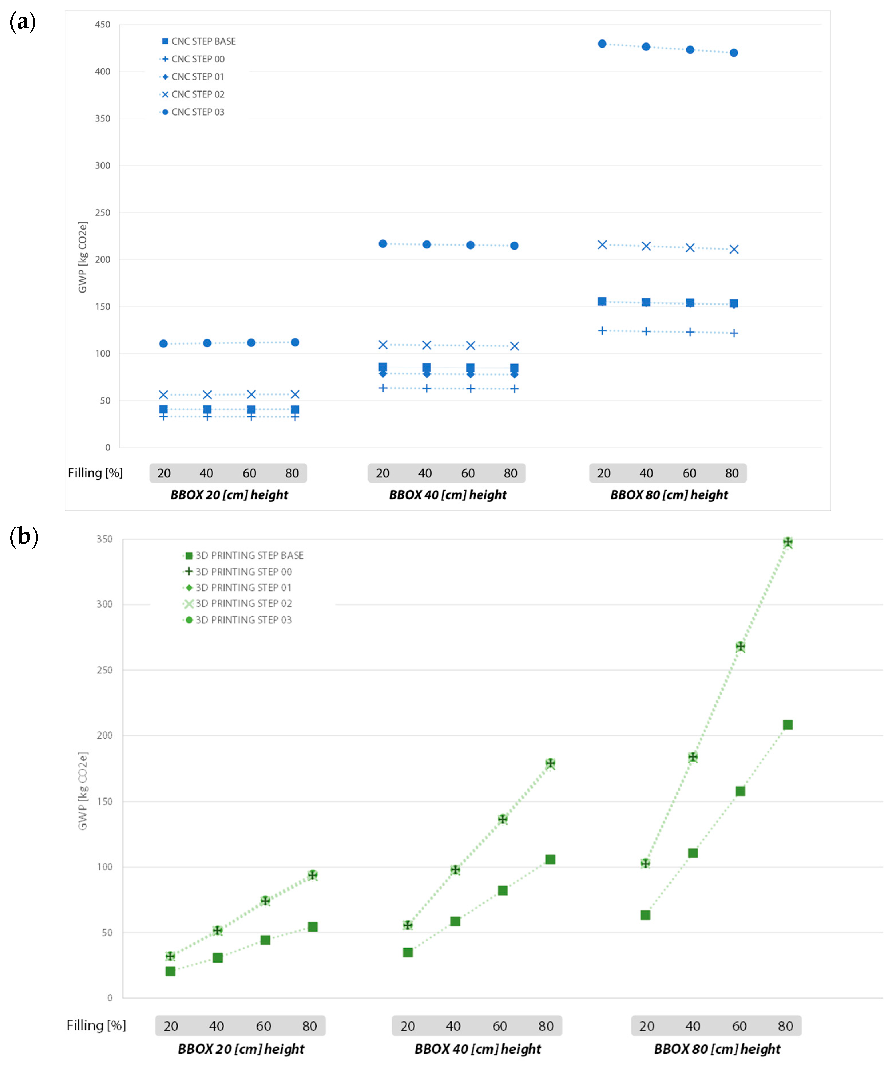
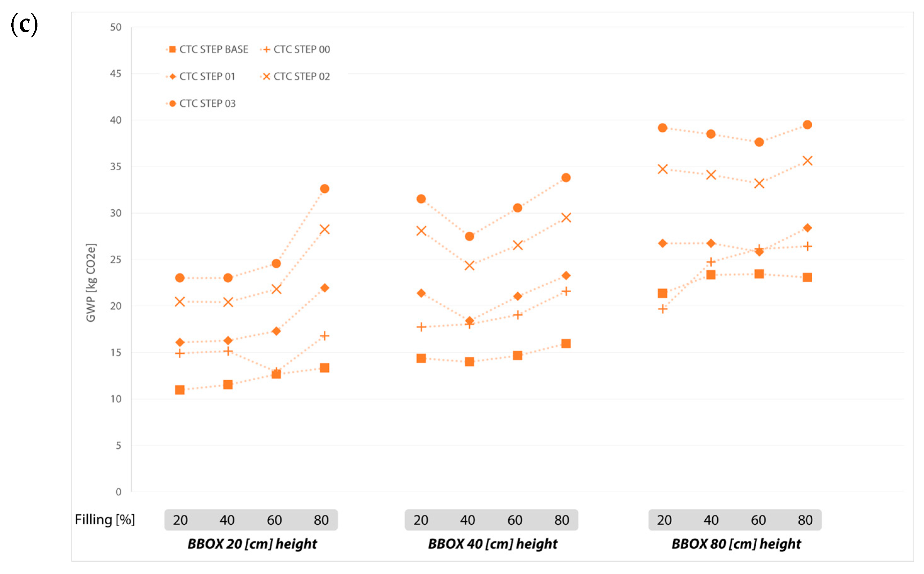
Initially, GWPs for each production process were analysed to understand the potential variations driven by the resultant percentage of filling and BBOX height of the desired unitized complex shape. Such progressions and differences have been documented in
Figure 7. As expected, the higher the step of the area and BBOX height, the higher the GWPs, as more material and machine use is foreseen. Nevertheless, the significant difference at extremes found in GWPs was surprisingly high (approximately x10 between CNC milling and CTC).
Moreover, each technology displayed a relatively different GWP increase rate due to steps of area and BBOX height variations, and a completely different trend at the same BBOX height with different percentages of filling. That is, for CNC milling, under the same BBOX height and step of area, the percentage of filling did not generate any relevant GWP variations, while a change on BBOX generated a ×2 GWP (
Figure 7a). Thus, one could conclude that for CNC milling processes the embodied carbon of a complex surface is further driven by the offset in height (i.e.,
z-axis) of the complex surface, rather than its projected area, and is independent of the percentage of filling of its BBOX. On the other hand, although 3D printing’s GWPs resulted similarly impacted by the offset in height of the complex surface compared to CNC milling (~×2 change with BBOX increase), the impact of the percentage of filling under the same step of the area and BBOX height is much more relevant (
Figure 7b). This becomes even more significant at a higher BBOX and larger step of area (~×3.5 from 20 to 80% of filling at BBOX 80). This can be related to the fact that with CNC milling the amount of raw material needed for a 20–80% percentage of filling is the same, while 3D printing augments proportionally with the percentage of filling (linked to the inherent characteristics of additive manufacturing processes).
On the other hand, CTC reported fewer variations in GWPs due to steps of area, percentage of filling and BBOX height. In fact, by altering only one of the domains, changes on GWPs are approximately ×1.5 or less. This can be attributed to the fact that, with CTC, the raw material required for producing the complex surface is like the total amount of an equivalent surface area in a plane. Also, CTC supports to reach the offset in height of the complex shape are less dense. Thus, CTC has a much lower raw material use than CNC milling and 3D printing and less machine time. Therefore, one could conclude that a complex surface manufactured with a CTC process is more likely to have lower embodied carbon, regardless of the complexity of its shape, compared to the CNC milling and 3D printing processes.
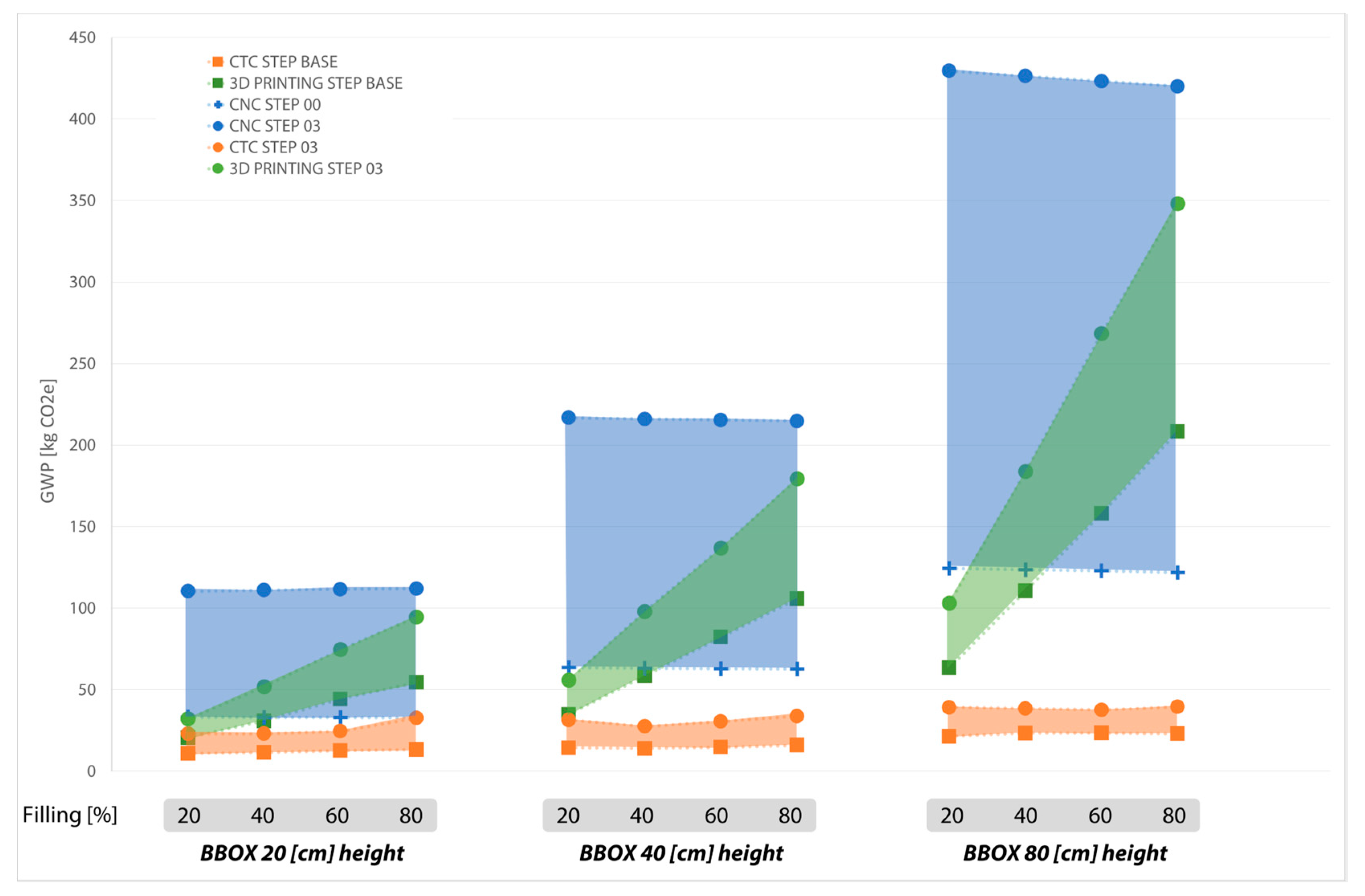
To make the comparison more direct, the results were grouped in
Figure 8 to help designers, architects, and manufacturers to select the most sustainable process in accordance with the type of complex surface that they hope to realize. The areas were drawn to represent the existence of the intervals of the different processes at more granular steps of each area, defined by taking the resulting highest and lowest GWPs.
For example, considering a BBOX 20 and a percentage of filling of 40 percent, it is evident that, for any base size (step of area), the least impactful process is CTC. Also, it is likely that only at a BBOX 20 and 20% filling a process like 3D printing could be more sustainable than CTC.
In brief, CNC milling has a higher embodied carbon than the other two processes. Nonetheless, all processes have a higher GWP at a higher raw material use (translated into steps of area), but the rate at which GWPs grow depends highly on the manufacturing process. Moreover, a linear behaviour can be established between GWPs and either BBOX or the percentage of filling. While CNC milling and 3D printing have a similar relationship with BBOX height, CTC has a slowing growth rate. Also, 3D printing has a steep growth in GWP due to the percentage of filling.
The trend in CNC milling is attributed to the fact that the quantity purchased is the same for each case and what changes are only the scraps which, however, affect the calculated GWP value by a minimum percentage. Thus, by increasing the height of the modules (BBOX height), the required volume of EPS increases, and the line will consequently always be flat but will stabilize on higher values. A peculiarity highlighted is that in the case in which the base area increases to 1.60 m × 0.90 m the amount of GWP is reduced. This phenomenon can be explained by taking into consideration the quantity of EPS needed the latter is equal to that of the previous step, but the waste is reduced, lowering the carbon emissions. For the subsequent steps, however, the value always increases, given that the number of modules is always greater.
On the contrary, in the 3D printing process, the filling percentage growth slope is more critical as its inherent characteristics of an additive manufacturing process require a denser internal structure on the volumes that represent the filled percentage of the bounding box while maintaining the same material at the base (similarly to CNC milling).
The CTC process, on the other hand, turns out to be less regular; the values for different filling percentages at a constant height are very similar to each other. But, if the height varies, then the value of emitted CO2 increases. Although this is not at the same rate as the other two production processes.
Finally, utilizing the proposed methodology of normalizing complex surfaces for a better comparison and by looking at the selected areas of the three analysed processes (
Figure 8), it is possible to note that, in any case, it is convenient to use the CTC process. This is mainly because this type of process uses much less material than the previous ones.
5. Limitations
The results obtained in this work have been produced for the realization of a double curvature complex surface under specific geometrical variation domains. Therefore, the results that another complex surface could have could deviate from what has been presented. Nevertheless, the authors expect that the normalization of BBOX height and percentage of filling will permit a comparison with any other complex surface construction.
Additionally, a further potential limitation is related to the scale of the analysis conducted. In fact, in the analyses carried out, we focused on a ‘single piece’ or ‘small-scale’ production rather than mass production. This decision, linked to the relevant market (custom product), can lead to an overestimation of input data (materials and energy) in certain configurations. However, it should be emphasized that the selected processes are inherently linked to the production scale, and any change in scale will require a re-evaluation of whether additional processes can be reconsidered.
6. Conclusions
Building design evolution includes the materialization of complex geometries and surfaces that are visually stunning, optimized for specific performances and/or customized for user’s preferences. This shift necessitated a move away from standardized systems and components to single-use, customized, and optimized solutions. A shift has been successfully achieved in design with computational tools for modelling, while efficient and sustainable manufacturing methods have been left behind.
Production methods such as CNC milling and 3D printing have been identified and widely used to respond to the abovementioned shift. Nevertheless, their carbon-saving potential is questionable due to the raw material use, type, and quantity, and the energy needed for their production.
The proposed method was proven to allow a normalized embodied carbon comparison (in terms of GWP) of the processing methods for the realization of a complex surface translated into steps of BBOX base area, BBOX height, and percentage of filling of the given BBOX. Moreover, such a process allowed us to test the carbon saving of CTC, which arises as an alternative for complex surfaces of a certain scale, with approximately 1/10th of the carbon footprint for their production.
Finally, the work presented provides an easy-to-use guideline for the selection of a production method for a complex surface that would render the manufacturing methods of complex building design shapes greener. In fact, the proposed work allows designers and architects to identify—accounting for different volumes of relevance—which process can improve the impact of their proposed solution. In addition, the utilized methodology and normalization could ease the comparison of the panel’s production cost and durability by establishing a more accurate functional unit.
Future works are foreseen to complement the elaborated database with intermediate, smaller, and bigger iterations of the tested complex surfaces. Additionally, such databases will become enriched with information on the potential costs of the studied manufacturing processes.
Author Contributions
Conceptualization, A.S., M.C., A.G.M., V.C., S.B., J.D.B.C. and T.P.; methodology A.S., M.C., A.G.M., V.C., S.B. and J.D.B.C.; validation, A.S., M.C., A.G.M., F.P. and T.P.; formal analysis, A.S., M.C., A.G.M., V.C., S.B., J.D.B.C., F.P. and T.P.; investigation, A.S., M.C., A.G.M., V.C. and S.B.; data curation, A.S., M.C., A.G.M., V.C. and S.B.; writing—original draft preparation, A.S., M.C., A.G.M., V.C., S.B. and J.D.B.C.; writing—review and editing A.S., M.C., A.G.M., J.D.B.C., F.P. and T.P.; visualization, A.S., M.C., A.G.M., V.C. and S.B.; supervision, A.S., A.G.M. and T.P.; project administration, A.S., A.G.M. and T.P. All authors have read and agreed to the published version of the manuscript.
Funding
This study was carried out within the MICS (Made in Italy—Circular and Sustainable) Extended Partnership and received funding from the European Union Next-GenerationEU (PIANO NAZIONALE DI RIPRESA E RESILIENZA (PNRR)—MISSIONE 4 COMPONENTE 2, INVESTIMENTO 1.3—D.D. 1551.11-10-2022, PE00000004) in the project STONE (Sustainable Ecodesign Reusing Quarrying Waste). This manuscript reflects only the authors’ views and opinions, neither the European Union nor the European Commission can be considered responsible for them.
Data Availability Statement
The data presented in this study are available on request from the corresponding author. The data are not publicly available due to a patent pending restriction.
Acknowledgments
This work has been made possible thanks to the support provided by SEEDLab@DABC (@Politecnico di Milano) for the technological and calculation aspects.
Conflicts of Interest
The authors declare no conflict of interest.
References
- Union, E. New European Bauhaus. Available online: https://new-european-bauhaus.europa.eu/index_en (accessed on 27 November 2023).
- Piroozfar, P.; Piller, F. (Eds.) Mass Customisation and Personalisation in Architecture and Construction; Routledge: England, UK, 2013. [Google Scholar] [CrossRef]
- The Next Production Revolution; OECD: Paris, France, 2017. [CrossRef]
- What Is the 3D Printing vs. Injection Moulding Cost-per-Unit Breakeven? Available online: https://www.xometry.com/resources/injection-molding/injection-molding-vs-3d-printing/ (accessed on 21 November 2023).
- Sigrid, B.-Ç. Computer Numeric Controlled Manufacturing for Freeform Surfaces in Architecture. In Emotion in Architecture, 1st ed.; Kuhlmann, D., Schinegger, K., Brell-Cokcan, S., Eds.; Luftschacht: Vienna, Austria, 2011; pp. 20–25. [Google Scholar]
- Roxas, C.L.; Bautista, C.R.; Dela Cruz, O.G.; Dela Cruz, R.L.; De Pedro, J.P.; Dungca, J.R.; Lejano, B.A.; Ongpeng, J.M. Design for Manufacturing and Assembly (DfMA) and Design for Deconstruction (DfD) in the Construction Industry: Challenges, Trends and Developments. Buildings 2023, 13, 1164. [Google Scholar] [CrossRef]
- Campbell, C. The Craft Consumer. J. Consum. Cult. 2005, 5, 23–42. [Google Scholar] [CrossRef]
- Gebler, M.; Uiterkamp, A.J.M.S.; Visser, C. A global sustainability perspective on 3D printing technologies. Energy Policy 2014, 74, 158–167. [Google Scholar] [CrossRef]
- Chen, D.; Heyer, S.; Ibbotson, S.; Salonitis, K.; Steingrímsson, J.G.; Thiede, S. Direct digital manufacturing: Definition, evolution, and sustainability implications. J. Clean Prod. 2015, 107, 615–625. [Google Scholar] [CrossRef]
- Agusti-Juan, I.; Habert, G. An environmental perspective on digital fabrication in architecture and construction. iving Systems and Micro-Utopias: Towards Continuous Designing. In Proceedings of the 21st International Conference on Computer-Aided Architectural Design Research in Asia (CAADRIA 2016), Melbourne, Australia, 30 March–2 April 2016; pp. 797–806. [Google Scholar] [CrossRef]
- Moore, G.E.; Agogino, A.M.; Goucher-Lambert, K. Towards Sustainable Life Cycles of Making in Small Scale Fabrication Spaces. Proc. Des. Soc. 2023, 3, 3611–3620. [Google Scholar] [CrossRef]
- Nations, U. Transforming Our World: The 2030 Agenda for Sustainable Development. Available online: https://sustainabledevelopment.un.org/post2015/transformingourworld/publication (accessed on 10 November 2023).
- Poli, T.; Mainini, A.G.; Speroni, A.; Zani, A. Elemento di Rivestimento Per L’impiego in Edilizia e Metodo Per la Sua Realizzazione, IT201900005300A1. 2019. Available online: https://patents.google.com/patent/IT201900005300A1/it?oq=IT201900005300A1 (accessed on 10 November 2023).
- Poli, T.; Mainini, A.G.; Speroni, A. Method for the Forming and Finishing of an Accessory Cladding Element for Use in Architecture and Design, EP3990720A1. 2020. Available online: https://patents.google.com/patent/EP3990720A1/en?oq=IT201900010485A1 (accessed on 10 November 2023).
- Poli, T.; Mainini, A.G.; Speroni, A. Metodo Per Realizzare la Formatura e la Finitura di Un Elemento di Rivestimento Accessorio Per L’impiego in Architettura e Design, IT201900010485A1. 2019. Available online: https://patents.google.com/patent/IT201900010485A1/en?oq=IT201900010485A1 (accessed on 10 November 2023).
- Arturo, T. AAD Algorithms-Aided Design from traditional drawings to the parametric diagram. In AAD Algorithms-Aided Design, 1st ed.; Le Penseur: Potenza, Italy, 2014. [Google Scholar]
- Schumacher, P. Parametricism: A New Global Style for Architecture and Urban Design. Archit. Des. 2009, 79, 14–23. [Google Scholar] [CrossRef]
- Almantas, S. Ideology as geometry: A note on parametricism and its theoretical foundations. Symmetry Cult. Sci. 2020, 31, 353–364. [Google Scholar] [CrossRef]
- Al-Azzawi, T.; Al-Majidi, Z. Parametric architecture: The second international style. IOP Conf. Ser. Mater. Sci. Eng. 2021, 1067, 012019. [Google Scholar] [CrossRef]
- Gawell, E. Non-euclidean geometry in the modelling of contemporary architectural forms. J. Pol. Soc. Geom. Eng. Graph. 2013, 24, 35–43. [Google Scholar]
- Elipe, M.D.Á.; Díaz, J.A. Review of contemporary architecture projects based on nature geometries. Rev. Construcción 2018, 17, 215–221. [Google Scholar] [CrossRef]
- Ostwald, M. Systems and Enablers: Modelling the Impact of Contemporary Computational Methods and Technologies on the Design Process. Comput. Des. Methods Technol. Appl. CAD CAM CAE Educ. 2012, 17. [Google Scholar] [CrossRef]
- Toromanoff, A. Curved: Bending Architecture. In G—Reference, Information and Interdisciplinary Subjects Series; Lannoo: Tielt, Belgium, 2021. [Google Scholar]
- Kim, K.; Son, K.; Kim, E.-D.; Kim, S. Current trends and future directions of free-form building technology. Arch. Sci. Rev. 2015, 58, 230–243. [Google Scholar] [CrossRef]
- Brookes, A.J.; Meijs, M. Cladding of Buildings, 4th ed.; Taylor & Francis: Abingdon, UK, 2008. [Google Scholar] [CrossRef]
- Souza, E. What Materials Can Be Used for Façade Cladding. Available online: https://www.archdaily.com/979639/what-materials-can-be-used-for-facade-cladding?ad_source=search&ad_medium=search_result_articles? (accessed on 29 June 2023).
- Marius, M.; Anastasiadis, A.; Kampouris, A. Are free form architecture ecological buildings. J. Environ. Prot. Ecol. 2014, 15, 366–373. [Google Scholar]
- Kavuma, A.; Ock, J.; Jang, H. Factors influencing Time and Cost Overruns on Freeform Construction Projects. KSCE J. Civ. Eng. 2019, 23, 1442–1450. [Google Scholar] [CrossRef]
- Hambleton, D.; Howes, C.; Hendricks, J.; Kooymans, J.; Yolles, H. Study of Panelization Techniques to Inform Freeform Architecture. Glass Perform. Days 2009, 245–249. [Google Scholar]
- Ock, J.-H. Testing as-Built Quality of Free-Form Panels: Lessons Learned from a Case Study and Mock-up Panel Tests. Appl. Sci. 2021, 11, 1439. [Google Scholar] [CrossRef]
- Moskaleva, A.; Safonov, A.; Hernández-Montes, E. Fibre-Reinforced Polymers in Freeform Structures: A Review. Buildings 2021, 11, 481. [Google Scholar] [CrossRef]
- Ock, J.H. Assessing the Suitability of the Cold Bending Method in Fabricating Free-form Façade Panels. Civ. Eng. Res. J. 2018, 5, 17–27. [Google Scholar] [CrossRef]
- Alonso-Pastor, L.; Lauret-Aguirregabiria, B.; Castañeda-Vergara, E.; Domínguez-García, D.; Ovando-Vacarezza, G. Free-Form Architectural Façade Panels: An Overview of Available Mass-Production Methods for Free-Form External Envelopes. In Construction and Building Research; Springer: Berlin/Heidelberg, Germany, 2014. [Google Scholar]
- Castañeda, E.; Lauret, B.; Lirola, J.M.; Ovando, G. Free-form architectural envelopes: Digital processes opportunities of industrial production at a reasonable price. J. Facade Des. Eng. 2015, 3, 1–13. [Google Scholar] [CrossRef]
- Han, D.; Yin, H.; Qu, M.; Zhu, J.; Wickes, A. Technical Analysis and Comparison of Formwork-Making Methods for Customized Prefabricated Buildings: 3D Printing and Conventional Methods. J. Archit. Eng. 2020, 26, 04020001. [Google Scholar] [CrossRef]
- Jipa, A.; Bernhard, M.; Dillenburger, B.; Ruffray, N.; Wangler, T.; Flatt, R. skelETHon Formwork 3D Printed Plastic Formwork for Load-Bearing Concrete Structures. In Blucher Design Proceedings; Editora Blucher: São Paulo, Brazil, 2017; pp. 345–352. [Google Scholar] [CrossRef]
- Jipa, A.; Bernhard, M.; Ruffray, N.; Wangler, T.; Flatt, R.; Dillenburger, B. Formwork fabrication freedom for a concrete canoe. Gestão Tecnol. Proj. 2019, 14, 25–44. [Google Scholar] [CrossRef]
- Faludi, J.; Bayley, C.; Bhogal, S.; Iribarne, M. Comparing environmental impacts of additive manufacturing vs traditional machining via life-cycle assessment. Rapid Prototyp. J. 2015, 21, 14–33. [Google Scholar] [CrossRef]
- Wu, Z.; Memari, A.; Duarte, J. State of the Art Review of Reinforcement Strategies and Technologies for 3D Printing of Concrete. Energies 2022, 15, 360. [Google Scholar] [CrossRef]
- BS EN ISO 14067; Greenhouse Gases—Carbon Footprint of Products—Requirements and Guidelines for Quantification. British Standards Institution: London, UK, 2018.
- BS EN 15804; Sustainability of Construction Works—Environmental Product Declarations—Core Rules for the Product Category of Construction Products. British Standards Institution: London, UK, 2014.
- Intergovernmental Panel on Climate Change (IPCC). Climate Change 2013—The Physical Science Basis: Working Group I Contribution to the Fifth Assessment Report of the Intergovernmental Panel on Climate Change; Cambridge University Press: Cambridge, UK, 2014. [Google Scholar] [CrossRef]
- Chang, K.-H. e-Design. Computer-Aided Engineering Design; Academic Press: New York, NY, USA, 2015. [Google Scholar] [CrossRef]
- Kangaroo 2. Available online: https://grasshopperdocs.com/addons/kangaroo-2.html (accessed on 3 April 2023).
| Disclaimer/Publisher’s Note: The statements, opinions and data contained in all publications are solely those of the individual author(s) and contributor(s) and not of MDPI and/or the editor(s). MDPI and/or the editor(s) disclaim responsibility for any injury to people or property resulting from any ideas, methods, instructions or products referred to in the content. |
© 2023 by the authors. Licensee MDPI, Basel, Switzerland. This article is an open access article distributed under the terms and conditions of the Creative Commons Attribution (CC BY) license (https://creativecommons.org/licenses/by/4.0/).


 ,
, 


