Article

Mechanical Properties and Microscopic Mechanism of Basic Oxygen Furnace (BOF) Slag-Treated Clay Subgrades

Department of Civil and Environmental Engineering, Nazarbayev University, Astana 010000, Kazakhstan
*
Author to whom correspondence should be addressed.
Buildings 2023, 13(12), 2962; https://doi.org/10.3390/buildings13122962
Submission received: 14 October 2023 / Revised: 7 November 2023 / Accepted: 13 November 2023 / Published: 28 November 2023
(This article belongs to the Special Issue Materials Engineering in Sustainable Buildings)

Abstract

:
Civil engineering faces a substantial challenge when dealing with soft and compressible clayey soils. Conventional soil stabilization techniques involving ordinary Portland cement (OPC) result in notable CO2 emissions. This study explores the utilization of basic oxygen furnace (BOF) slag, a by-product of steel production, for strengthening kaolin clay. This research investigates the influence of BOF slag particle size, BOF slag content, and the use of activators such as lime and ground granulated blast-furnace slag (GGBFS) on the stabilization of kaolin clay. The strength development is assessed through unconfined compressive strength (UCS) test, bender element (BE) test, and scanning electron microscopy (SEM). The findings reveal that higher BOF content and extended curing periods enhance soil strength, and lime and GGBFS effectively augment the stabilizing properties of BOF slag. Stabilizing kaolin clay with a 30% BOF/GGBFS mixture in a 50/50 ratio with 1% lime and curing for 7 days yielded a compressive strength of 753 kPa, meeting the Federal Highway Administration’s requirement for lime-treated soil. These combined measures contribute to developing a more robust and stable material with enhanced geotechnical properties.

1. Introduction

Soil stabilization plays a crucial role in geotechnical engineering, which aims to improve the mechanical properties of soil for various construction applications. One of the most effective ways to achieve stabilization is using chemical stabilization, which is the process of introducing chemical agents into soils to modify their physical and chemical characteristics [1,2,3,4]. Chemical stabilizers can be divided into three groups: traditional, non-traditional, and by-product stabilizers [3]. Traditional calcium-based stabilizers such as lime and ordinary Portland cement (OPC) are commonly used due to their strong bonding properties. However, there is a growing interest in environmentally friendly alternatives for soil stabilization. An example of an alternative option is calcium sulfoaluminate (CSA) cement, a non-traditional stabilizer that possesses environmentally beneficial characteristics while also retaining effective soil stabilization capabilities [5,6,7,8,9]. Also, byproduct stabilizers, such as rice husk ash and lignin, are considered cost-effective and environmentally friendly substitutes for traditional and non-traditional stabilizers in various civil engineering applications [10,11,12,13]. In a recent study, the life cycle assessment (LCA) tool was employed to evaluate the environmental impact of lignin and lime. This assessment revealed that lignin has a significantly lower contribution to global warming potential (GWP) than lime [11].
Several researchers have explored using steel waste materials as cost-effective and readily available alternatives for soil stabilization [14,15,16]. Using steel slag in soil stabilization not only enhances the soil’s properties but also effectively addresses waste disposal concerns, thus aligning with the goal of promoting sustainable and environmentally friendly approaches to soil stabilization. One instance involves the generation of significant quantities of basic oxygen furnace (BOF) slag, a by-product resulting from steel production. The accumulation of BOF slag in the field can give rise to environmental concerns and economic challenges [17,18]. However, BOF slag can serve as an eco-friendly alternative to OPC, as its production requires less energy and results in lower C O 2 emissions [18,19]. BOF slag has a similar mineralogical composition to OPC, with the main difference being the presence of slowly hydrating dicalcium silicate ( C 2 S ) in BOF slag and faster hydrating tricalcium silicate ( C 3 S ) in OPC [15,19]. This means that soil stabilization using BOF slag could result in slower strength gain than OPC [15,16,20,21,22].
While BOF slag alone has shown promise as a soil stabilizer, its effectiveness can be further enhanced by combining it with a calcium-based material (e.g., lime) and another iron industry waste (pozzolan) material (e.g., ground granulated blast-furnace slag (GGBFS) [14,15,16]. For example, BOF slag has demonstrated superior strength and activity compared to GGBFS slag when stabilizing dispersed clay, although a higher percentage of GGBFS (20–25%) is recommended to counteract clay dispersity [21]. The mechanisms behind the strength improvement of BOF-stabilized soil involve processes such as C 2 S hydration (similar to Portland cement), the presence of free lime, and the pozzolanic reaction between C a ( O H ) 2 and Si/Al in clay [22,23].
Cikmit and Tsuchida [23] examined the effect of different particle sizes on strength improvement in marine clay soil samples stabilized with BOF slag. It was observed that BOF slag particles with a maximum size of 37.5 mm remained inactive over 10 h, whereas those with a maximum size of 9.5 mm showed a noticeable decrease in inactivity. In addition, particles larger than 9.5 mm act as aggregates, whereas those smaller than 9.5 mm function as cement between solid particles. Additionally, soil texture is closely linked with the soil particle composition, leading to disparities in the dimensions and arrangement of soil pores. Such discrepancies in pore size and distribution directly impact the soil’s hydraulic conductivity and water potential [24]. Thus, it was concluded that finer BOF slag particles with longer curing periods enhance strength more than coarser particles. However, the primary effect of the BOF slag and its synergistic effect with lime and GGBFS on stabilizing kaolin clay, considering the effect of various particle sizes, have not been investigated yet.
This research explores the primary effect of BOF slag and the synergistic effect of incorporating lime and GGBFS alongside BOF slag to activate soil bonding and enhance soil stabilization. The effect of particle size, BOF content, and activators such as lime and GGBFS on the stabilization process’s effectiveness is considered. The stabilization process is assessed by unconfined compressive strength (UCS) and bender element (BE) tests, and scanning electron microscopy (SEM) observation to gain a better understanding of the underlying mechanisms.

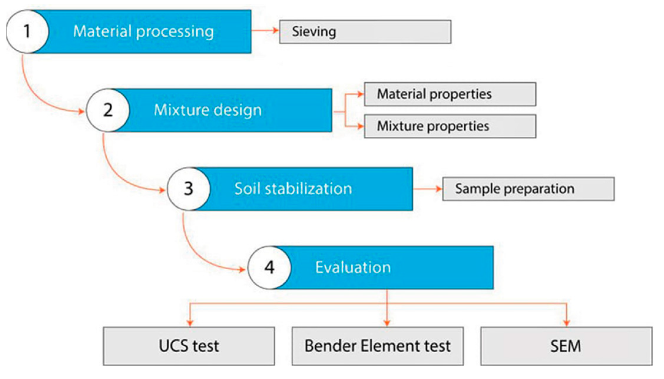
2. Experimental Procedure
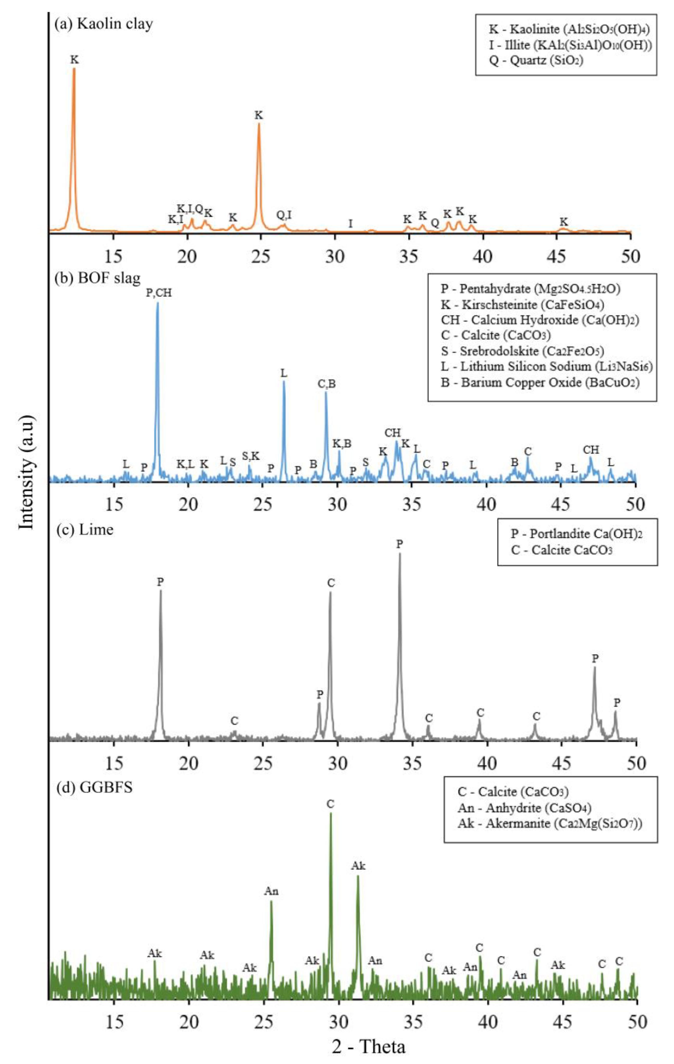
The experimental procedure was composed of four parts. The first part involved processing materials, where BOF slag was sieved to obtain different particle sizes. The second step was mixture design, in which both material and mixture properties were taken into account to obtain an optimal combination of solids and water. Next, samples were prepared with 50 × 100 mm cylindrical steel molds. Finally, the last part involved the evaluation of the specimens using UCS, BE tests, and SEM. A diagram of the experimental program is shown in Figure 1.

2.1. Materials

In this study, kaolin clay and BOF slag were used as the primary binder, lime, and GGBFS as the activator (Figure 2). According to the USCS, kaolin clay is classified as MH (silt with high plasticity). The fresh BOF slag was obtained from a steel company near Karaganda region in Kazakhstan. The basic properties of kaolin clay and BOF slag are provided in Table 1.
The particle size distribution of kaolin clay was analyzed using the QICPIC particle size and shape analyzer equipment with an M7 lens, which has a measurement range of 4.2–8665 µm. The gradation of BOF slag was conducted according to ASTM C136 [31]. The particle size distribution for both kaolin clay and BOF slag is shown in Figure 3. We used seven different particle sizes of BOF slag, as illustrated in Figure 4. To investigate the effect of different particle sizes on the stabilization process of the kaolin clay, four diverse categories of BOF slag (BOF A (4.75–0.075 mm), BOF B (1.18–0.075 mm), BOF C (0.3–0.075 mm), and BOF D (<0.075 mm)) were used by gradually excluding the maximum fine aggregate sizes. The mineralogical properties of the soil, BOF slag, lime, and GGBFS used in this study were acquired using X-ray diffraction (XRD) analysis (Figure 5). The chemical composition of the materials was obtained through X-ray fluorescence (XRF) analysis (Table 2).

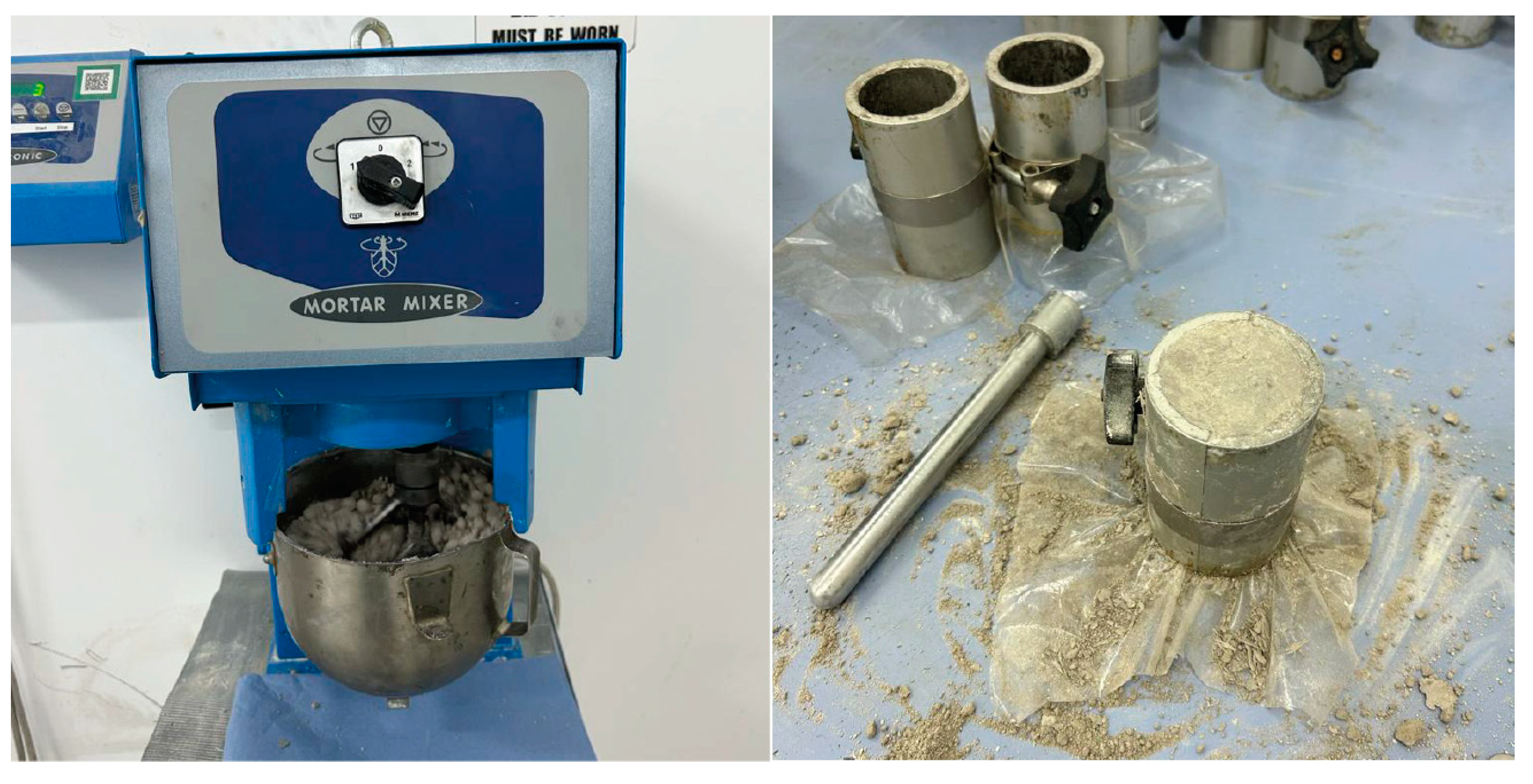
2.2. Mixture Design and Sample Preparation

The mixture design is presented in Table 3. The initial phase of the study focused on investigating the impact of particle size variation in BOF slag on soil stabilization. The mixture design comprised 30% BOF slag, representing the maximum percentage used in this study. Four categories were incorporated according to different particle sizes of BOF slag: BOF A (4.75–0.075 mm), BOF B (1.18–0.075 mm), BOF C (0.3–0.075 mm), and BOF D (<0.075 mm). Curing periods of 3, 7, 14, and 28 days were employed. Subsequently, the effect of different BOF slag contents (10%, 20%, and 30% of BOF D) was examined, with curing durations extended to 112 days. The extended curing period is essential for fine BOF particles, as they undergo a hydration reaction similar to cement, forming cementation compounds. Furthermore, activators such as lime and GGBFS were introduced to the soil–BOF mixture to assess their effectiveness in stabilizing clay. The mixtures were cured for up to 112 days. Lime was added at 1%, 3%, and 5% ratios from the soil mass, and the samples were evaluated for UCS and shear-wave velocity ( V s ) over a 112-day period. The 1% lime addition yielding the highest test results up to 28 days was selected as a fixed parameter for the subsequent stages of the study. Finally, the influence of GGBFS was investigated by substituting 25% and 50% of the BOF slag content. The aim was the evaluation of the impact of GGBFS on the overall performance of the mixture.
The samples were prepared in steel cylindrical molds (50 × 100 mm) with predetermined optimum moisture content (OMC) from the standard proctor test (ASTM D698 [28]). The binder ratio was determined based on the mass of dry soil, and water content on the mass of total solids. All the ingredients were dried before use and mixed in the mortar mixer. The samples were prepared with manual compaction of 3 layers with 25 blows (Figure 6). The height and diameter of the samples were measured after extrusion, and they were wrapped into polyethylene with rubber bands to avoid moisture loss. Finally, the samples were cured at room temperature during the curing period (Table 3).

2.3. Testing Methods

The mechanical properties of the stabilized soil were determined using UCS and BE tests (Figure 7). UCS refers to the maximum axial compressive stress that a cylindrical soil specimen can withstand before it fails. It is mainly used to evaluate the soil’s load-bearing capacity because it is a quick and cost-effective testing method. The UCS test was performed according to ASTM D2166 [32], with a constant loading rate of 1 mm/min (Figure 7a).
To determine the V s of the sample, a BE test was carried out in accordance with ASTM D8295 [33]. This test involves placing two piezoelectric materials on the top and bottom of the soil sample (Figure 7b) and inputting the sample height into the GDS Bender Element v 2.2.13 software. The V s parameter is determined according to Equation (1), by analyzing the wave travel time through the specimen length, from the top source to the bottom receiver, using the first-arrival method (Figure 8). In the first arrival method, the travel time is defined as the time between the beginning of the transmitted and received signals, and it can also be called the start-to-start method. The first arrival of shear-wave propagation was determined by selecting the point where the zero value was obtained following the first bump. Figure 8 clearly shows a near-field effect at low frequencies (2–15 kHz). It was observed that using higher frequencies could lead to a reduction in the near-field effect in stiffer samples. Therefore, using this approach, the BE test results were analyzed to obtain V s .
V s = L t
A scanning electron microscopy (SEM) analysis was used to examine the microscopic structure of the stabilized kaolin clay. The test involves directing a high-energy electron beam onto the surface of a specimen, which causes the release of secondary electrons detected with a sensor. The resulting signal creates a highly magnified image of the specimen’s surface. Before this test, the stabilized soil powder was glued to a holder and coated with 10 nm gold to improve the quality of the results. The SEM test was conducted using Zeiss Crossbeam 540 equipment. All micrographs were taken with magnification capacities of 5000 and 10,000.

3. Results

3.1. OMC–MDD of Mixtures

Figure 9a reveals a distinct relationship between the optimum moisture content (OMC) and the maximum dry density (MDD), demonstrating that an increase in BOF particles corresponds to an increase in OMC and a simultaneous reduction in MDD. In terms of analyzing variable BOF slag contents, Figure 9b illustrates a clear positive correlation between OMC and MDD and the increasing concentrations of BOF; in other words, as BOF content increases, both OMC and MDD increase. The increased MDD is attributable to the higher specific gravity of the coarser particles, while the rise in OMC is linked to the increased water absorption resulting from the incorporation of BOF slag. However, it is important to note that the differences in the OMC–MDD relationships for BOF content levels of 10%, 20%, and 30% are relatively modest. As shown in Figure 9c, adding lime results in a notable increase in OMC and a corresponding decrease in MDD. This phenomenon can be attributed to the increased water demand required to facilitate the pozzolanic soil–lime reactions involving calcium hydroxide (Ca(OH)₂). Conversely, Figure 9d demonstrates that incorporating GGBFS leads to a decrease in OMC and a concurrent increase in MDD. This trend is linked with the capability of GGBFS to enhance the compaction of the mixture with reduced water content, and the subsequent increase in MDD can be attributed to the high specific gravity of the mixture.

3.2. The Effect of BOF Particle Size

Figure 10 presents the results of BE and UCS tests for various particle sizes of the BOF slag used to stabilize kaolin clay over different curing durations (3, 7, 14, and 28 days). In the early stages of curing (3 and 7 days), both the UCS and shear-wave velocity ( V s ) exhibited fluctuations and did not show a significant increase in UCS and V s . This indicates that a 3-to-7-day curing period is insufficient for achieving substantial soil stabilization using various particle sizes of the BOF slag. Figure 10a shows that the stiffness of the stabilized soil reaches its maximum value when using BOF slag with a particle size greater than 0.075 mm (BOF D). This implies that the stiffness of the stabilized soil is affected by the particle size of the BOF slag. Figure 10b exhibits a noticeable trend according to which the UCS values increase as the particle size of the BOF slag decreases. This indicates that finer particles result in more substantial soil stabilization.
Additionally, both UCS and V s results exhibit an increasing trend with longer curing times, indicating that longer curing enhances the stiffness and strength of the soil sample. Notably, the most significant improvement in UCS for BOF D is observed between the 3-day and 28-day curing periods, with a substantial increase of 215 kPa. Similarly, the V s value shows an improvement of 119 m/s. These results highlight a positive correlation between the curing time, the stiffness of the soil sample, and its strength. Furthermore, the influence of particle size, particularly the highest values of UCS and V s , demonstrates that BOF D with a particle size less than 0.075 mm significantly affects soil stabilization. This can be attributed to the utilization of finer particles of the BOF slag, which results in a larger surface area contact between the soil skeleton and free lime, leading to a more efficient soil stabilization process than coarser particles.
Figure 11 illustrates the stress–strain behavior of different particle sizes during the 28-day curing period. The samples demonstrated increased strength with longer curing periods. Prolonged plastic deformation was predominantly observed in BOF A and BOF B throughout all curing periods, while it was primarily noticeable in BOF C and BOF D during the early curing stages. As the curing period reached 14 and 28 days, BOF C and BOF D showed brittle behavior, indicating the development of cementitious bonds within the samples. Notably, the fine BOF particles had the highest UCS values and displayed brittle behavior, as shown in the stress–strain curve. The inclusion of fine BOF slag in the mixture effectively reduced the plasticity of kaolin clay, contributing to improved performance and stability.

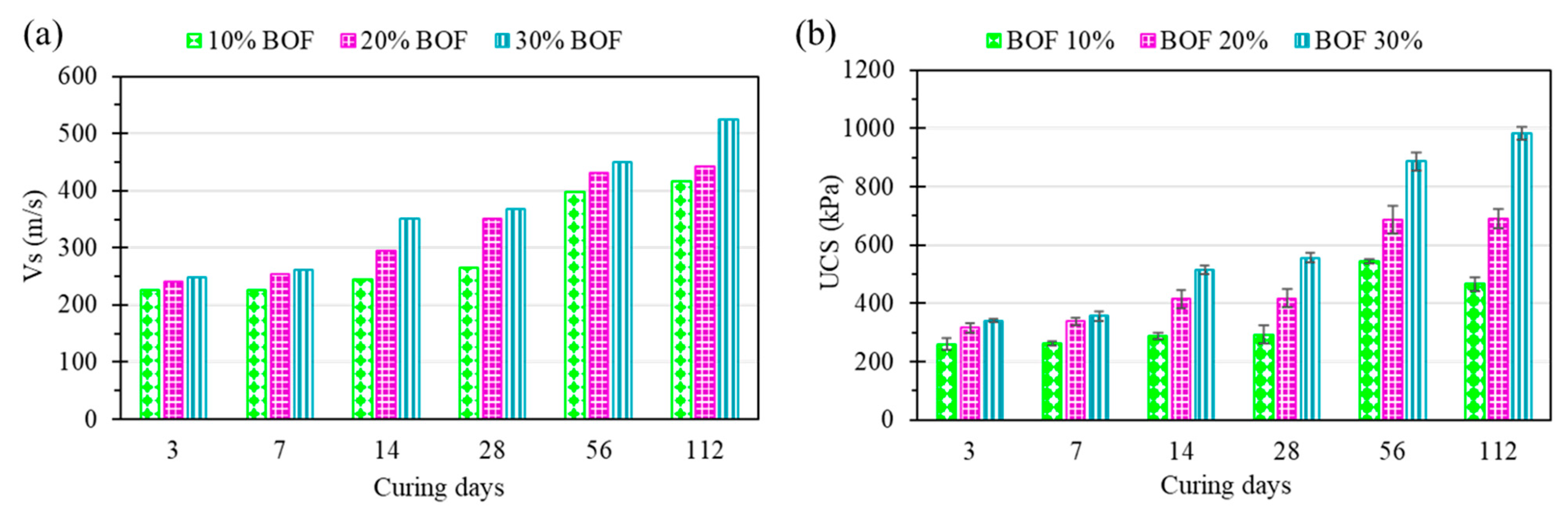
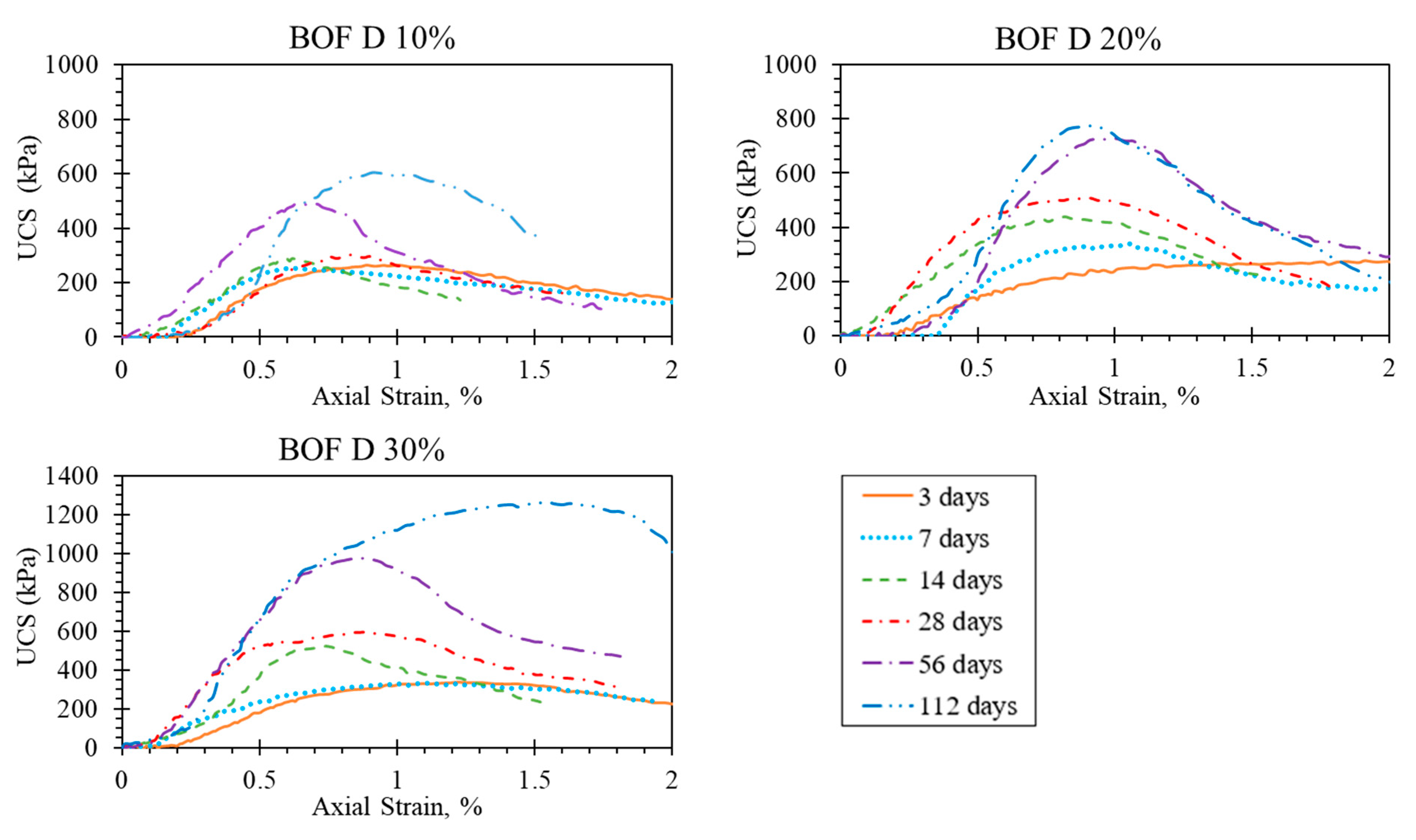
3.3. The Effect of BOF Slag Content

After identifying BOF D as the optimal particle size, the next step involved examining the impact of different percentages (10%, 20%, and 30%) of the BOF slag on the UCS and V s of the stabilized soil. Figure 12 illustrates the results of the (a) BE and (b) UCS tests conducted on BOF D samples over a curing period ranging from 3 to 112 days. Consistently, the highest UCS and V s values were observed when 30% BOF slag was added throughout the entire curing period. The results also exhibited a consistent pattern of improvement across all three percentage variations, with BD10 displaying the lowest values and BD20 demonstrating intermediate values. Additionally, BD10 showed limited activity during the 28-day curing period compared to BD20 and BD30. The differences between the results at 3 and 7 days were minimal, indicating insignificant improvements. However, a substantial increase in UCS and V s was observed after a 28-day curing period, emphasizing the significance of the curing duration in enhancing the properties of the clay stabilized with the BOF slag. These findings establish a direct relationship among the BOF slag content, the curing period, and the UCS and V s of the BOF slag-stabilized soil. Figure 13 illustrates the stress–strain relationship for the stabilized soil with 10%, 20%, and 30% BOF D. It can be observed that prolonged plastic deformation is more prominent during the early stages of curing, specifically on days 3 and 7. However, starting from the 14th day of curing, a transition to brittle behavior becomes evident, indicating the occurrence of the hydration reaction within the sample. It is noteworthy that the initial increase in strength during the early curing phases can be attributed to the presence of free lime in the BOF slag. When in contact with water, the free lime undergoes hydration, leading to a pozzolanic reaction over an extended period. This process contributes to enhancing the stabilized soil’s properties, with the development of hydration products and cementitious bonds playing a crucial role in improving the material’s overall performance. Therefore, the stress–strain relationship for different percentages of BOF D (10%, 20%, and 30%) provides valuable insights into the progression of soil stabilization with respect to the curing time and the percentage of fine BOF slag added to the mixture.

3.4. The Effect of Lime in BOF-Stabilized Soil

In the previous experiment, BOF D at a content of 30% was identified as the optimal dosage for soil stabilization based on the highest values obtained in the (a) BE and (2) UCS tests. The next step involved investigating the combination of BOF D with hydrated lime to determine the most effective lime percentage. Three different percentages of hydrated lime (1%, 3%, and 5%) were used as activators for the BOF slag, and the samples were cured for up to 112 days to evaluate the impact of lime on the stabilization process. Figure 14 illustrates the results of the BE and UCS tests for the samples with BOF D and different lime percentages (BD30L1, BD30L3, and BD30L5) over the curing period of 3 to 112 days. Interestingly, the results indicate that the 1% lime addition rate yielded the highest UCS and V s values for the 28-day curing period. However, beyond 28 days, a reversed trend was observed, with the predominance of the 5% lime addition rate in both tests. This can be attributed to the higher concentration of calcium oxide in the larger quantity of lime, which begins to activate and contributes to the stabilization process after 28 days. The addition of 5% lime significantly increased the maximum strength to approximately 500 kPa after 112 days, along with a V s value of about 210 m/s, as compared to the previous experiment without lime. These findings underscore the significance of both the lime percentage and the curing time when activating the performance of BOF slag-stabilized soil. Furthermore, they suggest that a higher lime content may be more beneficial in the long run, as it allows for the better activation of the BOF slag over time.

3.5. The Effect of GGBFS on Lime-Activated BOF Slag-Stabilized Soil

In this study, the effect of GGBFS on lime-activated BOF slag-stabilized soil was explored as a partial replacement for the BOF slag at 25% and 50% rates. In this scenario, GGBFS replaced the 30% BOF slag in proportions of 25/75 and 50/50 with a fixed lime content of 1%. Figure 15 presents the results of the (a) BE and (b) UCS tests for BD30L1G25 and BD30L1G50 samples during curing period of 3 to 112 days. Based on the findings, the 50% GGBFS replacement exhibited higher UCS and V s values than the 25% replacement in all curing dayss. The UCS and V s values continued to increase over time, exhibiting the highest values compared to previous experiments in which the BOF slag was used without any additives and in combination with lime. These results highlight the potential advantages of incorporating GGBFS as a partial replacement for the BOF slag in soil stabilization. In addition, the improved performance achieved through utilizing GGBFS emphasizes its potential benefits in soil stabilization applications.

3.6. UCS and V s Correlation

Figure 16 shows the relationships between the UCS and V s values. Linear regressions were performed for each case, and the charts demonstrate positive correlations between all the parameters. The R-squared values obtained from the analysis of various factors, namely different particle sizes of the BOF slag (BA30, BB30, BC30, and BD30), different BOF slag concentrations (BD10, BD20, and BD30), different lime concentrations (1%, 3%, and 5%), and different GGBFS proportions (25% and 50%), were 0.86, 0.88, 0.96, and 0.96, respectively. These values surpass 0.8, indicating a strong correlation between the UCS and V s values, as well as a high level of predictive capability. It should be noted that the effect of different BOF slag particle sizes was observed for the 28-day curing period, whereas the remaining ones were tested for up to 112 days. These findings highlight the significant correlations between UCS and V s values, suggesting that an increase in V s values corresponds to an increase in UCS values. Establishing such a strong correlation between these parameters is advantageous for assessing soil treatment quality. Thus, using this approach enhances the efficiency and cost-effectiveness of the testing process, enabling engineers and researchers to evaluate the success of soil stabilization treatments.

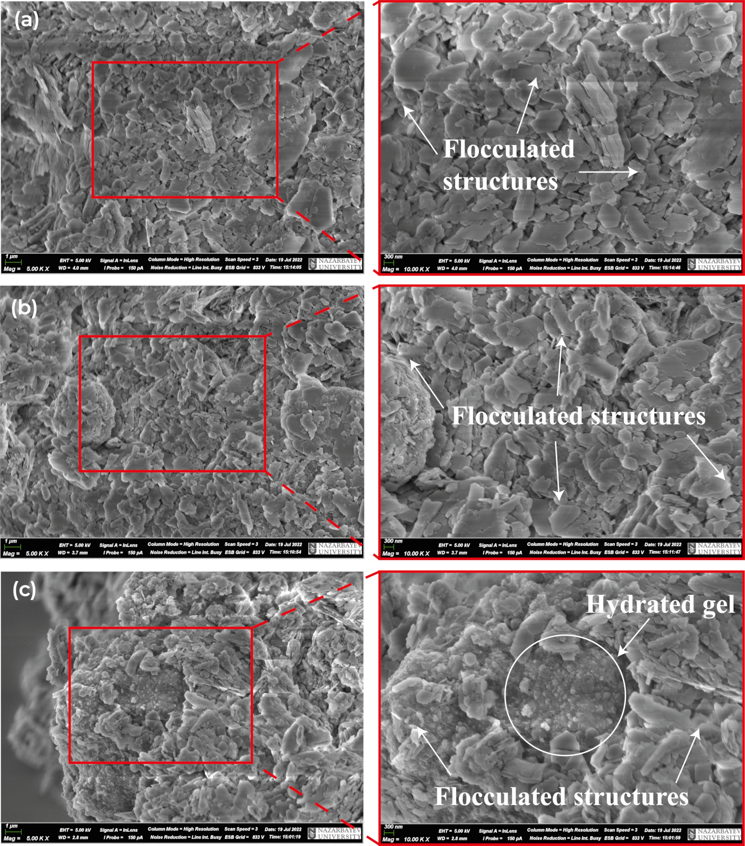
3.7. SEM Micrographs of Treated Soil

Figure 17 and Figure 18 present the results of a meticulous investigation into the microstructure and overall visual characteristics of kaolin clay samples that underwent treatment with varying BOF particle sizes and contents over 28 days. Upon careful examination of the micrographs depicting BOF A, BOF B, and BOF C in Figure 17, it is evident that the treated samples exhibit a porous structure, with a significant presence of pores. Nevertheless, an increase in the concentration of fine BOF particles led to a more flocculated surface, as evidenced by the progressive transformation of the sample’s texture.
A comparative analysis between Figure 17 and Figure 18 provides further insight into the influence of BOF content on the densification of clay samples. The results demonstrate that as the BOF content increases, there is a noticeable increase in the formation of hydrate gel, effectively filling the pores within the stabilized soil sample. This densification process significantly contributes to developing a stronger and more consolidated material. Furthermore, a detailed examination of BOF A, BOF B, and BOF C in Figure 17 reveals a relatively flattened surface, suggesting a weaker hydration process. This can be attributed to the lower concentration of fine BOF particles, which is critical in facilitating the hydration reaction. In contrast, as depicted in Figure 18, BOF D exhibits a more angular and flocculated structure, providing conclusive evidence of the mineral formation resulting from the reaction between kaolin clay and the free lime present in the BOF slag.
Figure 19 presents the microstructure of kaolin clay stabilized with the BOF slag, the lime-activated BOF slag, and the GGBFS–lime-activated BOF slag for 112 days. Compared to Figure 17 and Figure 18, a noticeable difference in the surface structure can be observed, as it appears more angular and fragmented. Lime enhances the hydration reaction of the BOF slag by interacting with the silica present in kaolin clay. The emergence of a dense matrix can be attributed to the coating of the reaction products generated during the hydration process. The presence of the GGBFS slag leads to a mixture that demonstrates more flaky granular particles. Hydrated gels, adhering to the interface and interparticle spaces, play a crucial role in binding the particles together. This process contributes to the overall strength and stability of the treated clay.

4. Discussion

The experimental results highlight the significant impact of BOF slag particle sizes and BOF content on the soil stabilization process. Finer particles and higher BOF slag contents contribute to increased UCS and V s , resulting in stronger and more stable soil. Furthermore, a longer curing time promotes the formation of cementitious bonds, further enhancing the material’s strength. The improvement in strength and rigidity can be primarily attributed to the chemical reaction between calcium oxide in the BOF slag and silica oxide in the soil, which forms cohesive cementitious bonds among soil particles. However, the presence of dicalcium silicate (C2S) in the BOF slag may result in slower strength development [15]. These observations emphasize the importance of considering lime content and curing duration in implementing BOF slag-based soil stabilization techniques. The findings provide valuable insights for optimizing the stabilization process and highlight the need for long-term evaluations to determine the most effective lime content for achieving the desired strength and performance in BOF slag-stabilized soils. Furthermore, incorporating GGBFS as a partial replacement for BOF slag enhances the strength and shear-wave velocity of stabilized soils, offering a cost-effective and sustainable solution for improving their performance.
The relationship between UCS and V s offers a valuable tool for evaluating the effectiveness of soil stabilization techniques. By measuring V s values, engineers and researchers can obtain reliable estimates of UCS, eliminating the need for additional time-consuming and costly tests. This streamlined approach enables efficient decision making in assessing treatment outcomes and optimizing soil stabilization strategies. In addition, the results of the microstructural analysis provide valuable insights into the hydration processes and the formation of gel structures within the stabilized clay. The presence of hydrated gels and the interlocking of particles contributed to the improved strength, stability, and consolidation of the treated clay samples. These microstructural changes were found to be influenced by the BOF particle size, lime activation, and GGBFS content.
The requirements of subgrade soil stabilization to assess the effectiveness of treated subgrade soils in terms of UCS, materials, curing time, and sample dimensions are summarized in Table 4. The minimum requirement for subgrade soil stabilization with lime, using the same sample dimensions, is 700 kPa, as proposed by the Federal Highway Administration [34]. Therefore, this value was considered as the target value in this research. In the case of using solely BOF slag, BOF D at a 30% replacement level exhibited the most promising results compared to BOF D at 10% and 20%, BOF A, BOF B, and BOF C. However, the UCS value of BOF D at 7 days (350 kPa) fell short of the minimum requirement specified in Table 4. Therefore, two activators (i.e., lime and GGBFS) were added to BOF D at a 30% replacement level to accelerate the BOF slag’s stabilization effect. Among the three different percentages of lime (1%, 3%, and 5%), 1% lime yielded the highest UCS value after 7 days of curing (549 kPa).
Consequently, the replacement of the BOF slag with GGBFS slag at 25% and 50% levels was investigated. Only when 1% lime was added to the mixture, along with the 50% replacement of BOF slag with GGBFS, the specimens achieved the minimum target value of 700 kPa according to Table 4, reaching a UCS value of 753 kPa. This combination proved successful in meeting the required strength criteria. This research underscores the significance of considering the appropriate combination of BOF slag, lime, and GGBFS slag to achieve the desired strength requirements. Moreover, the findings demonstrate that adding lime and partially replacing BOF slag with GGBFS slag can significantly enhance the stabilization effect of BOF slag, leading to improved UCS values. Further investigations should focus on the long-term performance and durability of the stabilized specimens. Additionally, field-scale studies and practical applications are needed to validate the effectiveness of the proposed mixtures in real-world engineering projects.

5. Conclusions

Based on the findings obtained from the conducted tests, this study highlights the following conclusions:
  • The finer range of the BOF slag (BOF D) (<0.075 mm) showed the highest UCS and V s , compared to BOF A (4.75–0.075 mm), BOF B (1.18–0.075 mm), and BOF C (0.3–0.075 mm). This can be attributed to the fact that the use of finer particles of BOF slag may result in a larger surface area contact between the soil skeleton and the free lime in the BOF slag.
  • Soil exhibited higher strength with an increase in the BOF content and curing time. A significant increase in UCS and Vs began after 28 days of curing.
  • The BE test results strongly correlated with the UCS test results. This indicates that the BE test can provide a reliable and non-destructive method for predicting the UCS performance of the soil–slag mixture.
  • For kaolin clay stabilization with the BOF slag, it is recommended to include 5% lime due to long-term hydration effects. Furthermore, replacing 50% of the BOF slag with ground granulated blast-furnace slag (GGBFS) enhances the stabilization process’s performance.
  • SEM images reveal that clay–BOF composite structures become more flocculated and smaller as the BOF particle size decreases, BOF content increases, and activators (lime and GGBFS) are incorporated. Voids are predominantly present in BOF A, BOF B, and BOF C due to the larger particle size. The effect of the hydrated gel, which enhances the rigidity of the soil–slag composite structure, intensifies with higher stabilizer contents.
  • According to the Federal Highway Administration [34], the minimum requirement of subgrade soil can be met for kaolin clay stabilization with BOF slag by adding 15% BOF slag, 15% GGBFS, and 1% lime based on the soil mass.
In conclusion, this study demonstrates the potential of BOF slag as an effective stabilizing agent for kaolin clay, contributing to a sustainable and environmentally friendly solution for problematic soils in civil engineering applications. The findings reveal that the optimal combination of BOF slag, GGBFS, and lime can achieve the desired geotechnical properties, meeting the minimum requirements for subgrade soil stabilization. Overall, the integration of BOF slag in soil stabilization processes addresses environmental concerns and presents a promising approach to improving weak soil layers in various construction applications. This research can guide engineers and researchers in designing efficient and sustainable soil stabilization techniques for geotechnical applications.

Author Contributions

Conceptualization, S.-W.M.; methodology, A.M. and S.-W.M.; investigation, A.M., A.B. and S.-W.M.; data curation, visualization, A.M., A.B. and S.O.O.; writing—original draft preparation, A.M. and S.-W.M.; resources, writing—review and editing, J.K. and A.S.; supervision, J.K. and S.-W.M.; project administration, funding acquisition, S.-W.M. All authors have read and agreed to the published version of the manuscript.

Funding

This research was funded by the Nazarbayev University, Collaborative Research Project (CRP) Grant No. 11022021CRP1508 and Faculty Development Competitive Research Grant Program (FDCRGP) Grant No. 20122022FD4115. Any opinions, findings, conclusions, or recommendations expressed in this material are those of the author(s) and do not necessarily reflect the views of Nazarbayev University.

Data Availability Statement

Data are available on request. The data are not publicly available due to privacy.

Conflicts of Interest

The authors declare no conflict of interest. The funders had no role in the design of the study; in the collection, analyses, or interpretation of data; in the writing of the manuscript; or in the decision to publish the results.

References

  1. Afrin, H. A review on different types soil stabilization techniques. Int. J. Transp. Eng. Technol. 2017, 3, 19–24. [Google Scholar] [CrossRef]
  2. Lakhanpal, A.; Chopra, A. A brief review on various methods and materials used for stabilization of soil. Int. Res. J. Eng. Technol. IRJET 2018, 5, 682–684. [Google Scholar]
  3. National Academies of Sciences, Engineering and Medicine. Recommended Practice for Stabilization of Subgrade Soils and Base Materials; National Academies of Sciences, Engineering and Medicine: Washington, DC, USA, 2009.
  4. Ifediniru, C.; Ekeocha, N.E. Performance of cement-stabilized weak subgrade for highway embankment construction in Southeast Nigeria. Geo-Engineering 2022, 13, 1. [Google Scholar] [CrossRef]
  5. Jumassultan, A.; Sagidullina, N.; Kim, J.; Ku, T.; Moon, S.W. Performance of cement-stabilized sand subjected to freeze-thaw cycles. Geomech. Eng. 2021, 25, 41–48. [Google Scholar]
  6. Sagidullina, N.; Abdialim, S.; Kim, J.; Satyanaga, A.; Moon, S.W. Influence of Freeze—Thaw Cycles on Physical and Mechanical Properties of Cement-Treated Silty Sand. Sustainability 2022, 14, 7000. [Google Scholar] [CrossRef]
  7. Vinoth, G.; Moon, S.W.; Kim, J.; Ku, T. Effect of Fine Particles on Cement Treated Sand. In Proceedings of the Springer Series in Geomechanics & Geoengineering, Vienna, Austria, 13–16 August 2018. [Google Scholar] [CrossRef]
  8. Bisserik, A.; Kim, J.; Satyanaga, A.; Moon, S.W. Characterization of CSA Cemented-Treated Sands via Discrete Element Method. AIP Conf. Proc. 2021, 2441, 030001. [Google Scholar] [CrossRef]
  9. Subramanian, S.; Moon, S.W.; Ku, T. Effect of Gypsum on the strength of C.S.A. treated sand. In Proceedings of the 16th Asian Regional Conference (A.R.C.) on Soil Mechanics and Geotechnical Engineering, Taipei, Taiwan, 14–18 October 2019; Available online: https://yo-1.ct.ntust.edu.tw:8887/tgssp/file/16ARC/file/SA10-02-003_GEOSS-005.pdf (accessed on 12 October 2023).
  10. Vaiana, R.; Oliviero Rossi, C.; Perri, G. An eco-sustainable stabilization of clayey road subgrades by lignin treatment: An overview and a comparative experimental investigation. Appl. Sci. 2021, 11, 11720. [Google Scholar] [CrossRef]
  11. Perri, G.; De Rose, M.; Domitrović, J.; Vaiana, R. CO2 Impact Analysis for Road Embankment Construction: Comparison of Lignin and Lime Soil Stabilization Treatments. Sustainability 2023, 15, 1912. [Google Scholar] [CrossRef]
  12. Pushpakumara, B.H.J.; Mendis, W.S.W. Suitability of Rice Husk Ash (RHA) with lime as a soil stabilizer in geotechnical applications. Geo-Engineering 2022, 13, 4. [Google Scholar] [CrossRef]
  13. Mekonnen, E.; Amdie, Y.; Etefa, H.; Tefera, N.; Tafesse, M. Stabilization of expansive black cotton soil using bioenzymes produced by ureolytic bacteria. Geo-Engineering 2022, 13, 10. [Google Scholar] [CrossRef]
  14. Diniz, D.H.; de Carvalho, J.M.F.; Mendes, J.C.; Peixoto, R.A.F. Blast oxygen furnace slag as chemical soil stabilizer for use in roads. J. Mater. Civ. Eng. 2017, 29, 04017118. [Google Scholar] [CrossRef]
  15. Poh, H.; Ghataora, G.S.; Ghazireh, N. Soil Stabilization Using Basic Oxygen Steel Slag Fines. J. Mater. Civ. Eng. 2006, 18, 229–240. [Google Scholar] [CrossRef]
  16. Salimi, M.; Ghorbani, A. Mechanical and compressibility characteristics of a soft clay stabilized by slag-based mixtures and geopolymers. Appl. Clay Sci. 2020, 184, 105390. [Google Scholar] [CrossRef]
  17. Fisher, L.V.; Barron, A.R. The recycling and reuse of steelmaking slags—A review. Resour. Conserv. Recycl. 2019, 146, 244–255. [Google Scholar] [CrossRef]
  18. O’Connor, J.; Nguyen, T.B.T.; Honeyands, T.; Monaghan, B.; O’Dea, D.; Rinklebe, J.; Vinu, A.; Hoang, S.A.; Singh, G.; Kirkham, M.B.; et al. Production, characterisation, utilisation, and beneficial soil application of steel slag: A review. J. Hazard. Mater. 2021, 419, 126478. [Google Scholar] [CrossRef] [PubMed]
  19. Shi, C.; Qian, J. High performance cementing materials from industrial slags—A review. Resour. Conserv. Recycl. 2000, 29, 195–207. [Google Scholar] [CrossRef]
  20. Cikmit, A.A. Engineering Properties of Stabilized Marine Clay Using Basic Oxygen Furnace Steel Slag: Strength Development and Expansion Behaviour. Ph.D. Thesis, Hiroshima University, Hiroshima, Japan, 2019. [Google Scholar]
  21. Goodarzi, A.; Salimi, M. Stabilization treatment of a dispersive clayey soil using granulated blast furnace slag and basic oxygen furnace slag. Appl. Clay Sci. 2015, 108, 61–69. [Google Scholar] [CrossRef]
  22. Kang, G.; Cikmit, A.A.; Tsuchida, T.; Honda, H.; Kim, Y.S. Strength development and microstructural characteristics of soft dredged clay stabilized with basic oxygen furnace steel slag. Constr. Build. Mater. 2019, 203, 501–513. [Google Scholar] [CrossRef]
  23. Cikmit, A.A.; Tsuchida, T.; Kang, G.; Hashimoto, R.; Honda, H. Particle-size effect of basic oxygen furnace steel slag in stabilization of dredged marine clay. Soils Found. 2019, 59, 1385–1398. [Google Scholar] [CrossRef]
  24. Zhang, X.; Shu, C.; Fujii, M.; Wu, Y.; Ye, P.; Bao, Y. Numerical and experimental study on water-heat-salt transport patterns in shallow bare soil with varying salt contents under evaporative conditions: A comparative investigation. J. Hydrol. 2023, 621, 129564. [Google Scholar] [CrossRef]
  25. ASTM/D1921; Standard Test Methods for Particle Size (Sieve Analysis) of Plastic Materials. ASTM International: West Conshohocken, PA, USA, 2018.
  26. ASTM/D4318; Standard Test Methods for Liquid Limit, Plastic Limit, and Plasticity Index of Soils. ASTM International: West Conshohocken, PA, USA, 2017.
  27. ASTM/D854; Standard Test Methods for Specific Gravity of Soil Solids by Water Pycnometer. ASTM International: West Conshohocken, PA, USA, 2014.
  28. ASTM/D698; Standard Test Methods for Laboratory Compaction Characteristics of Soil Using Standard Effort. ASTM International: West Conshohocken, PA, USA, 2007.
  29. ASTM/C127; Standard Test Method for Relative Density (Specific Gravity) and Absorption of Coarse Aggregate. ASTM International: West Conshohocken, PA, USA, 2015.
  30. ASTM/C128; Standard Test Method for Relative Density (Specific Gravity) and Absorption of Fine Aggregate. ASTM International: West Conshohocken, PA, USA, 2022.
  31. ASTM/C136; Standard Test Method for Sieve Analysis of Fine and Coarse Aggregates. ASTM International: West Conshohocken, PA, USA, 2006.
  32. ASTM/D2166; Standard Test Method for Unconfined Compressive Strength of Cohesive Soil. ASTM International: West Conshohocken, PA, USA, 2003.
  33. ASTM/D8295; Standard Test Method for Determination of Shear Wave Velocity and Initial Shear Modulus in Soil Specimens using Bender Elements. ASTM International: West Conshohocken, PA, USA, 2019.
  34. Department Transportation and Federal Administration. Standard Specifications for Construction of Roads and Bridges on Federal Highway Projects; Department Transportation and Federal Administration: Washington, DC, USA, 2014.
  35. Portland Cement Association. Soil-Cement Laboratory Handbook; Portland Cement Association: Washington, DC, USA, 1992. [Google Scholar]
  36. Gass, B.; Ventura, D.; De Beer, M. Erodibility of Cemented Materials; National Department of Transport: Pretoria, South Africa, 1993.
  37. American Association of State Highway and Transportation Officials. Mechanistic Empirical Pavement Design Guide A Manual of Practice; American Association of State Highway and Transportation Officials: Washington, DC, USA, 2019.
  38. Jameson, G. Guide to Pavement Technology Part 4D: Stabilised Materials Edition 2.1; Austroads Ltd.: Sydney, NS, Australia, 2019. [Google Scholar]
  39. Indian Roads Congress. Guidelines for the Design of Flexible Pavements for Low Volume Rural Roads; Indian Roads Congress: New Delhi, India, 2015.
  40. Syed, I.M.; Scullion, T. Performance evaluation of recycled and stabilized bases in Texas. Transp. Res. Rec. 2001, 1757, 14–21. [Google Scholar] [CrossRef]
  41. Joel, M.; Agbede, I.O. Mechanical-cement stabilization of laterite for use as flexible pavement material. J. Mater. Civ. Eng. 2011, 23, 146–152. [Google Scholar] [CrossRef]
  42. Portelinha, F.H.; Lima, D.C.; Fontes, M.P.; Carvalho, C.A. Modification of a lateritic soil with lime and cement: An economical alternative for flexible pavement layers. Soils Rocks 2012, 35, 51–63. [Google Scholar] [CrossRef]
  43. Jaritngam, S.; Somchainuek, O.; Taneerananon, P. An investigation of lateritic soil cement for sustainable pavements. Indian J. Sci. Technol. 2012, 5, 3603–3606. [Google Scholar] [CrossRef]
  44. Shankar, A.U.; Suresha, S.N.; Kashinath, B. Characterisation of lateritic soil modified with pond ash and cement. Indian Highw. 2008, 36, 21–27. [Google Scholar]
  45. InfraRYL. Code of Building Practice, Infrastructure, Part 1: Roads and Areas; Rakennustieto Oy: Helsinki, Finland, 2010. [Google Scholar]
Figure 1. The experimental procedure’s flowchart.
Buildings 13 02962 g001
Figure 2. Materials used in this study.
Buildings 13 02962 g002
Figure 3. Gradation of BOF slag and kaolin clay.
Buildings 13 02962 g003
Figure 4. Different particle sizes of BOF slag.
Buildings 13 02962 g004
Figure 5. X-ray diffraction of (a) kaolin clay,(b) BOF slag, (c) Lime, and (d) GGBFS.
Buildings 13 02962 g005
Figure 6. Sample preparation.
Buildings 13 02962 g006
Figure 7. Test methodology of (a) UCS and (b) BE.
Buildings 13 02962 g007
Figure 8. First-arrival picking method used for analyzing BE test results.
Buildings 13 02962 g008
Figure 9. Standard proctor test results with (a) different BOF particle sizes, (b) BOF content, (c) lime content, and (d) GGBFS content.
Buildings 13 02962 g009
Figure 10. Results of (a) BE and (b) UCS tests with different particle sizes of BOF slag from 3 to 28 curing days.
Buildings 13 02962 g010
Figure 11. Stress–strain behavior with different particle sizes after 28 days of curing.
Buildings 13 02962 g011
Figure 12. The results of (a) BE and (b) UCS tests of BOF D from 3 to 112 curing days.
Buildings 13 02962 g012
Figure 13. Stress–strain behavior with different BOF D contents after 112 days of curing.
Buildings 13 02962 g013
Figure 14. The results of (a) BE and (b) UCS tests of BD30L1, BD30L3, and BD30L5 from 3 to 112 curing days.
Buildings 13 02962 g014
Figure 15. The results of (a) BE and (b) UCS tests of BD30L1G25 and BD30L1G50 from 3 to 112 curing days.
Buildings 13 02962 g015
Figure 16. Relationships between UCS and V s .
Buildings 13 02962 g016
Figure 17. SEM results for 28-day-cured (a) BOF A, (b) BOF B, and (c) BOF C.
Buildings 13 02962 g017
Figure 18. SEM results for 28-day-cured (a) BOF D 10%, (b) BOF D 20%, and (c) BOF D 30%.
Buildings 13 02962 g018
Figure 19. SEM results for 112-day-cured (a) BD30, (b) BD30L5, and (c) BD30L5G50.
Buildings 13 02962 g019
Table 1. Physical characteristics of kaolin clay and BOF slag.
TypeCharacteristicValueStandard
Kaolin clayUSCS classificationMHASTM D1921 [25]
Plastic limit, %33.13ASTM D4318 [26]
Liquid limit, %53.57ASTM D4318 [26]
Plasticity index, %20.45ASTM D4318 [26]
Fine, %>80QICPIC
Specific gravity2.44ASTM D854 [27]
Optimum moisture content, %19.3ASTM D698 [28]
Maximum dry density, k g / m 3 1209ASTM D698 [28]
BOF slagSpecific gravitycoarse aggregate3.18ASTM C127 [29]
fine aggregate3.14ASTM C128 [30]
Absorption rate, %coarse aggregate3.58ASTM C127 [29]
fine aggregate3.05ASTM C128 [30]
Maximum particle size, mm19ASTM C136 [31]
Coarse particles (>0.075 mm), %99.5ASTM C136 [31]
Fine particles (<0.075 mm), %0.5ASTM C136 [31]
Table 2. The chemical composition of the materials (weight %).
PropertiesKaolin ClayBOF SlagGGBFSLime
MgO-8.813.10.12
Al2O338.141.164.47<0.1
SiO251.6810.2616.120.23
CaO0.2437.4532.6980.33
MnO-3.310.53<0.1
Fe2O30.4827.420.47<0.1
K2O0.46<0.10.64-
Ti2O0.580.561.04<0.1
SO3<0.10.381.48-
V2O5-0.69<0.1<0.1
Table 3. Mixture design.
Effect ofBOF TypeBOF (%)Lime (%)BOF/GGBFS (%)Curing DaysAbbreviations
BOF particle sizeBOF A30 3, 7, 14, 28BA30
BOF B303, 7, 14, 28BB30
BOF C303, 7, 14, 28BC30
BOF D303, 7, 14, 28, 56, 112BD30
BOF content BOF D10 3, 7, 14, 28, 56, 112BD10
BOF D203, 7, 14, 28, 56, 112BD20
BOF D303, 7, 14, 28, 56, 112BD30
Lime contentBOF D301%-3, 7, 14, 28, 56, 112BD30L1
BOF D303%-3, 7, 14, 28, 56, 112BD30L3
BOF D305%-3, 7, 14, 28, 56, 112BD30L5
GGBFS contentBOF D301%75/253, 7, 14, 28, 56, 112BD30L1G25
BOF D301%50/503, 7, 14, 28, 56, 112BD30L1G50
Table 4. Requirements for subgrade soil stabilization.
ApplicationsUCS (MPa)Stabilizing MaterialsCuring Time (Days)Mold DxH (mm)References
Subgrade (for stabilized drainable base in cold regions to resist frost deterioration)0.7Lime/Soil750 × 100Federal Highway Administration [34]
1Lime/Fly ash/Soil750 × 100
1.4Cement/Soil; Cement/Fly ash/Soil; Fly ash/Soil7101.6 × 116.8
Medium-to-high-volume roads for sub-base/base2.068Cement7101.6 × 116.84Portland Cement Association [35]; Gass [36]
Sub-base/Subgrade/Base1.72–5.17Cement7100 × 115MEPDG [37]
Lime/Fly ash; Cement/Fly ash28
Bound pavement materials (stabilizer > 3%)2Cement28105 × 115.5Austroads [38]
Subgrade/lightly bound pavement1–2Cement7
Sub-base0.75–1.5Lime/Fly ash750 × 100IRC 37 [39]
Base4.5–7Cement28
Subgrade (for the base in recycled and stabilized pavement layers)1.38Cement7150 × 250Syed and Scullion [40]
Base pavement2.702Cement/Sand738 × 76Joel and Agbade [41]
Pavement in roadways0.6Lime7100 × 127Portelinha et al. [42]
Pavement in roadways1Cement7100 × 128
Base course construction material2.22Cement7101.6 × 116.8Jaritngam et al. [43]
Road construction1Cement/Pond ash7100 × 127.3Ravi et al. [44]
Base/Sub-base/Subgrade3–8Cement/Soil7N/AInfraRYL [45]
5–13Cement/Soil28
1–2GGBFS/Soil28
Disclaimer/Publisher’s Note: The statements, opinions and data contained in all publications are solely those of the individual author(s) and contributor(s) and not of MDPI and/or the editor(s). MDPI and/or the editor(s) disclaim responsibility for any injury to people or property resulting from any ideas, methods, instructions or products referred to in the content.

