Article

Full-Scale Assessment of Seismic and Wind Load Performance in the Design of a Flexible Solar-Shading Double-Skin Façade

by
José Pérez-Fenoy
1,
Carlos Rivera-Gómez
2,*,
Jorge Roa-Fernández
2 and
Carmen Galán-Marín
2
1
Andalusian Ceramic Technology Centre, INNOVARCILLA Foundation, 23710 Bailen, Spain
2
Department of Building Construction, School of Architecture, Universidad de Sevilla, 41012 Seville, Spain
*
Author to whom correspondence should be addressed.
Buildings 2023, 13(12), 2945; https://doi.org/10.3390/buildings13122945
Submission received: 31 October 2023 / Revised: 17 November 2023 / Accepted: 21 November 2023 / Published: 25 November 2023
(This article belongs to the Special Issue Challenges in Seismic Analysis and Assessment of Buildings)

Abstract

:
Cable-supported façades represent a novel approach in the design and technology of double skin façades (DSFs). This type of system not only offers flexibility in terms of exterior finishes, but also regulates the access of solar radiation, thereby transforming the appearance of the building in response to varying daylight conditions. However, the structural performance of these façades under wind, impact, and seismic loads remains an active area of research. The study is a groundbreaking work that experimentally evaluates the wind and seismic behaviour of these type of façades. The methodology used for the evaluation of flexible masonry facades includes laboratory tests analysing the individual capacity of the connections and materials of the system under standardized and non-standardized procedures. A full-scale experimental sub-assembly specimen of a representative module of the façade is also subjected to uniformly distributed pressures of wind load tests, as well as hard body and soft body impact tests. The setup considered the border conditions, tension loads, and actual materials. Furthermore, the earthquake assessment includes tests of full-scale specimens subjected to these demands. The results show up to 30% enhanced performance relative to similar systems reported in the literature. Furthermore, research findings facilitated the refinement and redesign of the system components, thereby validating the DSF case study.

1. Introduction

Double skin façades (DSFs), also known as ventilated cladding systems, are a widely used construction method in the building industry, employed in both new construction projects and building refurbishment [1]. DSFs have become popular in contemporary building design due to their energy-efficient and visually appealing characteristics. This façade solution involves the installation of vertical or horizontal elements anchored to the structural and non-structural components of a building, upon which an external cladding is mounted, creating a ventilated air cavity whose dimensions depend on the spacing between the outer cladding elements. In DSFs, the importance of analysing the impact of dynamic loads on both structural and non-structural components cannot be overstated. This evaluation is crucial in ensuring the safety and integrity of the whole building and its occupants under various conditions, including normal service conditions and extreme loads resulting from events such as windstorms, earthquakes, or explosions [2,3]. While structural elements often receive primary attention due to their role in maintaining the stability of a building, non-structural elements such as internal partitions, façades, and windows also warrant significant consideration [4]. These elements not only constitute a major portion of construction costs but also require careful evaluation to ensure their optimal performance. To assess the capacity of non-structural components and connections, it is recommended to implement both analytical and experimental programs [5,6]. Such evaluations typically fall outside the purview of building codes. Although these codes do provide guidance on estimating minimum design forces, more specialized methodologies or experimental testing may be necessary for complex systems. These additional measures serve dual purposes: they enhance our understanding of the performance and strength of these components, and they help determine whether forces exceeding those specified in building code requirements are possible. This dual approach ensures a comprehensive understanding of both structural and non-structural elements, ultimately contributing to safer and more resilient buildings. The construction process of a DSF includes several different stages. Firstly, there are the substructure’s supporting members, consisting of vertical and/or horizontal elements that are attached to both the structural and non-structural elements of the building. These elements serve as the framework for the cladding system. Secondly, there is the construction of the exterior cladding, in which a durable external cladding material is affixed to the framework. This outer layer not only protects the building from environmental factors but also plays a crucial role in the aesthetics of the structure. Finally, there is the air cavity formation, in which the gap between the external cladding and the structural element of the building creates an air cavity. The dimensions of this cavity are determined by the spacing between the exterior cladding components. This cavity allows for natural ventilation and acts as a thermal buffer.
In contemporary architectural practices, increasingly complex façade systems, such as DSFs, entail innovative solutions that consider several critical structural factors, as follows: (a) massiveness: the overall volume and spatial arrangement of the building can significantly influence the design and performance of the façade. (b) Flow characteristics: the façade’s permeability or continuity can lead to the generation of vortices or turbulence, impacting the building’s thermal and acoustic comfort. (c) Material selection: the use of heavy materials such as stone, masonry, glass, and steel can affect the façade’s structural integrity and aesthetic appeal. Finally, (d) complex geometries: the incorporation of intricate elements such as perforated elements, panels, tiles, and veneers can result in unexpected responses, due to their interaction with environmental factors. Therefore, a comprehensive understanding of these factors is essential for designing effective and sustainable façade systems. A recent alternative for DSFs involves the use of flexible elements to support the external cladding components [7]. This variant introduces an innovative approach to the traditional construction method, offering distinct advantages, among which are: adaptability, given that flexible elements can accommodate irregularities in the building’s structure, allowing for more versatile and creative designs [8]; a better dynamic response (since the flexibility of these elements enables the cladding system to adapt to external forces, such as wind loads or seismic activity, without compromising its integrity [9,10,11,12]; and, often, an enhanced insulation, because by incorporating flexible elements, the insulation properties of the cladding system can be improved, further enhancing the building’s energy efficiency [13].
Regulatory frameworks play a crucial role in ensuring the safety and performance of DSFs. However, usually, these regulations often focus primarily on structural elements or provide general requirements for various façade components [7,14]. The validation of DSFs involves a comprehensive examination of their components, performance, and interactions. This process generally encompasses different means: finite element modelling (FEM) and calculation tools, which are indispensable for analysing the performance of building systems; laboratory tests that are essential for assessing the physical properties and performance of building components; and pilot-scale testing that involves the construction and evaluation of small-scale and full-scale building prototypes. These prototypes replicate key aspects of the system and allow researchers to assess its performance in a practical setting. Pilot-scale tests provide valuable data on factors such as structural integrity, energy efficiency, and occupant comfort. The whole validation process aims to ensure that the system meets regulatory requirements, while also accommodating innovative design approaches and materials.
Most studies available in the scientific literature are related to the lighting control and/or energy efficiency performance of DSF systems. Examples of this approach are the works of Hoffman et al. [15], Rizki et al. [16], or Yun et al. [17]. In recent years, the optimisation of both functions has started to be based on statistical models, proposing different algorithms to improve the design features of these façades [18,19]. Recent scientific literature has highlighted the use of the finite element method (FEM) in the analysis of DSFs. For instance, a study conducted by Camilla Lops et al. [20] used computational fluid dynamics (CFD), a subset of FEM, to simulate the behaviour of naturally ventilated double skin facades. The study compared various double facade configurations by adopting bi- and three-dimensional domains and different turbulence models. In another study, Süleyman İpek & Esra Mete Güneyisi [21] used FEM to simulate the behaviour of concrete-filled double skin steel tubular (CFDST) composite columns with a circular hollow section. In addition to these, there are several other studies that have utilized FEM for analysing ventilated facades and double skin systems. These include studies by Choi W, Joe J, Kwak Y, and Huh JH [22], which provide valuable insights into the application of FEM in this field. These studies demonstrate the potential of FEM in analysing complex building systems such as ventilated facades and double skin systems. However, more research is needed to fully understand and optimize these systems’ performances under various conditions.
While there is extensive research on the energy efficiency performance of DSFs, studies on the structural performance of heavy ventilated cable-supported facades are limited [23,24,25,26]. The interplay between wind and earthquake loads with permeable DSFs can be critical, especially when the input load frequency aligns with the facade’s natural frequency, leading to a resonance phenomenon. This paper aims to address this research gap by presenting the results of an experimental program designed to assess the performance of such non-structural components under lateral loads. The evaluation methodology encompassed laboratory and full-scale tests, to ascertain the dynamic properties of the façade and estimate the capacity of individual components and the overall system, analysing especially those loads which, by their nature, require full-scale prototypes, namely loads and deformations due to seismic, wind, and impact effects of particular interest in non-rigid façade systems. The applied methodology is also intended to guide the system-testing iteration and its usefulness in the design process. This work aims, therefore, to delve into the study, evaluation, and validation of a cable net suspended DSF. Two of the main goals of the research are collecting and correlating the results of the experimental evaluation conducted on the DSF system, and to perform simulations and experimental procedures based on different evaluation guides for DSF elements and the necessary adaptation to apply them to the case study analysed.

2. Materials and Methods

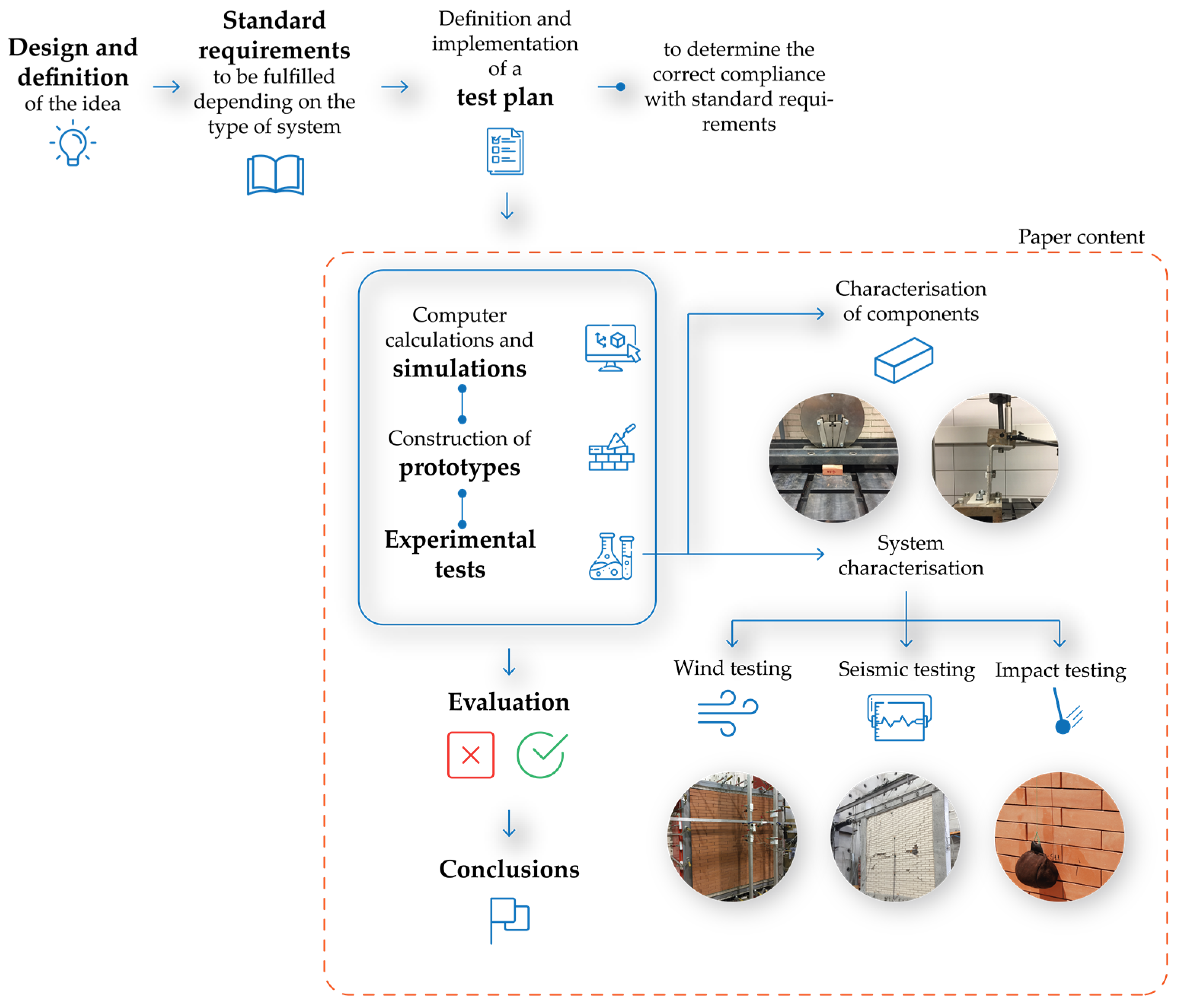
2.1. Methodology Overview
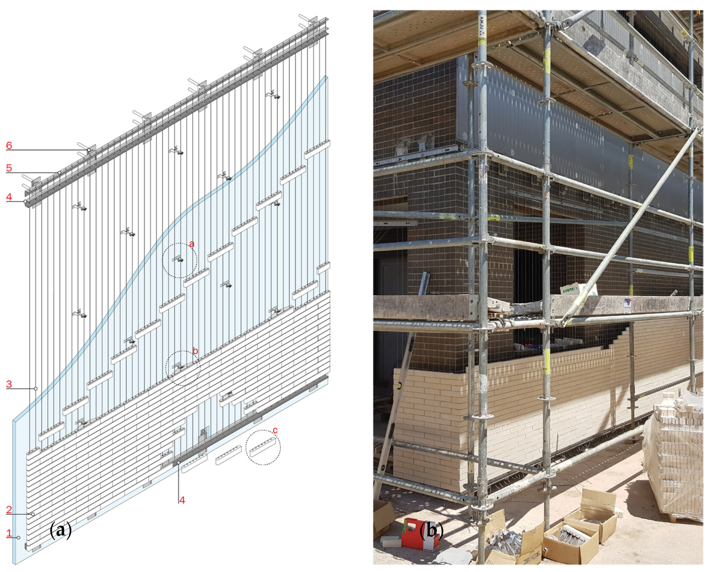
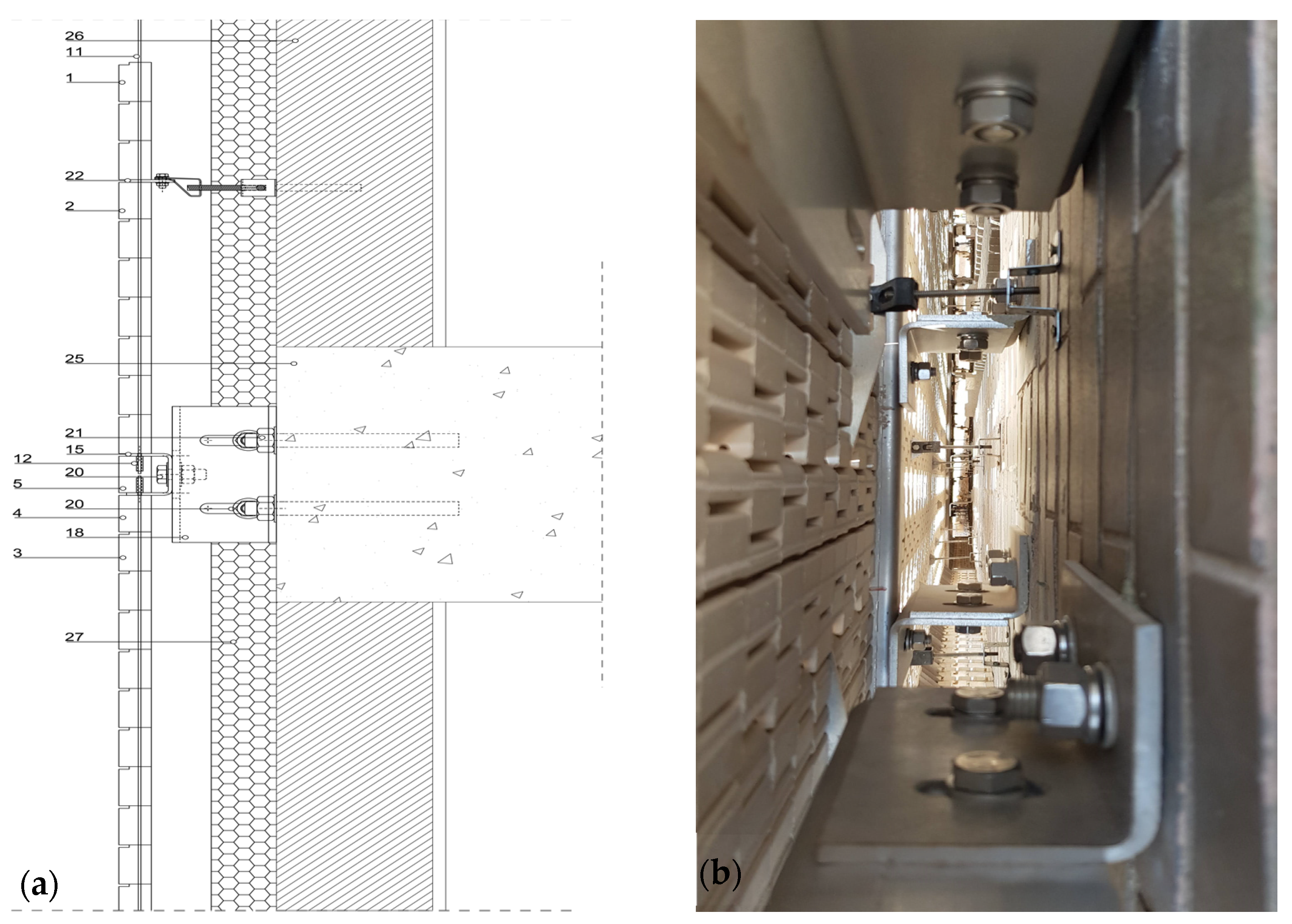
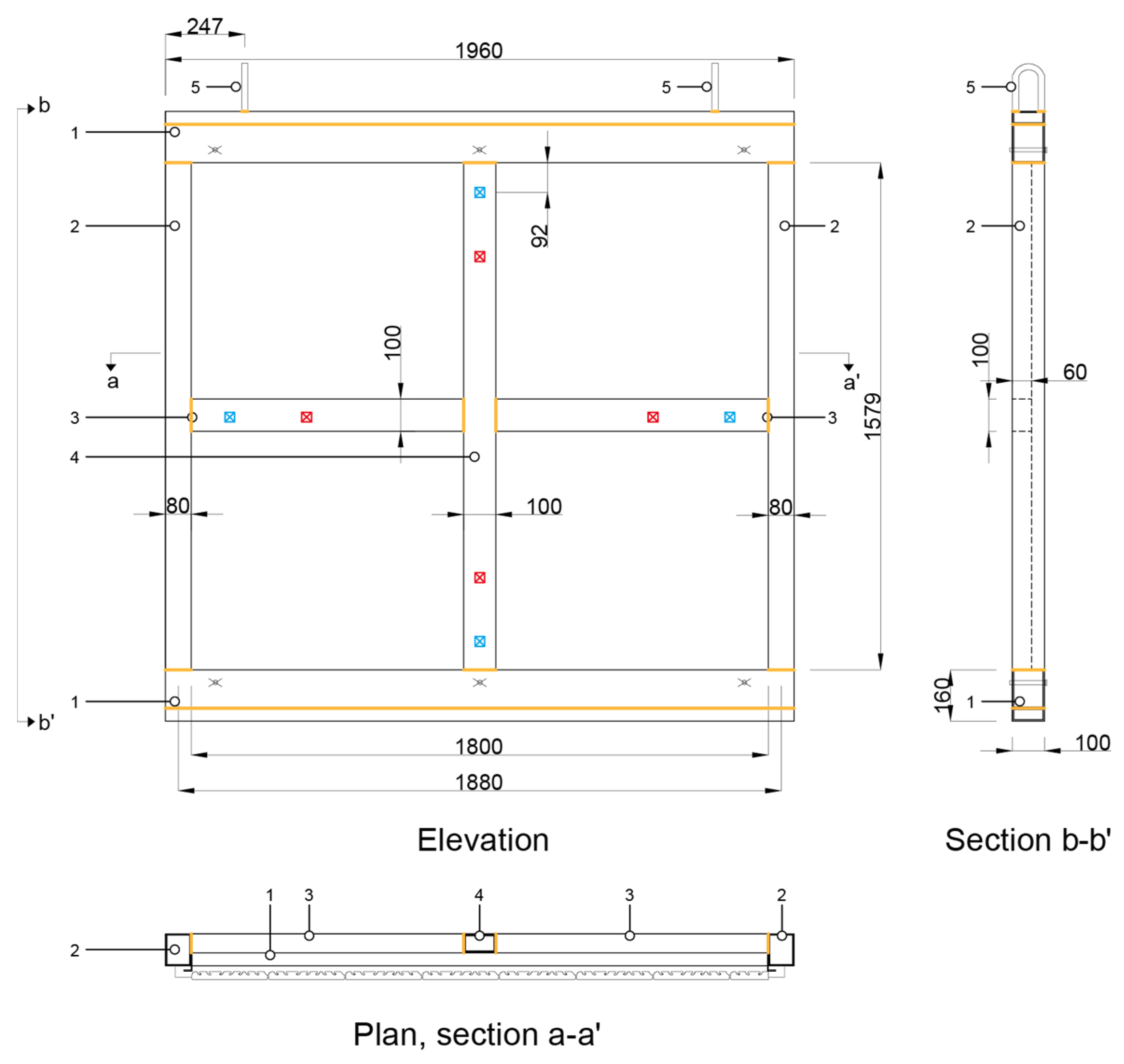
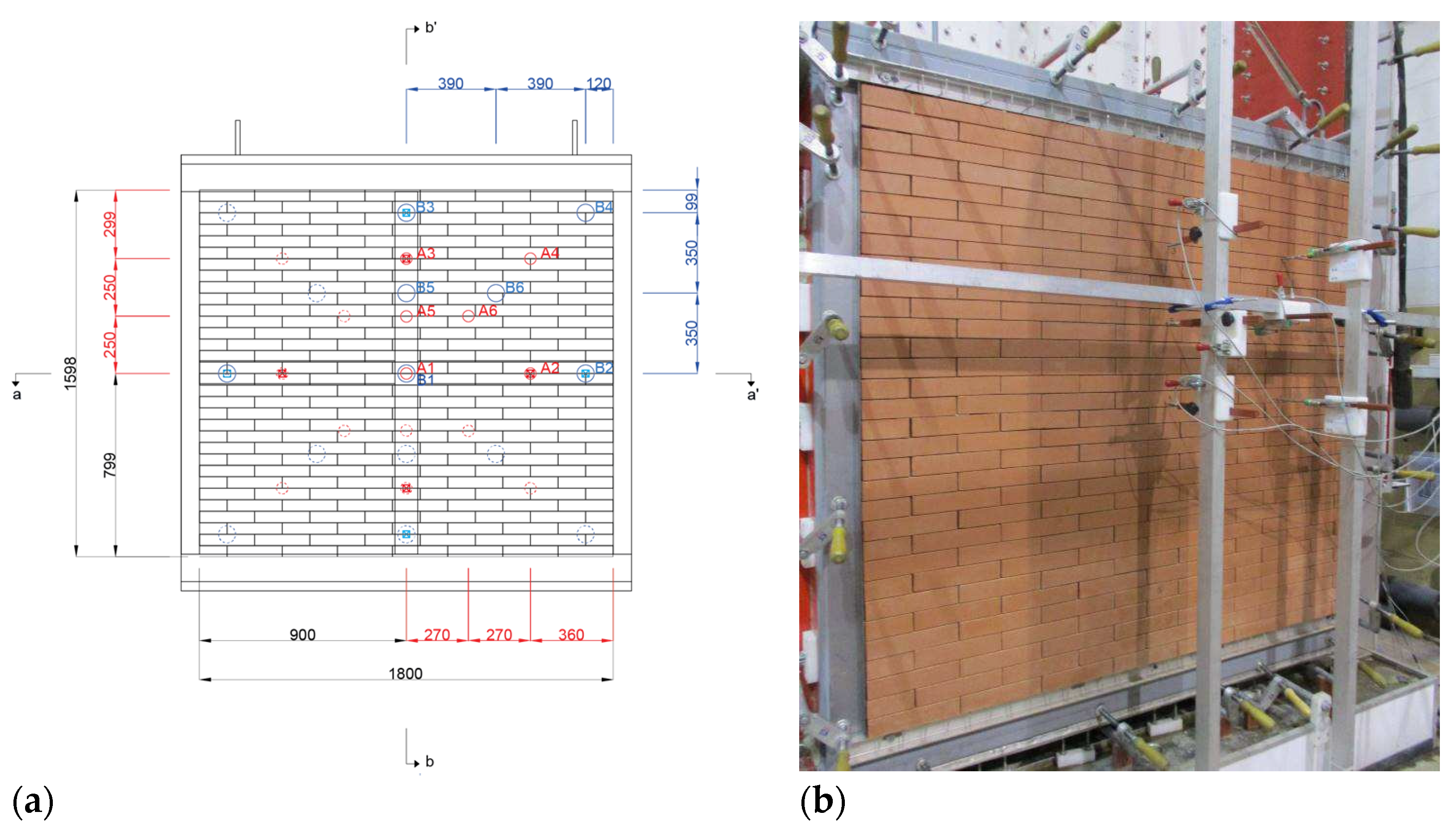
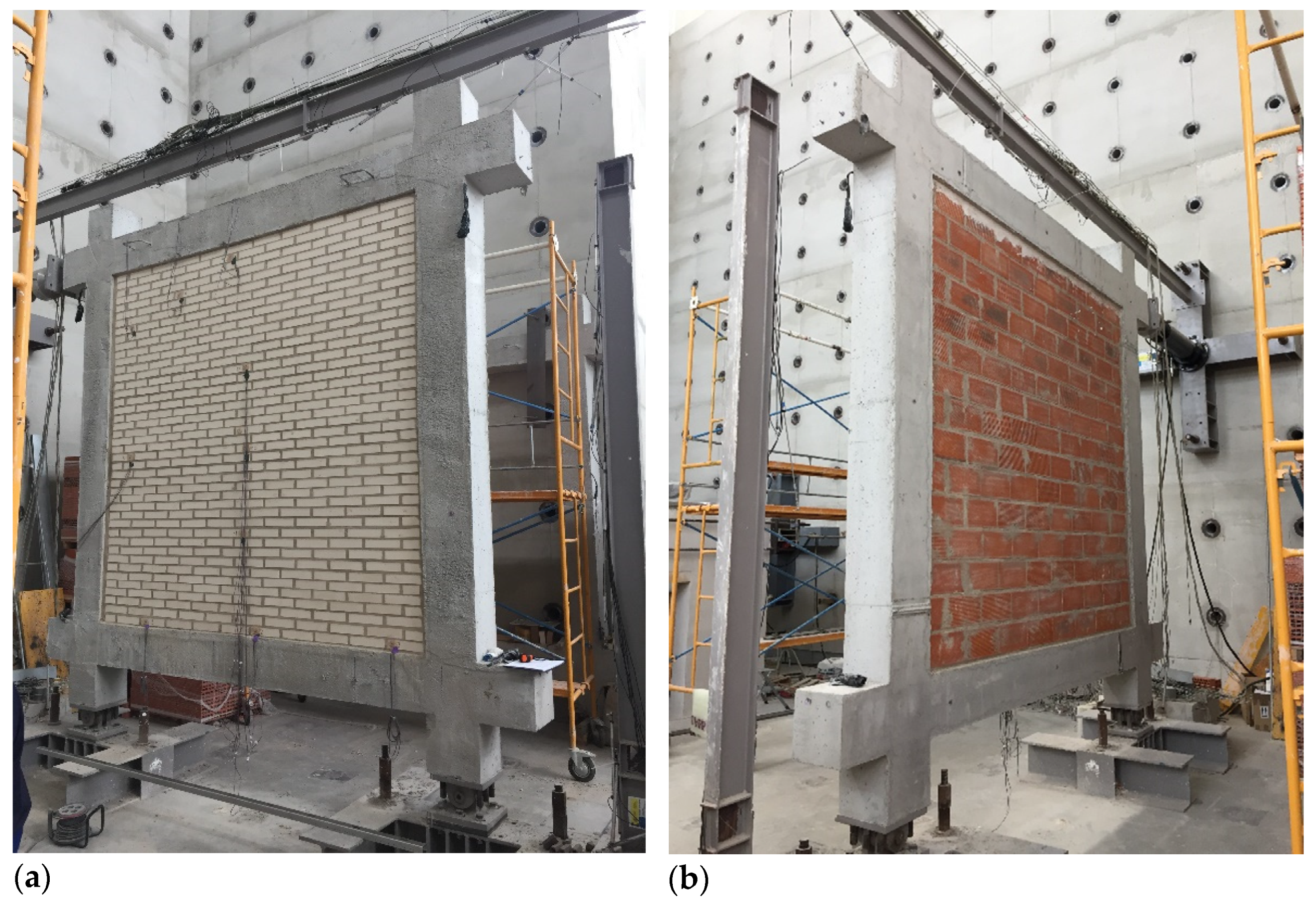
The methodological process of this research is divided into five phases. In the first one, the elements of the system are designed and defined. Once an adequate degree of suitability has been reached, in the second phase the regulatory requirements of the system and its components are studied and checked. In the third phase, a test plan is completely defined to evaluate the system performance at both component and constructive system levels. During the fourth phase, the guidelines indicated in the test plan are executed, including component testing under reference standards or by adapting some test procedures due to the uniqueness of some elements. In addition to the characterization of individual components, tests are also carried out to check the interaction and compatibility between elements, as well as full-scale experimental tests of the complete system. The whole process of building full-scale experimental prototypes for testing also allows a real evaluation of the whole construction process foreseen for the system and a redesign, if necessary, in case of unforeseen events. The fourth phase is complemented by the possibility of carrying out computer simulations to check the suitability of elements, or to extrapolate the experimental results to other situations that have not been possible to test on a real scale due to the great variety of possible solutions. The fifth phase is the last phase of the methodology. In this phase, all the results obtained in previous phases are collected and studied, and it is decided whether they are viable based on objective parameters and how the system is evaluated; namely, positively or negatively. It may also happen that a negative evaluation leads, in a cyclical way, to a redesign of elements in the first phase. The diagram displayed in Figure 1 shows the methodology used throughout the design and validation of the DSF system and which components could be applicable to the improvement process of other similar building façade systems. This work is focused on the actions referred to in the fourth and fifth phases, as well as the regulations applicable to the execution of the tests necessary to characterize the ventilated façade system. In the development of the text, the actions related to wind, seismic, and external impact tests are described. The characterization values of the individual components and the interaction between them are also indicated, specifying the regulations under which they have been tested.

2.2. DSF Case Study

In order to clearly describe the system, in addition to the description of components, several images of the different parts of the system are presented in this section. The DSF system, analysed as a case study, is based on the assembly of small-sized ceramic tiles on a framework of vertical cables fixed to horizontal U-profiles, which are responsible for supporting the weight of the ceramic pieces, as well as the traction of the cables. The vertical wiring is used to insert and fix the position of the ceramic pieces, as well as to transmit the actions on the outer skin to the horizontal profiles, which are responsible for transmitting the loads to the supporting structure, together with the support brackets on which the horizontal profiles are fixed. Together with these elements, retaining devices are installed to absorb the pressures and suction generated by the wind load on the façade (Figure 2 and Figure 3). In addition to these characteristic parts of the system, a series of auxiliary elements are designed which are necessary for the correct assembly of the system; specifically, L-shaped profiles, which are placed at the crown of the façade and which, once the wall panel is completed, are removed so that they can be reused in a different panel.
The construction system components are therefore grouped into the following categories: a set of shaped ceramic tiles (Figure 4), which integrates all the possible pieces to be installed on the cable-net framework; a supporting device, which contains all the necessary elements to support the ceramic pieces, such as cables, horizontal profiles, etc.; a retaining device, responsible for supporting the action of the wind on the surface of the façade; and all the auxiliary components, which are necessary for the correct assembly of the system on site (Figure 5).

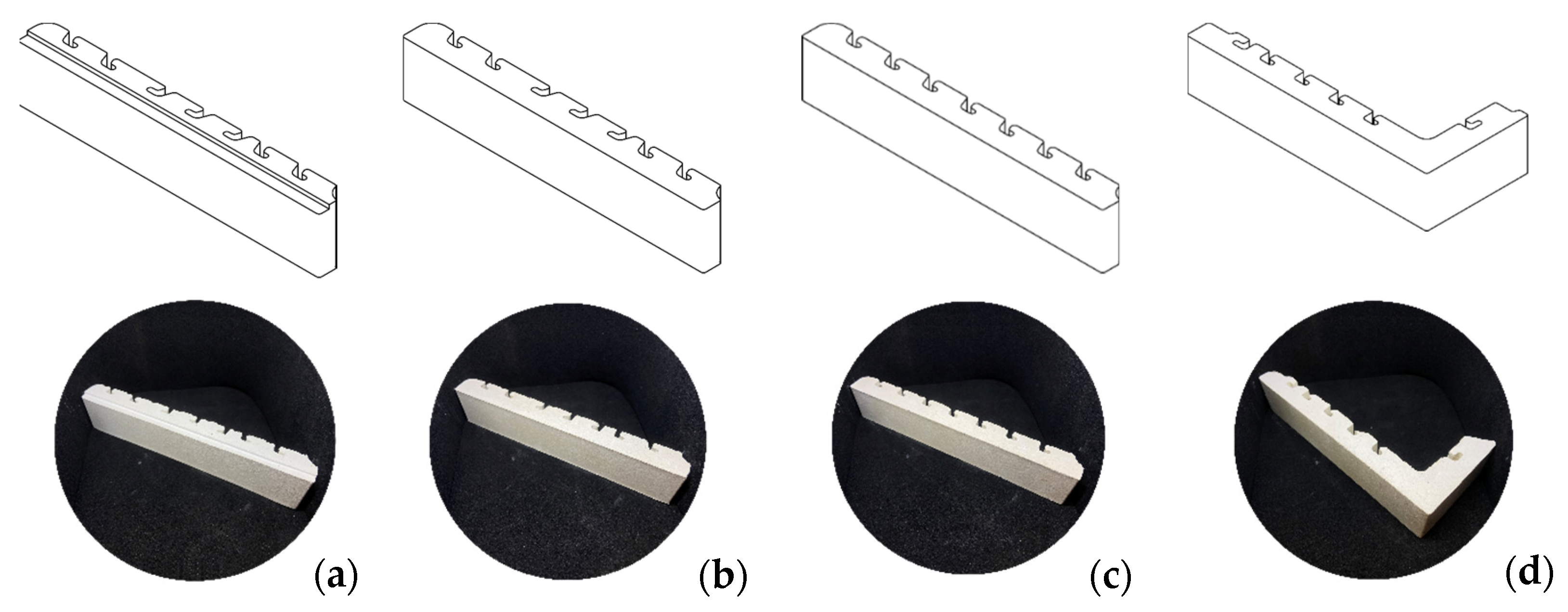
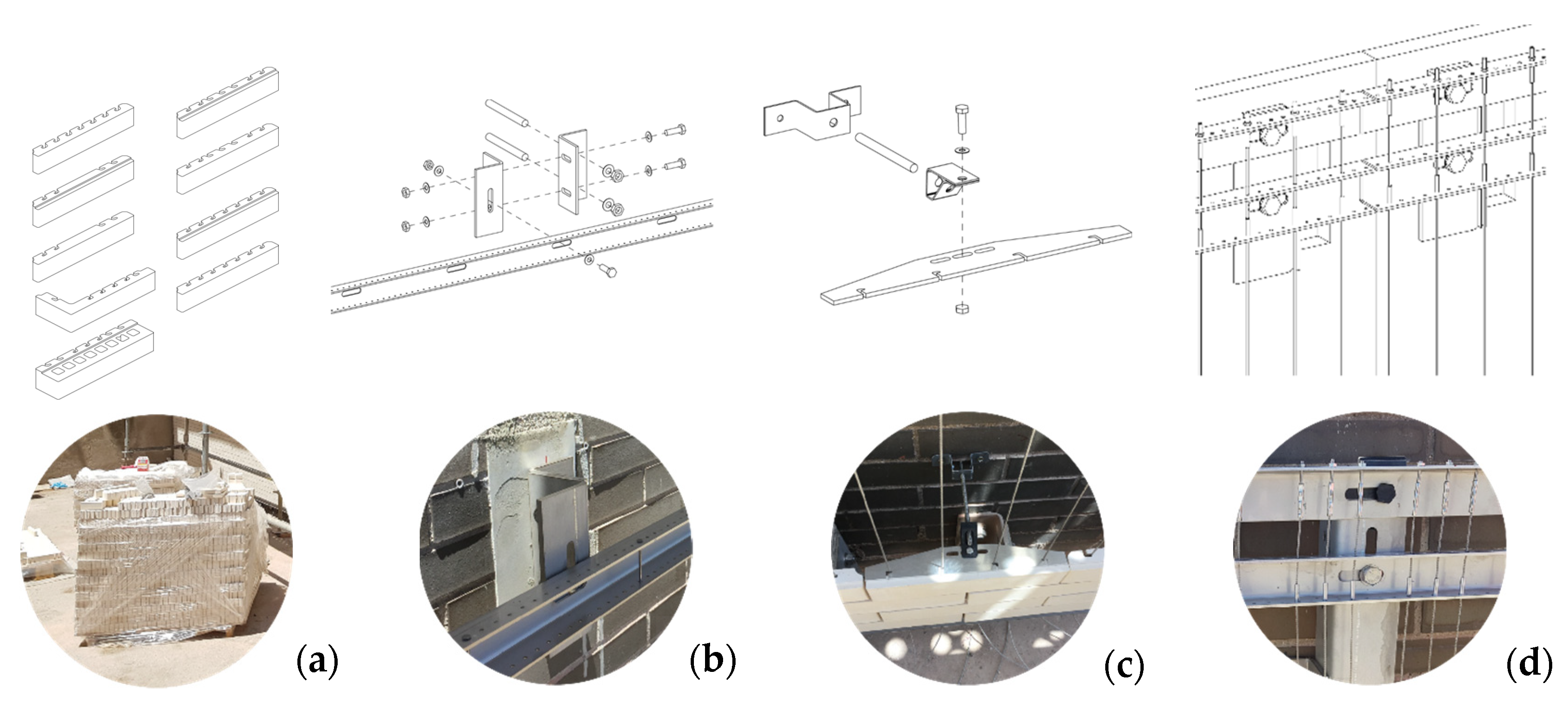
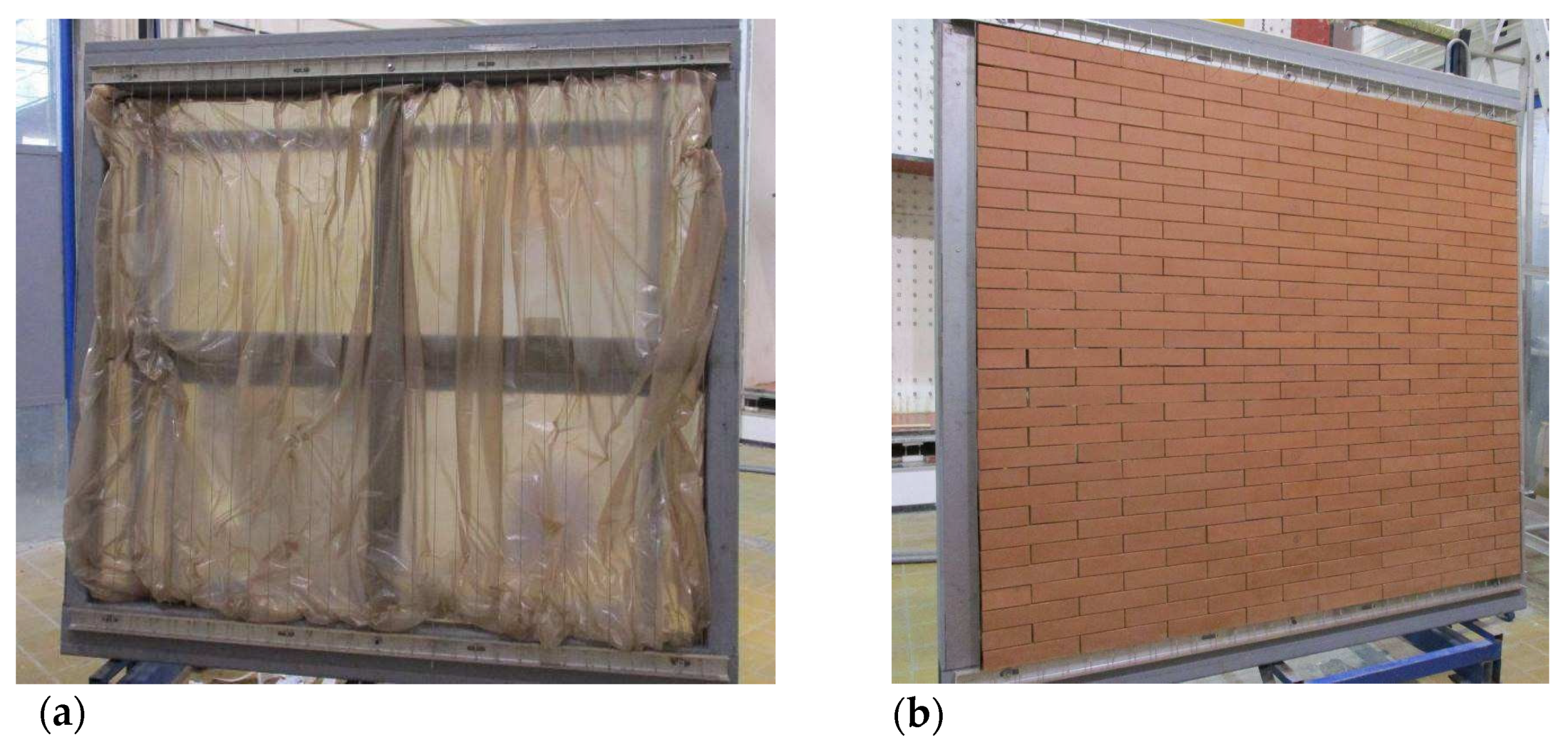
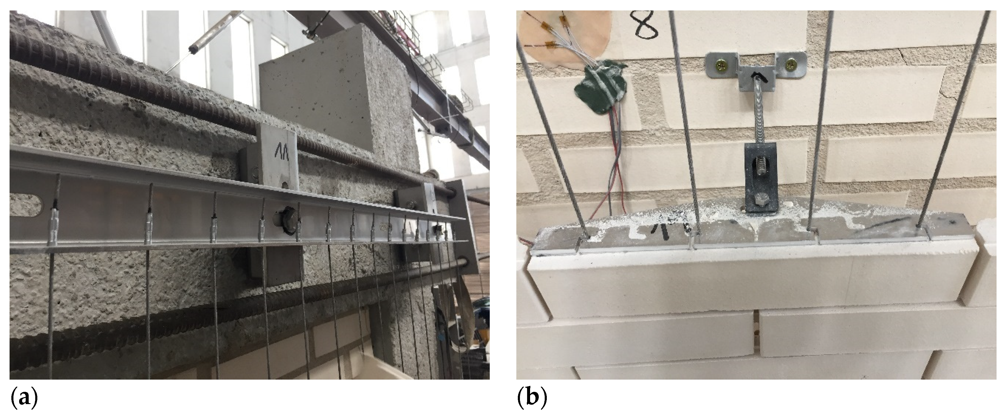
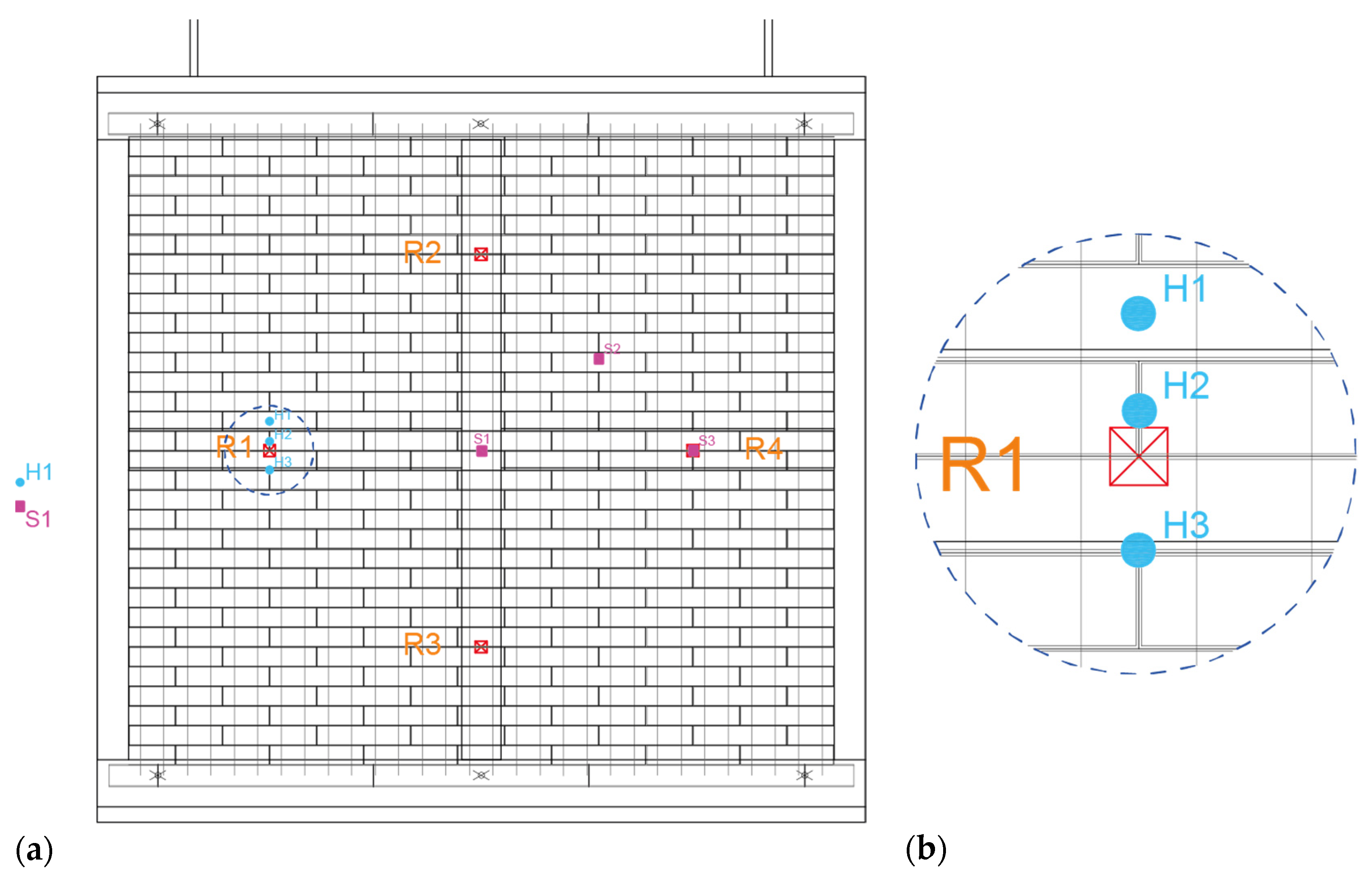
2.3. Experimental Characterization of Materials and System Features

To determine the components’ features that are specifically designed for the system, the different constituents are characterized and tested: ceramic parts, stainless steel metal elements, anchors, etc., in accordance with the applicable regulations, and depending on the specific requirements in each case, considering that, when necessary, the tests are adapted (Table 1). Based on this process and depending on the results obtained, feedback and redesign is carried out based on the detection and resolution of critical points during the characterization of the different elements.
In the test-driven design process, the following phases have been carried out: Phase 1. Adaptation and design of experimental test procedures, according to façade system regulations. Phase 2. Design and manufacture of auxiliary elements for testing. Phase 3. Trial and error tests, according to the dissimilar materials and geometries available for non-ceramic components, and initial evaluation of compliance of each one of them. Phase 4. Testing plan final definition and implementation. Phase 5. Redesign-oriented feedback for the non-ceramic components, based on critical points detected during the execution of tests. This last phase is effective in addressing non-compliance with the stresses to which they are exposed according to regulatory requirements. For instance, based on the results obtained, the type of stranded cable, the cable terminals, and the cable-terminal joints have been redesigned.

2.4. Wind Load Testing

The requirements to cope with the action of wind loads are generally defined, in the Spanish regulation Technical Building Code (Código Técnico de la Edificación, CTE) in the basic document on Structural Safety, Actions in Buildings (CTE-DB-SE-AE) [41], as the application of pressure and suction loads distributed over the surface of the building that respond to the distribution and value of the pressures exerted by the wind on a building and the resulting forces, which depend on the shape and dimensions of the building, the characteristics and permeability of its surface, as well as the direction, intensity, and gustiness of the wind. Although the Spanish regulations establish the requirements in terms of load values that the building, and therefore its external skin, must withstand, they do not specify the methodology to be followed to assess these properties. For this reason, the indications given in the European Technical Approval Guidelines (ETAG) and the European Assessment Documents (EAD) are employed; for the evaluation of wind performance, the indications given in ETAG 034 [42,43] and the EAD 090062-00-0404 [44] are employed.
The sample has been tested as defined in Section 5.4.1.1 of ETAG 034 [42] for wind suction resistance tests for a ventilated façade kit. The test consists of applying wind loads at different pressure steps. Two initial pulses of 300 Pa, one pulse of 500 Pa, one pulse of 1000 Pa and the rest of the steps, increasing the pressure by an additional 200 Pa, are applied. Each step has a duration of at least 10 s (Figure 6). After the application of each load step, the wind pressure is stopped, and a new load cycle is started. During the application of the pressure, the reading of the displacement transducers on the sample and the residual deformation of the displacement transducers 1 min after the end of the pressure step are recorded. Any damage is also noted. The test continues until the deformation produced is irreversible and causes a malfunction of the lining system, or if collapse occurs.

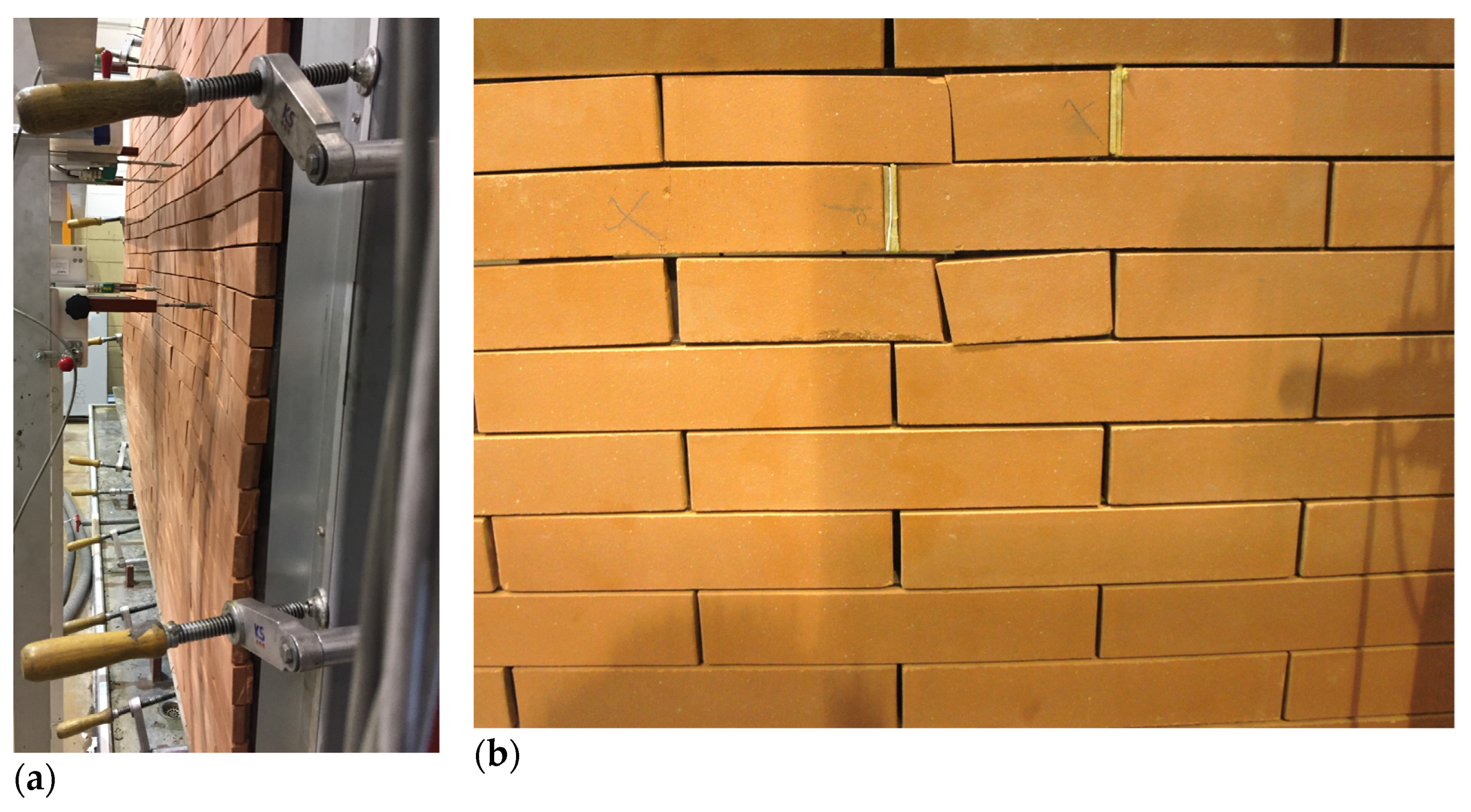
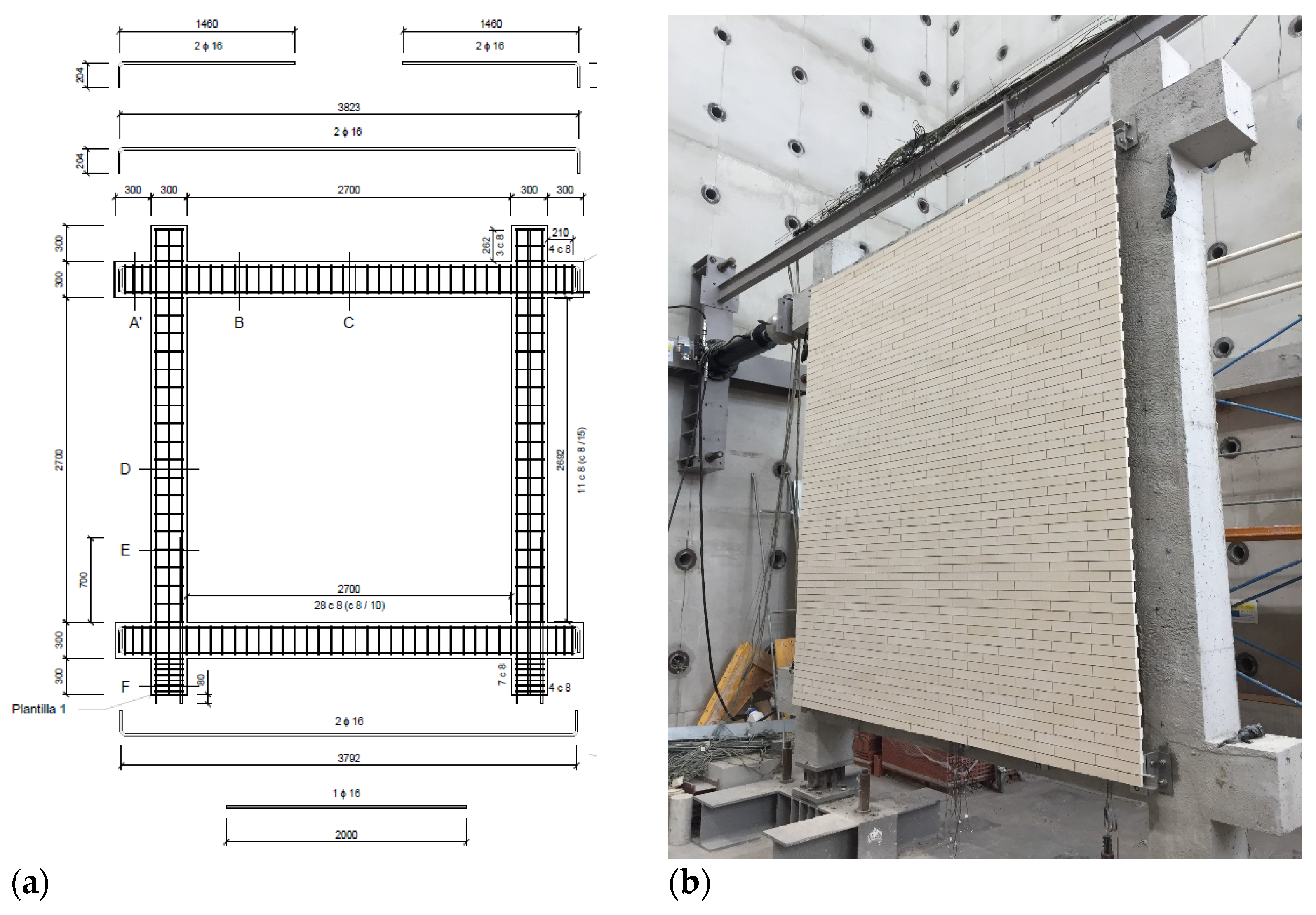
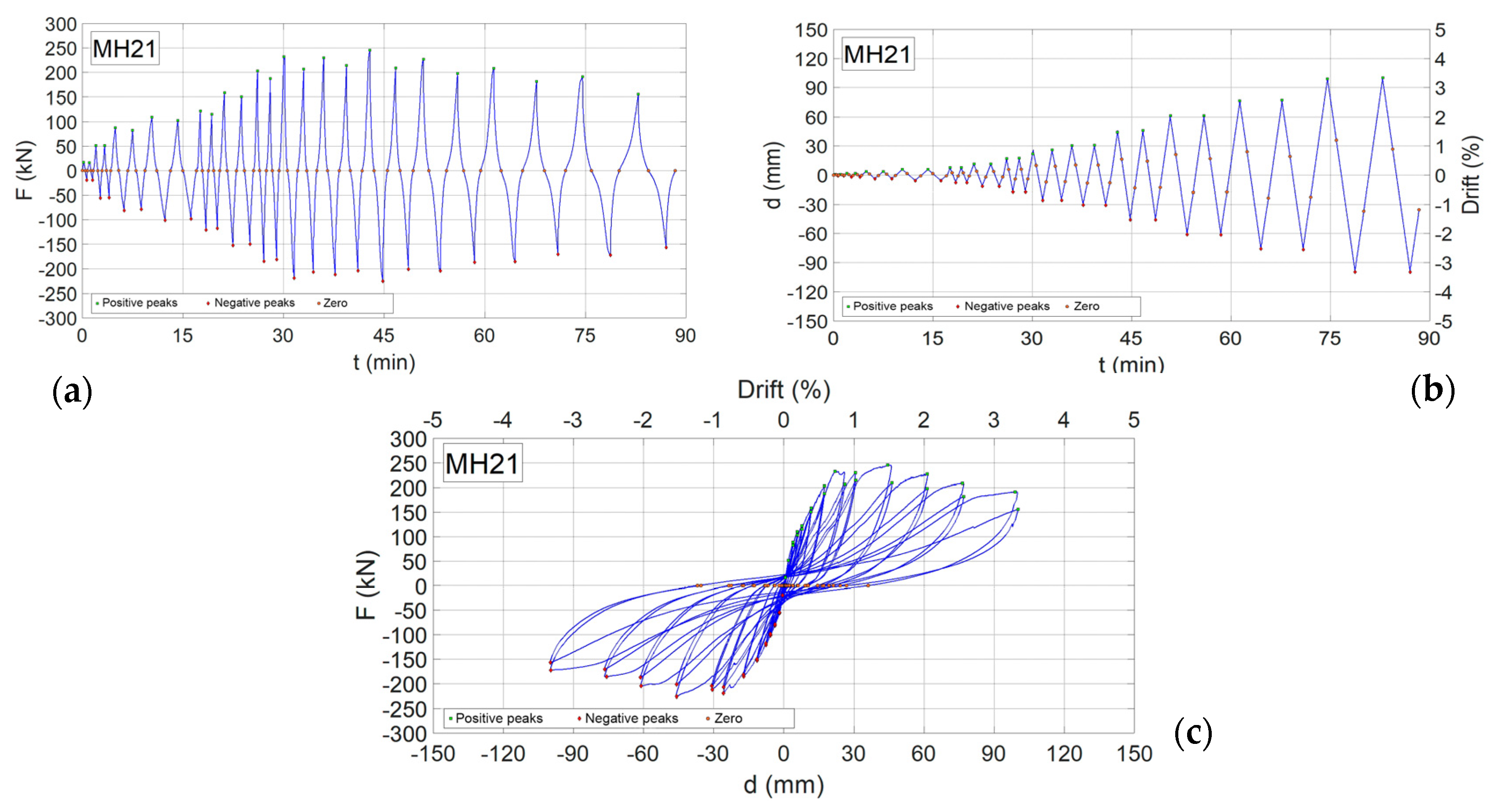
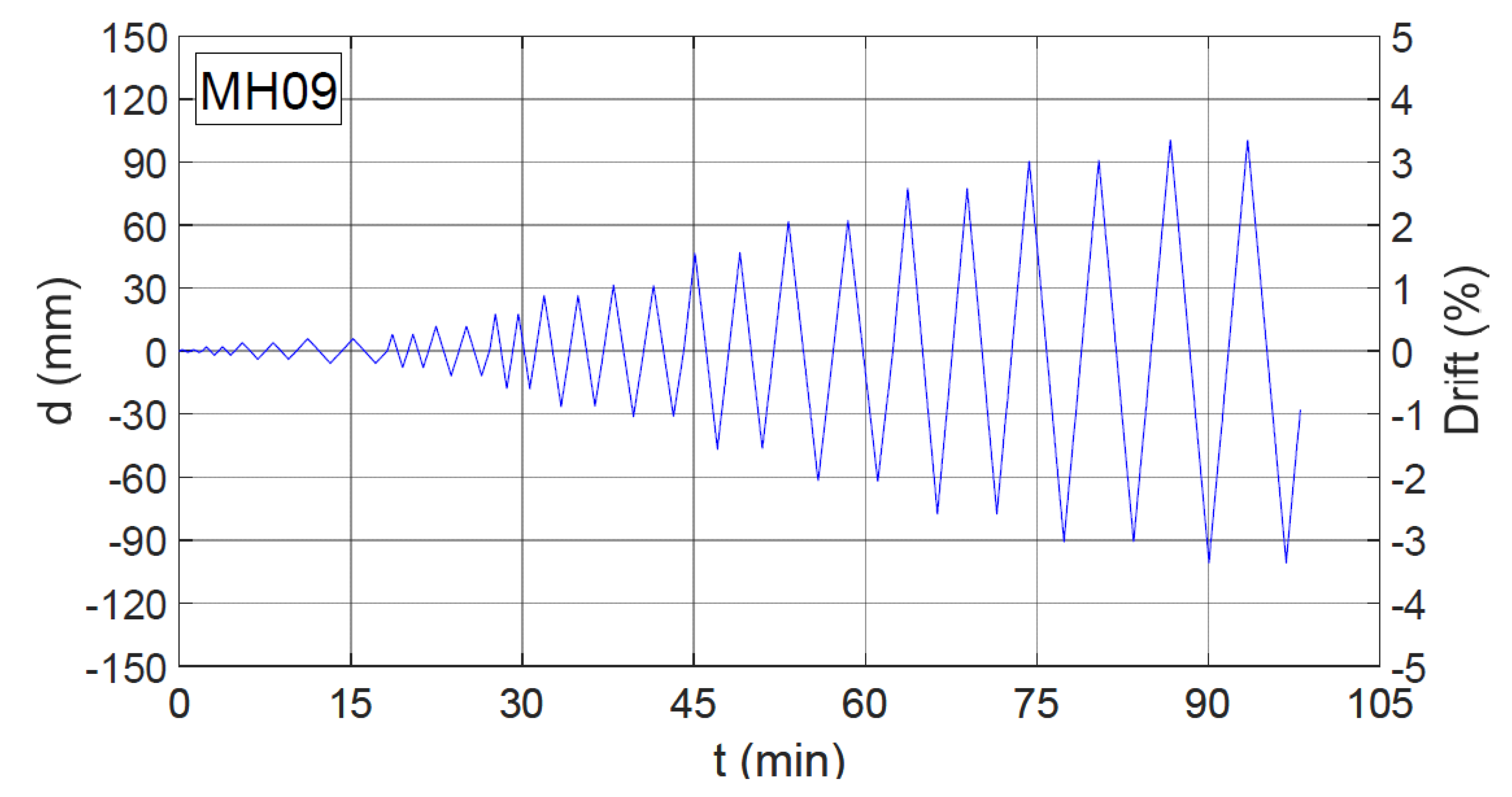
2.5. Earthquake Testing

DSFs and other traditional non-load-bearing cladding systems are construction techniques for covering and finishing building parts that are considered as non-structural elements. This means that they are only considered as gravity loads for structural calculations, although the situation becomes different when analysing the effects of dynamic loads. These elements influence the strength, damping, hysteresis, and deformation of the building [45]. The existing Spanish standard NCSE-02 [46] refers exclusively to claddings, interior partitions, false ceilings, and other elements, such as façade panels, etc.; all of these must be properly bonded to structural elements to avoid the detachment of parts during seismic shaking, especially if the ductility of the construction is assumed to be high or very high. In addition, in transit areas, the fixing of cladding and the anchoring of cladding or other façade elements must be carried out with highly durable materials and using appropriate techniques, to prevent the detachment of parts in the event of an earthquake. Emphasis is placed on the risk derived from the detachment of façade elements due to inadequate fixing, considering as such the exclusive use of chemical joints, indicating that mechanical fixings by means of metallic elements are considered appropriate [41].
It was considered necessary to know the system performance against the earthquake dynamic action, so a test and loading protocol was followed, based on the proposals of FEMA 461 [47] and the study carried out in the article “Experimental study on the response of seismically isolated masonry infilled steel frames during the initial stages of a seismic movement” by Pallarés et al. [45]. A horizontal cyclic load is applied to the upper beam of the portal frame (loading and unloading) which houses the ventilated façade leaf and a rear brickwork cladding, which simulates the conditions against a seismic load in a real situation. The operator that applies the load and thus generates the cycles has a capacity of up to 500 kN and is responsible for increasing the displacements at the head of the gantry by applying an increasing force at each cycle. For more detailed information on the process see Appendix A, Table A3. The main characteristics of the test are defined below:
-
There is a protocol where the monitored quantity is the displacement.
-
Each cycle (cyclic load applied) is composed of two sub-cycles. The first is the so-called noval sub-cycle and is composed of four sections. In the first section, the gantry is pushed to the right until the target displacement is reached in the load cell. In the second section, the gantry is pulled to the left until it returns to the initial position. In the third section, the gantry continues to be pulled to the left until the same displacement as the first section is reached in the load cell, but in the opposite direction. Finally, in the fourth section, the gantry is pushed back to the initial position. For more information see Appendix A, Figure A1.
-
In the second sub-cycle, known as the reloading sub-cycle, the same operations are repeated as in the first noval sub-cycle, with the same target displacement.

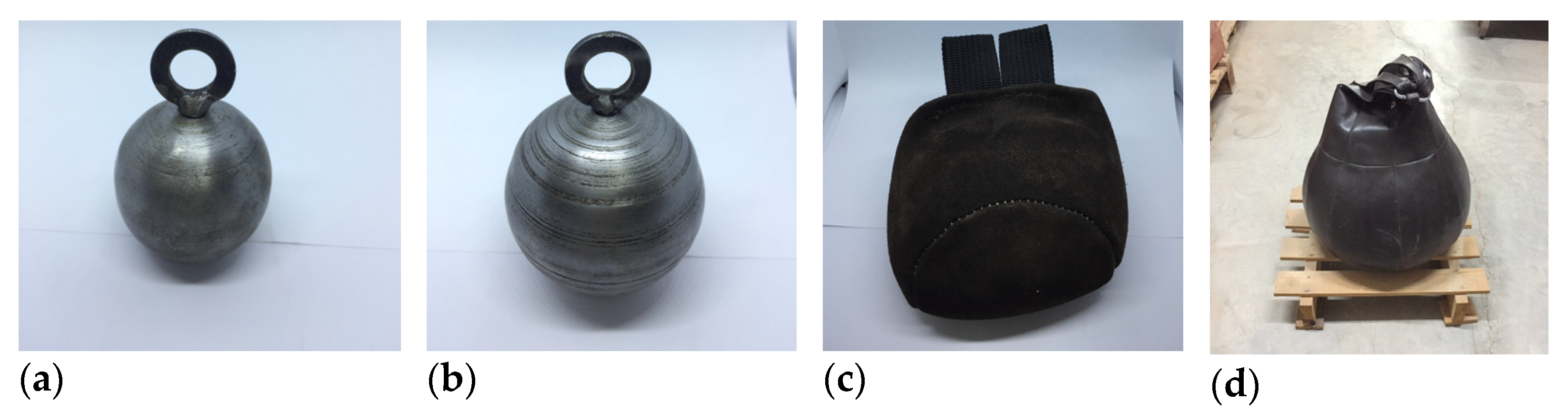
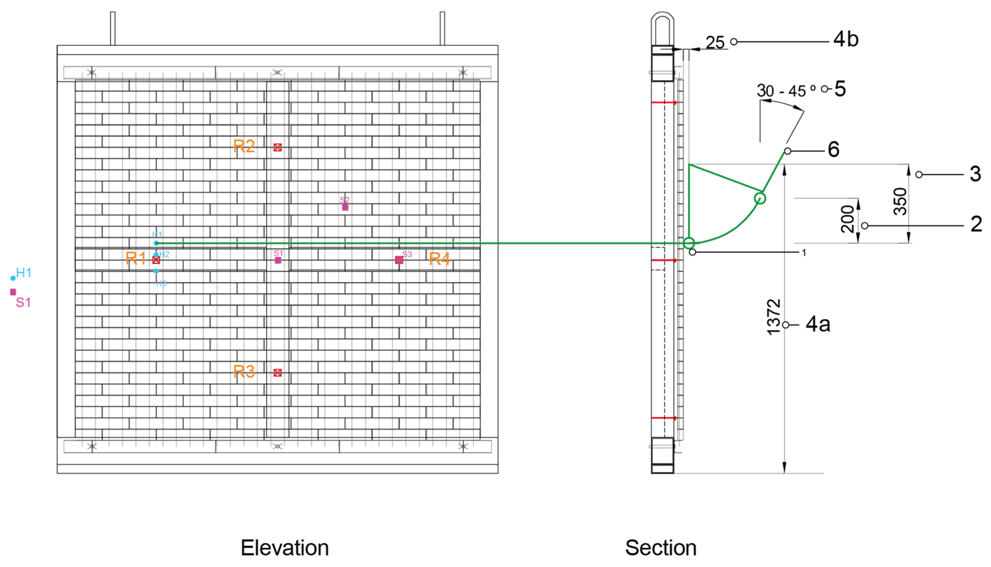
2.6. Safety in Use: Exterior Impact Testing

The Spanish regulatory framework follows the requirements established in the Technical Building Code, which does not establish a minimum performance that ventilated façade systems must guarantee, in relation to their resistance to external impacts [41]. The regulation is the same for internal partitioning systems, which are also assessed against impact situations and eccentric vertical loads to ensure safety in use, although there are no national regulations in this respect [48]. The European standard establishes, through the Construction Products Regulation no. 305/2011 (CPR), that systems can obtain the CE mark if they are assessed according to the European Technical Approval Guidelines (ETAG) or through the European Assessment Documents (EAD) [25]. In the case of impact assessment, we used ETAG 034 [42,43], later converted into EAD 090062-00-0404 [44].
Tests are based on the application of an impact energy on the façade sheet. The energy transmission is undertaken using both a hard body, and a soft body, which resemble the impact of a small but hard object (e.g., hail or stones) and the impact of a larger but soft object (e.g., a falling person). Thus, the façade system performance is evaluated and classified, according to a category of use, depending on the joules of energy supported. The category of use establishes the locations where the evaluated system could be placed, depending on whether they are accessible, heavily used, public, private, high, etc. For more detailed information, see Appendix A, Table A4.
In addition, following the ITeC criteria, a sub-classification is added that allows façades to be categorized as easily replaceable or repairable products, if they can maintain their position on the façade when they have broken due to the effect of an impact, without allowing them to fall after breakage [49]. In this way, the energy values of impacts on the façade are reduced, allowing products that are, in principle, more fragile to access better categories of use. For more detailed information see Appendix A, Table A5.

3. Results and Discussion

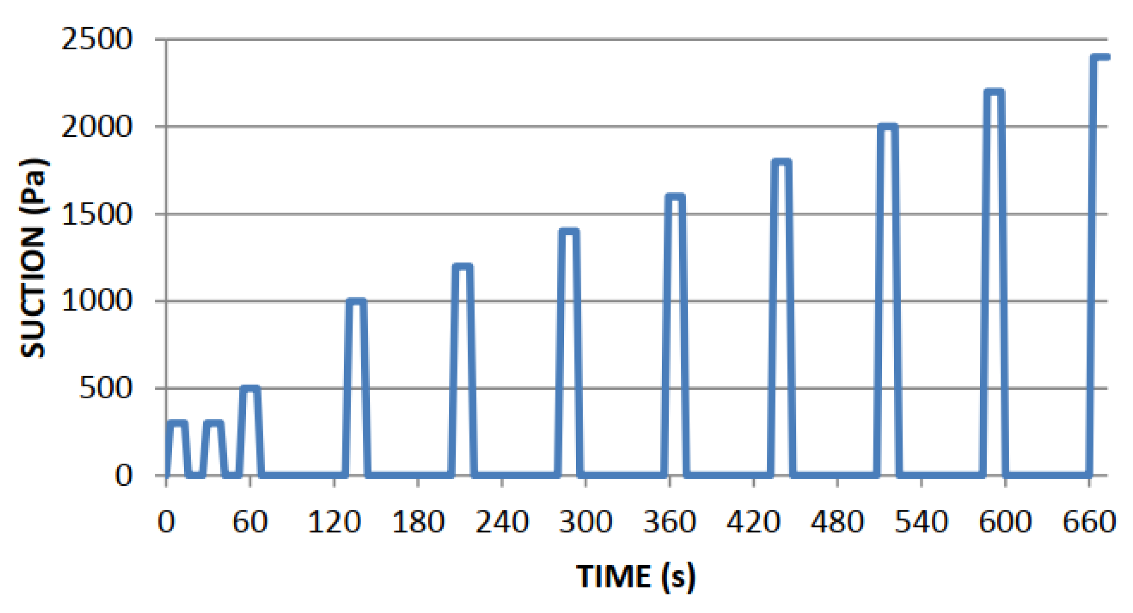
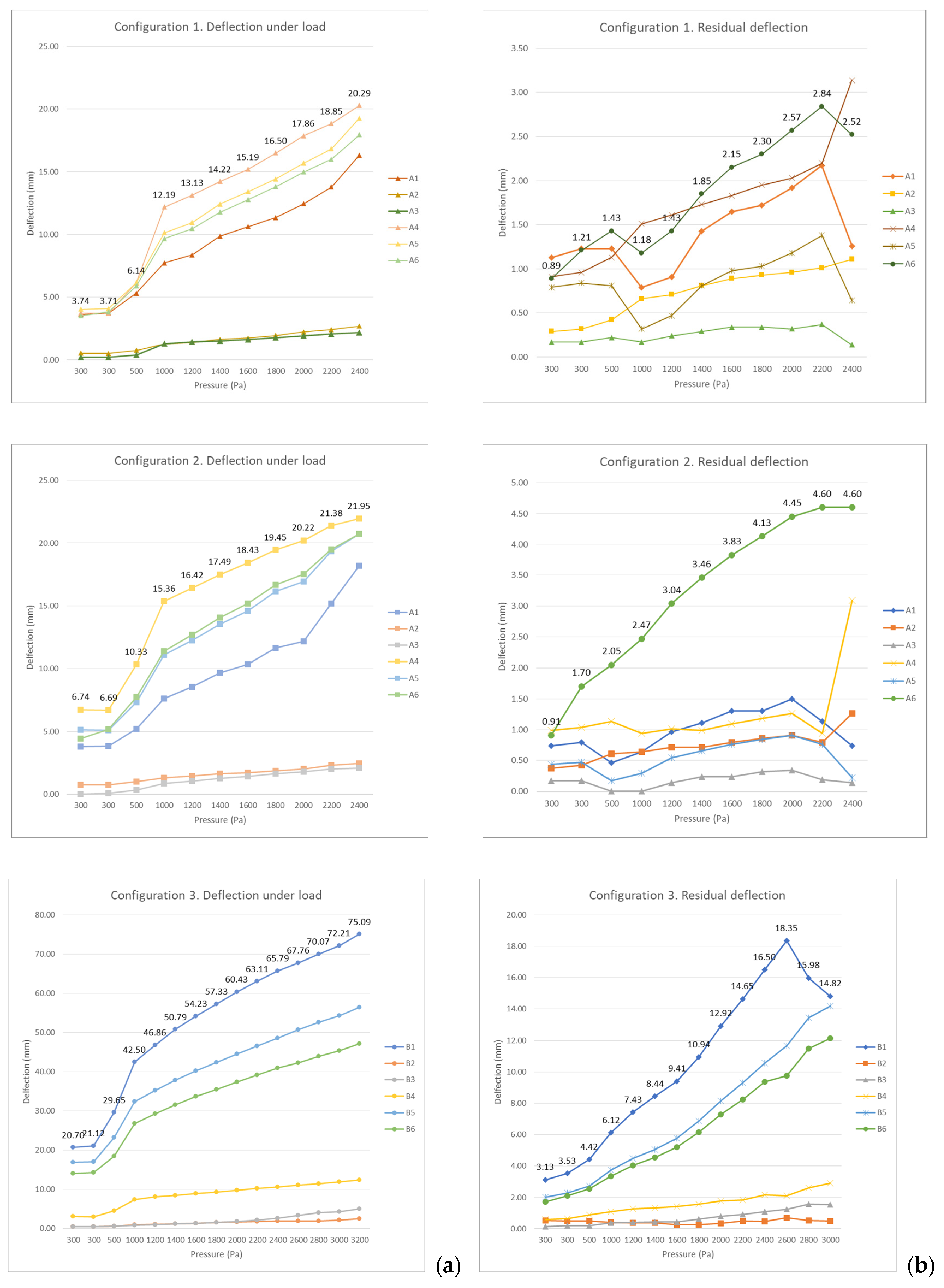
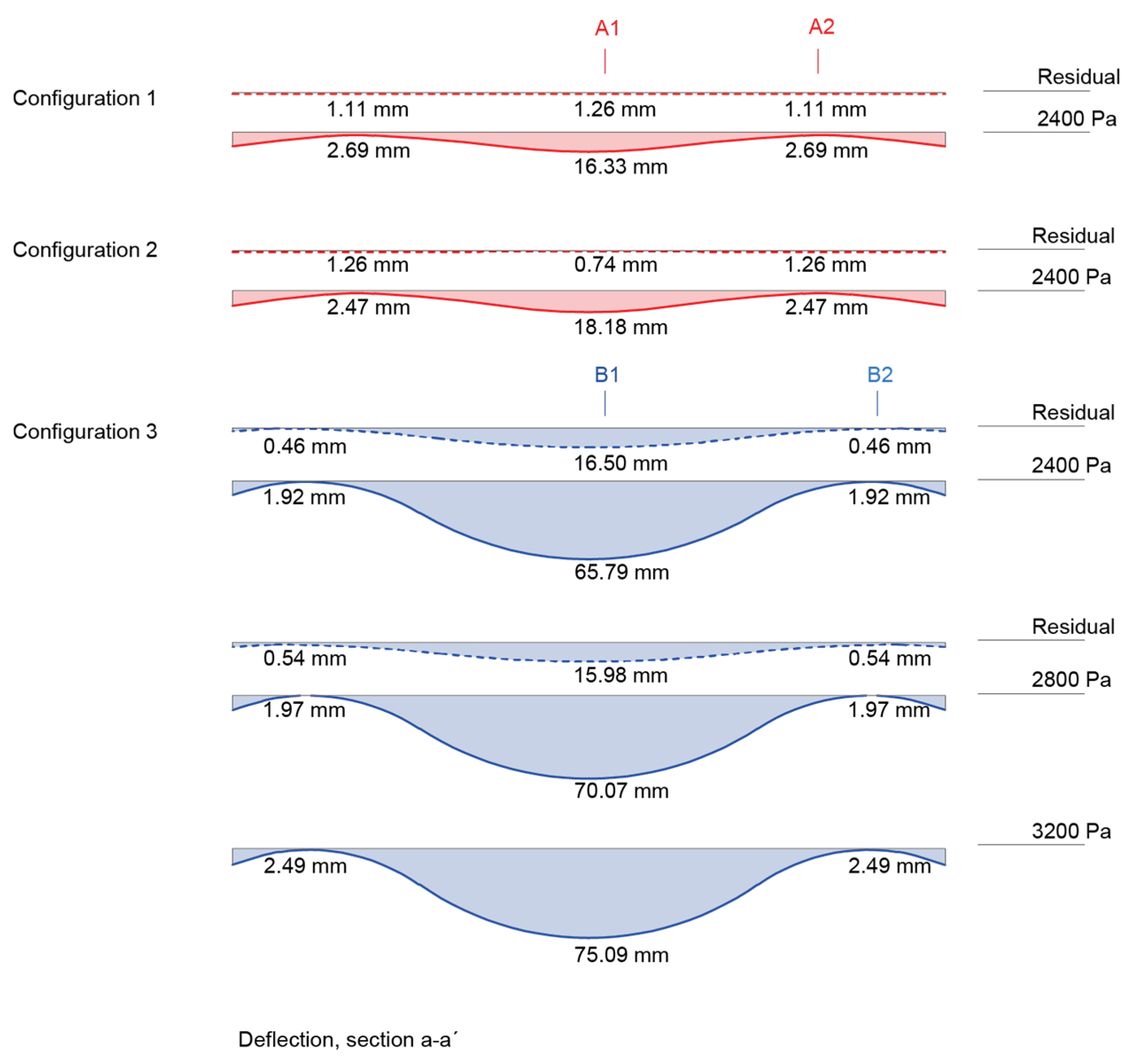
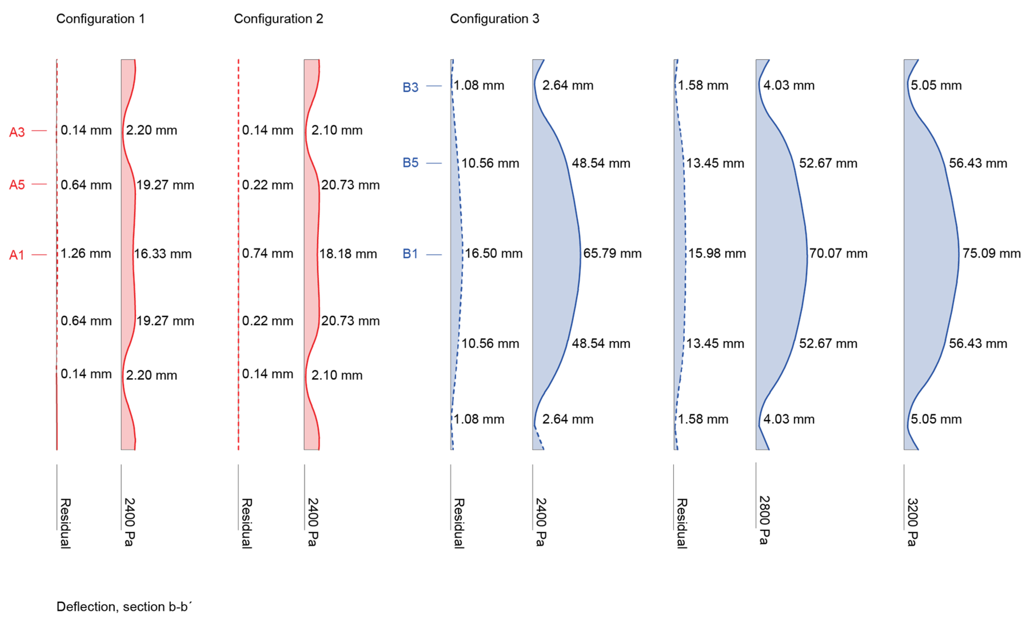
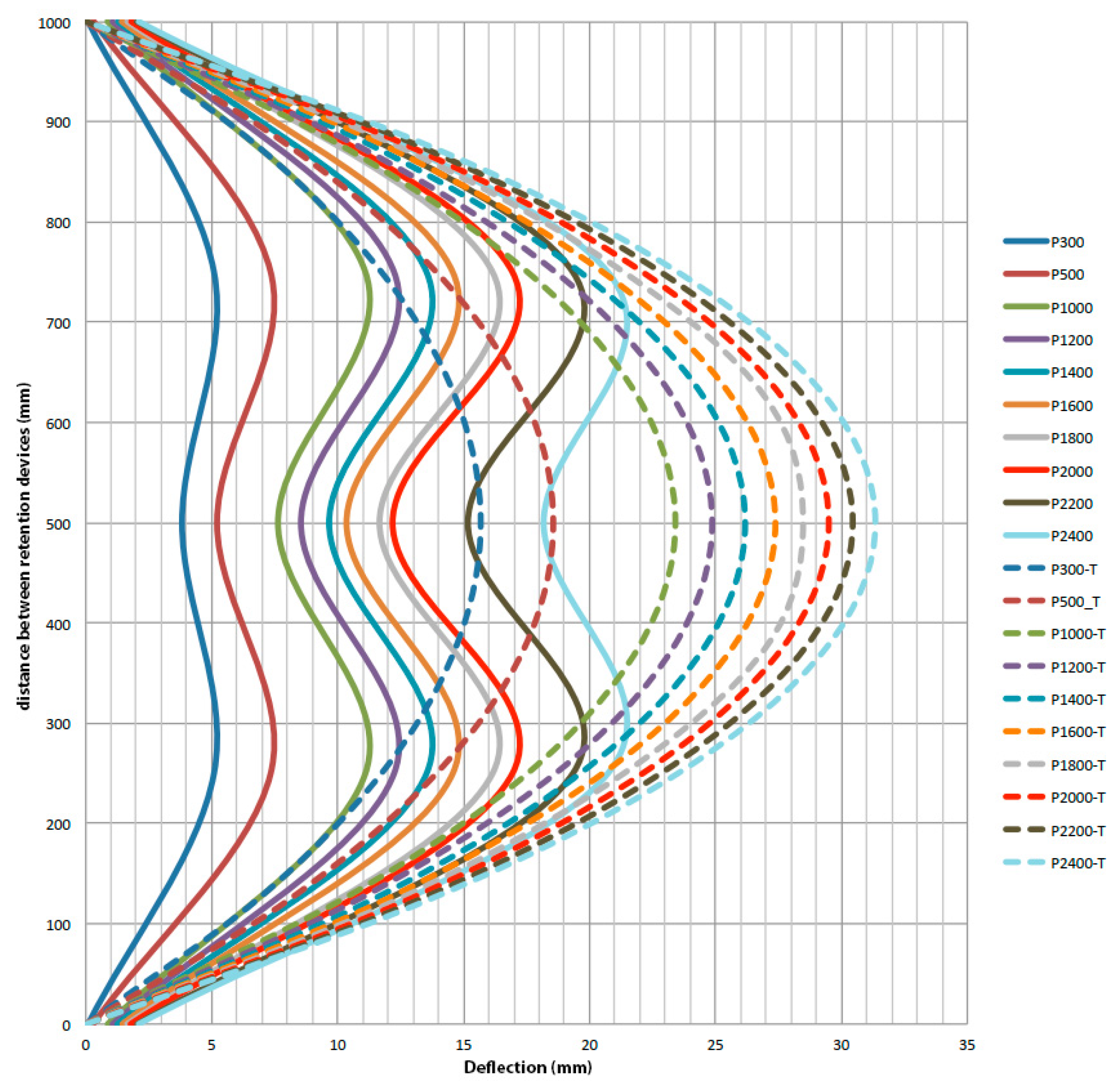
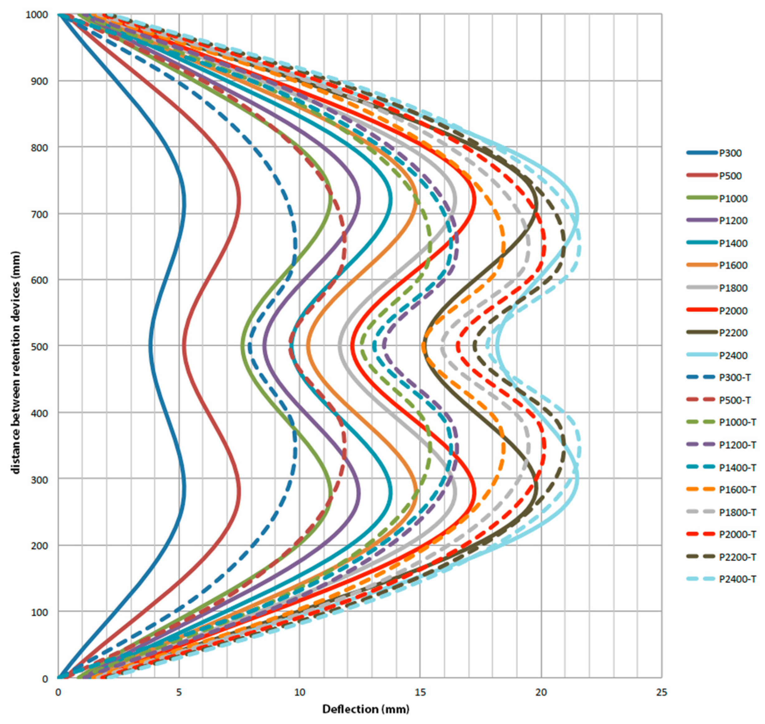
3.1. Wind Load Assessment

Once the individual characteristics of each of the components have been evaluated, the performance under wind loads is studied, especially since they could compromise the functioning of the façade system. An experimental laboratory test was carried out, on a suitably-sized scale, to test different configuration cases. Once the experimental test has been carried out, several simulations are performed using finite elements (FE) to check and validate the interaction of the ceramic pieces with the vertical metal wiring, characteristic of the system when it receives wind loads, as well as the behaviour of the point anchors that are distributed along the surface of the façade, known as retaining devices (Figure 5c), whose purpose is to support these actions on the surface of the façade.
This case study is designated as a ventilated façade ceramic exterior cladding kit according to ETAG 034 [42], with dimensions of 1820 × 1720 mm2 (W × H), with a ceramic surface area of 3.13 m2 in a normal arrangement (60 mm spacing between cables) for the supporting devices. To simulate real on-site installation conditions, the samples are installed on a steel tube perimeter support frame with vertical profiles of 100 × 80 × 6 mm and shaped top and bottom profiles of 100 × 120 × 4 mm, welded on a profile of 100 × 40 × 4 mm. Two welded steel tube uprights, a horizontal and a vertical cross member of 100 × 60 × 6 mm, are added, to simulate the anchoring arrangement on site, as shown in Figure 7.
The specimen is installed in a K. Schulten Fenstertechnik model KS 4040/650 PC with manual clamping cylinders [50]. To improve the air tightness of the specimen, so that the appropriate pressure can be generated in the test rig, the inner side is covered with a non-air-permeable foil, leaving sufficient clearance so that it cannot influence the specimen performance during the test. In this way, the specimen becomes airtight, preventing leakage between the joints of the ceramic pieces. The lateral space between the sample and the supporting structure is closed with two “L” profiles screwed to the structure (Figure 8).
To record the displacements during test, linear measurement transducers are implemented. Two different displays are used, one for configurations 1 and 2 and a second for configuration 3. This is due to the varying distance between the wind retaining elements and the different position of the measuring transducers. One of them in the middle of the horizontal between retaining devices (A1 and B1); a second one on a retaining device forming the previous horizontal (A2 and B2); a third one on half of the vertical joining a retaining device (A5 and B5); a fourth one on a retention device forming the previous vertical (A3 and B3); a fifth one on the crossing between vertical and horizontal traced (A4 and B4) and, finally, a sixth one on the half of the diagonal joining (Figure 9).
For configurations 1 and 2, similar results have been obtained in terms of displacement under load and residual deformation when the load is no longer applied. The displacement produced in these cases is small, around 20 mm, and once load ceases, the pieces recover their original position. In the case of configuration 3, higher values of displacements are achieved, since the proposed configuration of retention devices allows for a greater displacement of the façade skin: around 70 mm for 3200 Pa of pressure (Figure 10).
Following the criteria described for the sensors’ display, a complete sector of the sample is accurately monitored and, since the pressure is assumed to be homogeneous and fully symmetric on the vertical and horizontal axes, it is possible to know the values produced on the rest of the surface. Knowing these values, it is possible to represent the most unfavourable situations of each of the configurations and to obtain, by means of a horizontal section (Figure 11) and a vertical section (Figure 12), the deformations produced during the test on the ceramic skin.
The results obtained during the execution of the tests are considered satisfactory, with the sample reaching 1800 Pa of pressure (1.8 kN/m2) with no defects in either the ceramic or metallic elements. During the execution of the test for configuration 1, the breakage of ceramic pieces near the retaining devices occurred. In the repetition for configuration 2, breakages occur in one piece at 1800 Pa (1.8 kN/m2) and in three pieces at 2200 Pa (2.2 kN/m2), although the test continues up to 2400 Pa (2.4 kN/m2), matching the test for configuration 1. During the execution of configuration 3, the breakage of the first ceramic pieces occurs at 2800 Pa (2.8 kN/m2) and the test continues up to 3200 Pa (3.2 kN/m2), the upper limit of the test chamber. The ceramic skin has showed flexibility as expected, with breakages occurring in the configurations with a greater number of retention devices and therefore less flexibility. It should be noted that, although there was breakage of parts, there was no detachment from the plane of the façade, as they remain locked with the metal cables (Figure 13). For more detailed information see Appendix A, Table A6 and Table A7.
Prior to carrying out the tests, a theoretical model was developed to determine the façade cabling performance, with the main objectives of understanding its functioning and developing a calculation abacus of possible situations in which the system could be installed, depending on the location of the target building. In Figure 14, the curves in the graph represent the deformation of a cable for different wind pressures. The comparison between the experimental deformation of the central cable (dashed lines) and the deformation obtained by theoretical calculation (continuous lines), considering a separation between retaining anchors of 1 m, is shown.
The resulting conclusion is that the theoretical model does not reproduce the coercion generated by the ceramic pieces and, therefore, reduces the deformation at the intermediate point, as does occur in the execution of the test, according to the data obtained. The theoretical deformations produced greater deformations than the experimental ones, thus allowing the design to remain on the safe side.
However, although these results have a margin of security, the theoretical model was adjusted by fitting the results obtained in different cable configurations with the most unfavourable values from the experimental tests. The result is shown in Figure 15, where the theoretical model reproduces the experimental results more adequately. In any case, the theoretical model continues to provide higher values, compared to the experiment, and therefore offers more reliable values.

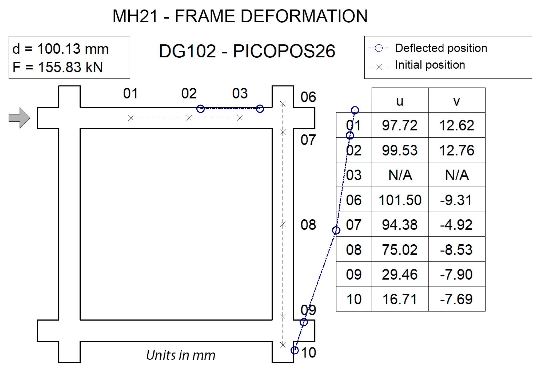
3.2. Earthquake Response Assessment

The DSF case study performance assessment during an earthquake event was carried out experimentally as part of the façade characterization tests, on a full-scale test specimen built in the laboratory. The objective consisted of testing the performance of a ventilated façade of the system, built on a concrete portal frame filled with traditional brick masonry elements, similar to the most common construction types in Spain [51].
The sample built for the test represents an intermediate portico of a building and it is constituted on the basis of three essential parts: firstly, a concrete frame, responsible for receiving the cyclic thrusts and tractions, as well as supporting the rest of the elements; secondly, a pre-existing enclosure, consisting of a traditional façade with a double brick façade and hollow bricks cladding, with both brick walls free of seismic insulation systems (Figure 16); and thirdly, an outer sheet of the ventilated façade system, consisting of small ceramic elements and vertical cable mesh in its usual configuration, as shown in Figure 2.
The frame is a reinforced concrete portal frame consisting of two beams and two 30 × 30 cm square columns, 3 m high and 3 m wide. The frame is fixed to the foundation slab by means of two joints at the lower ends of the columns. Each of these elements is reinforced both longitudinally and transversely, to withstand the stresses simulated during the test. The so-called pre-existing enclosure is a 2.7 × 2.7 m2 double-brick wall, confined within the reinforced concrete frame. It simulates the stiffening performance of vertical separations within multi-story arcade structures. It is composed of several layers: a 11.5 cm white clinker facing brick layer with 1 cm thick M7.5 mortar joints; a 1 cm thick cement mortar filling on the inside face of the facing brick leaf; a 3 cm unventilated air space; and a 7 cm double hollow brick layer (Figure 16).
The third part of the sample installation corresponds to the ventilated façade sheet, executed dry and with stainless steel wire mesh corresponding to the system developed, with a total of 64 rows with 12 platelets for each one (Figure 17).
Since, during the test execution, unexpected events usually occur, that are not visually controlled in the hidden parts of the specimen, the sensors’ locations are carefully planned, to check the state of the concrete frame and the pre-existing brickwork leaves. These walls are also partially hidden behind the ventilated façade panel on the outside face. For more detailed information, see Appendix A, Table A2. The whole loading protocol establishes 15 cycles of cyclic loading (Table A1); however, if during the development of the test there are evident signs of failure or collapse of the sample, the procedure is stopped, and the test is terminated. In this case, the test was stopped at the completion of cycle number 13, after the collapse of the hollow brick inner leaf and after having followed the standard protocol cycles; for more detailed information, see Appendix A, Table A3. The graphical display of these cycles is showed in Figure 18.
As already specified, the test process is stopped at iteration number 13 due to the existence of considerable damage in parts 1 and 2 of the sample, i.e., in the double brick sheet, similar to a traditional façade. The magnitude of the damage can be seen in Figure 19. The proportions of these damages prevent the continuation of the standard progress of the cycles, so it was decided that the procedure would be stopped, and the test would be concluded.
During the execution of the test, the ventilated sheet performance consists of the displacement of the plane of the sample from left to right, following the movement of the concrete frame according to the moment of the cycle in which it is found. As the system has a certain degree of freedom in the face of loads, the ceramic tiles adapt to the new positions imposed by the movement of each of the cycles, and there are hardly any small defects visible to the naked eye.
The damage assessment at the ventilated façade level covers both the verification of ceramic and non-ceramic elements. This distinction is made because ceramic elements are understood as a non-structural cladding, in which the replacement of affected parts after a hypothetical earthquake is at the discretion of the risk that may exist against the detachment of small debris, but not because the overall stability is compromised, as it would be in the case of non-ceramic elements. The damage to the ceramic skin is limited to small flaws, or the chipping or breakage of pieces that appear as cracks, but without any detachment of rubble at any time (Figure 20). In the non-ceramic elements, it has been checked that there is no appreciable damage by visual inspection, paying special attention to the position of each element at the beginning and end of the test, with no damage to the support device or the wind retention device (Figure 21).
As key points of the earthquake test assessment on the ventilated façade panel, the following conclusions can be stated: first, damages derived from the action of the earthquake on the traditional walls are produced, as well as detachments in both brick walls and total collapse in the interior cladding leaf; second, the concrete frame, reproducing an intermediate floor, is fatigued and cracked, thus reducing its resistance capacity and its useful life (Figure 22); third, the cladding executed with the ventilated façade system is complete once the test has been concluded, with only small cracks that are not very noticeable in most cases and can be easily repaired by replacing parts; and fourth, in relation to the amount of surface area covered, the percentage of cracked pieces is very low and no pieces of ceramic tile or falling debris originating in the ventilated façade have fallen off.

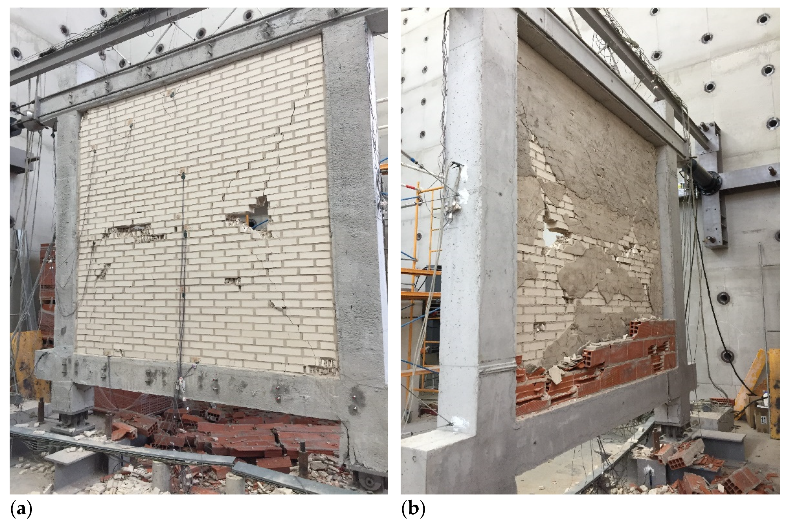
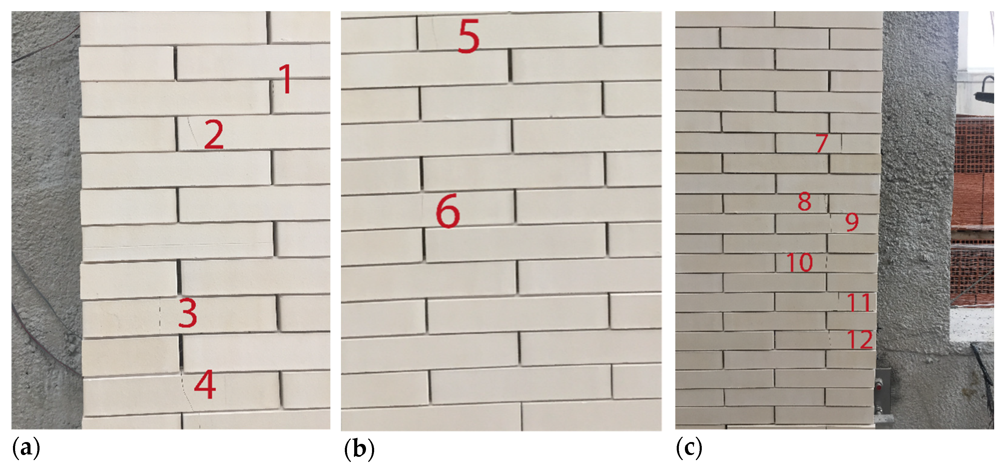
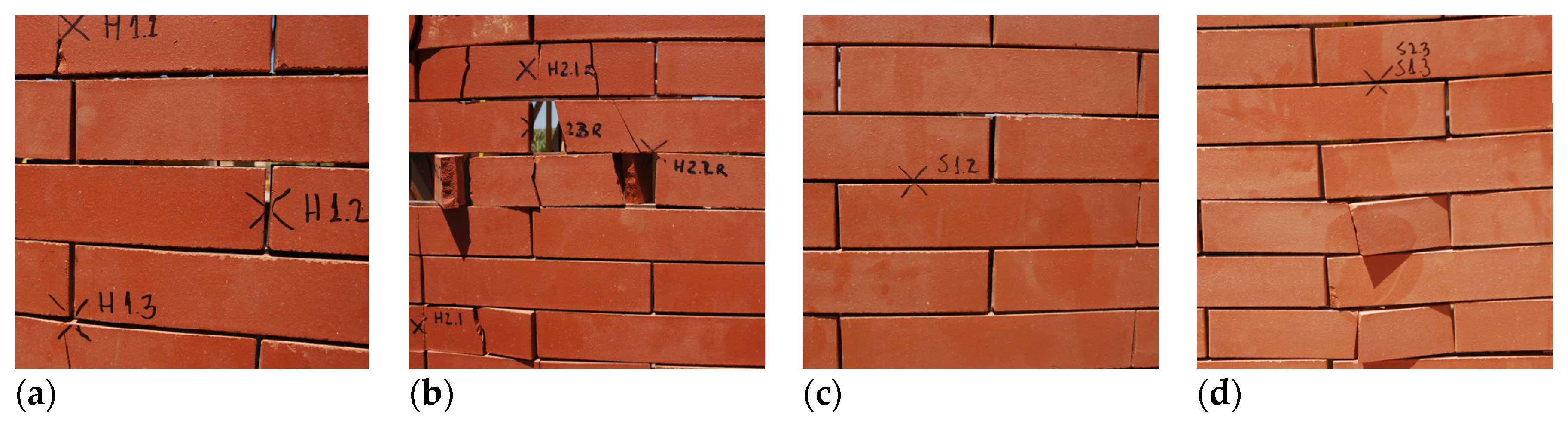
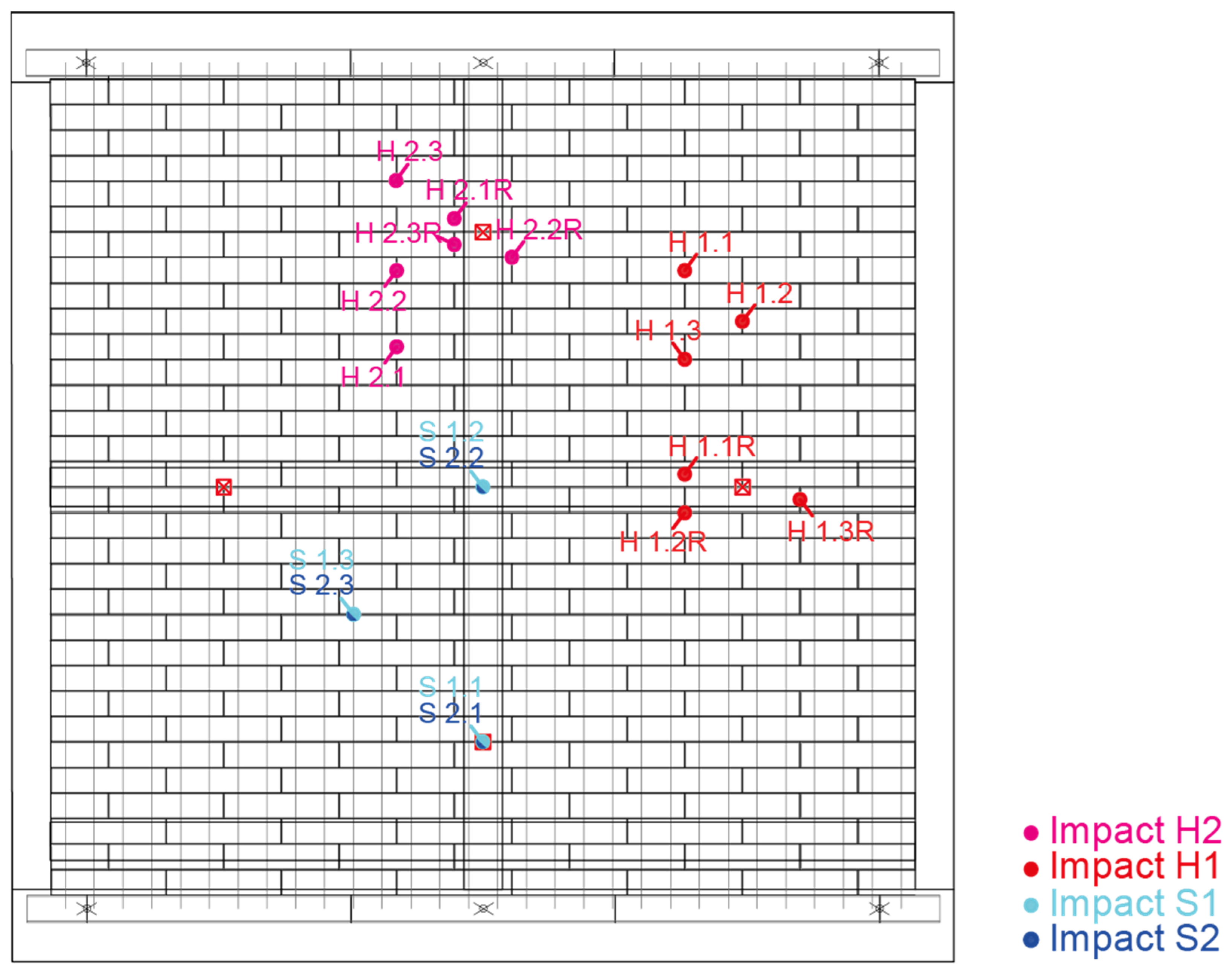
3.3. Impact Assessment

A sample, with the dimensions of 1820 × 1720 mm2 (width × height), was used for the impact test, using the steel frame manufactured for the wind test and applying the same standard arrangement of ceramic tiles, with wire spacing every 60 mm (Figure 5). The devices used as impact means are two steel balls of 0.5 kg and 1 kg, as hard bodies, and two bags of 3 kg and 50 kg, as soft bodies (Figure 23).
The sample was tested, as defined in Section 5.4.4 of ETAG 034 [42], as well as in the ITeC criteria [49] for ventilated façade systems that allow replacement. The criterion used is to first perform all hard body impacts by replacing the impacted parts with untested parts, before moving on to the next loading step. The hard body impacts are carried out according to the following criterion: the first impact is in a centred position on a ceramic piece, the second impact is on the vertical between two pieces, and the third impact is at a point where three pieces meet, without using previously impacted ceramic pieces in each of the repetitions. For the soft body impacts, the criterion, of carrying out the different collisions both in the areas close to the retainers and in those further away, is followed, with the aim of testing and comparing the sample performance in different confinement conditions, both cable and ceramic tiles (Figure 24). The procedure for handling the impact bodies is shown in Figure 25.
Following the above criteria, the impacts are performed by energy steps and with the impact of the hard body on the ceramic skin (Figure 26 and Figure 27): the first impact performed H1, 1 J with a 0.5 kg hard body, a drop height of 0.20 m, and three repetitions. It causes cracks in the ceramic elements that can be seen on the back of the piece, but no pieces are detached (Figure 26a,b). With the same energy, a repetition of the H1R impacts is carried out in other locations, with the same result. The second impact, H2, is 3 J with a hard body of 0.5 kg, a drop height of 0.61 m and three repetitions. It causes cracks with detachment and twisting of the impacted ceramic elements (Figure 26c,d). For the same impact energy, H2R, a repetition of three impacts is carried out, with the same result. The results obtained for the impacts with the 0.5 kg hard body led to a decision not to continue at higher energies, as the 3 J impacts determined that the test for this body should be stopped. The test continues with the soft body impact: the first impact performed S1, 10 J with a 3 kg soft body, a drop height of 0.34 m, and three repetitions. There is no damage to the ceramic elements (Figure 26c). The second impact, S2, is 60 J with a 3 kg soft body, a drop height of 2.04 m, and three repetitions. It produces breaks in the ceramic pieces, allowing, in some cases, the cracked elements to rotate on the braided cable. No detachments occur (Figure 26d).
The analysis of the results of the tests carried out to determine the safety of use against external impact shows that the ventilated façade system withstands soft-body impacts without deterioration, which allows a Category IV classification as prescribed in Tests based on ETAG 034 [42,43]. On the other hand, the impacts carried out using a hard body indicate the fragility of the ceramic pieces against this type of impact. However, as it is a system in which the replacement of pieces is simple, and as there is no detachment of rubble as it is confined in the mesh, the system could be used in Category IV. This category allows the system to be suitable for use as façade cladding outside the reach of the ground level, not allowing its use on plinths, ground floors in front of public spaces and similar situations.

3.4. Discussion Overview

The following discussion overview presents a step-by-step and cross-sectional analysis of the results from a series of tests conducted on a full-scale prototype of a cable-suspended DSF. These tests were designed to evaluate the façade’s performance under different load conditions, including wind loads, seismic loads, and impact loads. The objective was to gain insights into the structural behaviour of this innovative façade system under realistic load scenarios, thereby contributing to the ongoing research in this field.
In the present research, in addition to the characterisation of individual components, experimental characterisation and testing of the construction system was conducted to verify its performance. A summary of the results of these tests is shown in Table 2 below, which contains, a priori, tests of wind pressure and suction, impact, and seismic behaviour. Once the experimental data have been obtained, the process proceeds to feedback on and the redesign of elements if necessary, following the scheme foreseen in the design and characterisation of individual components already described.
From the overall analysis of the results, it is determined that the use of flexible ceramic systems in DSFs can be a suitable alternative to rigid ventilated façade solutions, even under stressful wind, impact, or seismic conditions, that test the stability of the constituent elements of the ceramic sheet. In the full-scale tests, the appropriate strength and stability of the metal components were assessed, and even though some of the ceramic tiles were damaged or broken, most of the tested prototype coped adequately with the test’s cycles. If the proposed system is compared with conventional ventilated façade solutions, it is easier, in this case, to adapt it to adverse conditions, especially under seismic and wind loads conditions. Furthermore, when a failure occurs, it is easy to replace the ceramic tiles due to system design, and it implies less of a risk in case of detachment, compared to conventional cladding panels.
Comparing the acquired results of the proposed DSF with others obtained from similar constructive solutions, such as the one analysed by Reyes et al. [7], in the present case study and experimental wind assessment the full-scale sample was subjected to a maximum pressure up to 3200 Pa, obtaining a maximum relative displacement of 56.43 mm with 14.20 mm of permanent deformation; in the same test, Reyes et al. exposed the outer layer of their ventilated façade case study to a pressure of 1590 Pa, obtaining a maximum mid-height relative displacement of 198 mm, with 87 mm of permanent deformation. For both case studies, when exposed to wind loads, it was proved the high adaptability of flexible DSF systems and the progressive distention of the cables when the lateral load increased; nevertheless, only local damages was evidenced at the end of the tests.

4. Conclusions

The interaction of wind and seismic loads with permeable Double Skin Façades (DSFs) can be critical, especially when different deformation ranges coexist in both façade sheets, due to inconsistencies in a flexible construction system. This paper addresses this research gap by presenting an experimental program, designed to assess the performance of such non-structural components under lateral loads. It evaluates the performance and stability of permeable, cable-supported DSFs using a comprehensive methodology that measures the capacities of connections, components, and materials through both standardized and non-standardized testing procedures. The assessment follows a five-step methodology: the design of system components, the analysis of regulatory requirements, the definition of a test plan, the adaptation and application of test procedures, and the evaluation, validation, and adaptation of system and individual components.
-
Key findings indicated that the connection mechanism between the cable, the restraint devices, and their attachment to the building structure overcame highly demanding service stresses.
-
Despite successfully passing most of the tests, based on the full-scale results, the type and diameter of the initially used stranded cables, as well as the cable lugs and cable-terminal joints, were redesigned and adjusted.
-
In the earthquake testing, the improved performance of the outer DSF sheet was demonstrated due to its flexibility, when compared to the collapse of the rigid inner walls of the prototype.
-
Similarly, in the impact testing, only when a higher load was applied, both in the hard body and soft body cases, was it possible to observe damage to the system components under test.
All this leads one to consider the convenience of further developing flexible ventilated façade systems as suitable alternatives in the construction and refurbishment of buildings. The study could be enhanced by examining the effects at the building corners subjected to wind loads. Additionally, dynamic shaking table tests could complement the quasi-static tests presented in this work for a more comprehensive seismic analysis.

Author Contributions

Conceptualization, J.P.-F., C.R.-G. and C.G.-M.; methodology, J.P.-F., C.R.-G. and C.G.-M.; investigation, J.P.-F., C.R.-G. and C.G.-M.; data curation, J.P.-F., C.R.-G., J.R.-F. and C.G.-M.; writing—review and editing, J.P.-F., C.R.-G. and C.G.-M. All authors have read and agreed to the published version of the manuscript.

Funding

This work has been supported by the European Regional Development Fund and CDTI, within the Operational Program for Intelligent Growth (ERDF) 2014–2020 and by the “European Union NextGenerationEU/PRTR”, project PROYEXCEL_00532 funded by Junta de Andalucía (Consejería de Transformación Económica, Industria, Conocimiento y Universidades) and grant US.22-07, funded by Junta de Andalucía (Consejería de Fomento, Articulación del Territorio y Vivienda).

Data Availability Statement

The authors confirm that the data supporting the findings of this study are available within the article and Appendix A.

Acknowledgments

The authors would like to thank to Cerámica Malpesa S.A. for the support shown during the execution of the prototypes and to The Eduardo Torroja Institute for Construction Sciences (IETcc) for the technical advice in carrying out the full-scale tests described in this paper.

Conflicts of Interest

The authors declare that they have no known competing financial interest or personal relationships that could have appeared to influence the work reported in this paper.

Appendix A

This appendix is a section that contains details and data supplemental to the main text but nonetheless remain crucial to understanding and reproducing the research shown.
Table A1. Earthquake testing: loading protocol. Cycles and target displacements.
CycleTarget Displacement (mm)Speed (mm/s)
10.62000.05
21.91890.1
33.8383
45.7567
57.67560.3
611.5134
717.20000.6
825.9053
930.7026
1046.05380.8
1161.4051
1276.7564
1390.0000
14100.0000
15120.0000
Figure A1. Earthquake testing: loading protocol. Displacement at the head of the gantry (d) versus test execution time (t). Percentage of displacement in relation to the height of the panel (Drift (d/H′*100).
Buildings 13 02945 g0a1
Table A2. Earthquake testing: measuring sensors.
ElementNumberLocationUse
Strain gage band37Ten on the outer leaf and three on the inner leaf of the pre-existing enclosure. Six units at each of the four nodes of the portico.Masonry sheets deformations area
Linear transducer23Ten on the right pillar, six on the upper beam and seven on the bases and anchor plates of the joints.Portal frame deformation area
Accelerometer4Depending on the test situation.Vibration size
Photographic equipment6Two in front general view and rear general view, and four in each quadrant of the sample. Performance recording during the test.
Table A3. Earthquake testing: load cycles performed during the test.
CycleTarget Displacement (mm)Achieved Displacement (mm)Speed (mm/s)
1Noval0.62000.650.05
Reloading0.64
2Noval1.91891.930.1
Reloading1.95
3Noval3.83833.84
Reloading3.94
4Noval5.75675.80
Reloading5.80
5Noval7.67567.760.3
Reloading7.71
6Noval11.513411.63
Reloading11.59
7Noval17.200017.360.6
Reloading17.33
8Noval25.905325.96
Reloading26.05
9Noval30.702630.69
Reloading30.83
10Noval46.053846.060.8
Reloading46.30
11Noval61.405161.57
Reloading61.51
12Noval76.756476.98
Reloading76.90
13Noval90.0000100.00
Reloading100.12
14Noval100.0000Stopped
ReloadingStopped
15Noval120.0000Stopped
ReloadingStopped
Table A4. Impact testing: use categories [44].
TestUse
IA zone readily accessible at ground level to the public and vulnerable to hard body impacts but not subjected to abnormally rough use. (e.g., Façade bases in buildings sited in public locations, such as squares, schoolyards, or parks. Cleaning gondolas may be used on the façade).
IIA zone liable to impacts from thrown or kicked objects, but in public locations where the height of the kit will limit the size of the impact; or at lower levels where access to the building is primarily to those with some incentive to exercise care (e.g., façade bases in buildings not sited in public locations, such as squares, schoolyards, parks, or upper façade levels in buildings sited in public locations that occasionally can be hit by a thrown object, such as a ball, stone, etc.). Cleaning gondolas may be used on the façade).
IIIA zone not likely to be damaged by normal impacts caused by people or by thrown or kicked objects (e.g., upper façade levels in buildings, not including the base not sited in public locations, that occasionally can be hit by a thrown object, such as a ball, stone, etc.). Cleaning gondolas should not be used on the façade).
IVA zone out of reach from ground level (e.g., high façade levels that cannot be hit by a thrown object. Cleaning gondolas should not be used on the façade).
Table A5. Impact testing: hard and soft body impact tests [44,49].
External Impacts and Assessment (In Red Values for Replaceable Products)
Category IVCategory IIICategory IICategory I
Hard body impactH1Weight: 0.5 kg
Impact: 1 J (height 0.20 m)
      0.5 J (height 0.10m)
No. impacts: 3
Position of impacts: three different locations
No Pen 2
No Per 3
H2Weight: 0.5 kg
Impact: 3 J (height 0.61 m)
      1 J (height 0.20 m)
No. impacts: 3
Position of impacts: three different locations
No Pen 2
No Per 3
No Det 1No Det 1
H3Weight: 1 kg
Impact: 10 J (height 1.02 m)
      3 J (height 0.31 m)
No. impacts: 3
Position of impacts: three different locations
No Pen 2
No Per 3
No Det 1
No Det 1
Soft body impactS1Weight: 3 kg
Impact: 10 J (height 0.34 m)
      6 J (height 0.20 m)
No. impacts: 3
Position of impacts: three different locations
No Det 1No Det 1
S2Weight: 3 kg
Impact: 60 J (height 2.04 m)
      20 J (height 0.68 m)
No. impacts: 3
Position of impacts: three different locations
No Det 1No Det 1
S3Weight: 50 kg
Impact: 300 J (height 0.61 m)
      100 J (height 0.20 m)
No. impacts: 1
Position of impacts: At least in the centre point of a cladding element
No Det 1
S4Weight: 50 kg
Impact: 400 J (height 0.82 m)
      130 J (height 0.27 m)
No. impacts: 1
Position of impacts: At least in the centre point of a cladding element
No Det 1
1 No deterioration. Superficial damage, provided there is no cracking, is considered as showing “no deterioration” for all the impacts. Collapse or any other dangerous failure is not allowed. 2 No penetration. The test result is assessed as being “penetrated” if there are any penetrating cracks observed in the cladding element (also observed by the rear side). Superficial cracking (no penetrating) is allowed. Collapse or any other dangerous failure is not allowed. 3 No perforation. The test result is assessed as being “perforated” if there is a destruction of the cladding element (to be also observed by the rear side). Collapse or any other dangerous failure is not allowed.
To have a magnitude baseline of the pressures reached during the test and their effects, these pressures have been translated into wind speeds (Table A6) and the different speeds to which the façade elements have been subjected have been placed on the Beaufort Scale (Table A7), used to measure the wind speed according to its effects observed on the earth’s surface. As can be seen between the two tables, a pressure of 1800 Pa (≈199 km/h for an air density of 1.184 kg/m3), a test step in which no defects occur in the façade elements, would be by far equivalent to a hurricane situation, in which the complete stability of vehicles, houses, trees, or people is called into question.
Table A6. Air pressure to air velocity.
PakN/m2m/skm/h
3000.322.5181
5000.529.06105
1000141.10148
12001.245.02162
14001.448.63175
16001.651.99187
18001.855.14199
2000258.12209
22002.260.96219
Table A7. Beaufort Wind Scale [53].
Wind ForceDescriptionWind Speed (km/h)Specifications
0Calm0–1Smoke rises vertically.
1Light Air2–5Direction shown by smoke drift but not by wind vanes.
2Light Breeze6–11Wind felt on face; leaves rustle; wind vane moved by wind.
3Gentle Breeze12–19Leaves and small twigs in constant motion; light flags extended.
4Moderate Breeze20–28Raises dust and loose paper; small branches moved.
5Fresh Breeze29–38Small trees in leaf begin to sway; crested wavelets form on inland waters.
6Strong Breeze38–49Large branches in motion; whistling heard in telegraph wires; umbrellas used with difficulty.
7Near Gale50–61Whole trees in motion; inconvenience felt when walking against the wind.
8Gale62–74Twigs break off trees, generally impedes progress.
9Strong Gale75–88Slight structural damage (chimney pots and slates removed).
10Storm89–102Seldom experienced inland; trees uprooted; considerable structural damage.
11Violent Storm103–117Very rarely experienced, accompanied by widespread damage.
12Hurricane>118Devastation.

References

  1. Tabadkani, A.; Roetzel, A.; Li, H.X.; Tsangrassoulis, A. Design approaches and typologies of adaptive facades: A review. Autom. Constr. 2021, 121, 103450. [Google Scholar] [CrossRef]
  2. Nawar, M.; Salim, H.; Lusk, B.; Kiger, S. Numerical simulation and verification of curtain wall systems under shock pressure. Pract. Period. Struct. Des. Constr. 2013, 19, 04014008. [Google Scholar] [CrossRef]
  3. Renick, T.J.; Behr, R.A. Seismic performance of architectural glass in mid-rise curtain wall. J. Archit. Eng. 1999, 5, 105–106. [Google Scholar] [CrossRef]
  4. Villaverde, R. Seismic design of secondary structures: State of the art. J. Struct. Eng. 1997, 123, 1011–1019. [Google Scholar] [CrossRef]
  5. Behr, R.A. Design of architectural glazing to resist earthquakes. J. Archit. Eng. 2006, 12, 122–128. [Google Scholar] [CrossRef]
  6. Bedon, C.; Amadio, C. Numerical assessment of vibration control systems for multihazard design and mitigation of glass curtain walls. J. Build. Eng. 2018, 15, 1–13. [Google Scholar] [CrossRef]
  7. Reyes, J.C.; Correal, J.F.; Gonzales-Mancera, A.; Echeverry, J.S.; Gómez, I.D.; Sandoval, J.D.; Ángel, C.C. Experimental evaluation of permeable cable-supported façades subjected to wind and earthquake loads. Eng. Struct. 2020, 214, 110679. [Google Scholar] [CrossRef]
  8. Gerhardt, H.J.; Janser, F. Wind loads on wind permeable facades. J. Wind. Eng. Ind. Aerodyn. 1994, 53, 37–48. [Google Scholar] [CrossRef]
  9. Ancrossed, D.; Signelković, A.S.; Mujan, I.; Dakić, S. Experimental validation of a EnergyPlus model: Application of a multi-storey naturally ventilated double skin façade. Energy Build. 2016, 118, 27–36. [Google Scholar] [CrossRef]
  10. Aparicio-Fernández, C.; Vivancos, J.L.; Ferrer-Gisbert, P.; Royo-Pastor, R. Energy performance of a ventilated façade by simulation with experimental validation. Appl. Therm. Eng. 2014, 66, 563–570. [Google Scholar] [CrossRef]
  11. Haase, M.; Marques da Silva, F.; Amato, A. Simulation of ventilated facades in hot and humid climates. Energy Build. 2008, 41, 361–373. [Google Scholar] [CrossRef]
  12. Liping, W.; Hien, W.N. The impacts of ventilation strategies and facade on indoor thermal environment for naturally ventilated residential buildings in Singapore. Build. Environ. 2007, 42, 4006–4015. [Google Scholar] [CrossRef]
  13. Wong, N.H.; Khoo, S.S. Thermal comfort in classrooms in the tropics. Energy Build. 2003, 35, 337–351. [Google Scholar] [CrossRef]
  14. Bikas, D.; Tsikaloudakia, K.; Kontoleona, K.J.; Giarmaa, C.; Tsokaa, S.; Tsirigotia, D. Ventilated Facades: Requirements and Specifications Across Europe. Procedia Environ. Sci. 2017, 38, 148–154. [Google Scholar] [CrossRef]
  15. Hoffmann, S.; Lee, E.S.; McNeil, A.; Fernandes, L.; Vidanovic, D.; Thanachareonkit, A. Balancing daylight, glare, and energy-efficiency goals: An evaluation of exterior coplanar shading systems using complex fenestration modeling tools. Energy Build. 2016, 112, 279–298. [Google Scholar] [CrossRef]
  16. Mangkuto, R.A.; Rohmah, M.; Asri, A.D. Design optimisation for window size, orientation, and wall reflectance with regard to various daylight metrics and lighting energy demand: A case study of buildings in the tropics. Appl. Energy 2016, 164, 211–219. [Google Scholar] [CrossRef]
  17. Yun, G.; Yoon, K.C.; Kim, K.S. The influence of shading control strategies on the visual comfort and energy demand of office buildings. Energy Build. 2014, 84, 70–85. [Google Scholar] [CrossRef]
  18. Khoroshiltseva, M.; Slanzi, D.; Poli, I. A Pareto-based multi-objective optimization algorithm to design energy-efficient shading devices. Appl. Energy 2016, 184, 1400–1410. [Google Scholar] [CrossRef]
  19. Ascione, F.; Bianco, N.; Mauro, G.M.; Vanoli, G.P. A new comprehensive framework for the multi-objective optimization of building energy design: Harlequin. Appl. Energy 2019, 241, 331–361. [Google Scholar] [CrossRef]
  20. Lops, C.; Germano, N.; Matera, S.; D’Alessandro, V.; Montelpare, S. CFD modelling of naturally ventilated Double Skin Façades: Comparisons among 2D and 3D models. TECNICA ITALIANA-Ital. J. Eng. Sci. 2021, 65, 330–336. [Google Scholar] [CrossRef]
  21. İpek, S.; Güneyisi, E.M. Nonlinear finite element analysis of double skin composite columns subjected to axial loading. Arch. Civ. Mech. Eng. 2020, 20, 1–25. [Google Scholar] [CrossRef]
  22. Catto Lucchino, E.; Goia, F.; Lobaccaro, G.; Chaudhary, G. Modelling of double skin facades in whole-building energy simulation tools: A review of current practices and possibilities for future developments. Build. Simul. 2019, 12, 3–27. [Google Scholar] [CrossRef]
  23. Fiorino, L.; Shakeel, S.; Campiche, A.; Landolfo, R. In-plane seismic behavior of lightweight steel drywall façades through quasi-static reversed cyclic tests. Thin-Walled Struct. 2023, 182, 110157. [Google Scholar] [CrossRef]
  24. Zhou, Q.; Lu, W.; Peng, X.; Wang, G.; Zhang, P. Frequency calculation method and wind-induced dynamic response of cable net façades considering the façade stiffness. Structures 2023, 55, 718–726. [Google Scholar] [CrossRef]
  25. Aruta, G.; Ascione, F.; Bianco, N.; Iovane, T.; Mauro, G.M. A responsive double-skin façade for the retrofit of existing buildings: Analysis on an office building in a Mediterranean climate. Energy Build. 2023, 284, 112850. [Google Scholar] [CrossRef]
  26. Zhang, Y.; Schauer, T.; Bleicher, A. Optimized passive/semi-active vibration control using distributed-multiple tuned facade damping system in tall buildings. J. Build. Eng. 2022, 52, 104416. [Google Scholar] [CrossRef]
  27. UNE-EN 14411:2016; European-Spanish Harmonised Product Standards and Requirements. Ceramic Tiles. Definitions, Classification, Characteristics, Assessment, and Verification of Performance Consistency and Marking. 2016. Available online: https://tienda.aenor.com/norma-une-en-14411-2016-n0057553 (accessed on 20 November 2023).
  28. RP 34.14 Revisión 7; Spanish Standard. Asociación Española de Normalización y Certificación. Reglamento Particular de la Marca AENOR para Piezas de Arcilla Cocida P para Fábricas Protegidas. AENOR: Madrid, Spain, 2017.
  29. RP 34.01 Revisión 20; Spanish Standard. Asociación Española de Normalización y Certificación. Reglamento Particular de la Marca AENOR para Piezas de Arcilla cocida U para Fábricas de Albañilería no Protegida. AENOR: Madrid, Spain, 2017.
  30. UNE 67039:1993 EX; European-Spanish Harmonised Product Standards and Requirements. Fired Clay Ceramic Products. Determination of Calcareous Inclusions. 1993. Available online: https://tienda.aenor.com/norma-une-67039-1993-ex-n0006761 (accessed on 20 November 2023).
  31. UNE-EN 772-16:2011; European-Spanish Harmonised Product Standards and Requirements. Test Methods for Masonry Units. Part 16: Determination of Dimensions. 2011. Available online: https://tienda.aenor.com/norma-une-en-772-16-2011-n0047875 (accessed on 20 November 2023).
  32. UNE-EN 772-20:2001+A1:2006; European-Spanish Harmonised Product Standards and Requirements. Test Methods for Masonry Units—Part 20: Determination of Flatness of Faces of Masonry Units. 2006. Available online: https://tienda.aenor.com/norma-une-en-772-20-2001-a1-2006-n0037927 (accessed on 20 November 2023).
  33. UNE-EN 772-1:2011+A1:2016; European-Spanish Harmonised Product Standards and Requirements. Test Methods for Masonry Units. Part 1: Determination of Compressive Strength. 2016. Available online: https://tienda.aenor.com/norma-une-en-772-1-2011-a1-2016-n0056681 (accessed on 20 November 2023).
  34. UNE-EN 772-13; European-Spanish Harmonised Product Standards and Requirements. Test Methods for Masonry Units. Determination of Dry Density and Dry Bulk Density of Masonry Units (Except Natural Stone). 2001. Available online: https://tienda.aenor.com/norma-une-en-772-13-2001-n0024428 (accessed on 20 November 2023).
  35. UNE-EN 772-3:1999; European-Spanish Harmonised Product Standards and Requirements. Test Methods for Masonry Units. Part 3: Determination of Net Volume and Void Ratio by Hydrostatic Weighing of Baked Clay Masonry Units. 1999. Available online: https://tienda.aenor.com/norma-une-en-772-3-1999-n0009119 (accessed on 20 November 2023).
  36. UNE-EN 772-21:2011; European-Spanish Harmonised Product Standards and Requirements. Test Methods for Masonry Units—Part 21: Determination of Water Absorption of Baked Clay and Sand-Lime Masonry Units by Cold Water Absorption. 2011. Available online: https://tienda.aenor.com/norma-une-en-772-21-2011-n0047877 (accessed on 20 November 2023).
  37. UNE-EN ISO 10545-4:2015 (ISO 10545-4:2014); European-Spanish Harmonised Product Standards and Requirements. Ceramic Tiles. Part 4: Determination of Flexural Strength and Breaking Strength. 2015. Available online: https://tienda.aenor.com/norma-une-en-iso-10545-4-2015-n0054480 (accessed on 20 November 2023).
  38. UNE 67029:1995 EX; European-Spanish Harmonised Product Standards and Requirements. Fired Clay Ceramic Bricks. Efflorescence Test. 1995. Available online: https://tienda.aenor.com/norma-une-67029-1995-ex-n0006753 (accessed on 20 November 2023).
  39. UNE 67028:1997 EX; European-Spanish Harmonised Product Standards and Requirements. Fired Clay Ceramic Bricks. Freezing Test. 1997. Available online: https://tienda.aenor.com/norma-une-67028-1997-ex-n0006752 (accessed on 20 November 2023).
  40. UNE-EN 772-5:2016; European-Spanish Harmonised Product Standards and Requirements. Test Methods for Masonry Pieces. Part 5: Determination of the Content of Active Soluble Salts in Fired Clay Masonry Units. 2016. Available online: https://tienda.aenor.com/norma-une-en-772-5-2016-n0057297 (accessed on 20 November 2023).
  41. Código Técnico de la Edificación. Documento Básico. Seguridad Estructural. Acciones en la Edificación (CTE-DB-SE-AE); Ministerio de Transportes, Movilidad y Agenda Urbana: Madrid, Spain, 2009.
  42. ETAG 034; Guideline for European Technical Approval of Kits for External Wall Claddings. Part. I: Ventilated Cladding Kits Comprising Cladding Components and Associated Fixings. EOTA (European Organisation for Technical Approvals): Bruxelles, Belgium, 2012.
  43. ETAG 034; Guideline for European Technical Approval of Kits for External Wall Claddings. Part II: Cladding Kits Comprising Cladding Components, Associated Fixings, Subframe and Possible Insulation Layer. EOTA (European Organisation for Technical Approvals): Bruxelles, Belgium, 2012.
  44. EAD 090062-00-0404; Kits for External Wall Claddings Mechanically Fixed. EOTA (European Organisation for Technical Approvals): Bruxelles, Belgium, 2018.
  45. Pallarés, F.J.; Pallarés, L. Experimental study on the response of seismically isolated masonry infilled steel frames during the initial stages of a seismic movement. Eng. Struct. 2016, 129, 44–53. [Google Scholar] [CrossRef]
  46. Norma de Construcción Sismorresistente. Parte General y Edificación (NCSE-02); Ministerio de Transportes, Movilidad y Agenda Urbana: Madrid, Spain, 2002.
  47. FEMA 461; Interim Testing Protocols for Determining the Seismic Performance Characteristics of Structural and Nonstructural Components. FEMA (Federal Emergency Management Agency): Washington, DC, USA, 2007.
  48. Rivera-Gómez, C.; Pérez-Fenoy, J.; Entrenas-Angulo, J.A.; López-Aguilar, M.; Galán-Marín, C. Performance validation and manufacture feasibility for an advanced constructive system considering facilities integration. J. Build. Eng. 2020, 29, 101127. [Google Scholar] [CrossRef]
  49. Criterios ITeC: Resistencia Frente a Impactos en Revestimientos de Fachada; ITeC (Instituto de Tecnología de la Construcción de Cataluña): Barcelona, Spain, 2020.
  50. Ksschulten. Available online: https://www.ksschulten.com/en/products/test-engineering/346-ks-test-engineering-worldwide.html (accessed on 5 September 2023).
  51. IVE. Instituto Valenciano de la Edificación. Catálogo de Tipología Edificatoria Residencial, 1st ed.; Ámbito: España; Generalitat Valenciana: Valencia, Spain, 2016; pp. 12–61.
  52. UNE-EN ISO 6892-1:2017; European-Spanish Harmonised Product Standards and Requirements. Metallic Materials. Tensile Test. Part 1: Test Method at Room Temperature. 2017. Available online: https://tienda.aenor.com/norma-une-en-iso-6892-1-2017-n0057931 (accessed on 20 November 2023).
  53. Beaufort Wind Scale. Royal Meteorological Society. Available online: https://www.rmets.org/metmatters/beaufort-wind-scale (accessed on 5 September 2023).
Figure 1. Methodology overview.
Buildings 13 02945 g001
Figure 2. DSF system view. (a) 1. Thermal insulation in ventilated chamber, 2. horizontal stainless steel U-profiles for support, 3. Steel wire, 4. Stabilisation Profile, 5. auxiliary assembly profiles, 6. supporting brackets, a. retaining device without anchoring plate, b. retaining device with anchoring plate in place, c. special ceramic pieces for profile closure. (b) Full-scale set-up view.
Buildings 13 02945 g002
Figure 3. (a) Section of the DSF system: 1. base plate, 2. base plate retainer, 3. base plate closing penultimate row, 4. base plate closing last row, 5. base plate cladding, 11. stainless steel cable, 12. aluminium end cap, 15. stainless steel U-profile, 18. supporting brackets, 20. fixing assembly, 21. anchoring to concrete elements, 22. wind retention assembly, 25. supporting structure, 26. non-structural vertical facing, and 27. thermal insulation. (b) DSF rear view.
Buildings 13 02945 g003
Figure 4. Ceramic tiles that constitute the construction system: (a) standard tile, (b) retaining tile, (c) closing tile, and (d) special corner tile.
Buildings 13 02945 g004
Figure 5. Components of the system: (a) ceramic elements, (b) supporting device, (c) retaining device, and (d) auxiliary components.
Buildings 13 02945 g005
Figure 6. Example of wind load design [44].
Buildings 13 02945 g006
Figure 7. Perimeter and support frame for testing: 1. profile composed of two welded tubular profiles type RHS 120.100.1 and 40.100.4; 2. tubular profile RHS 80.100.4; 3 and 4. tubular profile RHS 100.60.6; 5. Yellow lines, continuous seam welding in the workshop; blue markings, retaining device/m2; red markings, two retaining devices/m2. All dimensions are in millimetres.
Buildings 13 02945 g007
Figure 8. Test sample: (a) metal frame on which the ventilated façade is mounted; (b) façade panel installed on the metal frame and with L-profile perimeter enclosure.
Buildings 13 02945 g008
Figure 9. Arrangement of the linear measurement transducers on the sample under test: (a) reference in red for execution of configurations 1 and 2; references in blue for execution of configuration 3. All dimensions in millimetres. (b) Transducers layout on the tested sample.
Buildings 13 02945 g009
Figure 10. Wind pressure test results: (a) displacements obtained in each of the configurations at all indicated load steps; (b) residual deformation value after load application has stopped for each configuration.
Buildings 13 02945 g010
Figure 11. Deformation about the horizontal for each configuration. Maximum values.
Buildings 13 02945 g011
Figure 12. Deformation about the vertical for each configuration. Maximum values.
Buildings 13 02945 g012
Figure 13. (a) Deformation of the sample plane during the execution of test 3 under 3200 Pa pressure; (b) damaged ceramic pieces at the end of the test.
Buildings 13 02945 g013
Figure 14. Comparison of the central cable of the theoretical model with the experimental model. Configuration 2 (2 retainers/m2). Comparison between the experimental deformation (solid lines) and the theoretical deformation of the cable (dashed lines), considering a free span of L = 1 m.
Buildings 13 02945 g014
Figure 15. Comparison of the theoretical model central cable on the experimental model after adjusting the theoretical model. Configuration 2 (2 retainers/m2). Comparison between the experimental deformation (solid lines) and the theoretical deformation of the cable (dashed lines), considering a clear span of L = 1 m.
Buildings 13 02945 g015
Figure 16. Pre-existing cladding: (a) outer leaf of facing brick; (b) inner leaf, composed of a double hollow brick lining.
Buildings 13 02945 g016
Figure 17. (a) Elevation and exploded view of reinforcement for the reinforced concrete portal frame. Dimensions in mm. (b) Ventilated façade leaf built over the pre-existing frame and cladding.
Buildings 13 02945 g017
Figure 18. Cycles during test: (a) load time; (b) displacement time; and (c) load–displacement.
Buildings 13 02945 g018
Figure 19. Damages in the pre-existing cladding at the end of the test: (a) front view of the sample. State of the facing brick sheet after removing the ventilated façade sheet; and (b) rear view of the sample. State of the interior facing brick sheet.
Buildings 13 02945 g019
Figure 20. Sample front view. (a) Detail of cracks in lower left side; (b) Detail of cracks in lower left corner under cracks in (a); (c) Detail of cracks in lower right corner.
Buildings 13 02945 g020
Figure 21. Sample front view, non-ceramic elements at the end of the test: (a) detail of the state of the wire ropes; and (b) detail of the state of the wind restraint device.
Buildings 13 02945 g021
Figure 22. Concrete frame deformation in the last cycle when the maximum head displacement is reached.
Buildings 13 02945 g022
Figure 23. Devices used for impact tests: (a) 0.5 kg and (b) 1 kg steel ball as hard bodies. (c) 3 kg and (d) 50 kg bags as soft bodies.
Buildings 13 02945 g023
Figure 24. (a) Position criteria for hard body (blue H-marks) and soft body (magenta S-marks) impacts on geometrical definition of the test specimen. (b) Detail of impact points.
Buildings 13 02945 g024
Figure 25. Procedure for the use of impact bodies. Step 1. Determine point of impact—green point. Step 2. Determine H (height of fall), according to body type and the impact energy in joules (J), based on ETAG 034 and EOTA Technical Report TR001. Step 3. Determine the anchor point for the impact pendulum using 1.75*H. Step 4a. Determine the height from the anchor point to the ground. Step 4b. Determine the sample separation coincident with the radius of the impact ball. Step 5. Determine the angular range between the vertical and impact body actuator. Step 6. Determine the impact of the body actuator.
Buildings 13 02945 g025
Figure 26. Hard body (HB) and soft body (SB) impact tests results. Applying 0.5 kg: (a) HB, 1 J energy and (b) HB, 3 J energy. Applying 3 kg: (c) SB, 10 J of energy and (d) SB, 60 J of energy.
Buildings 13 02945 g026
Figure 27. Position of the hard body (H1, H1R, H2, and H2R) and soft body (S1 and S2) impacts performed in the test.
Buildings 13 02945 g027
Table 1. Characterization of DSF system ceramic components.
TestSamplesStandardResults
Description-UNE-EN 14411:2016 [27]Extruded ceramic pieces
Aspect and structure6R.P. 34.14-Rev. 7 [28]
R.P. 34.01-Rev. 20 [29]
Undamaged
Calcareous inclusions6UNE 67039:1993 EX [30]Undamaged
Mass6R.P. 34.14-Rev. 7 [28]
R.P. 34.01-Rev. 20 [29]
525 ± 5 g
Dimensions10UNE-EN 772-16:2011 [31]ThicknessLengthHeight
24 ± 2 mm237 ± 2 mm43+3 ± 0.5 mm
Flatness of faces6UNE-EN 772-20:2001-A1/2006 [32]Face typeDiagonal mediumDeviation mediumDeviation maximum
Bed237 ± 20 ± 0.50 ± 0.5
Stretcher242 ± 21.1 ± 0.51.6 ± 0.5
Header49 ± 20.3 ± 0.50.3 ± 0.5
Parallelism of the beds3UNE-EN 772-16:2011 [31]0.2 ± 0.2 mm
Compression strength10UNE-EN 772-1:2011/A1:2016 [33]≥20 (40 in pieces type clinker) N/mm2
Absolute density10UNE-EN 772-13:2001 [34]2150 ± 100 kg/m3
Dry bulk density1970 ± 80 kg/m3
Net volume10UNE-EN 772-3:1999 [35]250 ± 10 cm3
Percentage of voids10≤8%
Water absorption10UNE-EN 772-21:2011 [36]≤1%
Flexural strength and breaking load UNE-EN-ISO 10545-4:2012 [37]PositionBreaking loadBreaking strengthFlexural strength
10Position A2369 N18,158 N12.5 N/mm2
Buildings 13 02945 i001
10Position B413 N1595 N4.3 N/mm2
Buildings 13 02945 i002
10Position C5708 N14,349 N9.8 N/mm2
Buildings 13 02945 i003
Efflorescence6UNE 67029:1995 EX [38]Not effloresced
Helicity6UNE 67028:1997 EX [39]Non-frosting pieces
Soluble salt content10UNE-EN 772-5:2016 [40]Na+ + K+ (%)0.01%
Mg2+ (%)0.01%
Table 2. Characterization of component and system performance.
TestSamplesStandardResults
Breaking strain
stranded cable
6UNE-EN ISO 6892-1:2017 [52]2807.56 N
Supporting set strength to vertical force Tests based on ETAG 034 [42,43]Displacement forceUltimate strength
1 mm (Rc1mm)3 mm (Rc3mm)Rcu
51.79 kN4.71 kN4.67 kN
Supporting set strength to horizontal force Residual deformation 1 mmUltimate strength
Rc1mmRcu
5Suction7.76 kN7.57 kN
5Pressure7.30 kN 7.30 kN
Cable and the tensioner strength—
pure traction
Elastic limitMaximum strength
RcuRcu
5Normal1789.16 N2104.60 N
5Fatigued1783.45 N1923.80 N
Ratio99.7%91.4%
Wind-holding strength unit to horizontal suction force Maximum strength
Rcu
5Normal2680.70 N
5Fatigued2818.60 N
Ratio100%
Flange strength of parts Flange breaking strength
Rcu
5Central553.90 N
5Extreme382.80 N
Hard and soft body impacts. Complete set up1 Classification
Soft bodyS1
Hard bodyH2
ClassificationCategory IV
Wind pressure and suction. Complete set-up1Retainers/m2MaximumQDisplacement
Under max QAfter 1 min recovery
22400 Pa21.90 mm3.10 mm
13200 Pa56.43 mm14.20 mm (Para 3000 Pa)
Earthquake resistance1Test based on [45,47]Small cracks in the ceramic pieces, without detachment of rubble. The test is stopped due to collapse of the inner and intermediate leaves belonging to the traditional test leaf.
Disclaimer/Publisher’s Note: The statements, opinions and data contained in all publications are solely those of the individual author(s) and contributor(s) and not of MDPI and/or the editor(s). MDPI and/or the editor(s) disclaim responsibility for any injury to people or property resulting from any ideas, methods, instructions or products referred to in the content.

