Article

Impact of Tunneling on Adjacent Piles Based on the Kerr Foundation Model Considering the Influence of Lateral Soil

1
School of Civil Engineering, Tianjin University, Tianjin 300072, China
2
Shenzhen Geotechnical Investigation & Surveying Institute (Group) Co., Ltd., Shenzhen 518028, China
3
School of Civil Engineering, Central South University of Forestry and Technology, Changsha 410004, China
4
State Key Laboratory for Performance Monitoring and Guarantee of Rail Transportation Infrastructure, East China Jiaotong University, Nanchang 330013, China
*
Author to whom correspondence should be addressed.
Buildings 2023, 13(10), 2548; https://doi.org/10.3390/buildings13102548
Submission received: 17 August 2023 / Revised: 4 October 2023 / Accepted: 7 October 2023 / Published: 9 October 2023

Abstract

:
The Kerr foundation model simulates the interaction between piles and soil. Considering the impact of lateral soil displacement on adjacent piles, the lateral displacement and bending moment of the adjacent piles caused by shield tunnel excavation are calculated in detail. Additionally, the reactions of groups of piles are obtained by focusing on the shielding effect of the piles on the soil displacement caused by shield tunnel excavation. The validity of the solutions is verified by comparing the calculated results with the boundary element program GEPAN. Additionally, adjacent pile lateral displacement and bending moment are compared, with and without considering lateral soil effects. Furthermore, this study investigates the influence of various factors, such as soil spring stiffness, pile–tunnel distance, ground loss ratio, and pile diameter on the pile group’s lateral displacement and bending moment. The research findings indicate that increasing the soil spring stiffness or the horizontal distance between the pile and tunnel can reduce the lateral displacement and the bending moment of the pile. On the other hand, as the ground loss ratio gradually increases, the pile lateral displacement and bending moment will also increase. However, when the diameter of the pile grows, the lateral displacement reduces, while the bending moment increases.

1. Introduction

In densely populated urban areas, metro tunnels are frequently constructed near pre-existing pile foundations, which could adversely affect their safety and serviceability. Tunnel excavations can relax ground pressure and cause soil movements. This can lead to additional deformations and forces in neighboring piles [1]. These effects pose a significant challenge to engineers involved in the design and construction of tunnels.
There are three main categories of methods used to investigate the effects of tunneling on existing piles, which are field monitoring and centrifuge model tests, complete numerical analyses, and simplified two-stage procedures. Investigating tunnel-induced effects on nearby ground and structures is often conducted using field monitoring, a straightforward and reliable method. Boonyarak et al. [2] recorded various ground and pier responses during tunnel driving. Based on these field observation data, they found that it is not feasible to instrument a pile buried underground before tunneling. Alternatively, many researchers have used centrifuge model tests to investigate pile behavior under various tunnel layouts and excavation procedures [3,4,5,6,7,8,9]. Additionally, a complete numerical analysis is critical for evaluating the impacts of tunneling on adjacent ground and piles. The finite element method is the most widely used for comprehensive numerical analysis. In previous studies [10,11,12,13,14,15], the pile–soil–tunnel system is treated as an integral unit, and the nonlinear behavior of the soil was also simulated, as well as the complex construction sequence.
Researchers have dedicated significant efforts to experimental and numerical studies. However, these methods necessitate extensive computational time or specialized equipment. Thus, a simplified two-stage process was developed to provide preliminary design engineers with a convenient reference. The first stage involves estimating free-field soil movements caused by tunneling without the presence of piles, while in the second stage these movements are imposed on the piles to calculate their response. Chen et al. [16] analyzed a single pile’s lateral and axial responses by combining the analytical soil movements proposed by Loganathan [17] with a simplified boundary element method. Loganathan et al. [18] investigated the behavior of a group of piles with various configurations and subjected to ground movement induced by tunneling in the same way. Huang and colleagues [19] employed the Winkler foundation model in the second stage to simulate pile–soil interactions and study the response of a passive pile group to tunneling. Mu and coworkers [20] researched pile raft vertical and lateral responses to ground movements resulting from tunnel excavation in layered soil. The Winkler foundation model has been widely accepted due to its simple nature. However, it disregards the continuity and shear characteristics of the adjacent soil layers. To address this issue, the Pasternak foundation model was introduced [21]. This model adds a shear layer to the Winkler model, connecting the adjacent spring elements. Zhang et al. [22] used the Pasternak model to study the lateral response of single piles and group piles to tunneling. Furthermore, most current analytical two-stage studies rely on the plane strain assumption. In practice, the soil movement induced by tunneling varies within a specific range along the direction of tunnel excavation and shows apparent 3D deformation. Zhang et al. [22] also considered the 3D effect of lateral soil displacement in their work. Kerr [23] modified the Pasternak model by including an upper spring layer, which prevents mathematical difficulties such as infinite reaction pressures at the foundation’s edge and provides an extra boundary condition to restrict the foundation. Zhang et al. [24] integrated a cavity contraction theory and the Kerr foundation model to suggest an analytical solution for forecasting tunneling-induced distortions for a single pile. In summary, studies based on the Kerr model and considering the lateral soil displacement effect have yet to take place for the response of group piles to tunneling.
This paper uses the two-stage method and the Kerr foundation model to investigate the deflections and internal forces of existing single piles and group piles caused by tunnel excavation. The paper also considers the effect of lateral soil displacement near the pile foundations. The computational results were compared with and without considering the impact of lateral soil displacement adjacent to the piles. The validity of the solution was verified by comparing the predicted results with the boundary element program GEPAN. Finally, a parametric analysis was performed to analyze the effects of various factors on the lateral displacement and bending moment of the group piles, including soil spring stiffness, pile–tunnel distance, ground loss rate, and pile diameter.

2. Pile Response without Considering the Effects of Lateral Soil

2.1. Lateral Displacement of Soil

According to the linear elasticity theory, Loganathan et al. [17] proposed an analytical solution to determine the vertical displacement of the adjacent soil free field caused by shield tunnel excavation in 1998. The calculated results showed good agreement with the measured values. Therefore, this paper employs the previously mentioned formulas to determine the lateral displacement of the adjacent soil mass caused by shield tunnel excavation. The following expression is used:
U ( z ) = R 2 x 0 ε 0 e 1.38 x 0 2 ( H + R ) 2 + 0.69 z 2 H 2 1 x 0 2 + ( z H ) 2 4 z ( z + H ) x 0 2 + ( z + H ) 2 2 + ( 3 4 v ) x 0 2 + ( z + H ) 2
where R is the radius of the shield tunnel, x0 is the lateral distance between the pile foundation and tunnel center line, ε0 is the average loss rate of surrounding soil caused by shield tunnel excavation, H is the burial depth of the tunnel axis, z is the vertical distance from the ground surface, and v is the Poisson ratio of the soil.

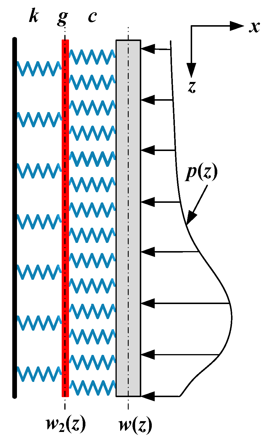
2.2. Lateral Response Analysis of a Single Pile in Kerr Foundation

The Pasternak foundation model adds a variable elastic deformation coefficient to the Kerr foundation model. In other words, the Kerr foundation model contains two spring layers and one shear layer of soil, as shown in Figure 1. k, c, and g are the three parameters corresponding to the Kerr foundation model. p(z), w(z), and w2(z) denote the additional load resulting from shield tunnel excavation, the lateral displacement of the pile foundation, and the shear layer of soil, respectively.
According to the pile–soil interaction model of the Kerr foundation, the following assumptions are considered:
  • The pile foundation is modeled as a cylindrical beam that rests on the Kerr foundation;
  • The shear layer in the Kerr foundation model only experiences shear deformation;
  • The pile foundation maintains constant contact with the foundation soil, with the two exhibiting well-coordinated deformation at the interface;
  • Lateral friction between the foundation and pile foundation is not accounted for.
The additional load p(z) generated by the excavation of a shield tunnel on a pile foundation should also be satisfied as the following equation:
1 + k c p z g c d 2 p z d z 2 = k U z g d 2 U z d z 2
in which c and k independently represent the stiffness of the first-layer and the second-layer soil spring [25], whose relationship is assumed as c = nk; g is the shear layer’s stiffness; and k and g can be calculated as [26]:
k = 0.65 E s D 1 v 2 E s D 4 E I 1 / 12
g = E s t 6 1 + v
where t, Es, and ν characterize the thickness of the shear layer, the elastic modulus, and the Poisson ratio of soil, respectively. D, E, and I denote the diameter of the pile foundation, the elastic modulus, and the inertia moment of the pipeline. The term EI represents flexural stiffness.
According to Equation (2), the additional load p(z) can be obtained by eliminating the higher-order approximation term as
p z = η n k n + 1 U z n 2 g n + 1 2 d 2 U z d z 2
in which η is the correction coefficient of load, and its value range is 0.4~1.0. Assuming that the pile on the Kerr foundation has a lateral displacement w(z) under the action of this load, it can be written as
w z = w 1 z + w 2 z
where w1(z) and w2(z) are the deformation of the spring and shear layer of the soil on the right side. Supposing that the stress of the pile and shear layer on the left side, respectively, are expressed as
q 1 z = c w 1 z = c w z w 2 z
q 2 z = k w 1 z
Concerning the shear layer, there exists
q 1 z = g d 2 w 2 z d z 2 + k w 2 z
In combination with Equations (7) and (9), we acquire
w z = 1 + k c w 2 z g c d 2 w 2 z d z 2
The governing equation of a pile foundation’s displacement caused by shield tunnel excavation can be written as follows:
E I d 4 w z d z 4 + q 1 z D = p z D
Substituting Equations (9) and (10) into Equation (11), the following equation can be gained:
E I g D c d 6 w 2 z d z 6 E I c + k D c d 4 w 2 z d z 4 + g d 2 w 2 z d z 2 k w 2 z = p z
and Equation (12) can be given as the finite difference form:
α w 2 i + 3 + β w 2 i + 2 + χ w 2 i + 1 + δ w 2 i + χ w 2 i 1 + β w 2 i 2 + α w 2 i 3 = p i
where α β χ δ = 1 0 0 0 6 1 0 0 15 4 1 0 20 6 2 1 E I g D c l 6 E I c + k D c l 4 g l 2 k , l= L/n refers to the length of the pile foundation divided into n segments with length L, and i = 0, 1, 2, …, (n − 1), n. For brevity of calculation, three virtual nodes are added at the top and end of the pile, corresponding to nodes −3, −2, −1, n + 1, n + 2, and n + 3 in turn.
Invoking the boundary conditions and eliminating the nodes above, the equation of a single pile’s displacement can be solved as follows:
W 2 = K 1 P
in which
W 2 = w 2 0 , w 2 1 , , w 2 n 1 , w 2 n T P = p 0 , - p 1 , , - p n 1 , - p n T
When there is no constraint at the top and tip of the pile foundation, the bending moment Ms of the soil’s shear layer, the shear force Qp, and the bending moment Mp for the exact position of the pile foundation are zero, that is
M p 0 = M p n = E I d 2 w z d z 2 i = 0 , i = n = 0 M s 0 = M s n = E I d 2 w 2 z d z 2 i = 0 , i = n = 0 Q p 0 = Q p n = E I d 3 w 2 z d z 3 i = 0 , i = n = 0
in which
d 2 w 2 z d z 2 = w 2 i + 1 2 w 2 i + w 2 i 1 l 2 d 3 w 2 z d z 3 = w 2 i + 2 2 w 2 i + 1 + 2 w 2 i 1 w 2 i 2 2 l 3
Therefore, the lateral stiffness matrix of the pile K can be obtained as
K = A 1 A 3 A 6 2 α A 2 A 5 A 7 β α A 4 A 7 δ χ β α α β χ δ χ β α . . . . . . . . . . . . . . . . . . . . . α β χ δ χ β α α β χ δ A 7 A 4 α β A 7 A 5 A 2 2 α A 6 A 3 A 1
where A 1 = δ + 2 χ + 4 β + 8 α , A 2 = χ + 2 β + 2 α , A 3 = 4 β 10 α , A 4 = β + 2 α , A 5 = δ β , A 6 = 2 β + 2 α , A 7 = χ α . After W2 is obtained, the pile foundation’s lateral displacement can be worked out by associating with Equation (7).

2.3. Lateral Response Analysis of Group Piles in Kerr Foundation

Due to the shielding effect of pile foundations on the displacement of soil, not only the influence of shield tunnel excavation on adjacent group piles should be considered but also the mutual interaction between adjacent pile foundations. Figure 2 depicts a simplified model diagram for calculating the influence of shield tunnel excavation on adjacent group piles. x1 and x2 are the horizontal distance between two piles and the tunnel axis, as shown in Figure 2, respectively, and s denotes the axial distance between pile I (front) and pile II (back).
The lateral soil displacement caused by shield tunnel excavation at the position of pile I is U1(z), which simultaneously results in the horizontal deflection of pile I, W1(z). Therefore, the shielding displacement due to the shielding effect of pile I can be described as W 1 z = U 1 z W 1 z . According to the transfer coefficient of soil displacement between piles proposed in the literature [27], the soil displacement caused by the shielding effect of pile I at the position of pile II can be obtained:
U 21 ( z ) = ψ s Δ W 1 ( z ) = U 1 z W 1 z
where ψ s = ln r m ln s ln r m ln r 0 ,   r 0 s r m 0 ,   s > r m . rm is the effective influence radius of the pile, which can be expressed as r m = χ 1 χ 2 L ( 1 v ) . Both χ 1 and χ 2 are the empirical coefficients. In Kerr’s foundation, the additional load of pile II aroused from the shielding effect of pile I on the soil is
p 21 z = η n k n + 1 U 21 z n 2 g n + 1 2 d 2 U 21 z d z 2
Subsequently, the horizontal displacement W21(z) of pile II caused by the shielding effect of pile I on soil can be recovered by substituting Equation (18) into Equations (10) and (14). The horizontal displacement of pile i due to shielding tunnel excavation is expressed as Wi(z). Wij(z) represents the horizontal displacement of pile i due to the shielding effect of pile j on soil. The horizontal displacement Wii(z) of pile i under the joint influence of shield tunnel excavation and adjacent piles is characterized as
W i i z = W i z + j = 1 m W j i z ( j i )

3. Lateral Displacement of Pile Foundation Considering the Effect of Lateral Soil

3.1. Lateral Response Analysis of a Single Pile in the Kerr Foundation

As shown in Figure 3a, the additional loads generated by the shield tunnel excavation not only act on the pile foundation but also significantly affect the soil next to the piles, parallel to the tunnel axis. The soil surrounding the piles also affects the displacement of the pile foundation, due to the inconsistent deformation of the ground and the pile foundation, as shown in Figure 3b.
When the Kerr foundation model is adopted to analyze the influence of soil on a pile foundation, fundamental assumptions are made about the following:
  • The parameters of lateral soil parallel to the tunnel axis beside the pile foundation are consistent with the foundation soil;
  • The lateral forces on the pile are T1 and T2, which are transferred to both sides of the pile through the shear layer of soil;
  • The pile foundation is always in close contact with the soil next to the pile, and the deformation of the pile foundation is consistent with that of the soil’s shear layer around the pile on the Kerr foundation;
  • The additional load caused by shield tunnel excavation acts on the pile foundation and lateral soil in the meantime, supposing that the load’s influence range is wide enough.
For any plane z = z0, the governing equation of deformation for the soil’s shear layer beside the pile under the action of additional load p is
p y = k U ¯ y g d 2 U ¯ y d y 2
where U ¯ y is the deformation of the soil’s shear layer around the pile along the y-axis direction. When y D / 2 , the general solution of Equation (20) can be obtained as follows:
U ¯ y = C 1 e k / g ( y D / 2 )
As shown in Figure 4, wu(z) is the particular solution of Equation (21) when y = y0. The plane of y = y0 is outside the effective influence range of the pile foundation. Hence, we can calculate Equation (20) as
U ¯ z   , y = C 1 e k / g ( y D / 2 ) + w u z
Assuming that the pile foundation is always in contact with the soil adjacent to the pile, the deformation of the shear layer of the soil around the pile, located at y = D/2, is similar to the shear layer deformation (denoted as w2) of soil in the Kerr foundation. Therefore, it can be solved by following the equation below:
C 1 = U ¯ w u = w 2 w u
U ¯ z , y = w 2 z w u z e k / g ( y D / 2 ) + w u z
Then, the force on the pile foundation can be expressed as
T 1 z = T 2 z = g d U ¯ z , y d y = w u z w 2 z k g
in which wu(z) is the deformation of the soil’s shear layer caused by the additional load on the y = y0 plane due to shield tunnel excavation, and then the governing equation of wu(z) can be obtained as
p z = η n k n + 1 w u z n 2 g n + 1 2 d 2 w u z d z 2
The governing equation of a pile foundation’s deformation considering the influence of soil besides the pile on the pile foundation can be written as follows:
E I d 4 w z d z 4 + q 1 z D = 2 T 1 z
Substituting Equations (9), (10), and (25) into Equation (27) can generate the following equations:
E I 2 c g k d 6 w 2 z d z 6 E I c + k 2 c g k d 4 w 2 z d z 4 + D 2 g k d 2 w 2 z d z 2 D 2 k g + 1 w 2 z = w u z
In addition, Equation (28) can also be expressed using the finite difference form, as follows:
γ 1 w 2 i + 3 + γ 2 w 2 i + 2 + γ 3 w 2 i + 1 + γ 4 w 2 i + γ 3 w 2 i 1 + γ 2 w 2 i 2 + γ 1 w 2 i 3 = w u i
and
γ 1 γ 2 γ 3 γ 4 = 1 0 0 0 6 1 0 0 15 4 1 0 20 6 2 1 E I 2 c l 6 g k E I c + k 2 c g k l 4 D 2 l 2 g k D 2 k g + 1
Based on the unconstrained boundary conditions at the top and tip of the pile foundation and eliminating the nodes of −3, −2, −1 and n + 1, n + 2, n + 3, the governing equation of a single pile can be given as
W 2 = K u 1 w u
where w u = w u 0 , w u 1 , , w u n 1 , w u n T , Ku denotes the lateral stiffness matrix of the pile in the x-direction of soil, which can be expressed as
K u = B 1 B 3 B 6 2 γ 1 B 2 B 5 B 7 γ 2 γ 1 B 4 B 7 γ 4 γ 3 γ 2 γ 1 γ 1 γ 2 γ 3 γ 4 γ 3 γ 2 γ 1 . . . . . . . . . . . . . . . . . . . . . γ 1 γ 2 γ 3 γ 4 γ 3 γ 2 γ 1 γ 1 γ 2 γ 3 γ 4 B 7 B 4 γ 1 γ 2 B 7 B 5 B 2 2 γ 1 B 6 B 3 B 1
in which B1 = γ4 + 2γ3 + 4γ2 + 8γ1, B2 = γ3 + 2γ2 + 2γ1, B3 = −4γ4 − 10γ1, B4 = γ2 + 2γ1, B5 = γ4γ2, A6 = 2γ2 + 2γ1, A7 = γ3γ1. Meanwhile, the lateral deformation W2 of the soil’s shear layer, considering the effect of soil beside the pile in the Kerr foundation model, can be solved. The lateral displacement W of the pile foundation caused by shield tunnel excavation can be obtained by combining with Equation (7).

3.2. Lateral Response Analysis of Group Piles in Kerr Foundation

As a result, the same procedure solution as in Section 2.2 can be adapted to work out the lateral displacement of group piles in the Kerr foundation caused by shield tunnel excavation, considering the effect of lateral soil, as follows:
W i i z = W i z + j = 1 m W j i z ( j i )

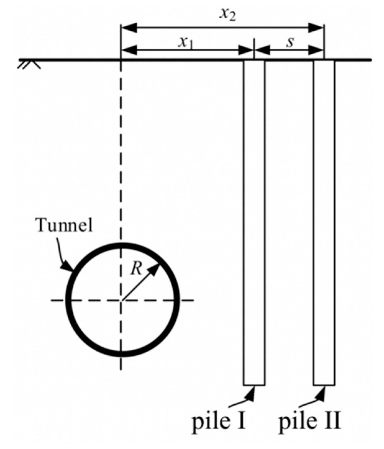
4. Verifications of the Analytical Solution

The 3D boundary element program GEPAN, which considers the three-dimensional effect of lateral soil in the solution process, was utilized to verify the accuracy of the method proposed in this paper. Loganathan [18] simulated the impact of shield tunnel excavation on the horizontal displacement of adjacent 2 × 2 group piles using the 3D boundary element program GEPAN. The soil was assumed to be a homogeneous and isotropic elastic medium with a constant soil strength of Cu = 60 kPa in the model above. The soil modulus was Es = 24 MPa. Piles were cylindrical structures made of uniform, isotropic elastic material with fixed elastic parameters. In the computer program GEPAN, a typical pile element discretization established the pile model. Both the piles and the surrounding soil mass deformed elastically, and the principle of superposition was applicable. Moreover, there was no slip between the piles and the soil at the interface. The distance between the front pile, the back pile, and the tunnel axis were 4.5 m and 6.9 m, respectively, as shown in Figure 5. The axial distance between the two piles was s = 2.4 m. The remaining calculation parameters related to the method in this paper are shown in Table 1.
Figure 6 shows the lateral displacement of the soil at the center positions of the front and back piles using the two-stage method. It is clear from the figure that the maximum lateral displacement of the soil was reduced significantly as the horizontal distance increased. Figure 7 and Figure 8 show comparisons of lateral displacement and bending moment of the front pile and the back pile obtained using the simplified calculation method in this work with those from GEPAN [18] and the method in [22]. It can be seen that the maximum lateral displacement and bending moment for the pile obtained using the three calculation methods were located near the tunnel axis, both the front pile and the back pile. The calculation results with and without considering the lateral soil were very similar to those from GEPAN when using the method presented in this paper to calculate the lateral displacement of adjacent group piles caused by shield tunnel excavation. What is more, the results in this work were more accurate than those from Zhang [22], especially in calculating the lateral displacement of the back pile. Moreover, the error in calculating the bending moment of the front pile was significantly smaller than in the work of Zhang [22]. Consequently, what has been discussed above proves the accuracy of the method proposed in this work.

5. Discussions

To analyze the impact of various factors on the deflection and bending moment of group piles using the method proposed in this paper, the following example was taken for analysis. The diameter R and the depth of the tunnel axis were 3 m and 20 m, respectively. A ground loss ratio ε0 of 2.5% was considered. The soil’s elastic modulus and Poisson ratio were 20 MPa and 0.3, respectively. The diameter D and the depth of the single pile were 0.6 m and 25 m, respectively. The elastic modulus of the single pile was selected as 30 GPa. Assuming that there were two piles with unconstrained top and tip, the front pile and back pile were located 5 m and 8 m from the tunnel axis, respectively. Moreover, the other parameters remained unchanged when analyzing a certain parameter’s influence on the pile foundation’s vertical displacement in the following.

5.1. Influence of the Stiffness of Soil Spring

Figure 9 shows the lateral displacement and bending moment of the front pile with different stiffnesses of soil spring c. This parameter represents the stiffness of the soil spring between the shear layer and the pile in the Kerr foundation model. It can be seen that the stiffness of soil spring c had a significant influence on the lateral displacement of the adjacent pile. Both the lateral displacement and bending moment of the front pile decreased with the increase in soil spring stiffness c, and the magnitude of the impact also gradually decreased. Increasing the soil spring stiffness resulted in a more significant reaction force for the Kerr foundation to the pile, reducing the front pile’s displacement and bending moment.

5.2. Influence of Pile–Tunnel Distance

Figure 10 shows the front pile’s lateral displacement and bending moment as the distance between the front pile and the tunnel axis were increased from 5 m to 8 m, while the pile spacing remained unchanged. The front pile’s maximum lateral displacement and bending moment occurred at the centerline of the tunnel. As the distance between the front pile and tunnel increased, the front pile’s maximum lateral displacement and bending moment decreased. This happened because the lateral displacement of the soil decreased, and the impact on the adjacent pile lessened.

5.3. Influence of the Ground Loss Ratio

Figure 11 illustrates the front pile’s lateral displacement and bending moment under varying ground loss ratios ε0. The graph in Figure 11 shows that, as the ground loss ratio increased from 0.5% to 2%, the front pile’s lateral displacement and bending moment gradually increased. It is understandable that a higher ground loss ratio (ε0) results in more significant lateral displacement of the soil, due to the excavation of the shield tunnel. This displacement put more load on the adjacent pile, resulting in greater lateral displacement and bending moment of the front pile.

5.4. Influence of Pile Diameter

The graph in Figure 12 illustrates how the front pile’s lateral displacement and bending moment changed with different pile diameters. It is clear from the graph that changes in pile diameter had a significant impact on both lateral displacement and bending moments of the front pile. As the pile diameter D increased from 0.4 m to 1.0 m, the lateral displacement decreased slowly, while the bending moment increased. This is because the flexural rigidity EI increased with the diameter, leading to less deformation under the same load strength due to soil displacement but also to an increase in bending moment.

6. Conclusions

This paper proposed a simplified method for simulating the pile–soil interaction caused by shield tunnel excavation. The process is based on the Kerr foundation model with three parameters and considers the influence of lateral soil displacements beside the pile. Theoretical solutions are presented to evaluate the effects of tunneling on the lateral displacements and bending moments of a single pile and group piles.
The presented method was validated by comparing it with existing solutions obtained from the boundary element program GEPAN. In addition, the proposed method was used to calculate the displacements and bending moments of a single pile and group piles induced by tunneling, while considering the effects of lateral soil displacements. A parametric analysis was conducted to assess the influence of various factors, including the stiffness of soil spring c, pile–tunnel distance, ground loss ratio ε0, and pile diameter D on group piles’ deflection and bending moment.
After an in-depth discussion of the results, the following conclusions can be drawn:
  • For a more accurate calculation of the bending moment of a pile during shield tunnel excavation, it is essential to consider the influence of lateral soil displacements around the pile. Ignoring this influence can result in less accurate calculations. Therefore, accounting for the impact of lateral soil around the pile is crucial for achieving higher accuracy;
  • The lateral displacement of the pile caused by tunnel excavation increases and then decreases with depth, with the maximum displacement and bending moment occurring at the depth of the tunnel axis;
  • Increasing soil spring stiffness or pile diameter reduces lateral displacement but increases the bending moment;
  • The pile’s lateral displacement and bending moment decrease with increasing pile–tunnel distance, while they increase with an increase in the ground loss ratio.

Author Contributions

Conceptualization, N.W.; Software, H.J.; Formal analysis, H.J.; Writing—original draft, H.J.; Writing—review & editing, N.W., H.D. and L.G.; Funding acquisition, N.W. and H.D. All authors have read and agreed to the published version of the manuscript.

Funding

This research was funded by the National Natural Science Foundation of China, grant number 52168047 and 52208344.

Data Availability Statement

Not applicable.

Conflicts of Interest

The authors declare no conflict of interest.

References

  1. Basile, F. Effects of tunnelling on pile foundations. Soils Found. 2014, 54, 280–295. [Google Scholar] [CrossRef]
  2. Boonyarak, T.; Phisitkul, K.; Ng, C.W.; Teparaksa, W.; Aye, Z.Z. Observed ground and pile group responses due to tunneling in Bangkok stiff clay. Can. Geotech. J. 2014, 51, 479–495. [Google Scholar] [CrossRef]
  3. Loganathan, N.; Poulos, H.; Stewart, D. Centrifuge model testing of tunnelling-induced ground and pile deformations. Geotechnique 2000, 50, 283–294. [Google Scholar] [CrossRef]
  4. Marshall, A.M.; Mair, R.J. Tunneling beneath driven or jacked end-bearing piles in sand. Can. Geotech. J. 2011, 48, 1757–1771. [Google Scholar] [CrossRef]
  5. Ng, C.W.W.; Lu, H.; Peng, S. Three-dimensional centrifuge modelling of the effects of twin tunnelling on an existing pile. Tunn. Undergr. Space Technol. 2013, 35, 189–199. [Google Scholar] [CrossRef]
  6. Ng, C.W.W.; Soomro, M.A.; Hong, Y. Three-dimensional centrifuge modelling of pile group responses to side-by-side twin tunnelling. Tunn. Undergr. Space Technol. 2014, 43, 350–361. [Google Scholar] [CrossRef]
  7. Lu, H.; Shi, J.; Ng, C.W.; Lv, Y. Three-dimensional centrifuge modeling of the influence of side-by-side twin tunneling on a piled raft. Tunn. Undergr. Space Technol. 2020, 103, 103486. [Google Scholar] [CrossRef]
  8. Chiang, K.-H.; Lee, C.-J. Responses of single piles to tunneling-induced soil movements in sandy ground. Can. Geotech. J. 2007, 44, 1224–1241. [Google Scholar] [CrossRef]
  9. Franza, A.; Marshall, A.M. Centrifuge and real-time hybrid testing of tunneling beneath piles and piled buildings. J. Geotech. Geoenvironmental Eng. 2019, 145, 04018110. [Google Scholar] [CrossRef]
  10. Lee, G.T.; Ng, C.W. Effects of advancing open face tunneling on an existing loaded pile. J. Geotech. Geoenvironmental Eng. 2005, 131, 193–201. [Google Scholar] [CrossRef]
  11. Liyanapathirana, D.; Nishanthan, R. Influence of deep excavation induced ground movements on adjacent piles. Tunn. Undergr. Space Technol. 2016, 52, 168–181. [Google Scholar] [CrossRef]
  12. Soomro, M.A.; Hong, Y.; Ng, C.W.W.; Lu, H.; Peng, S. Load transfer mechanism in pile group due to single tunnel advancement in stiff clay. Tunn. Undergr. Space Technol. 2015, 45, 63–72. [Google Scholar] [CrossRef]
  13. Jongpradist, P.; Kaewsri, T.; Sawatparnich, A.; Suwansawat, S.; Youwai, S.; Kongkitkul, W.; Sunitsakul, J. Development of tunneling influence zones for adjacent pile foundations by numerical analyses. Tunn. Undergr. Space Technol. 2013, 34, 96–109. [Google Scholar] [CrossRef]
  14. Hong, Y.; Soomro, M.A.; Ng, C.W.W. Settlement and load transfer mechanism of pile group due to side-by-side twin tunnelling. Comput. Geotech. 2015, 64, 105–119. [Google Scholar] [CrossRef]
  15. Fu, J.; Yang, J.; Zhu, S.; Shi, Y. Performance of jet-grouted partition walls in mitigating the effects of shield-tunnel construction on adjacent piled structures. J. Perform. Constr. Facil. 2017, 31, 04016096. [Google Scholar] [CrossRef]
  16. Chen, L.T.; Poulos, H.; Loganathan, N. Pile responses caused by tunneling. J. Geotech. Geoenvironmental Eng. 1999, 125, 207–215. [Google Scholar] [CrossRef]
  17. Loganathan, N. Analytical Prediction for Tunneling-Induced Ground Movements in Clays. J. Geotech. Geoenvironmental Eng. 1998, 124, 846–856. [Google Scholar] [CrossRef]
  18. Loganathan, N.; Poulos, H.; Xu, K. Ground and pile-group responses due to tunnelling. Soils Found. 2001, 41, 57–67. [Google Scholar] [CrossRef]
  19. Huang, M.; Zhang, C.; Li, Z. A simplified analysis method for the influence of tunneling on grouped piles. Tunn. Undergr. Space Technol. 2009, 24, 410–422. [Google Scholar] [CrossRef]
  20. Mu, L.; Huang, M.; Finno, R.J. Tunnelling effects on lateral behavior of pile rafts in layered soil. Tunn. Undergr. Space Technol. 2012, 28, 192–201. [Google Scholar] [CrossRef]
  21. Pasternak, P. On a new method of an elastic foundation by means of two foundation constants. Gos. Izd. Lit. Po Stroit. I Arkh. 1954, 1–56. [Google Scholar]
  22. Zhang, Z.; Huang, M.; Xu, C.; Jiang, Y.; Wang, W. Simplified solution for tunnel-soil-pile interaction in Pasternak’s foundation model. Tunn. Undergr. Space Technol. 2018, 78, 146–158. [Google Scholar] [CrossRef]
  23. Kerr, A.D. A study of a new foundation model. Acta Mech. 1965, 1, 135–147. [Google Scholar] [CrossRef]
  24. Zhang, D.-M.; Huang, Z.-K.; Li, Z.-L.; Zong, X.; Zhang, D.-M. Analytical solution for the response of an existing tunnel to a new tunnel excavation underneath. Comput. Geotech. 2019, 108, 197–211. [Google Scholar] [CrossRef]
  25. Vesić, A.B. Bending of beams resting on isotropic elastic solid. J. Eng. Mech. Div. 1961, 87, 35–53. [Google Scholar] [CrossRef]
  26. Tanahashi, H. Formulas for an Infinitely Long Bernoulli-Euler Beam on the Pasternak Model. Soils Found. 2004, 44, 109–118. [Google Scholar] [CrossRef]
  27. Randolph, M.; Wroth, C. Analysis of Deformation of Vertically Loaded Piles. J. Geotech. Geoenvironmental Eng. 1978, 104, 1465–1488. [Google Scholar] [CrossRef]
Figure 1. Pile–soil interaction model in Kerr’s foundation.
Buildings 13 02548 g001
Figure 2. Computational model for group piles adjacent to tunneling.
Buildings 13 02548 g002
Figure 3. Influence of tunneling on the adjacent pile: (a) additional loads applied on the pile and soil, (b) forces acting on the pile through the lateral shear layer of soil.
Buildings 13 02548 g003
Figure 4. Deformation of the shear soil layer beside the pile.
Buildings 13 02548 g004
Figure 5. Calculation model of the influence of tunneling on group piles.
Buildings 13 02548 g005
Figure 6. Lateral displacement of soil at the center position of the pile.
Buildings 13 02548 g006
Figure 7. Comparison of results between the present method and others: (a) lateral displacement and (b) bending moment of the front pile [18,22].
Buildings 13 02548 g007
Figure 8. Comparison of results between the present method and others: (a) lateral displacement and (b) bending moment of the back pile [18,22].
Buildings 13 02548 g008
Figure 9. Variations of (a) lateral displacement and (b) bending moment of the front pile with different stiffnesses of soil spring.
Buildings 13 02548 g009
Figure 10. Variations of (a) lateral displacement and (b) bending moment of the front pile with different distances between the pile and tunnel.
Buildings 13 02548 g010
Figure 11. Variations in the (a) lateral displacement and (b) bending moment of the front pile with different ground losses.
Buildings 13 02548 g011
Figure 12. Variations in (a) lateral displacement and (b) bending moment of the front pile with different pile diameters.
Buildings 13 02548 g012
Table 1. Calculation parameters.
R (m)H (m)ɛ0 (%)Es (MPa)υEp (MPa)D (m)L (m)
3201240.53 × 1040.825
Disclaimer/Publisher’s Note: The statements, opinions and data contained in all publications are solely those of the individual author(s) and contributor(s) and not of MDPI and/or the editor(s). MDPI and/or the editor(s) disclaim responsibility for any injury to people or property resulting from any ideas, methods, instructions or products referred to in the content.

