Article

Effects of 3D Concrete Printing Phases on the Mechanical Performance of Printable Strain-Hardening Cementitious Composites

1
Faculty of Civil Engineering and Geosciences, Delft University of Technology, 2628 CE Delft, The Netherlands
2
School of Engineering and Design, Technical University of Munich, 80333 Munich, Germany
3
Department of the Built Environment, Eindhoven University of Technology, 5612 AZ Eindhoven, The Netherlands
*
Author to whom correspondence should be addressed.
Buildings 2023, 13(10), 2483; https://doi.org/10.3390/buildings13102483
Submission received: 31 August 2023 / Revised: 22 September 2023 / Accepted: 28 September 2023 / Published: 29 September 2023
(This article belongs to the Special Issue 3D Concrete Printing: Materials, Process, Design and Application)

Abstract

:
Several studies have shown the potential of strain-hardening cementitious composites (SHCC) as a self-reinforcing printable mortar. However, papers published on the development of three-dimensional printable SHCC (3DP-SHCC) often report a discrepancy between the mechanical properties of the cast and printed specimens. This paper evaluates the effect of each successive phase of the printing process on the mechanical properties of the composite. To this end, materials were collected at three different stages in the printing process, i.e., after each of mixing, pumping, and extruding. The collected 3DP-SHCC materials were then cast in specimen moulds and their mechanical properties after curing were obtained. The resulting findings were juxtaposed with the mechanical properties of the specimens derived from a fully printed 3DP-SHCC element, and our findings indicate that while the density and the compressive strength are not significantly influenced by the printing process, the flexural and tensile strength, along with their associated deflection and strain, are strongly affected. Additionally, this research identifies the pumping phase as the primary phase influencing the mechanical properties during the printing process.

1. Introduction

As a new manufacturing technology within the field of construction, three-dimensional concrete printing (3DCP) has undergone rapid development over the past decade. This technical innovation has the potential to allow for the manufacturing of complicated geometries in an automated setup. Additionally, it provides benefits such as material savings, reduction of manual labor, and increased efficiency in the production of complex concrete elements. In recent years the technology has delivered multiple case studies [1], from houses to bridges, that showcase its potential.
However, 3DCP has one challenge that is inherent to its nature, namely, concrete’s poor tensile strength and ductility. Due to this material characteristic, printed concrete elements are prone to failing without warning when subjected to high tensile forces, and the structural safety of the printed elements is a subject of concern. As a solution, 3D printed elements have been designed to be loaded in compression only [2], occasionally aided by the addition of post-tensioned reinforcement. However, this compromises the potential benefits of 3DCP, namely, design based on the principle of ‘form following force’ [3,4] and reduced material usage.
One of the research trajectories to overcome this challenge in 3DCP is the development of Strain-Hardening Cementitious Composites for 3D Printing (3DP-SHCC). Strain-Hardening Cementitious Composites (SHCC) are characterized by their high tensile ductility and strain hardening behavior, which they derive from a small volume (1–2 vol%) of incorporated microfibres. These mechanical characteristics make the material attractive for additive manufacturing, offering increased structural safety due to its ability to undergo tensile strain without losing the capacity to withstand tensile stress. Therefore, the application of SHCCs as a printing material can greatly improve design flexibility and material efficiency.
Additionally, SHCC offers several advantages for (post)-reinforced printed elements. For instance, it can withstand tensile splitting forces encountered in the commonly used post-tensioned prestress reinforcement within 3DCP. Furthermore, in a novel 3DCP reinforcement technology where helical reinforcement is automatically integrated into 3D printed concrete structures, SHCC can enhance the material confinement and rebar bonding, thereby improving the overall performance of the steel-reinforced concrete printed elements [5,6].
The mechanical principle of SHCC is based on the formation of multiple stable cracks under tensile loading. When the concrete matrix develops its initial microcrack, the fibers are able to take over the tensile forces of the composite matrix. As the fibers successfully bridge this crack, the equilibrium of forces within the concrete element is restored and the crack is stabilized. As the applied tensile force continues to increase, the concrete eventually cracks in a different location and the same process takes place. This cycle repeats until the imposed tensile stress is higher than the fibre-bridging capacity of the formed cracks. At this point, the crack localizes, leading to the ultimate failure of the material. In order for a material to exhibit this behavior, it must satisfy two specific micro-mechanical criteria, namely, the strength and energy criteria [7].
The strength criterion specifies that the cracking strength of the matrix should be lower than the maximum fibre bridging capacity of the existing cracks. The energy criterion, in short, ensures that the fibers are able to bridge a matrix crack and keep it stable. Here, the interface bond between the fiber and its surrounding matrix plays a crucial role. If this interface is too strong, the fibers will break, whereas if it is too weak the fibers will be pulled out from the matrix. In both scenarios, the complementary energy is insufficient to maintain a stable crack state. In order to exhibit strain-hardening behavior, it is essential for the fibers to possess just the right degree of freedom for deformation, enabling them to accumulate the necessary complementary energy to attain a stable crack state. This enables the formation of multiple stable cracks, and consequently results in strain-hardening behavior [7].
Initial designs [8,9,10,11] have demonstrated the high potential of SHCC as a group of self-reinforcing printable materials [12]. Currently, a growing community of researchers is focused on the development of 3DP-SHCC for large-scale industrial 3D printing systems.
When it comes to any material, researchers rely on the mechanical properties retrieved from experiments. Unfortunately, full-scale concrete printing sessions are too time- and material-intensive for quick feedback on material adjustments. Thus, in order to keep the iteration time during material development short, researchers often conduct their experiments on cast specimens. In recent years, however, multiple research papers have presented discrepancies between cast and printed specimens [13,14,15,16,17,18]. Le et al. [14] presented thorough research into material and mechanical properties for both cast and printed specimens. They found that the density of the printed specimens was 4.5% higher and the flexural strength increased from 11 MPa (cast) to 13–15 MPa (printed). However, lower values were reported for compressive strength, at 5–30% for the printed specimens. This reduction in compressive strength for printed elements is often found in the literature, where contradicting reports can be found for the density. A recent study of Seo et al. [17], analysed the density and compressive strength of different mixtures and curing methods. They concluded that the density of the cast specimens showed a small increase for multiple specimen types.
These differences seem to be even more pronounced when using SHCC for 3D concrete printing, as multiple researchers have reported high deviations in flexural and tensile deformation capacity between cast and printed specimens [9,11,19,20,21], with reductions of 25% to 38% in tensile strain capacity.
To achieve strain-hardening capacity, the material must not only contain a sufficient fibre volume, its cementitious matrix has to be tailored accordingly in order to comply with two material-specific requirements, namely, the strength criterion and the energy criterion [22,23]. Changes in material properties (hydration products, material density [24], rheology [25], and fibre dispersion [26], among others), may lead to alterations and consequent noncompliance with the two micromechanical criteria.
Numerous phenomena have the potential to influence the material and its mechanical properties throughout the printing process. Consequently, cast specimens do not necessarily provide a reliable indication of the actual behaviour of printed material. In the field of 3D concrete printing, it is generally agreed that the interlayer between the subsequently extruded filaments can affect the mechanical performance of the printed element. The quality of adhesion between two subsequent layers depends on both the fresh material properties and printing settings, such as the time gap (interlayer time) [14,15,27], print speed [15], nozzle height [28], moisture content [29], and the structuration rate of the material [30,31].
The pumping phase can influence the material and mechanical properties of a printed element as well. A recent study by Chaves Figueiredo et al. [32] found high variance in mechanical and material properties when the same mixture was printed at two different printing facilities while maintaining the same printing settings.
The influence of pumping on the material and mechanical properties of concrete has been the subject of a considerable number of studies [33,34,35]. The overview by Li et al. [33] on the effect of pumping on concrete mixtures reported the changes in rheology properties and air void content. Other literature on this subject presented by Shen et al. [35] concluded that pumping may accelerate the hydration process, causing a reduction in the dormant period and the setting period of up to 27 and 28%, respectively. Shen argued that this is the main cause of the increase in dynamic yield stress observed in pumped concrete.
In the domain of printable fibre-reinforced composites (FRC), which includes SHCC, the microfibres may play a substantial role in the observed variations in mechanical properties between cast and printed composites.
Hambach and Volkmer [36] found that fibre alignment within a printed fibre-reinforced element can be achieved when the ratio of fibre length/nozzle diameter is larger than one. Similar to this approach, Me et al. [37] printed FRC using a narrow nozzle diameter, ensuring that the fibres were positioned vertically within the nozzle before extrusion. The evaluation of the mechanical properties was carried out in the three principal orthogonal directions and compared to conventionally cast specimens created from the identical FRC mix. In the cast specimen, the assumption is made that the fibres are arranged in a random manner. Their research concluded that fibre alignment was achieved and that it strongly affected the mechanical properties in different directions. Chaves Figueiredo et al. [21] investigated the orientation of the fibres from a beam which was printed with a nozzle larger that the maximum fibre length (fibre length: 8 mm, rectangular nozzle size: 10 × 50 mm). In this scenario, it was found that the extrusion process oriented the fibres diagonally outwards with respect to the printing direction.
In addition to fibre orientation, fibre agglomeration, that is, the clustering or grouping together of individual fibers within a material, has been reported for printable SHCC [11,38,39]. Fibre agglomeration can strongly affect the robustness of SHCC performance, especially its tensile strain capacity [7,40].
In order to understand the difference between cast and printed 3DP-SHCC specimens, in this study we research the mechanical properties of 3DP-SHCC throughout the printing process. The printing of a concrete element can generally be seen as a succession of four phases: mixing of material, pumping of material, extrusion of material, and finally printing of the material. The objective of this study is to determine the influence of each of these printing phases on mechanical properties and to identify potential bottlenecks within this process.

2. Materials and Methods

2.1. Material

For this study, we used Mix D, which was developed previously by van Overmeir et al. [19]. The mix is composed of the following raw materials: CEM I 42.5 N, silica fume (SF), blast furnace slag (BFS), limestone powder (LS), river sand (Sand), superplasticiser (SP), and viscosity modifying agent (VMA). The material composition can be found in Table 1.
For the fibre reinforcement, RECS15 polyvinyl alcohol (PVA) fibres from Kuraray GmbH were used in the composites. The specifications of the RECS15 fibre can be viewed in Table 2.
The material was mixed in batches of 3.5 L in a A200-N Hobart planetary mixer. The mixing procedure is described below:
  • Two minutes mixing of all dry materials, including the fibres, SP, and one third of the VMA.
  • One minute mixing while water is added to the dry materials.
  • One minute mixing of the wet materials.
  • The remaining two thirds of the VMA is added to the wet materials.
  • Two minutes mixing of the wet materials.
In order to achieve good viscosity properties during mixing and ensure sufficient fibre dispersion, the mixing procedure prescribes adding the VMA in two phases.

2.2. Research Methodology

To research the effect of each printing phase on the hardened properties, in our experimental program we collected the material after each subsequent printing phase, referred to as phases A–C. In Phase A, material is collected directly after mixing; in Phase B, the material is collected directly after the rotor/stator of the pump; and in Phase C, the material is collected after being pumped through the hose and extruded from the nozzle. The collected material was then cast in moulds without applying any additional compaction technique to the material, the filled moulds were covered with plastic foil, and wet cloths were placed underneath the foil to keep the relative humidity close to 100%. The specimens were demoulded after 24 h of curing, after which they were cured in water at a constant temperature of 20 °C. In addition to the cast specimens, beams with a length of 800 mm and a height of 6 layers were printed. Directly after printing, wet cloths were divided over the printing bed, and the whole was then covered with plastic foil. Beams were sawn to test specific specimen sizes after 7 days of curing. The specimens retrieved from these beams are referred to as Phase D. Curing took place under the same conditions as the cast specimens from Phases A–C. All specimens were removed from the curing condition one day prior to testing.
Both the printing of the composite and the material collection and casting took place within one printing session.
Phase A
Cast: Mixed
Phase B
Cast: Mixed and pumped
Phase C
Cast: Mixed, pumped and extruded
Phase D
Printed: Mixed, pumped, extruded and printed
For the printing of the composite and the material collection, the printing facilities of the Eindhoven University of Technology (TU/e) were used [41]. For pumping, an M-Tec P20 Connect cavity pump was employed featuring a D8-2 Rotor/stator and a bespoke transport screw. Figure 1 presents the pump and its specific equipment.
The principle behind a progressive cavity pump is that a helical rotor (stainless steel) turns inside a helical stator (elastomeric material). As the rotor revolves inside the stator, one cavity opens as the other closes. The cavities progress along the stator while the rotor turns, moving a constant volume of material through the pump. This principle is further visualized in Figure 2.
A hose with a 25.4 mm diameter and a length of 5 m connects the pump to an extrusion nozzle with a downward orientation and a cross-section of 40 × 12 mm 2 . The cross-sectional opening of the nozzle was set to be significantly larger than the fibre length of 8 mm in order to minimize the fibre alignment, as reported by [21,36,37]. The beams for the Phase D specimens were printed at a speed of 28.5 mm/s.

2.3. Experimental Program

To assess the hardened mechanical properties, specimens were subjected to three types of mechanical tests: compression tests, four-point bending tests, and uniaxial tensile tests.

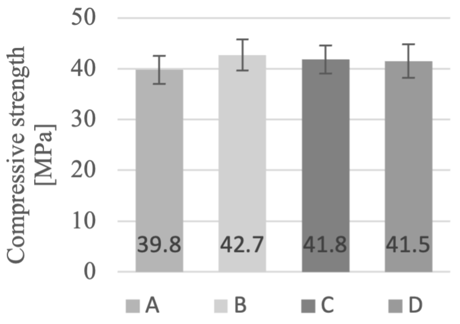
2.3.1. Compression Test

The compression tests were conducted 27 days after casting and printing of the specimens. Prior to testing, cubed specimens with edges of 35 mm (±1 mm) were weighed to determine their density. A servo-hydraulic machine was used for the compression test, and the tests were performed with a constant load rate of 2.4 kN/s in accordance with ASTM C-39. Seven specimens were tested for each of the cast Phases A–C. The Phase D specimens were extracted from the six-layer high beams. During specimen preparation, it was ensured that all cubes consisted of three layers and two interlayer zones. Six specimens were tested per orientation u, v, and w, as defined previously by the RILEM Technical Committee 304-ADC [45].

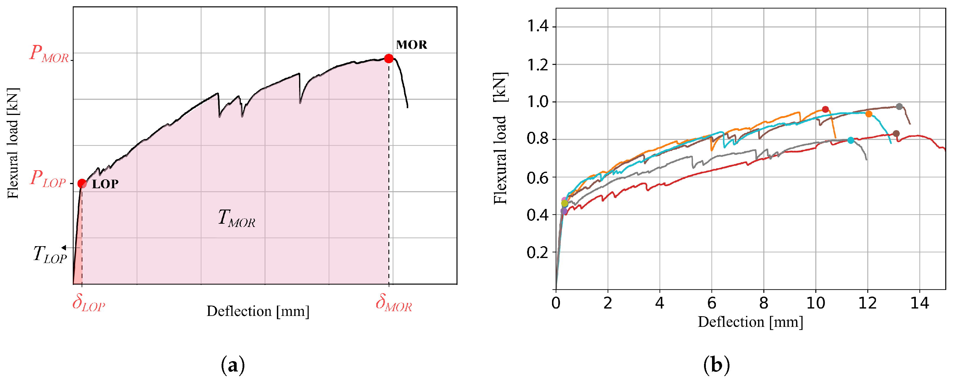
2.3.2. Four-Point Bending Test

To determine the flexural strength and deflection capacity of the cast and printed specimens, four-point bending tests were conducted. The slab-shaped specimens with a size of 30 mm (b) × 8 mm (h) × 150 mm (l) were tested after 29 days of curing. Phase D specimens were extruded from the printed beams, with careful consideration of the interlayer zone locations. The height of one single layer within the printed beam was ±14 mm, enabling the extraction of test specimens without the presence of an interlayer zone.
All specimens were tested in orientation v.u (load perpendicular to the printing plane) [45]. The four-point bending tests were conducted using an Instron 8872 servo-hydraulic testing system, with an effective load span of 120 mm and a spacing between the span rods of 40 mm. These tests were executed in displacement-controlled mode with a testing speed of 0.005 mm/s.
To measure the effective displacement during testing, two LVDTs were positioned on the steel components of the test set-up. It is important to note that the vertical displacement measurements were obtained by averaging the measurements from these two LVDTs. Considering their placement, the retrieved values relate to the displacement of the two middle rods. Figure 3 presents the full test setup.
The average flexural toughness ( T f ) was determined for specimens from all four phases using the approach outlined by Kim et al. [46]. This method is very suitable for assessing the overall deflection hardening capacity, as it combines both the performance of flexural stress and the corresponding deflection. For materials with deflection hardening, the flexural toughness signifies the deformation energy (J) stored within the test volume of the specimen (m 3 ). The flexural toughness is quantified by the area underneath the load–deflection (N*mm) curve [19,47]. The load was normalised for the standard specimen test volume of (30 × 8 × 120 m 3 (bxhxl)). This standardization was necessary in order to compensate for minor variations in size arising from the sawing process employed during the preparation of the Phase D printed specimens. The flexural toughness was assessed at two specific points along the load–deflection curve: the limit of proportionality (LOP), and the modulus of rupture (MOR), where MOR is defined as the point where deflection softening initiates subsequent to reaching the maximum load. Effectively, the flexural toughness at LOP ( T f , L O P ) is quantified by the area under the curve up to the LOP point, while T f , M O R ) represents the energy stored within the material until the moment at which rupture occurs. All relative parameters are presented in Figure 4.

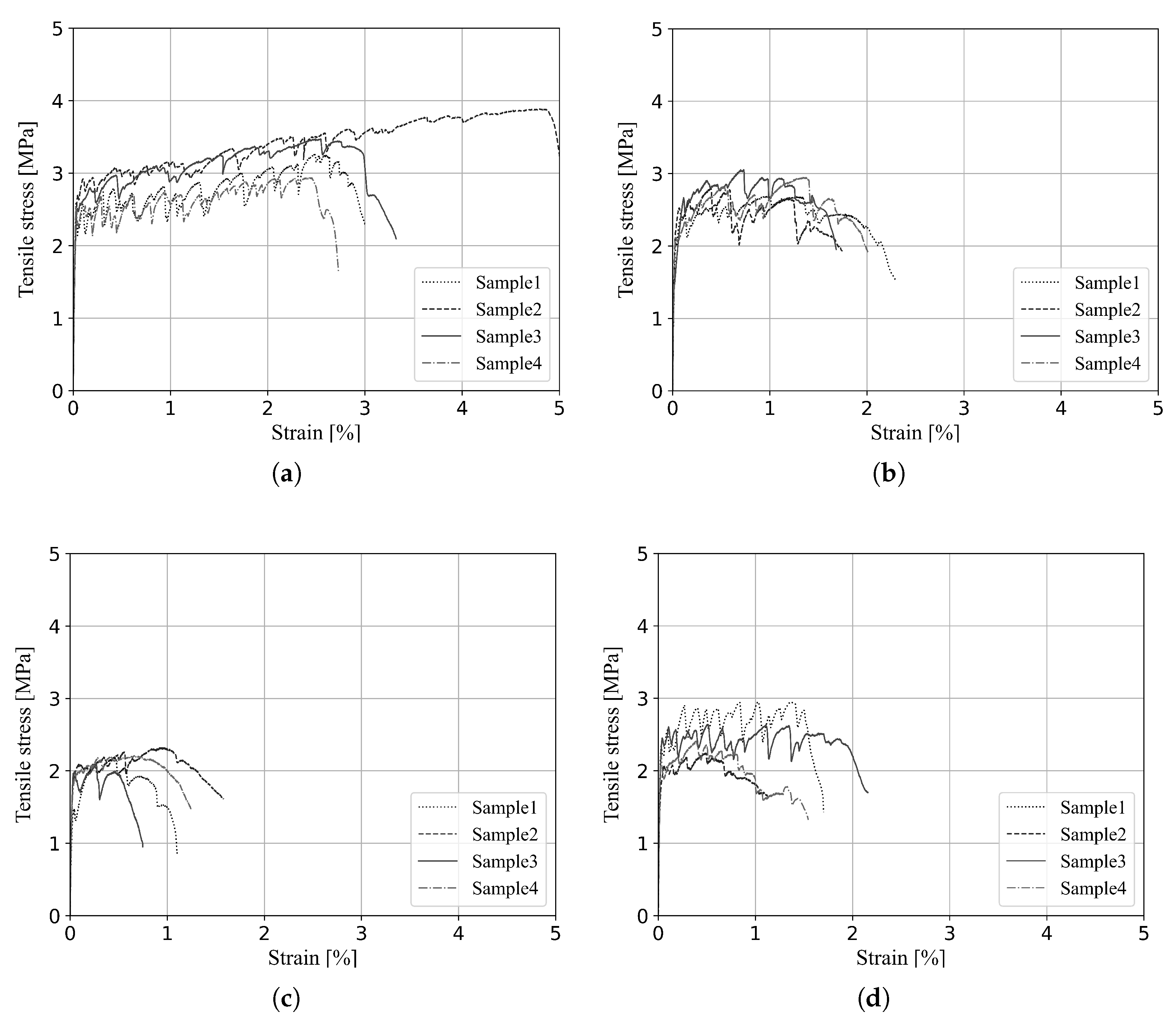
2.3.3. Uniaxial Tensile Test

To determine the tensile strength and strain-hardening capacity of the composites, uniaxial tensile tests were conducted. The cast specimens of Phases A–C were directly cast into dogbone-shaped moulds. An elaborate description of the specimen preparation approach used for the printed specimens can be found in our previous work [48]. The dogbone-shaped specimens were tested in the printing direction with orientation u. The uniaxial tensile tests were performed on an Instron 8872 servohydraulic testing device. The tests were conducted in deformation-controlled mode with a displacement rate of 0.5 μm/s, resulting in a strain rate of 5 microstrain/s. The average measurement of two LVDT sensors was used to control the vertical speed of displacement. The tensile test set-up is presented in Figure 5.
Based on the findings obtained from the uniaxial tensile tests, the tensile toughness values were quantified by the area underneath the tensile stress–strain curve. The point where the modulus of rupture is reached within tensile test specimens is often less evident, and does not always overlap with σ t , M A X , as is the case for the flexural specimens. Therefore, the definition of σ M O R must be further specified as follows: the tensile stress at the last crack before strain softening starts to occur, considering that σ t , M O R > σ t , L O P .

3. Results and Analysis

3.1. Compression Test

The compression test involved examining seven individual specimens within each phase of the study. The average values of compressive strength for each phase are graphically depicted in Figure 6. The compressive strength of 41.5 Mpa for Phase D represents the average of the three orientations, with compressive strengths of u (42.0 MPa), v (43.3 MPa), and w (39.0 MPa).
Our observations reveal a consistent compressive strength across all four phases, with a slight but noticeable increase between Phase A and Phases B–D. This implies a potential variation in compressive strength between these phases. However, it is important to consider the values of the corresponding relative standard deviations (RSTD), which remain consistent at approximately 6.5% to 8% for all phases. As the increase between Phases A and B falls within these error margins, no solid conclusion can be drawn based on these results.
This small increase in compressive strength between cast and printed composites is commonly encountered in the context of 3DP-SHCC, as documented in previous research [8,9,11,19,21,49]. However, these outcomes are in contrast with the prevailing consensus for “plain” printable mortars, for which it is often reported that printed specimens exhibit reduced compressive strength compared to their cast counterparts [14,15,18].
The average apparent density measurements are presented in Figure 7. The compressive strength presented for Phase D presents the average of the three orientations u (41.5), v (42.2), and w (39.6). Similar to the compressive strength findings, the material density shows relatively stable values throughout the four phases of the printing process. Interestingly, a distinct elevation in density is noted between Phase A and Phase B, constituting a 3% increase; this can be related to the reduction of air voids, which is a common observation in pumped concrete [33].
Considering that both the compressive strength and the density display distinct increases between Phase A and Phase B, it is reasonable to declare that the pumping phase plays a role in the increase of the material density, consequently leading to an increase in the compressive strength.

3.2. Four-Point Bending Test

Five specimens per phase were tested for their flexural strength and displacement capacity in the four-point bending test. The flexural stress–deflection curves are presented in Figure 8, in which a clear distinction is observable between Phase A and Phases B–D. While Phase A demonstrates an extended phase of deflection hardening, with a consistent and linear slope from LOP to MOR, Phases B–D exhibit more restricted deflection capacity and display increased variability among the specimens.
The average results of the four-point bending tests are presented in Table 3 along with their standard deviations. Three observations can be made from this table. In regard to the flexural stress at the LOP and its corresponding deflection, it can be observed that these values do not significantly deviate over the phases. This is in contrast with the values found for the maximum flexural strength, which displays a significant decrease of 27% between Phase A (9.02 MPa) and Phase B (6.62 MPa). Following this, the flexural strength remains relatively consistent from Phase B to Phase C, before experiencing a further 10% decline between Phases C and D. The same general trend can be seen for the deflection at maximum flexural stress, with reductions of 54%, 16%, and 43% measured between the subsequent printing phases. Additionally significant is the finding that the overall flexural deflection was reduced by an astonishing 78% between the cast and printed composites.
The development of the flexural toughness measures T f , L O P and T f , M O R throughout the four printing phases is presented in Figure 9. It can be seen that T f , L O P is fairly stable, with 1.0 ± 0.12 ( × 10 2 ) Nm, although it exhibits high variance within all four phases, while T f , M O R undergoes more pronounced changes over the four phases. Here, a significant drop of 61% is present between Phase A (1.37 Nm) and Phase B (0.54 Nm). This is significantly higher than the observed decrease for the one-dimensional values of the maximal flexural stress and its corresponding deflection. The impact of the pumping phase becomes abundantly clear when reviewing the values of T f , M O R .
Another reduction in flexural toughness was observed between the cast specimens from Phase C (0.43 Nm) and the printed specimens from Phase D (0.24 Nm). When reviewing these results, it is worth considering that both the printed and the cast specimens that were tested in the four-point bending test lacked an interlayer. Consequently, any reduction in mechanical performance between Phase C and Phase D cannot be attributed to this. Nevertheless, the cast specimens from Phases A–C were cast in a mould with a predetermined height of 8 mm while ensuring that all fibres were fully embedded within this height. This was not the case for Phase D specimens, which were extruded from the printed beams; hence, fibres may have been only partially embedded due to the sawn edges. This difference in specimen preparation may possibly have affected the mechanical results, and could be the cause of the strong reduction in flexural hardening capacity between Phases C and D.
Over the course of the full printing process, T f , M O R was reduced by 82%.

3.3. Uniaxial Tensile Test

The uniaxial tensile test was conducted on four specimens per phase. The tensile stress–strain curves of each phase are depicted in Figure 10. The average results along with their standard deviations are summarised in Table 4. The total reduction in mechanical performance over the full printing process was found to be 24% and 71% for the tensile strength and tensile strain, respectively. In correspondence with the four-point bending test results, the most significant decrease in tensile strength and strain was found between Phases A and B, where the average tensile strength dropped 15% and the tensile strain capacity decreased by 70%.
The values measured for the LOP data points are constant over the four successive phases, with the exception of Phase C, which clearly shows reduced tensile stress at the LOP.
The tensile toughness values T t , L O P and T t , M O R are presented in Figure 11, with T f , L O P showing a small and steady reduction throughout the printing process of 10% overall. These values are combined with relatively high variance between the test specimens. The tensile toughness at MOR presents a different trend, with a significant reduction throughout the printing process. As in the four-point bending test, a substantial drop can be observed between Phase A (9.61 N/mm 2 ) and Phase B (3.68 N/mm 2 ), amounting to a reduction of 62%.
In addition to the tensile stress and strain values, the T t , M O R specimens from Phase D show increased mechanical performance compared to those from Phase C by 2.61 and 1.61 N/mm 2 , respectively. This finding is in contrast with the observations from the four-point bending results, which report a reduction between Phase C and Phase D. A possible explanation for this is the observed change in rheological properties when pumping through a hose. It is worth mentioning that the material collected during Phase C, that is, directly after the nozzle, was challenging to cast into the deep dogbone mould, as it behaved significantly more stiffly than the material collected from Phases A and B. This finding is in accordance with the literature on how the rheology (i.e., yield stress and viscosity) can be affected by pumping processes such as transport through a hose [33,35].
It is plausible that, in combination with the mould shape (i.e., deep and with angular edges), the stiffer material caused initial specimen flaws such as entrapped air voids within the dogbone-shaped specimens, which could have led to reduced tensile strength and strain capacity.
The tensile toughness at MOR T t , M O R experienced a reduction of 83% throughout the full printing process.

3.4. Discussion

From the conducted research and data analysis, two findings stand out. First, it is evident that the pumping phase is a crucial phase when printing fibre-reinforced concretes such as 3DP-SHCC. Following this phase, the investigated material experienced changes in its mechanical performance for all measured parameters. These changes included small increases observed in density and compression strength as well as significant reductions in flexural deformation capacity and tensile strain capacity.
Second, the most substantial alteration in mechanical performance is observed in the deformation capacity of specimens subjected to the four-point bending test and the uniaxial tensile test. Notably, the values for the compressive strength, apparent density, and LOP in the four-point bending and tensile tests remained stable throughout the four printing phases. Consequently, it is reasonable to assume that the main cause of the reduced deformation capacity lies in the fibre-bridging capacity of the material during the cracking phase.
One possible explanation for the direct drop in deformation capacity in Phase B is the formation of fibre agglomerations in the pumping phase. The presence of fibre agglomerations has been found within printed 3DP-SHCC elements [11,38], and even within the rotor/stators of the cavity pumps by Xu et al. [39]. Fibre agglomerations reduce the uniform fibre distribution in the composite, thereby reducing the deformation capacity of the composite.
A second hypothesis involves potential alterations in the fiber/matrix bond, which could affect the energy criteria of SHCC. Consequently, the fibre-bridging capacity of the composite is reduced. Pumping can be associated with high friction forces, which can lead to a significant temperature rise on the part of both the cavity pump and the pumped material [50]. Elevated temperatures can accelerate the hydration process, significantly impacting the mechanical properties of the cement-based matrix due to altered hydration products and increased porosity [51,52]. Such alterations in the cementitious matrix may have resulted in a weaker fibre/matrix bond, causing the observed reduction in deformation capacity.

4. Conclusions

The present study was designed to determine the influence of different printing phases on the mechanical properties of 3DP-SHCC. Based on our elaborate experimental investigation, the following conclusions can be drawn:
  • The compressive strength and apparent density are slightly increased after pumping (Phase B), with respective elevations of 7% and 3%. After pumping, these two parameters stay stable throughout the remaining printing process.
  • The flexural and tensile strength, and particularly their associated deformations, i.e., the deflection and strain, are most strongly influenced by the printing process.
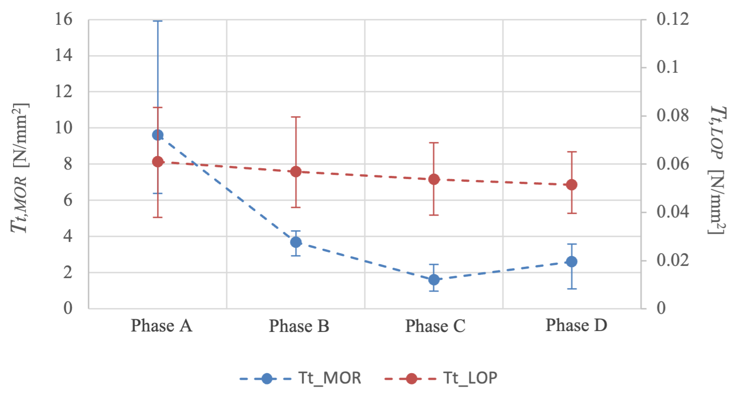
  • The flexural toughness at the Limit of Proportionality remains unaltered throughout the printing process, while the tensile toughness displays a small and steady decrease of up to 10% over the full printing process.
  • The flexural and tensile toughness at the Modulus Of Rupture present the clearest values for analysing the reduced mechanical performance, with respective overall reductions of 82 and 83% and with T f , M O R and T t , M O R displaying the most significant drops directly after pumping, at 61% and 62%, respectively
  • Among the four investigated phases, it can be concluded that the pumping phase has the most significant influence on the mechanical properties of 3PD-SHCC.
To determine the exact cause of the decrease in deformation capacity of 3DP-SHCC and how this can be overcome, further investigation of the microstructure and hydration products of the composite after the subsequent printing phases is recommended.

Author Contributions

A.L.v.O.: conceptualization, data curation, formal analysis, investigation, methodology, software, visualization, writing—original draft, writing—review and editing. B.Š.: methodology, writing—review and editing, supervision. F.P.B.: funding acquisition, resources, supervision, writing—review and editing. E.S.: writing—review and editing, supervision, resources. All authors have read and agreed to the published version of the manuscript.

Funding

This research was funded through NWO Open Technology Program, project ‘High Performance 3D Concrete Printing’, grant number 17251.

Data Availability Statement

Data will be made available on request.

Acknowledgments

Special thanks go out to Karsten Nefs for his assistance during the printing session at TU/e.

Conflicts of Interest

The authors declare no conflict of interest.

References

  1. Bos, F.; Menna, C.; Pradena, M.; Kreiger, E.; da Silva, W.L.; Rehman, A.; Weger, D.; Wolfs, R.; Zhang, Y.; Ferrara, L.; et al. The realities of additively manufactured concrete structures in practice. Cem. Concr. Res. 2022, 156, 106746. [Google Scholar] [CrossRef]
  2. Asprone, D.; Menna, C.; Bos, F.P.; Salet, T.A.; Mata-Falcón, J.; Kaufmann, W. Rethinking reinforcement for digital fabrication with concrete. Cem. Concr. Res. 2018, 112, 111–121. [Google Scholar] [CrossRef]
  3. Wangler, T.; Lloret, E.; Reiter, L.; Hack, N.; Gramazio, F.; Kohler, M.; Bernhard, M.; Dillenburger, B.; Buchli, J.; Roussel, N.; et al. Digital concrete: Opportunities and challenges. RILEM Tech. Lett. 2016, 1, 67–75. [Google Scholar] [CrossRef]
  4. Buswell, R.A.; de Silva, W.L.; Jones, S.; Dirrenberger, J. 3D printing using concrete extrusion: A roadmap for research. Cem. Concr. Res. 2018, 112, 37–49. [Google Scholar] [CrossRef]
  5. Hass, L.; Bos, F.; Salet, T. Characterizing the bond properties of automatically placed helical reinforcement in 3D printed concrete. Constr. Build. Mater. 2022, 355, 129228. [Google Scholar] [CrossRef]
  6. Hass, L.; Nefs, K.; Bos, F.; Salet, T. Application potential of combining strain hardening cementitious composites and helical reinforcement for 3D concrete printed structures: Case study of a spiral staircase. J. Build. Eng. 2023. under review. [Google Scholar]
  7. Li, V. Engineered Cementitious Composites (ECC); Springer: Berlin/Heidelberg, Germany, 2019. [Google Scholar]
  8. Bao, Y.; Xu, M.; Soltan, D.; Xia, T.; Shih, A.; Clack, H.L.; Li, V.C. Three-Dimensional Printing Multifunctional Engineered Cementitious Composites (ECC) for Structural Elements. In Proceedings of the RILEM International Conference on Concrete and Digital Fabrication, Zurich, Switzerland, 10–12 September 2018; Springer: Berlin/Heidelberg, Germany, 2018; pp. 115–128. [Google Scholar]
  9. Figueiredo, S.C.; Rodriguez, C.R.; Ahmed, Z.Y.; Bos, D.H.; Xu, Y.; Salet, T.M.; Çopuroğlu, O.; Schlangen, E.; Bos, F.P. An approach to develop printable strain hardening cementitious composites. Mater. Des. 2019, 169, 107651. [Google Scholar] [CrossRef]
  10. Ogura, H.; Nerella, V.; Mechtcherine, V. Developing and testing of strain-hardening cement-based composites (SHCC) in the context of 3D-printing. Materials 2018, 11, 1375. [Google Scholar] [CrossRef]
  11. van Overmeir, A.L.; Figueiredo, S.C.; Šavija, B.; Bos, F.P.; Schlangen, E. Design and analyses of printable strain hardening cementitious composites with optimized particle size distribution. Constr. Build. Mater. 2022, 324, 126411. [Google Scholar] [CrossRef]
  12. Li, V.C.; Bos, F.P.; Yu, K.; McGee, W.; Ng, T.Y.; Figueiredo, S.C.; Nefs, K.; Mechtcherine, V.; Nerella, V.N.; Pan, J.; et al. On the emergence of 3D printable engineered, strain hardening cementitious composites (ECC/SHCC). Cem. Concr. Res. 2020, 132, 106038. [Google Scholar] [CrossRef]
  13. Sikora, P.; Techman, M.; Federowicz, K.; El-Khayatt, A.M.; Saudi, H.; Abd Elrahman, M.; Hoffmann, M.; Stephan, D.; Chung, S.Y. Insight into the microstructural and durability characteristics of 3D printed concrete: Cast versus printed specimens. Case Stud. Constr. Mater. 2022, 17, e01320. [Google Scholar] [CrossRef]
  14. Le, T.; Austin, S.; Lim, S.; Buswell, R.; Law, R.; Gibb, A.; Thorpe, T. Hardened properties of high-performance printing concrete. Cem. Concr. Res. 2012, 42, 558–566. [Google Scholar] [CrossRef]
  15. Wolfs, R.; Bos, F.; Salet, T. Hardened properties of 3D printed concrete: The influence of process parameters on interlayer adhesion. Cem. Concr. Res. 2019, 119, 132–140. [Google Scholar] [CrossRef]
  16. Marchment, T.; Sanjayan, J. Mesh reinforcing method for 3D Concrete Printing. Autom. Constr. 2020, 109, 102992. [Google Scholar] [CrossRef]
  17. Seo, E.A.; Kim, W.W.; Kim, S.W.; Kwon, H.K.; Lee, H.J. Mechanical properties of 3D printed concrete with coarse aggregates and polypropylene fiber in the air and underwater environment. Constr. Build. Mater. 2023, 378, 131184. [Google Scholar] [CrossRef]
  18. Woo, S.J.; Yang, J.M.; Lee, H.J.; Kwon, H.K. Comparison of Properties of 3D-Printed Mortar in Air vs. Underwater. Materials 2021, 14, 5888. [Google Scholar] [CrossRef]
  19. van Overmeir, A.L.; Šavija, B.; Bos, F.P.; Schlangen, E. 3D Printable Strain Hardening Cementitious Composites (3DP-SHCC), tailoring fresh and hardened state properties. Constr. Build. Mater. 2023, 11, 132924. [Google Scholar] [CrossRef]
  20. Zhou, W.; Zhang, Y.; Ma, L.; Li, V. Influence of printing parameters on 3D printing engineered cementitious composites (3DP-ECC). Cem. Concr. Compos. 2022, 130, 104562. [Google Scholar] [CrossRef]
  21. Chaves Figueiredo, S.; Romero Rodriguez, C.; Ahmed, Z.; Bos, D.; Xu, Y.; Salet, T.; Çopuroğlu, O.; Schlangen, E.; Bos, F. Mechanical Behavior of Printed Strain Hardening Cementitious Composites. Materials 2020, 13, 2253. [Google Scholar] [CrossRef]
  22. Li, V.C. On engineered cementitious composites (ECC). J. Adv. Concr. Technol. 2003, 1, 215–230. [Google Scholar] [CrossRef]
  23. Li, J.; Qiu, J.; He, S.; Yang, E.H. Micromechanics-based design of strain hardening cementitious composites (SHCC). In Proceedings of the International Conference on Strain-Hardening Cement-Based Composites, Dresden, Germany, 18–20 September 2017; Springer: Berlin/Heidelberg, Germany, 2017; pp. 12–27. [Google Scholar]
  24. Ragalwar, K.; Heard, W.F.; Williams, B.A.; Ranade, R. Significance of the particle size distribution modulus for strain-hardening-ultra-high performance concrete (SH-UHPC) matrix design. Constr. Build. Mater. 2020, 234, 117423. [Google Scholar] [CrossRef]
  25. Li, M.; Li, V.C. Rheology, fiber dispersion, and robust properties of Engineered Cementitious Composites. Mater. Struct. 2013, 46, 405–420. [Google Scholar] [CrossRef]
  26. Kim, J.K.; Kim, J.S.; Ha, G.J.; Kim, Y.Y. Tensile and fiber dispersion performance of ECC (engineered cementitious composites) produced with ground granulated blast furnace slag. Cem. Concr. Res. 2007, 37, 1096–1105. [Google Scholar] [CrossRef]
  27. Tay, Y.W.D.; Ting, G.H.A.; Qian, Y.; Panda, B.; He, L.; Tan, M.J. Time gap effect on bond strength of 3D-printed concrete. Virtual Phys. Prototyp. 2019, 14, 104–113. [Google Scholar] [CrossRef]
  28. Panda, B.; Mohamed, N.A.N.; Tay, Y.W.D.; Tan, M.J. Bond Strength in 3D Printed Geopolymer Mortar. In Proceedings of the RILEM International Conference on Concrete and Digital Fabrication, Zurich, Switzerland, 10–12 September 2018; Springer: Berlin/Heidelberg, Germany, 2018; pp. 200–206. [Google Scholar]
  29. Sanjayan, J.G.; Nematollahi, B.; Xia, M.; Marchment, T. Effect of surface moisture on inter-layer strength of 3D printed concrete. Constr. Build. Mater. 2018, 172, 468–475. [Google Scholar] [CrossRef]
  30. Panda, B.; Noor Mohamed, N.A.; Paul, S.C.; Bhagath Singh, G.; Tan, M.J.; Šavija, B. The Effect of Material Fresh Properties and Process Parameters on Buildability and Interlayer Adhesion of 3D Printed Concrete. Materials 2019, 12, 2149. [Google Scholar] [CrossRef] [PubMed]
  31. Roussel, N.; Cussigh, F. Distinct-layer casting of SCC: The mechanical consequences of thixotropy. Cem. Concr. Res. 2008, 38, 624–632. [Google Scholar] [CrossRef]
  32. Chaves Figueiredo, S.; van Overmeir, A.L.; Nefs, K.; Schlangen, E.; Salet, T.A.; Šavija, B.; Suiker, A.S.; Bos, F.P. Quality Assessment of Printable Strain Hardening Cementitious Composites Manufactured in Two Different Printing Facilities. In Proceedings of the Second RILEM International Conference on Concrete and Digital Fabrication, Eindhoven, The Netherlands, 6–8 July 2020; Springer International Publishing: Berlin/Heidelberg, Germany, 2020; pp. 824–838. [Google Scholar]
  33. Li, F.; Shen, W.; Yuan, Q.; Hu, X.; Li, Z.; Shi, C. An overview on the effect of pumping on concrete properties. Cem. Concr. Compos. 2022, 129, 104501. [Google Scholar] [CrossRef]
  34. Jang, K.; Kwon, S.; Choi, M. Experimental Observation on Variation of Rheological Properties during Concrete Pumping. Int. J. Concr. Struct. Mater. 2018, 12, 79. [Google Scholar] [CrossRef]
  35. Shen, W.; Yuan, Q.; Shi, C.; Ji, Y.; Zeng, R.; Li, W.; Chen, Z. Influence of pumping on the resistivity evolution of high-strength concrete and its relation to the rheology. Constr. Build. Mater. 2021, 302, 124095. [Google Scholar] [CrossRef]
  36. Hambach, M.; Rutzen, M.; Volkmer, D. Properties of 3D-printed fiber-reinforced Portland cement paste. In 3D Concrete Printing Technology; Elsevier: Amsterdam, The Netherlands, 2019; pp. 73–113. [Google Scholar]
  37. Ma, G.; Li, Z.; Wang, L.; Wang, F.; Sanjayan, J. Mechanical anisotropy of aligned fiber reinforced composite for extrusion-based 3D printing. Constr. Build. Mater. 2019, 202, 770–783. [Google Scholar] [CrossRef]
  38. Chen, M.; Yang, L.; Zheng, Y.; Li, L.; Wang, S.; Huang, Y.; Zhao, P.; Lu, L.; Cheng, X. Rheological behaviors and structure build-up of 3D printed polypropylene and polyvinyl alcohol fiber-reinforced calcium sulphoaluminate cement composites. J. Mater. Res. Technol. 2021, 10, 1402–1414. [Google Scholar] [CrossRef]
  39. Xu, N.; Qian, Y. Effects of fiber volume fraction, fiber length, water-binder ratio, and nanoclay addition on the 3D printability of strain-hardening cementitious composites (SHCC). Cem. Concr. Compos. 2023, 139, 105066. [Google Scholar] [CrossRef]
  40. Alamshahi, V.; Taeb, A.; Ghaffarzadeh, R.; Rezaee, M.A. Effect of composition and length of PP and polyester fibres on mechanical properties of cement based composites. Constr. Build. Mater. 2012, 36, 534–537. [Google Scholar] [CrossRef]
  41. Bos, F.; Wolfs, R.; Ahmed, Z.; Salet, T. Additive manufacturing of concrete in construction: Potentials and challenges of 3D concrete printing. Virtual Phys. Prototyp. 2016, 11, 209–225. [Google Scholar] [CrossRef]
  42. M-Tec. Available online: https://m-tec.com/connect/p20-connect/ (accessed on 10 August 2021).
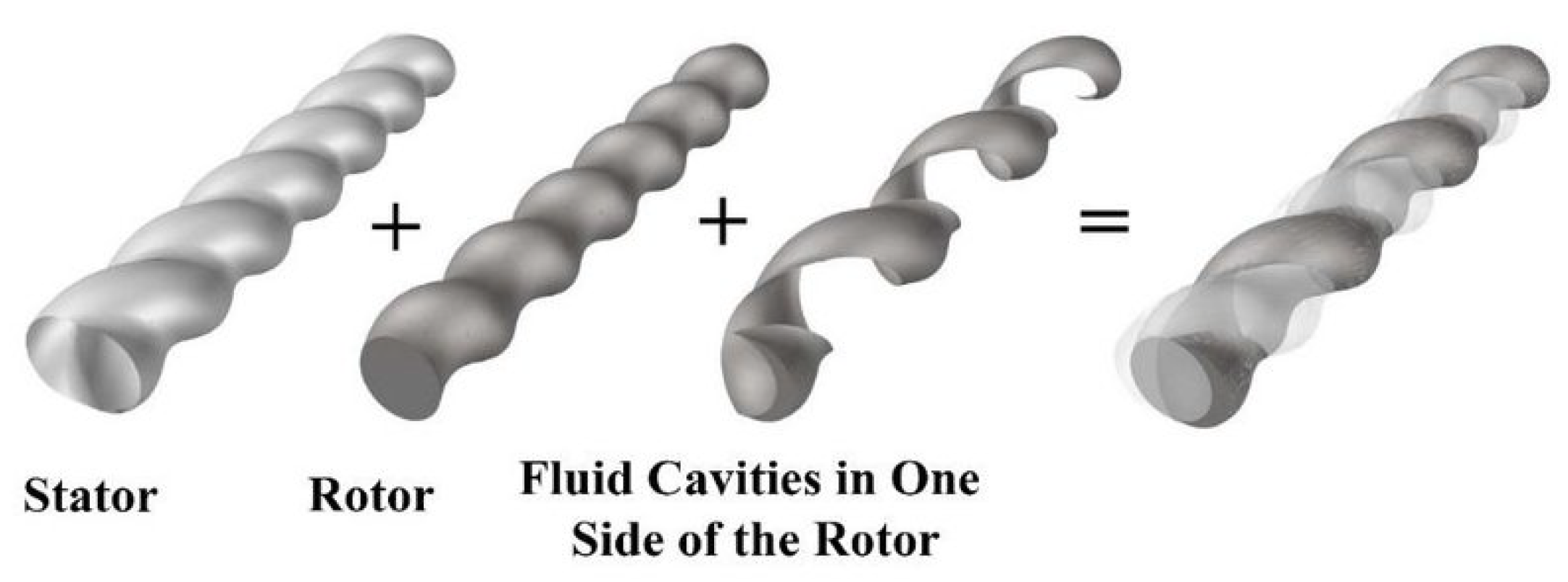
  43. D8-2 Rotor-Stator. Available online: https://www.putzparts24.com/de/collections/rotors-1/products/rotor-d8-2 (accessed on 19 August 2021).
  44. Aql, A. Dimensional and Empirical Modeling of Fluid Flow in Progressing Cavity Pumps. Master’s Thesis, Kuwait University, Kuwait City, Kuwait, 2016. Available online: https://www.researchgate.net/publication/324175995-Dimensional-and-Empirical-Modeling-of-Fluid-Flow-in-Progressing-Cavity-Pumps (accessed on 3 September 2023).
  45. Mechtcherine, V.; Van Tittelboom, K.; Kazemian, A.; Kreiger, E.; Nematollahi, B.; Nerella, V.N.; Santhanam, M.; De Schutter, G.; Van Zijl, G.; Lowke, D.; et al. A roadmap for quality control of hardening and hardened printed concrete. Cem. Concr. Res. 2022, 157, 106800. [Google Scholar]
  46. Kim, D.; Naaman, A.; El-Tawil, S. Comparative flexural behavior of four fiber reinforced cementitious composites. Cem. Concr. Compos. 2008, 30, 917–928. [Google Scholar] [CrossRef]
  47. Turk, K.; Nehdi, M. Flexural toughness of sustainable ECC with high-volume substitution of cement and silica sand. Constr. Build. Mater. 2021, 270, 121438. [Google Scholar] [CrossRef]
  48. van Overmeir, A.L. Designing an Interlayer Reinforcement Solution for Printable Strain-Hardening Cement-Based Composites. Master’s Thesis, Delft University of Technology, Delft, The Netherlands, 2020. [Google Scholar]
  49. Soltan, D.G.; Li, V.C. A self-reinforced cementitious composite for building-scale 3D printing. Cem. Concr. Compos. 2018, 90, 1–13. [Google Scholar]
  50. Secrieru, E.; Cotardo, D.; Mechtcherine, V.; Lohaus, L.; Schröfl, C.; Begemann, C. Changes in concrete properties during pumping and formation of lubricating material under pressure. Cem. Concr. Res. 2018, 108, 129–139. [Google Scholar] [CrossRef]
  51. Gallucci, E.; Zhang, X.; Scrivener, K. Effect of temperature on the microstructure of calcium silicate hydrate (C-S-H). Cem. Concr. Res. 2013, 53, 185–195. [Google Scholar] [CrossRef]
  52. Lothenbach, B.; Winnefeld, F.; Alder, C.; Wieland, E.; Lunk, P. Effect of temperature on the pore solution, microstructure and hydration products of Portland cement pastes. Cem. Concr. Res. 2007, 37, 483–491. [Google Scholar] [CrossRef]
Figure 1. Progressive cavity pump with its specific attributes: (a) M-Tec P-20 connect [42] (b) Type D8-2 rotor/stator [43]; (c) Archimedes transport screw.
Buildings 13 02483 g001
Figure 2. 3D configuration of pump rotor, stator, and fluid cavities on one side of the rotor [44].
Buildings 13 02483 g002
Figure 3. Four-point bending test setup, with measurements in mm [19].
Buildings 13 02483 g003
Figure 4. Flexural toughness: (a) Theory [19] (b) LOP and MOR data points of multiple specimens.
Buildings 13 02483 g004
Figure 5. Test setup for the uniaxial tensile test, with measurements in mm, adapted from [11].
Buildings 13 02483 g005
Figure 6. Compressive strength for specimens from printing phases A, B, C, and D.
Buildings 13 02483 g006
Figure 7. Apparent density for specimens from printing phases A, B, C, and D.
Buildings 13 02483 g007
Figure 8. Flexural stress–deflection curves for printing phases A, B, C, and D at 28 days.
Buildings 13 02483 g008
Figure 9. Development of flexural toughness over the four printing phases.
Buildings 13 02483 g009
Figure 10. Tensile stress–strain curves: (a) Phase A, (b) Phase B, (c) Phase C, (d) Phase D.
Buildings 13 02483 g010
Figure 11. Development of tensile toughness over the four printing phases.
Buildings 13 02483 g011
Table 1. 3DP-SHCC composition in kg/m 3 .
 BFSCEM ISFLSSandWaterPVAVMASP
42.5 N vol%
Mix D2634703358431840023.062.68
Table 2. Specifications of RECS15 PVA fibres.
  RECS15
Tensile strengthMPa1600
Modulus of elasticityGPa41
Ultimate strain%6
Lengthmm8
Diameterμm40
Aspect ratioL/D200
Densitykg/m31.3
Table 3. Averaged results of the four-point bending tests with standard deviations.
Flexural Stress at LOPDeflection at LOPMaximum Flexural StressDeflection at Max. Flexural Stress
[MPa]STD[mm]STD[MPa]STD[mm]STD
Phase A3.99±0.650.26±0.059.02±0.8111.91±1.25
Phase B3.94±0.840.31±0.066.62±0.875.48±0.83
Phase C4.06±0.350.28±0.036.62±1.254.62±1.01
Phase D3.89±0.290.31±0.186.03±1.012.63±1.26
Table 4. Average results of the uniaxial tensile test with standard deviations.
Tensile Stress at LOPTensile Strain at LOPMaximum Tensile StressStrain at Max. Tensile Stress
MPaSTD%STDMPaSTD%STD
Phase A2.61±0.080.039±0.0093.390.403.051±1.166
Phase B2.26±0.270.051±0.0412.88±0.160.870±0.411
Phase C1.83±0.240.042±0.0072.20±0.090.580±0.294
Phase D2.27±0.160.040±0.0132.58±0.120.898±0.534
Disclaimer/Publisher’s Note: The statements, opinions and data contained in all publications are solely those of the individual author(s) and contributor(s) and not of MDPI and/or the editor(s). MDPI and/or the editor(s) disclaim responsibility for any injury to people or property resulting from any ideas, methods, instructions or products referred to in the content.

