Technical Note

Development of a New Uplift Pile with Prestressed Semi-Bonded Composite Anchor

1
State Key Laboratory of Hydroscience and Engineering, Department of Hydraulic Engineering, Tsinghua University, Beijing 100084, China
2
China Building Technique Group Co., Ltd., Beijing 100013, China
3
Key Laboratory of Urban Underground Engineering of Ministry of Education, Beijing Jiaotong University, Beijing 100044, China
*
Author to whom correspondence should be addressed.
Buildings 2022, 12(9), 1478; https://doi.org/10.3390/buildings12091478
Submission received: 17 July 2022 / Revised: 26 August 2022 / Accepted: 9 September 2022 / Published: 17 September 2022
(This article belongs to the Special Issue Advances in Soils and Foundations)

Abstract

:
This paper introduces a new type of prestressed uplift pile that adopts the semi-bonded composite anchor as the main reinforcement. An in-situ experimental study was carried out to investigate the new pile’s deformation, stress, bearing capacity, and cracking characteristics, which were then compared with the conventional piles. Results show that although the reinforcement ratio of the new pile is only 0.75%, much less than that of the conventional pile (i.e., 3.84%), it achieves similar or even better mechanical properties under uplift loads. The cost of the pile’s anchorage system is reduced by 43.8%, and the total cost of a single pile is reduced by 33.6%. Compared with the conventional pile, the new pile makes better use of the lateral friction resistance of the lower pile body, and the uplift bearing capacity and the uplift resistance of the pile are improved correspondingly. In addition, the cracking resistance of the new pile is significantly improved, with the cracking load increased by 88.2% and the cracking area reduced by 48.3%. In addition, the multi-layer structure of the composite main bar provides better protection for the load-bearing steel strands against corrosion. As such, the new type of pile is expected to gain much better durability than the conventional ones.

1. Introduction

With the development of social economy and construction technology, high-rise and super high-rise buildings are becoming more common. The utilization of urban above-ground space has basically reached a state of saturation [1]. In recent years, the expansion of underground space has become mainstream [2]. With the development of underground engineering to a deeper level, cases of floating damage to buildings have occurred repeatedly due to the uplift forces of underground water and natural disasters [3,4,5,6]. Therefore, the topic of building anti-floating has become one of the focuses of civil engineering.
Anti-floating in civil engineering usually adopts passive anti-uplift methods, such as setting anchor rods and piles [7,8,9,10]. However, the anchor rods usually provide relatively small uplift resistance. They are mainly used for secondary anti-floating reinforcement of buildings or structures that are less affected by the buoyancy of groundwater. For buildings with large raft foundations, the uplift resistance provided by rods is usually insufficient. In this case, the large-sized uplift pile (e.g., with a diameter D ≥ 800 mm) that can provide much higher uplift resistance is a more effective measure and has been commonly used in buildings that are relatively significantly affected by groundwater buoyancy.
For conventional reinforced concrete uplift piles, the main reinforcement is wrapped by the outer layer of concrete and isolated from the external environment (e.g., groundwater). However, the uplift pile is a tensile component, which can be easily cracked under tension [11,12]. Furthermore, in many areas (e.g., coastal areas), the groundwater level is high and contains high concentrations of ions (e.g., chloride and sulfate ions). These ions are highly corrosive to the steel bars, and they can easily penetrate the pile body through the concrete cracks to corrode the steel bars and even make the uplift piles ineffective [13,14]. In order to solve the problems of crack resistance and durability of conventional uplift piles, more steel bars were configured, leading to significant increases in the pile’s reinforcement ratio. However, the vertical uplift bearing capacity of the pile and the tensile strength of the main reinforcement cannot be fully exerted, which is a waste of steel bars. At present, reducing the cost of uplift piles, decreasing the waste of main reinforcements, and improving the durability and safety of piles are still the focuses of current research.
At present, scholars have carried out a lot of research on the anti-floating of underground structures. They studied the anti-floating anchors and anti-uplift piles from the aspects of theoretical analysis, numerical simulation, field tests, and engineering applications. In addition, new technologies, such as prestressing [15], expanding bottom piles [16,17], and post-grouting, are integrated into the anti-floating methods. For example, Wang et al. [18] proposed a new method for calculating the bearing capacity of two-way crimped uplift piles. Yang and Zou [8] studied the relationship between pile side friction and shear displacement theoretically, and compared the experimental results with the calculated values. Zheng and Zhuge [19] analyzed the deformation and stress characteristics of expanded bottom piles and post-grouting piles through field tests. With the advancement of mechanical mechanism analyses and numerical simulation methods, scholars also carried out more targeted in-situ experimental studies on uplift piles. Krabbenhoft et al. [20] performed static load tests of 30 bored cast-in-place uplift piles with different diameters (i.e., 14 and 25 cm) and discussed the factors affecting the pile’s uplift bearing capacities, such as pile diameter, grain size of sand, and lateral pressure coefficient of soil. Zhang et al. [21] conducted two sets of static load tests on full-scale uplift piles and analyzed the mechanisms of load transfer and ultimate bearing capacity of the piles. In summary, current studies on uplift piles mainly focus on the interpretation of mechanisms of stress and displacement and improving the lateral friction resistance and ultimate bearing capacity [22,23,24].
In this study, a new type of prestressed uplift pile with semi-bonded composite anchors as the main reinforcement was developed, aiming to optimize the pile design, reduce the cost, and improve its performance and durability. A total of nine full-scale in-situ static load tests were carried out to investigate the essential characteristics of the new pile and the conventional reinforced concrete pile. Then, based on the experimental results, the efficiency and the load transfer mechanism of the new, prestressed, semi-bonded composite-anchor pile and the conventional pile were discussed and compared.

2. Materials and Methods

2.1. Description of the Experimental Site

The experimental site is located in Tongzhou District, Beijing, which was selected mainly because of its flat terrain and simple and evenly distributed soil layers. Basically, the stratum of the site consists of an upper sandy silt layer with a thickness of 2.5 m and a bottom fine sand layer. The simple and flat soil layer ensures the consistency of foundation properties at different test piles, which is beneficial to exclude the influence of varying soil properties on the ultimate uplift-bearing capacity of piles, thus ensuring the reliability of the results of parallel and comparative tests. The ground elevation of the experimental site is 24.0 m, and the designed elevation of the pile top is 19.50 m.

2.2. Design of Test Piles

In this study, three different kinds of uplift piles were built in this experimental site: (a) the newly developed semi-bonded prestressed uplift pile using mud rotary drilling (i.e., KB2-type); (b) the semi-bonded prestressed uplift pile using dry rotary drilling (i.e., KB7-type); and (c) the conventional reinforced concrete uplift pile using mud rotary drilling (i.e., KB1-type).
Developing the new prestressed anchor-cable pile is mainly based on two aspects of concern. On the one hand, the uplift pile is one of the main forms of foundation, which has been widely used in recent years in both the construction of tall buildings and underground structures with anti-floating requirements. On the other hand, however, there are still many deficiencies in traditional uplift piles, such as excessive reinforcements, high construction costs, and easy cracking. As such, a completely new design of uplift pile was proposed here, aiming to replace the traditional piles in future engineering projects. The conventional pile was originally designed as a benchmark for comparison with the new types of piles.
The piles have a diameter of 800 mm and an effective length of 22.0 m (i.e., the elevations of the pile top and bottom are 19.50 m and −2.50 m, respectively). In practical engineering applications, a typical size of an uplift pile with a diameter of 800 mm can usually meet the design requirements of general infrastructure buildings. In addition, according to the classification in “Technical Code for Testing of Building Pile Foundations” (JGJ 94-2008) [25], uplift piles with a diameter of 800 mm and above are regulated as large-diameter piles. This study selects this size (i.e., 800 mm in diameter) as a representative to investigate the mechanical properties of pullout resistance in practical engineering, which can not only better reflect the mechanical properties of large-diameter piles commonly used in engineering, but also reduce test costs and resource consumption. The C35 concrete was used for pile construction. The estimated uplift bearing capacity of the piles (i.e., KB-1, KB-2, and KB-7) are 4400, 4600, and 4800 kN, respectively. More detailed information on the piles can be found in Table 1. To ensure the reliability of experimental results, three repeated tests were carried out for each pile type.

2.2.1. Prestressed Uplift Pile with Semi-Bonded Composite Anchor

A new type of semi-bonded prestressed uplift pile with composite anchors was developed in this study. The new pile has a diameter of 800 mm, with the thickness of the concrete protective layer of 70 mm. The reinforcement cage has a diameter of 660 mm and adopts four semi-bonded composite anchor cables as the main reinforcement, as shown in Figure 1a.
Like the conventional reinforced concrete pile, the stiffener ring adopts the 20 mm-diameter HRB400 steel bars, arranged with a spacing of 2 m, and the outer spiral stirrups adopt the 8 mm-diameter HPB300 steel bars that are arranged with a spacing of 200 mm. As shown in Figure 2a, in order to ensure that the head of pile does not crack while applying prestress, within 3 m below the pile top, the spacing of stiffener rings is densified to 1 m, and the spacing of spiral stirrups is densified to 80 mm. In addition, a steel casting with a height of 700 mm and a thickness of 5 mm is welded on the top of the steel cage. The upper part of the composite anchor with a length of 160 mm is partially sleeve welded with the spiral reinforcements (i.e., 10 mm-diameter HPB300 steel bar at the pitch of 40 mm). Moreover, two auxiliary bars (25 mm-diameter HRB400 bars) and two acoustic measuring tubes are arranged at equal intervals at the same radius of the main bars.
Again, the new pile adopts the composite anchor cable as the main reinforcement. As shown in Figure 2, the composite anchor cable is composed of 3 steel strands with a diameter Φs of 21.8 mm, a high-strength steel pipe, and a certain amount of high-strength non-expansion grout. The inner diameter of the high-strength steel pipe is 65 mm, with a wall thickness of 3.5 to 4.0 mm. The bottom ends of the high-strength steel pipes were closed by welding. It should be specially pointed out that to optimize the stress state of the pile, the steel strands in the upper half of the composite anchor cable are greased and covered with a plastic sheath to isolate the strands from the non-expanding high-strength grout. In this way, a semi-bonded composite anchor cable is formed. The cross-sections of composite anchor cable in the upper and lower half are shown in Figure 2b,c, respectively.

2.2.2. Conventional Reinforced Concrete Pile as the Benchmark

The diameter of the conventional reinforced concrete uplift pile (KB-1) is 800 mm, the thickness of the concrete protective layer is 70 mm, and the diameter of the reinforcement cage is 660 mm. Twenty-four HRB400 steel bars with a diameter of 32 mm are used as the main reinforcement, as shown in Figure 1b. In addition, two acoustic tubes are symmetrically arranged in the pile cage to inspect the pile integrity after the completion of pile building. An HRB400 steel bar with a diameter of 25 mm is arranged inside the steel cage as a structural bar for lapping optical fibers. The stiffener rings adopt the 20 mm-diameter HRB400 steel bars, and they are arranged with a spacing of 2 m. The outer spiral stirrups adopt the 8 mm-diameter HPB300 steel bars and are arranged with a spacing of 200 mm.

2.3. Construction Technology of New Uplift Pile

2.3.1. Pile Cage Fabrication and Sensor Placement

When making the pile cage of the new uplift pile, the high-strength steel pipes were first connected and welded to the designed length, in accordance with the “Code for Welding of Steel Structures” (GB 50661-2011) [26]. Then, the high-strength steel pipe was welded with stiffened stirrups. Finally, the outer spiral stirrups were spot-welded to the steel pipes. In this study, the welding of steel bars was carried out according to the “Specification for Welding and Acceptance of Reinforcing Steel Bars” (JGJ 18-2012) [27]. After welding, each steel pipe is subjected to a water pressure test to ensure that the steel tube is leak-proof. At the completion of the steel cage, the pile top was covered with steel casing, with the top of steel pipes locally reinforced with spiral bars. The top opening of the steel pipe is sealed with a plug and then wrapped with a layer of adhesive tape to prevent concrete from entering the steel pipe during the piling process.
In addition, during the fabrication of the pile cage, the rebar meters and optical fiber were installed. Since the pile with dry rotary drilling uses the pile cage post-insertion method, the optical fiber can be easily scraped and broken by the concrete and thus lose its function, so optical fibers are only used in the pile with mud rotary drilling.
In this study, rebar stress meters were used to measure the internal stress of piles. In the pile, a total of 6 sections (i.e., the sections with distances of −1 m, −4 m, −7.5 m, −14 m, −18 m, and −21.5 m from the pile top, respectively) were selected to install the rebar meters, and on each section, three rebar stress meters were arranged at equal intervals along the circumferential direction. For the KB1 pile, the rebar meters were connected to the main bars by bar welding, with the length of double-sided welding greater than 5d (d is the diameter of main bar). For the KB2 and KB7 piles, the rebar meters were installed in the high-strength steel pipe by lap welding, with a welding length of greater than 10 cm.
In the conventional uplift pile (KB1), an optical fiber for measuring the distribution of cracks in the pile body was set up. To place the optical fiber, a structural bar was first welded inside the pile cage. Then, the fiber was laid along the structural bar and bundled every 1 m with the binding tape to keep the fiber straight against the structural bar without loosening. In the new uplift pile (KB2), the optical fiber was arranged along the auxiliary bars on the pile cage. In order to systematically reveal the strain behavior of the pile body, and to ensure the survival of the fiber and the reliability of the data, a U-shaped double-laying scheme was adopted, i.e., the optical fibers were wound half-circle at the bottom of the pile cage and distributed symmetrically along the auxiliary bars.

2.3.2. Hole-Forming and Grouting of Test Piles

The KB1 and KB2 type uplift piles use the method of mud rotary drilling. During construction, a rotary drilling rig is used to drill to the designed elevation, with the thickness of debris deposited at the hole bottom less than 15 cm. The hole-forming process needs to be completed continuously at one time. After completing the hole, the pile cage was hoisted into the hole for subsequent concrete pouring. C35 concrete was used for pile construction. In the initial stage of grouting, the conduit is inserted into the hole, with the distance between the conduit mouth and the bottom of the hole being 0.3–0.5 m. During the pouring process, the conduit is lifted up with the increase of concrete pouring amount until completion. The KB7-type uplift piles use the method of dry rotary drilling. After the drilling rig drills to the designed elevation, concrete is injected into the hole through the hollow drill pipe with pump pressure, and the drill pipe is gradually lifted while pouring concrete until completion. Then, the pile cage is hoisted into the drilled hole and vibrated during the lowering process. When the cage reaches the designed elevation, the lowering of the cage can be stopped.

2.3.3. Strand Insertion and Prestressing

After the pile body is formed, the non-expansion slurry is poured into the high-strength steel pile. Then, the upper half of the strands are coated with grease and covered with plastic sheaths to prepare semi-bonded steel strands. Three semi-bounded strands are bundled together and inserted into the high-strength steel pipe after grouting.
After the steel strand is inserted and the grout and pile body concrete reach the designed strength, the strands are tensioned to apply prestress. The pretension applied to each composite anchor cable is 1200 kN. It should be noted that each composite anchor cable is repeatedly loaded twice. When loading for the first time, the locking piece will not be placed in the anchorage, and the tension will be removed after being loaded to 1200 kN to straighten the steel strands. When loading for the second time, a locking piece is placed in the anchorage to lock the prestress of the steel strand at 1200 kN.

2.4. In-Situ Load Test

The single-pile static load test is an in-situ experimental method that simulates the actual load of pile and observes the corresponding pile deformations in order to check whether the ultimate bearing capacity and deformation meet the design expectations. In the test, the supporting blocks built on both sides of the test pile were used to provide the uplifting force, which makes full use of the bearing capacity of the foundation around the test pile and will not affect the adjacent piles.
Figure 3 shows the experimental setup for the single-pile static load test. Single-pile static load tests were carried out in accordance with “Technical Code for Testing of Building Pile Foundations” (JGJ106-2014) [28] and “Technical Code for Building Pile Foundations” (JGJ94-2008) [25]. During the test, the lifting force of the jack placed on the top of the main beam is transmitted to the main bars of pile through the tension connections. The uplift displacement of the pile can be obtained by four displacement gauges installed on the pile head.
During the test, the load is applied in stages, with an equal increment in each stage. The load increment is taken as 1/10 of the estimated ultimate uplift bearing capacity, and the load of the first stage is taken as two times the increment. After the load is applied in each stage, the uplift displacement of the pile top is measured at 5, 15, 30, 45, and 60 min, and then every 30 min until the rate of uplift displacement measured at the pile top is less than 0.1 mm/h. At this moment, the pile is considered to reach a relatively stable state. Then, the load of the next stage is applied. The loading will be terminated in the following cases: (1) the uplift displacement of the pile under a certain load is greater than five times the displacement under the action of the previous load stage; (2) the cumulative uplift displacement of the pile exceeds 100 mm; and (3) the uplift load reaches 0.9 times the strength of steel bars.
The unloading process is also carried out in stages, with an equal load decrement twice that of the load increment in the loading process. In each stage, the load will be maintained for 1.0 h, with the displacement of the pile top measured at 15, 30, and 60 min. After unloading to zero, the residual displacement of the pile will also be measured.

3. Analyses of Results

3.1. Characteristics of U-δ Curves

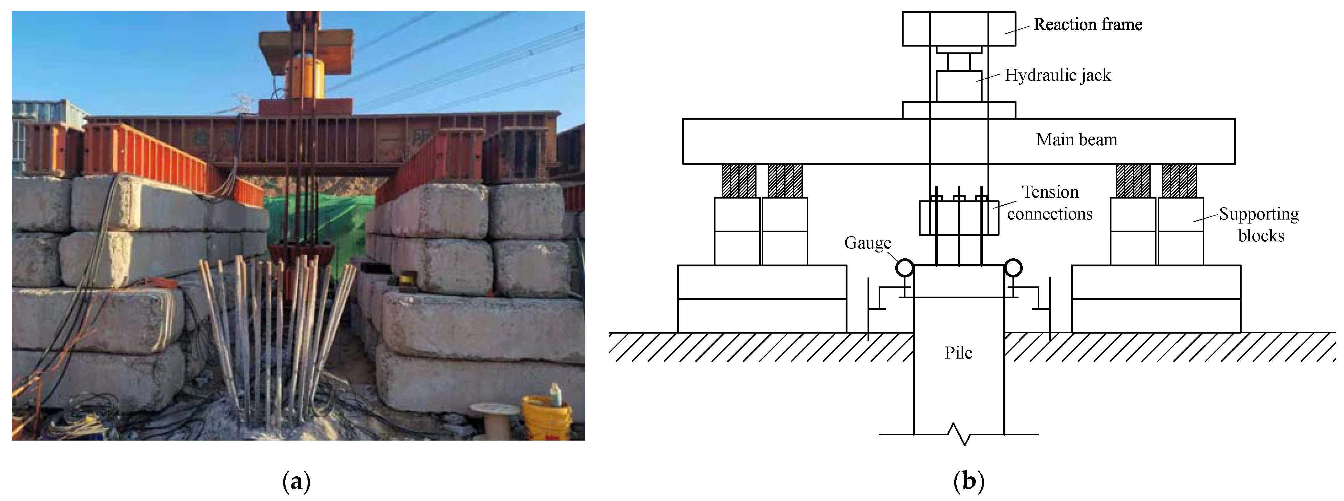
Figure 4 shows the experimental curves between the uplift load U and the displacement of pile top δ for different curves, and Figure 5 shows the time courses of δ in the semi-logarithmic coordinate. According to the U-δ curves, the uplift displacement of conventional piles (KB1) increases relatively slowly at the initial stage of loading. When the load increases to a certain level, the displacement increases suddenly, indicating a type of steep change. However, for the KB2 and KB7 piles, the uplift displacement increases slowly with the increasing load, showing a gradual change. According to the “Technical Specification for Testing of Building Foundation Piles” (JGJ106-2014), for the steeply deformed U-δ curve (e.g., KB1), the load corresponding to the beginning of the sudden increase in displacement is taken as the ultimate bearing capacity of pile. For the slowly deformed U-δ curves (e.g., KB2 and KB7), the load of the previous stage, where the slope of δ-lgt curve becomes steeper or the tail of the curve is obviously bent, can be taken as the pile’s ultimate bearing capacity. The experimental results of different piles are summarized in Table 2.
Comparing the U-δ curves of the KB1 type pile and KB2 type pile, when the load is less than the bearing capacity, the change rate of pile top displacement of the KB1 and KB2 piles is basically the same, and the pile top displacement increases relatively slowly. When the load exceeds the ultimate bearing capacity, the top displacement of the KB1-type pile increases sharply. According to the test results of piles (Table 2), the average uplift bearing capacity of the KB1 pile is 12.0% greater than that of the KB2 test pile, while the uplift displacement corresponding to the bearing capacity is 29.6% larger than that of the KB2 pile. From the U-δ curves, the vertical displacements of KB1 and KB2 type test piles under the same load have little difference, indicating that the uplift performance of the two types of piles is basically the same. On the whole, the uplift bearing capacity of both KB1 and KB2 piles reaches the estimated value and meets the design requirements.
Comparing the U-δ curves of KB1 and KB7 piles, at the initial loading stage, the vertical displacement of the two types of piles changes basically the same as the uplift load, and both show a linear trend. This distribution characteristic is mainly caused by the elastic deformation of the pile at the initial stage of loading. The load applied in the initial test stage was relatively small. Under the action of a small load, the interfaces between the main reinforcement and concrete and between the pile and soil did not reach the ultimate stress state. The displacement of the pile top will be mainly controlled by the elastic deformation of the pile-soil interface, so their displacements basically show a linear increase with a similar slope with the increase of the load. With the further increase of the load, the change rate of vertical displacement increases gradually, showing an upward concave. However, the change rate of vertical displacement of KB1 type pile is faster than that of KB7 type pile, and the U-δ curves of KB7 piles are always below that of KB1 piles. According to Table 2, the uplift bearing capacity of the KB7-type pile is similar to that of the KB1-type test pile, while its corresponding uplift displacement is much (about 7.4 mm) smaller than that of the KB1-type test pile. The KB7 type piles have better uplift performance than the KB1 type pile.
In addition, the U-δ curves of KB2 and KB7 piles have the same “slow change” characteristics. With the gradual increase of the load, the change rate of displacement of KB2 piles is greater than that of the KB7 pile. Under the load of 5520 kN, the vertical displacement of the KB7 type pile is about 55% of that of the KB2 type pile. According to the experimental results in Table 2, the averaged uplift bearing capacity of the KB7 pile is about 550 kN larger than that of the KB2 pile, and its corresponding uplift displacement is about 2.9 mm smaller than that of the KB2 pile. This is because the KB7 pile adopts the hole-forming method of dry rotary drilling, which avoids the mud skin effect between the pile body and the soil.
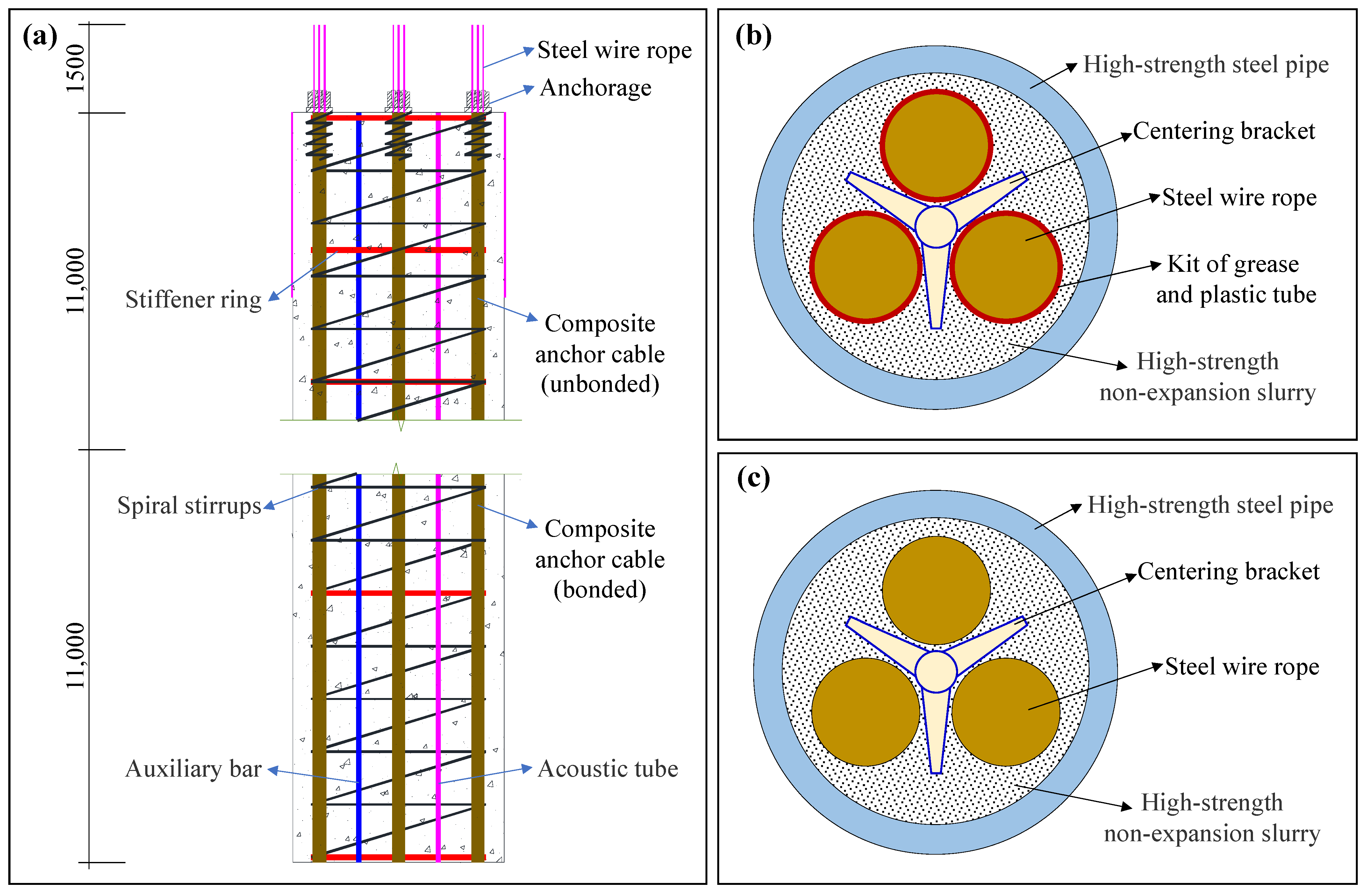
In summary, the uplift performance of the KB1 and KB2 piles is basically the same; due to the absence of mud skin effect in the KB7 pile, its displacement is smaller than that of KB1 and KB2 piles, with similar or greater ultimate bearing capacity. Both the conventional pile (e.g., KB1) and the new pile (e.g., KB2 and KB7) can meet the designed uplift bearing capacity. The new pile has only four composite anchors as the main reinforcement, with a reinforcement ratio of 0.75%, while the reinforcement ratio of the KB1 pile is 3.84%. That is, compared with the conventional pile, the reinforcement ratio of the new-type composite-anchor pile is reduced by 80.54%, and the cost of the pile cage is reduced by about 47%.

3.2. Distribution of Axial Forces

Figure 6 shows the distribution of axial force along the piles. Since the results of the repeated tests for each pile type are basically the same, only one set of test results is illustrated for each pile type. It can be seen from the figure that the axial force in the KB1 pile decreases gradually from top to bottom, and the pile body is basically in a tension state. For the KB2 and KB7 type piles, the upper part of the pile body is in a state of compression due to the application of prestress. In the initial stage of loading, the prestress gradually cancels out, and with the increase of the vertical load, the pressure on the upper part of the pile body gradually decreases, and the axial force in the tension zone in the lower part of the pile gradually increases. Generally, the stress in the lower middle part of the pile body is the greatest, and it decreases rapidly towards the pile top and the pile bottom.
Table 3 shows the distribution of the pile’s lateral friction resistance under a load of 5520 kN. Comparing the distribution of axial force and lateral friction between the conventional uplift pile and the new prestressed uplift pile with semi-bonded composite anchor, the stressed area of the former is mainly concentrated at the elevation from −1 to −4 m, while the latter is mainly at the elevation from −11 to −18 m. The maximum lateral friction resistance of the new pile is 2.5 times that of the conventional uplift pile. In addition, the lateral friction resistance of the new piles at the elevation from −11 to −18 m is about 10 times that of the conventional piles, and the lateral friction resistance of the new piles at the elevation from −18 to −21.5 m is about five times that of the conventional uplift piles.
Comparing the lateral friction resistance of KB2 and KB7 piles, the stressed positions are mainly concentrated in the lower middle part of the pile body. At the most stressed position (i.e., from −11 to −18 m), the lateral friction of the KB7 pile is 1.0–1.1 times that of the KB2 type pile; at the location from −1 to −11 m, the lateral friction of the KB7 pile is about 25% that of the KB2 pile; and at the location from −18 to −21.5 m, the lateral friction of KB7 pile is about 90% of that of KB2 pile. The differences in the lateral friction between the KB2 and KB7 piles are mainly caused by the different hole forming methods of the two.
In summary, the conventional pile (i.e., KB1) is mainly stressed at the upper part of the pile body, and the new piles (i.e., KB2 and KB7) are mainly stressed at the lower middle part. As we know, the soil pressure on the pile side increases with increasing burial depth, so the lateral friction resistance of the lower middle part of the new pile can be exerted more effectively, and the uplift bearing capacity and the uplift resistance of the pile can be improved correspondingly.

3.3. Cracking Characteristics of Test Piles

Figure 7 shows the strain distribution of the KB1 and KB2 piles, which reflect the development of microcracks in the pile during loading. From Figure 7a, it can be seen that no significant cracks appeared in the pile body of KB-1 during the first three loading stages throughout the loading process. With the increase in load, the pile strain gradually increases. Starting from the fourth loading stage (2200 kN), micro-cracks first start to appear in the area from 0 to 4 m at the top of the pile. As the load increases further, the cracking area gradually expands to the lower part of the pile body. When the pile is loaded to the maximum stage, the cracking area develops to a large range of 0–14.5 m from the top of the pile.
On the other hand, Figure 7b shows the strain distribution of the KB2 pile throughout the loading process. No significant cracks were observed in the pile for the first seven loading stages. Similarly, the pile strain gradually increases with the increase of load. From the eighth loading stage (i.e., 4140 kN), cracks start to appear in the zone from 6.5 to 14 m, and the cracks in this area gradually become larger with the further increase of load.
Comparing the strain distribution of KB1 and KB2 piles, it can be seen that, (1) due to the prestressing applied to the KB2 pile, no cracks were generated in the first seven loading stages, while the KB1 test pile showed obvious micro-cracks after the third loading stage. (2) The cracks in KB2 pile were mainly distributed in the area from 6.5 to 14 m, while the cracks in KB1 pile were distributed in the range from 0 to 15 m from the top of the pile, and the cracking area in KB2 piles was only half of that in the KB1 pile. (3) The maximum crack width of KB1 pile under 5060 kN load is 0.075 mm and that of KB2 pile is about 0.036 mm, which is only 48% of the former, as integrated by the strain data.
In summary, compared with the conventional piles (KB1 type), the cracking situation of the new KB2 pile is significantly improved.

3.4. Discussions

3.4.1. Comparison between the Costs of Different Uplift Piles

As mentioned above, compared with the traditional uplift pile, although the reinforcement ratio of the newly developed pile has significantly been reduced, its comprehensive mechanical properties are greatly improved. In fact, another great advantage of the new pile is that its construction cost has been significantly reduced.
Based on the different structures of the newly developed piles and conventional piles, an estimate of their costs can be made easily. At first, the anchorage system of the new pile is only composed of four composite anchor cables, four three-hole anchorages, and two auxiliary bars, and its cost is about 1270 US dollars, accounting for 65.5% of the whole pile cost (i.e., $1940). However, the main reinforcement of the conventional pile is composed of 24 HRB400 steel bars with a diameter of 32 mm. Its cost is about $2260, which accounts for 77.7% of the total construction cost of the pile (i.e., $2920). That is to say, compared with the conventional uplift pile, the cost of the anchorage system of the new uplift pile is reduced by 43.8%, and the total cost of a single pile is reduced by 33.6%.

3.4.2. Phenomenon of Cracking in Uplift Piles

Concrete cracking is an important feature that distinguishes uplift piles from compression piles. Cracking will cause great harm to the pile body and will directly accelerate the corrosion of the steel bars in a pile. Especially in the presence of corrosive groundwater, the cracks will pose a great hidden danger to the bearing performance and durability of the uplift piles.
From the in-situ load test in this study, the conventional pile and the new pile formed cracks under the uplift load of 2200 kN and 4140 kN, respectively. As the load continued to increase, the cracking range of the pile body continued to develop. When the load reaches greater than 5000 kN, the cracking range of the conventional pile reaches 65.9% of the pile length, while the cracking range of the new type of pile is only 34.1% of the pile length, indicating that the crack resistance of the new piles has been greatly improved. Generally, compared with the conventional pile, the new pile’s cracking load is increased by 88.2%, and its crack range at the maximum load is reduced by 48.3%. The improved crack resistance will enhance the durability of the uplift pile. In addition, in the new type of pile, the multi-layer structure of the composite main bar makes the load-bearing steel strands isolated from the external environment under the protection of the grouting body and high-strength steel piles. As such, the new pile is expected to gain better durability than conventional piles.
In addition, the in-situ load tests show that the bearing capacity of the piles did not decrease significantly after cracking. However, cracking does have two adverse effects on the pile body. First, as mentioned above, the steel bars lose the protection of the concrete, and the rate of corrosion will increase. Especially in areas with a high water table, the corrosion rate of steel bars can be significant. Secondly, the cracking and fracture of the concrete will lead to the redistribution of the stress of steel bars and the concentration of stress on the steel bars, resulting in increased deformation. The accumulation of this increased deformation may likely increase the top displacement of uplift pile, thereby failing the pile. It is worth noting that, from the experimental results of side friction resistance and axial force after the occurrence of pile body crack, the side friction resistance of the cracked pile body is still being effectively exerted.

3.4.3. Mechanism and Simulation of Pile Cracking

Cracking is a discontinuous phenomenon in solid materials, which belongs to the category of material strength theory. For reinforced concrete, the stress on the weakest surface will reach the tensile strength when the concrete is about to crack. After cracking, the concrete stress at the fracture is reduced to 0, and the load is completely borne by the steel bar. In the bond region adjacent to the crack, the stress of the steel bar is partially transferred to the concrete through the bond between the steel bar and the concrete, and the bond stress in this region varies between 0 and a maximum value. In areas away from the cracks, the reinforcement and concrete deform cooperatively.
In uplift piles, there are different transfer mechanisms for the bond between the main reinforcement and the concrete. This section will take the pile with ribbed main reinforcements as an example for explanation. First, when the bonding stress is relatively small, it is mainly achieved through the bonding effect and the occlusal effect between the cement-based matrix, the aggregate, and the surface of the steel bar. As the load increases and the bond gradually fails, two new bond mechanisms are triggered between the reinforcement and the concrete, i.e., the friction and the compression between steel rib flange and concrete. Among them, the compressive effect between rib flange and concrete is the leading way to transmit the bonding stress under high stress. The compressive stress before the flange can radiate to the surrounding concrete, and the pressure can be decomposed into components parallel to and perpendicular to the reinforcement. The parallel component is numerically equal to the bond stress, and the perpendicular component causes a hoop tensile stress in the concrete, which can also lead to splitting bond failure unless there is sufficient restraint.
In the design and engineering application of uplift piles, a numerical method for predicting the cracking loads and simulating the cracking characteristics of uplift piles is required. This is important to aid in the design of such structures. As a matter of fact, although there are cracking load prediction methods for reinforced concrete structures at present, their accuracy is poor and they cannot be applied to uplift piles, especially to complex structures, such as the new anchor-cable uplift pile proposed in this study. In terms of numerical methods, with the continuous progress of numerical simulation methods, a variety of cracking analysis theories have been established. However, the cracking simulation of reinforced concrete uplift piles is still a difficult problem.
For homogeneous isotropic materials, the use of fracture mechanics theory and damage mechanics theory to solve the crack problem has been quite developed. For uplift piles, the application of relevant theories and numerical methods is far from practical. Uplift piles consist of main reinforcements, stirrups, and concrete. At first, the composition of concrete is complex, and the physical and chemical properties of each component vary widely. Secondly, the connection method of steel bars is relatively complicated. Finally, the surface of steel bars may have a complex ribbed structure. An irregular stress concentration causes a large number of micro-cracks, and the expansion of micro-cracks is affected by the resistance of pores, aggregates, and steel bars. The fracture or damage analysis of cracks is much more complicated than that of homogeneous materials, which brings great difficulties to the numerical simulation of cracking in uplift piles.
However, these theoretical and numerical studies have given us a lot of inspiration. For example, in recent years, scholars such as Thamburaja et al. [29,30] have successfully applied numerical methods to simulate the local cracking problem of concrete. If these numerical simulation methods are applied in this study to simulate the cracking phenomenon of the pile body accurately, it will bring great convenience to future research work on the new piles.

3.4.4. Possible Limitations of This Study

As mentioned above, a new type of prestressed uplift pile that adopts the semi-bonded composite anchor as the main reinforcement is developed for the first time in this study. Then, a site mainly containing sand and silt layers was selected to carry out static load tests to study the new pile’s deformation, stress, bearing capacity, and cracking characteristics. However, it should be further pointed out that this study was carried out under certain preconditions, so there are still some unavoidable limitations.
First of all, this paper only focuses on the uplift performance of the new pile under static loads, ignoring its performance under seismic loads. It is undeniable that the mechanical response of pile foundations under seismic load will be more complicated. Studies have pointed out that pile foundations can effectively resist the horizontal load generated by the seismic event and can solve the liquefaction problem of the foundation to a certain extent. However, the specific performance of the new pile under seismic load still needs to be further verified. At present, there are two main ways to study the seismic performance of pile foundations, one based on the shaking table test and the other based on the numerical simulation methods (e.g., finite element method). Both approaches can be used in our future research on this new type of pile.
Secondly, the site for load tests in this study is mainly composed of silt to sand layers. Whether the results of the load tests are applicable to clayey soils is another issue that needs to be further discussed. In fact, due to the huge differences in deformation, strength, and permeability characteristics between clay and coarse-grained soils, there may be considerable differences in the pile–soil interaction mechanisms under both static and seismic loads. For this problem, more load tests on sites with different soil properties and numerical simulations will be carried out in the future for targeted research.

4. Conclusions

In this study, in-situ static load tests were carried out to investigate the characteristics of the conventional reinforced concrete uplift pile and the new type of prestressed uplift pile with the semi-bonded composite anchor. The differences in deformation, axial force, and cracking situation of the piles were compared and discussed. The main conclusions can be drawn as follows.
(1)
A new type of prestressed uplift pile with semi-bonded composite anchors is proposed for the first time in this paper, which overcomes the disadvantages of conventional reinforced concrete uplift piles, such as high cost, long construction period, poor mechanical performance, and weak durability.
(2)
Compared with the conventional pile, the reinforcement ratio of the new uplift pile is reduced by 80.54%, with similar or even better stress and deformation state. The cost of the pile’s anchorage system is reduced by 43.8%, and the total cost of a single pile is reduced by 33.6%.
(3)
Under the action of uplift loads, the new pile is mainly stressed at the lower middle part. The soil pressure on the pile side increases with increasing burial depth, the lateral friction resistance of the lower middle part of the new pile can be exerted more effectively, and the uplift bearing capacity and the uplift resistance of the pile can be improved correspondingly.
(4)
Compared with the conventional pile, the cracking resistance of the new pile is significantly improved. The new pile’s cracking load is increased by 88.2%, and its crack range at the maximum load is reduced by 48.3%. In addition, the multi-layer structure of the composite main bar provides better protection for the load-bearing steel strands against corrosion. The new pile is expected to gain much better durability than conventional counterparts.

Author Contributions

Investigation, Z.M. and H.G.; methodology, Y.W. and X.L.; writing—original draft preparation, Z.M., H.G. and Y.W.; writing—review and editing, Y.W., E.W. and X.L.; supervision, E.W. and X.L.; funding acquisition, E.W. All authors have read and agreed to the published version of the manuscript.

Funding

This research was funded by the Major Program of the National Natural Science Foundation of China (Grant No. 52090081) and the Joint Funds of the Department of Science and Technology of Shaanxi Province, China (Grant No. 2021JLM-54).

Data Availability Statement

The data presented in this study are available on request from the corresponding author.

Conflicts of Interest

The authors declare no conflict of interest.

References

  1. He, L.; He, Z. Analysis of floating effect of groundwater on built underground structure. IOP Conf. Ser. Earth Environ. Sci. 2021, 784, 012030. [Google Scholar] [CrossRef]
  2. Broere, W. Urban underground space: Solving the problems of today’s cities. Tunn. Undergr. Space Technol. 2016, 55, 245–248. [Google Scholar] [CrossRef]
  3. Bikçe, M.; Örnek, M.; Cansız, Ö.F. The effect of buoyancy force on structural damage: A case study. Eng. Fail. Anal. 2018, 92, 553–565. [Google Scholar] [CrossRef]
  4. Zhou, J.; Lin, C.; Chen, C.; Zhao, X. Reduction of groundwater buoyancy on the basement in weak-permeable/impervious foundations. Adv. Civ. Eng. 2019, 2019, 7826513. [Google Scholar] [CrossRef]
  5. Zhang, X.W.; Tang, X.W.; Shao, Q.; Bai, X. The uplift behavior of large underground structures in liquefied field. Appl. Mech. Mater. 2011, 90, 2112–2118. [Google Scholar] [CrossRef]
  6. Chian, C.S.; Tokimatsu, K.; Madabhushi, S.P.G. Soil liquefaction-induced uplift of underground structures: Physical and numerical modeling. J. Geotech. Geoenvironmental Eng. 2014, 140, 04014057. [Google Scholar] [CrossRef]
  7. Wong, I.H. Methods of resisting hydrostatic uplift in substructures. Tunn. Undergr. Space Technol. 2001, 16, 77–86. [Google Scholar] [CrossRef]
  8. Yang, X.; Zou, J. Displacement and deformation analysis for uplift piles. J. Cent. South Univ. Technol. 2008, 15, 906–910. [Google Scholar] [CrossRef]
  9. Shanker, K.; Basudhar, P.K.; Patra, N.R. Uplift capacity of single piles: Predictions and performance. Geotech. Geol. Eng. 2007, 25, 151–161. [Google Scholar] [CrossRef]
  10. Wang, F.; Yuan, Z.; Cai, H. The method comparison of anti-floating of reinforced concrete slab at underground business street. Key Eng. Mater. 2017, 730, 429–434. [Google Scholar] [CrossRef]
  11. Ho, E.C.; Lim, C.H.; Tan, C.G. Large Diameter Slurry Bored Piles in Tension. In Deep Foundations on Bored and Auger Piles; Van Impe, W.F., Haegeman, W., Eds.; CRC Press: Boca Raton, FL, USA, 1998; pp. 129–136. [Google Scholar]
  12. Chen, Y.-Z.; Yuan, J.-Y.; Yuan, Y. Experimental on tensile performance of pile concrete. Chin. J. Geotech. Eng. 2010, 32, 99–102. [Google Scholar]
  13. Agarwala, S.; Netula, O. Study of corrosion control of underwater piles. Imp. J. Interdiscip. Res. 2017, 3, 905–908. [Google Scholar]
  14. Irvin, D.C.; Binns, J.M.; Fielding, C.P. Advances in tension piles and monitoring systems. In Piling 2020; Higgins, K.G., Ainsworth, Y., Toll, D.G., Osman, A.S., Eds.; ICE Publishing: London, UK, 2020; pp. S1–S6. [Google Scholar]
  15. Liu, X.; Zhang, X.Y.; Li, X.; Zhang, M.; Zheng, X.J. Design study of prestressed uplift cast-in-place pile. Adv. Mater. Res. 2011, 308–310, 213–216. [Google Scholar] [CrossRef]
  16. Lu, C.; Zhu, C.; Wang, J. Experimental Study on bearing capacity behavior of disk pile with different shape of disk. J. Zhejiang Univ. Technol. 2015, 43, 279–282. [Google Scholar]
  17. Zhang, Z.; Yuan, M.L.; Cui, Q.; Lu, X.L.; Liu, S.Q. Definition of the ultimate state of the scooted head pile bearing uplift load in soil foundation based on failure approach index. Adv. Mater. Res. 2011, 250–253, 2481–2485. [Google Scholar] [CrossRef]
  18. Wang, H.; Zhang, Q.; Fang, Z.; Zhang, Z. Bearing mechanism and bearing capacity analysis of bidirectional crimping uplift pile. IOP Conf. Ser. Mater. Sci. Eng. 2020, 711, 012038. [Google Scholar] [CrossRef]
  19. Zheng, A.-R.; Zhuge, A.-J. Experimental study on bearing behaviour of different uplift piles. IOP Conf. Ser. Earth Environ. Sci. 2019, 304, 052013. [Google Scholar] [CrossRef]
  20. Krabbenhoft, S.; Andersen, A.; Damkilde, L. The tensile capacity of bored piles in frictional soils. Can. Geotech. J. 2008, 45, 1715–1722. [Google Scholar] [CrossRef]
  21. Zhang, Q.-Q.; Li, S.-C.; Li, L.-P. Field and theoretical analysis on the response of destructive pile subjected to tension load. Mar. Georesources Geotechnol. 2015, 33, 12–22. [Google Scholar] [CrossRef]
  22. Wang, M.J.; He, S.-M. Application of partial bonding prestressed anti-floating pile and leakage treatment. Archit. Technol. 2014, 45, 623–625. [Google Scholar]
  23. Sun, X.-L.; Mo, H.-H.; Yang, M. Normalization of load-displacement curves of tension piles. J. South China Univ. Technol. 2008, 36, 114–120. [Google Scholar]
  24. Madhusudan Reddy, K.; Ayothiraman, R. Experimental studies on behavior of single pile under combined uplift and lateral loading. J. Geotech. Geoenvironmental Eng. 2015, 141, 04015030. [Google Scholar] [CrossRef]
  25. Ministry of Construction. Technical Code for Testing of Building Pile Foundations (JGJ 94-2008); China Architecture & Building Press: Beijing, China, 2008. [Google Scholar]
  26. Ministry of Housing and Urban-Rural Development. Code for Welding of Steel Structures (GB 50661-2011); Architecture & Building Press: Beijing, China, 2011. [Google Scholar]
  27. Ministry of Housing and Urban-Rural Development. Specification for Welding and Acceptance of Reinforcing Steel Bars (JGJ 18-2012); Architecture & Building Press: Beijing, China, 2012. [Google Scholar]
  28. Ministry of Housing and Urban-Rural Development. Technical Code for Testing of Building Foundation Piles (JGJ 106-2014); Architecture & Building Press: Beijing, China, 2014. [Google Scholar]
  29. Thamburaja, P.; Sarah, K.; Srinivasa, A.; Reddy, J. Fracture of viscoelastic materials: FEM implementation of a non-local & rate form-based finite-deformation constitutive theory. Comput. Methods Appl. Mech. Eng. 2019, 354, 871–903. [Google Scholar]
  30. Thamburaja, P.; Sarah, K.; Srinivasa, A.; Reddy, J.N. Fracture modelling of plain concrete using non-local fracture mechanics and a graph-based computational framework. Proc. R. Soc. A 2021, 477, 20210398. [Google Scholar] [CrossRef]
Figure 1. Cross-sectional schematic diagram of the piles in this study: (a) the new type of prestressed uplift pile with semi-bonded composite anchor; (b) the conventional pile.
Buildings 12 01478 g001
Figure 2. Diagram of the prestressed uplift pile with semi-bonded composite anchor: (a) is the pile’s reinforcement diagram; (b,c) are the unbonded and bonded section of the composite anchor cable, respectively.
Buildings 12 01478 g002
Figure 3. Experimental setup for static load test: (a) photo of the field; (b) schematic diagram.
Buildings 12 01478 g003
Figure 4. Experimental curves of U-δ for test piles.
Buildings 12 01478 g004
Figure 5. Experimental curves of δ-lgt for test piles: (a) KB1; (b) KB2; (c) KB7.
Buildings 12 01478 g005
Figure 6. Distribution of axial force of test pile: (a) KB1; (b) KB2; (c) KB7.
Buildings 12 01478 g006
Figure 7. Strain distribution of the piles under different loads: (a) KB1; (b) KB2.
Buildings 12 01478 g007
Table 1. Basic parameters of tested piles.
Pile No.Hole-Forming MethodDiameter (mm)Length (m)Estimated Uplift Bearing
Capacity (kN)
KB1Mud rotary drilling800224400
KB2Mud rotary drilling800224600
KB7Dry rotary drilling800224800
Table 2. Experimental results of test piles.
Pile No.Uplift Bearing Capacity (kN)Maximum Uplift Displacement (mm)
KB1-1616020.4
KB1-2572016.4
KB1-3616021.4
KB2-1506013.7
KB2-2552015.6
KB2-3552015.6
KB7-157609.6
KB7-2576012.2
KB7-3624014.4
Table 3. Lateral friction resistance of piles under the load of 5520 kN.
Elevation (m)Lateral Friction Resistance (kPa)
KB1KB2KB7
−1~−4223.6−71.8−14.5
−4~−7.5137.7−33.9−25
−7.5~−1155.7−235.7
−11~−14−565−564.4
−14~−1823.6377.8424.5
−18~−21.56.619.517.5
Publisher’s Note: MDPI stays neutral with regard to jurisdictional claims in published maps and institutional affiliations.

