Article

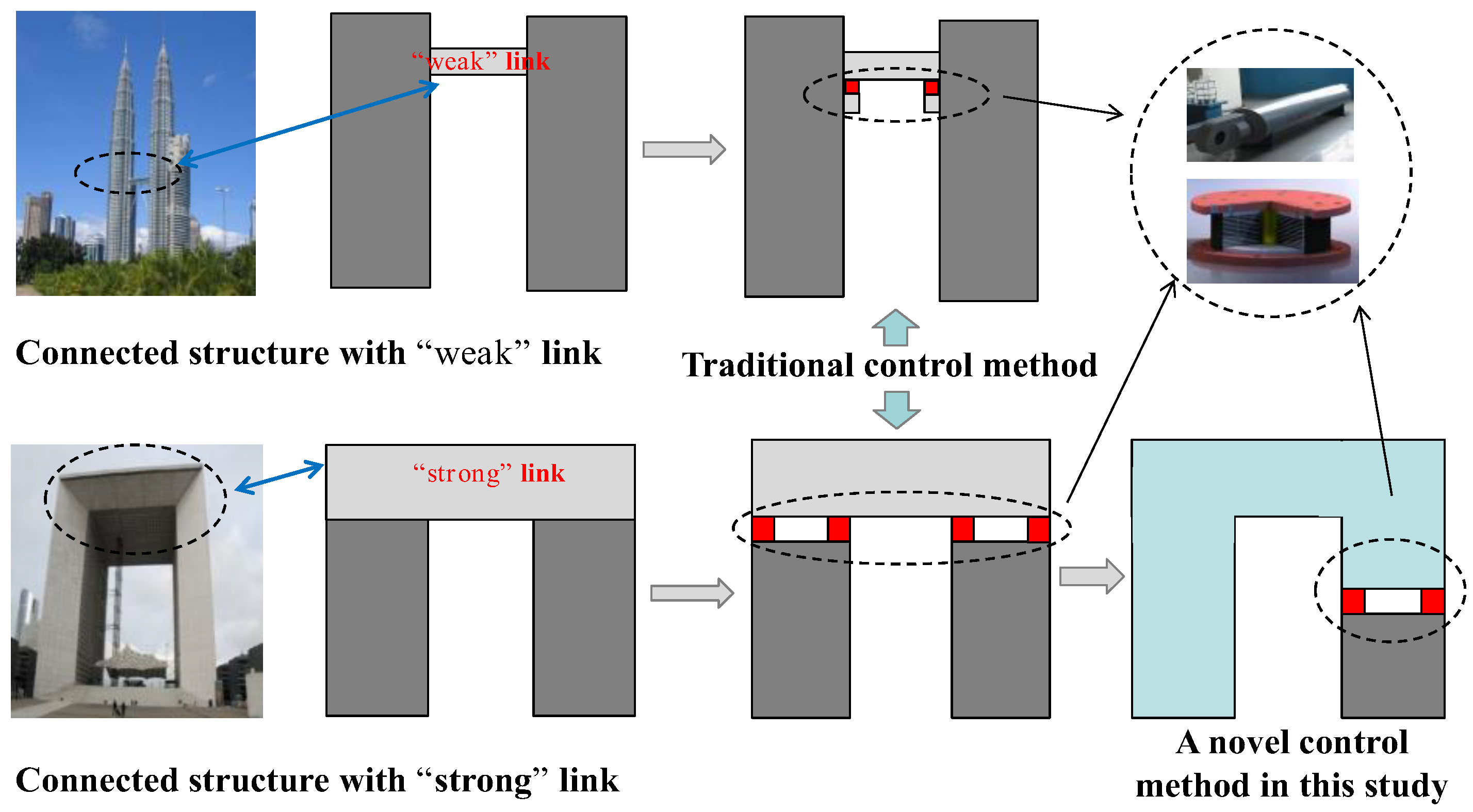
Energy Dissipation and Performance Assessment of the Connected Structure with a One-Side Damping Layer

1
School of Environment and Civil Engineering, Dongguan University of Technology, Dongguan 523808, China
2
School of Civil Engineering, Guangzhou University, Guangzhou 510006, China
3
School of Civil and Transportation Engineering, Ningbo University of Technology, Ningbo 315199, China
*
Author to whom correspondence should be addressed.
Buildings 2022, 12(9), 1438; https://doi.org/10.3390/buildings12091438
Submission received: 10 August 2022 / Revised: 29 August 2022 / Accepted: 6 September 2022 / Published: 13 September 2022
(This article belongs to the Special Issue New Trends in Seismic Performance Evaluation)

Abstract

:
Due to aesthetic demands and the necessity for multi-functionality, a unique structure with one or multiple links connecting adjacent buildings has attracted the attention of researchers. In order to improve vibration control, this study investigates the seismic mitigation performance of a connected structure with a one-side damping layer. The simplified shear model is employed to derive the structure’s motion equation. Based on the Kanai-Tajimi filtered spectrum model, the seismic response variances are calculated using the Lyapunov equation. To investigate the seismic energy distribution and mitigation performance, three models of the connected structure with a damping layer are analyzed using the index of the mean kinetic energy. The results shows that the stiffness and damping coefficient affects the vibration energy, while the excessive stiffness of the damping layer is shown to be detrimental to the damping effects. In sum, the novel connected structure shows excellent damping ability and effectively reduces the vibration energy. Damping layers placed at a lower position with a stiffer structure are shown to enhance the damping effect and lead to more energy dissipation through the damping layer. Thus, this study concludes that the introduction of a One-Side damping layer into the connected structure is an excellent alternative strategy for adjusting the energy distribution of the connected structure and meeting the design requirements.

1. Introduction

High-rise buildings are often considered symbolic of the city. Due to limited land availability, they are often built close together. As it meets aesthetic demands and achieves multi-functionality, a structure with one or more links connecting adjacent buildings has received significant attention. The links of these structures may be a sky bridge, a conventional floor, or a roof. In addition to connecting buildings, these links also provide passages and evacuation routes in cases of emergencies [1]. However, the stiffness and position of the link significantly impact its dynamic characteristics, force mechanism, and aseismic performance [2,3]. These effects were also confirmed using a large number of shake table tests [4,5,6]. Therefore, taking advantage of the connection characteristic of the link is critical to improving the seismic mitigation performance of the building, thus maintaining the seismic response within a reasonable range.
The concept of coupled building control [7] presents alternative measures that can be employed to reduce the dynamic response of the connected structures. Due to the link connecting the adjacent buildings, the investigation and design of connected buildings are much more complicated compared with a single building. Furthermore, the link causes structural coupling for vibrations in the connected buildings [8,9], and hence, affects the modal properties [10,11,12], wind-induced responses [13,14], and seismic responses of the connected structures [3,15,16]. In order to reduce the dynamic response of the adjacent buildings and obtain added damping, it is effective to install dampers between two buildings and use relative lateral movements of the two buildings to dissipate energy. Several studies suggested that viscous dampers, friction dampers, and other dampers effectively reduce the response under different ground motions [17,18,19,20,21]. For example, an improvement in seismic performance was demonstrated by the installation of viscous dampers between the two main towers and the top gallery of a connected building, which were composed of two frame-shear wall towers [18]. Moreover, the optimal design of passive control devices for connected structures was also shown to reduce the seismic response [22]. In particular, lead rubber bearings and linear motion bearings were used as connectors between the sky bridge and the corresponding buildings. The numerical results demonstrated that the design could effectively increase the damping ratio of the coupled buildings, resulting in decreased dynamic responses [1].
The control strategy is critical for damping performance improvement. In general, studies on the seismic response mitigation of connected adjacent buildings that adopt the indirect damping type are relatively scarce. In contrast, cases in which dampers are directly utilized as the connectors linking different buildings have received more attention from researchers. It is worth noting that these dampers can be friction dampers; viscous dampers; and other passive control, semi-active, or active control devices. Fortunately, these dampers were demonstrated to be effective for the adjacent buildings. For example, the dampers were simulated as the Kelvin or Maxwell model, and that demonstrated an excellent control effect on the dynamic response of the parallel structures when using optimal parameters [23,24,25]. A frequency domain method was also developed to evaluate the earthquake input energy for a two-building structure connected using viscous dampers and showed its excellent damping performance [26]. In addition to the dampers mentioned above, friction dampers were shown to be useful in mitigating the seismic response [27], and the shock absorber system was shown to effectively mitigate the impact of the effects between adjacent buildings [28]. Recently, a tuned mass damper and an inerter were proposed as a merged tuned mass-inerter damper and it exhibited superior performance and robustness [29]. Furthermore, to obtain ideal control performance, active control, semi-active control, and hybrid control studies were carried out [30,31,32,33,34,35,36]. The results showed excellent damping effects. However, the major studies mentioned above focused on two adjacent structures with control devices connecting each building. In these cases, the control performance highly depends on the dynamic characteristics of the structures. Thus, the control effect drops sharply if the two adjacent buildings have similar vibration characteristics [23,24,25]. In view of this, improvement in the situation mentioned above is critical.
The link is an essential part of the connected structure. Most often, it is a multi-function bridge in the form of transmission pipelines, walkways, or secondary structures. Thus, the previously discussed dampers connecting each building may not be the “real” link within the connected structure. As shown in Figure 1, to achieve better control performance, the link tends to be designed as a “weak” link with the dampers connecting the link and each building [18,37]. This form of connection provides large relative motion of the links and different buildings, and the excess energy is effectively dissipated. However, most connected structures were originally designed using “strong” link [2,4,38], which presents ample space for business demands, office work, and recreational activities. Compared with the connected structures with ‘‘weak’’ link, there are currently fewer damping strategies for connected structures with ‘‘strong’’ link. The energy dissipation devices, such as dampers, damping walls, or buckling restrained braces, are installed between floors inside the building or the connector is the typical damping scheme. However, the damping effect of such schemes is limited due to the limited relative displacement or relative velocity at both ends of the device [18]. In addition, note that the traditional control concept, as shown in Figure 1, is not applicable to the connected structures with ‘‘strong’’ link, which may lead to the overturning or sliding of the “strong” link due to its large inertial force. Thus, there is a need to construct a more rational damping scheme for connected structures with “strong” link.
This study aims to propose a new control strategy for connected structures with “strong” link. Inspired by the inter-story isolation building [39,40,41,42], this study introduces a damping layer to the connected structures and suggests that it be placed in one of the buildings, namely, as a One-Side damping layer. With this plan, it is convenient to adjust the position and parameters of the damping layer so that adjacent buildings are more different in terms of their vibration characteristics to capture better damping effects. Furthermore, only one of the building set damping layer provides additional security for the whole structure. Given the analysis above, first, this study conducted a linear vibration analysis. Then, the motion equation is derived and it is associated with the random response calculating method of the structure subjected to ground acceleration excitations. To validate the control effect of the proposed control strategy, three typical models are selected for further study via the average kinetic energy. Furthermore, with the use of the energy coefficient, the energy distribution of different parts of the connected structures with a One-Side damping layer is studied. Finally, the corresponding seismic response control performance is evaluated using several earthquake records.

2. Analytical Model of the Connected Structure with a One-Side Damping Layer

This study selects the double-building structure with rigid links as the research focus. The rigid connector is observed to have a significant effect on the dynamic characteristics of the connected structure. According to the structural design requirements, it can be modified to be a “weak” connection to reduce the interaction. In this study, the connected structure with a rigid link is used to study the seismic performance, and the connection is not a “weak” link. This section briefly explains the analytical model of the connected structure.

2.1. Initial Assumptions

The 2D connected structure is illustrated in Figure 2. To investigate connected structures, various simplified models, such as the continuous model [43] and the shear model [21], were proposed. A shear model may provide the basic dynamic characteristic and is convenient for studying seismic performance. Thus, the shear model is employed as the simplified model. The main assumptions about the connected structure are as follows: (1) the lumped mass of the structure is concentrated on each floor, (2) the stiffness of each floor slab is infinite and each floor deformation is considered to be shear deformation, (3) only horizontal vibration is considered, and (4) the simplified model is represented by a two-dimensional series particle mass system.
The connected structure proposed in this study has the same model as the original connected structure. The damping layer is a special floor that is commonly designed to concentrate and dissipate seismic energy to ensure the safety of the main structure. For convenience, the study examines the connected structure with a damping layer placed in the right building. The damping layer consists of one or more combinations of rubber isolation bearings, sliding plate bearings, and other dampers. Studies indicates that when the damper and isolation device (e.g., laminated rubber bearing or friction pendulum bearing) are applied together, the damper can not only dissipate the earthquake energy but also reduce the large relative displacement between the two ends of the isolation device [1,27,37,44,45]. In addition, the combination of negative stiffness element with lead rubber bearing (LRB) can also effectively suppress the deformation of LRB [46]. In this study, the energy dissipation story consists of a linear viscous damper and a laminated rubber bearing. A spring is used to simulate the laminated rubber bearing, and its equivalent stiffness is expressed as kh. The damper is simulated using a linear model, where the damping force is determined only by the multiplication of the difference in velocity between the two ends of the dampers and the damping coefficient ch. Thus, the simplified model is shown in Figure 3.

2.2. Formation of the Analytical Model

The connected structure consists of two buildings and one link, where the left building has nl floors, the right building has nr floors, and the links has nc floors. Based on the assumptions of the shear model, the motion equation for the novel connected structure as shown in Figure 3 can be expressed as Equation (1).
M x ¨ + C x ˙ + K x = M I x ¨ g
In the equation above, x = x L ; x C ; x R is the displacement response vector, where x L = x l 1 , x l 2 , , x l n l T , x C = x c 1 , x c 2 , , x c n c T , and x R = x r 1 , x r 2 , , x r n r T represent the displacement response vectors of the left tower, link, and right tower, respectively. Furthermore, x ¨ g denotes the ground motion acceleration, and n l , n c , and n r represent the number of floors in the left building, link, and right building, respectively. Lastly, I is the unit vector, where the symbols M , K , and C represent the mass, stiffness, and damping matrix, respectively.
The details of M and K are given in Equations (2) and (3).
M = M L M C M R
K = K L C 0 0 0 0 0 k r 0 0 0 0 0 0 0 0 0 k r 0 K R
In the above representation, k r denotes the connected stiffness between the bottom floor of the link and the top of the right tower, which is shown in Figure 2. Next, M L = diag m l 1 m l 2 , , m l n l , M C = diag m c 1 m c 2 , , m c n c , and M R = diag m r 1 m r 2 , , m r n r denote the mass matrixes of the left building, link, and right building, respectively, where K L C represents the stiffness matrix that consists of the left tower and the link. kr and kl can be regarded as the “bottom” stiffness of the link. Lastly, K R denotes the stiffness matrix of the right building and the ith floor is the damping layer. The last two matrixes are expressed as Equations (4) and (5).
K L C = k l 1 + k l 2 k l 2 k l 2 k l n l k l n l k l n l + k l k l k l k l + k c 2 + k r k c 2 k c 2 k c n c k c n c k c n c n l + n c n l + n c
K R = k r 1 + k r 2 k r 2 k r 2 k r i k r i k r i + k h k h k h k h + k r i + 1 k r i + 1 k r i + 1 k r n r k r n r k r n r + k r n r × n r
In the above equations, k l represents the connected stiffness between the bottom floor of the link and the top of the left building, as shown in Figure 2. Based on the Rayleigh damping method [47], the damping coefficient matrix C of the connected structure can be obtained. However, with the introduction of the damping layer, there are differences in the total damping coefficient matrix between the new connected structure with the One-Side damping layer and the original one. To form the damping matrix, several steps are needed to introduce the forming process. First, the original connected structure is separated into two parts, namely, substructure 1 and substructure 2, as shown in Figure 4. Second, Rayleigh damping is used to consider the damping of substructure 1 and substructure 2. Finally, the damping coefficient c h of the damping layer is used to connect substructures 1 and 2.
Substructure 1:
The mass matrix of substructure 1 is expressed as Equation (6).
M 1 = M L C M R u n l + n c + n r i + 1 × n l + n c + n r i + 1
Here, M L C = M L M C n l + n c × n l + n c and M R u = diag ( m r i   m r i + 1     m r n r   ) .
The stiffness matrix of substructure 1 is expressed as Equation (7).
K 1 = K L C 0 0 0 0 0 k r 0 0 0 0 0 0 0 0 0 k r 0 K R u n l + n c + n r i + 1 × n l + n c + n r i + 1
In this equation, K L C and k r are similar to Equation (4) and K R u can be written as Equation (8).
K R u = k r i + 1 k r i + 1 k r i + 1 k r i + 1 + k r i + 2 k r i + 2 k r i + 2 k r n r k r n r k r n r + k r n r i + 1 × n r i + 1
From the above expressions, the mass and stiffness matrix can be obtained. Furthermore, based on the Rayleigh damping method, the damping coefficient matrix can be expressed as Equation (9).
C 1 = α 1 M 1 + β 1 K 1 = C L C 0 0 0 0 0 c r 0 0 0 0 0 0 0 0 0 c r 0 C R u n l + n c + n r i + 1 × n l + n c + n r i + 1
In this equation, α 1 and β 1 are the proportionality factors [47], where c r is the damping coefficient between the bottom floor of the link and the top of the right building, as shown in Figure 2. Furthermore, C L C can be written as similarly type as K L C , where C R u is described as Equation (10).
C R u = c r i + 1 c r i + 1 c r i + 1 c r i + 1 + c r i + 2 c r i + 2 c r i + 2 c r n r c r n r c r n r + c r n r i + 1 × n r i + 1
Substructure 2:
The mass matrix of substructure 2 is expressed as Equation (11).
M 2 = M R d = diag m r 1 m r 2 , , m r i 1
The stiffness matrix of substructure 2 is expressed as Equation (12).
K 2 = K R d = k r 1 + k r 2 k r 2 k r 2 k r 2 + k r 3 k r 3 k r 3 k r i 1 k r i 1 k r i 1 i 1 × i 1
Once the mass and stiffness matrix of substructure 2 is obtained, the damping matrix can be constructed with the Rayleigh damping method and written as Equation (13).
C 2 = C R d = α 2 M 2 + β 2 K 2
C R d = c r 1 + c r 2 c r 2 c r 2 c r 2 + c r 3 c r 3 c r 3 c r i 1 c r i 1 c r i 1 i 1 × i 1
Finally, the damping matrices of substructure 1 and substructure 2 are constructed and the total damping matrix of the connected structure with the damping layer is expressed as Equation (15).
C = C L C 0 0 0 0 0 c r 0 0 0 0 0 0 0 0 0 c r 0 C R d u
Here, C R d u represents the damping matrix of the right building after setting the damping layer, which consists of C R u , C R d , and c h . According to Equations (10) and (14), C R d u can be written in the form of Equation (16).
C R d u = c r 1 + c r 2 c r 2 c r 2 c r i 1 + c h c h c h c h + c r i + 1 c r i + 1 c r i + 1 c r n r c r n r c r n r + c r n r × n r
By substituting Equation (16) for Equation (15), the damping matrix of the connected structure with the damping layer is obtained.

3. Seismic Response Analysis

To determine the seismic response, the following state variables are introduced (Equation (17)).
Y = x x ˙
Combining with Equation (1), Equation (18) is obtained.
Y ˙ = A Y + B x ¨ g
Here, A = 0 I M 1 K M 1 C and B = 0 I .
This study uses the Kanai-Tajimi filtered white noise of ground motion model to investigate the seismic response. It is provided in Equation (19).
S u ¨ g = ω g 4 + 4 ξ g 2 ω g 2 ω 2 ω g 2 ω 2 2 + 4 ξ g 2 ω g 2 ω 2 S 0
In the above equation, S 0 , ω g , and ξ g represent the input power spectrum intensity of the earthquake, natural frequency, and damping ratio of the site soil, respectively. Equation (19) can be expressed as a system of a single degree of freedom. By merging it with Equation (18), the extended state space equation [48] is obtained as Equation (20).
Y ˙ T = A T Y T + B T w 0 t
In this equation, A T = A B C w 0 A w , B T = 0 B w , Y T = Y z w , A w = 0 1 ω g 2 2 ξ g ω g , B w = 0 1 , and C w = ω g 2 2 ξ g ω g .
Let E Y T = E Y T Y T T and E w = B T 2 π S 0 B T T . Then, the Lyapunov equation characterizing Equation (20) can be written as Equation (21).
d E Y T d t = A T E Y T + E Y T A T T + E w
For the stationary response of a structure subjected to stationary random excitation, Equation (21) reduces to the simpler form, and can be provided as Equation (22).
A T E Y T + E Y T A T T + E w = 0
Thus, the mean square response is determined by solving Equation (22).

4. Application

4.1. Mean Kinetic Energy

Energy is a relatively comprehensive index for structural vibration analysis. Thus, when compared with indexes such as displacement, acceleration, and base shear force, energy appears to be a well-suited index for efficient control performance of connected structures with a damping layer. Zhu et al. [23,25] used the average vibration energy to present the optimal formulation of two parallel structures with the Maxwell and Kelvin dampers. The average vibration energy is represented using the random mean kinetic energy and mean elastic energy. The time-averaged total relative energy may be expressed as twice the mean kinetic energy. Thus, the mean kinetic energy of the entire structure is used to examine the control performance of the novel connected structure.

4.2. Numerical Example

This study examines three models, which cover the structural symmetry and asymmetry of the connected structure. Model 1 is a symmetrical structure that has 16 floors in each tower. The mass and shear stiffness of the left and right buildings are uniform for all stories with a mass of 2.5 × 10⁶ kg and shear stiffness of 5.5 × 10⁹ N/m. The link body has three floors, with the mass and stiffness of each floor being 4 × 10⁶ kg and 7.0 × 10⁹ N/m, respectively. The shear stiffness of the bottom of the link that connects the top of the left and right buildings are kl = kr = 5.5 × 10⁹ N/m. Second, model 2 is an asymmetrical structure that has 16 floors in each building, with the right building considered to be “softer”. The mass and shear stiffness of each floor in the left buildings are 2.5 × 10⁶ kg and 5.5 × 10⁹ N/m, respectively. On the other hand, for the right tower, these are 1.6 × 10⁶ kg and 2.0 × 10⁹ N/m, respectively. The link body has three floors, while the mass and stiffness of each floor are 4 × 10⁶ kg and 7.0 × 10⁹ N/m, respectively. The shear stiffness of the bottom of the link connecting the top of the left and right buildings are kl = 5.5 × 10⁹ N/m and kr = 2.0 × 10⁹ N/m, respectively. Lastly, model 3 is another asymmetrical structure with 16 floors in each building. For this model, the right building is defined as “stiffer”. The mass and shear stiffness of each floor in the left tower are 2.5 × 10⁶ kg and 5.5 × 10⁹ N/m, respectively. For the right tower, these factors are 3.3 × 10⁶ kg and 10.0 × 10⁹ N/m, respectively. The link body has three floors, while the mass and shear stiffness of each floor are 4 × 10⁶ kg and 7.0 × 10⁹ N/m, respectively. The shear stiffness of the bottom of the link that connects the top of the left and right buildings are kl = 5.5 × 10⁹ N/m and kr = 10.0 × 10⁹ N/m, respectively.
The Kanai-Tajimi filtered white-noise spectrum model is adopted as the ground acceleration spectrum in the computation. This is done in order to provide the random earthquake response for the control structure with optimal parameters and an adequate position of the damping layer. To reflect the firm soil conditions, the earthquake intensity is selected as S0 = 4.65 × 10⁻⁴ m2/rad·s3, while the characteristic parameters in the spectral density functions are taken as wg = 15 rad/s and ξg = 0.6 [25].

4.3. Effects of the Damping Layer Parameters

The results in this section demonstrate the control effects and their corresponding influencing factors, such as the position, damping coefficient, and stiffness of the damping layer. All these parameters significantly influence the structural energy. Thus, Figure 5, Figure 6 and Figure 7 represent 3D images that depict the variation pattern of the mean kinetic energy of the novel connected structure with the damping coefficient and stiffness when the damping layers are placed at the 3rd, 9th, or 15th floors of the right building.
Figure 5 illustrates the mean kinetic energy of model 1 over the damping coefficient and stiffness of the damping layer. The damping coefficient and stiffness are observed to significantly influence the energy, while the excessive stiffness of the damping layer is detrimental to the damping effects. For instance, when the damping layer is located at the third floor, as in Figure 5a, the mean kinetic energy increases as the stiffness increases. However, the trend of the damping coefficient differs from the stiffness trend. For one, there is an optimal value for the damping coefficient at which the mean kinetic energy remains in the valley areas. As most of its energy is concentrated and dissipated on the damping layer, the proposed structure exhibits an excellent control performance with the optimal damping coefficient. In addition, as illustrated in Figure 5b,c, similar results to Figure 5a are obtained. The lower the position of the damping layer, the lower the kinetic energy of the novel connected structure. Furthermore, a lower position of the damping layer tends to result in broader low-energy areas, suggesting that placing the damping layer at the lower floor causes better robustness and damping performance. In other words, lower stiffness, an optimal damping coefficient, and lower location results in better control performance.
Figure 6 and Figure 7 show the dependence between the mean kinetic energy and the parameters and position of the damping layer for models 2 and 3. Although similar trends are observed between the three models, there are slight variations as well. For one, when the optimal damping parameter is obtained for model 2, the area of the optimal parameter is narrower than for model 1, meaning that the area for model 1 is flatter. This phenomenon is most evident when the damping layer is placed at a higher floor, e.g., the 15th floor. For model 3, the curved surface depicting the mean kinetic energy over the parameters is flatter. The mean kinetic energy remains at a lower value than in model 1 (e.g., when the damping layer is located at the third floor, the corresponding minimum energies of model 3 and model 1 are 5.018 × 10⁴ J and 5.496 × 10⁴ J, respectively). The above mentioned results mean better control performance and robustness with the damping layer located in the stiffer building for model 3. In general, when the damping layer is situated in the stiffer tower and on a lower floor, it improves the damping effect and leads to a greater energy concentration and dissipation on the damping layer. Thus, the preferred damping effect can be achieved.

4.4. Optimal Parameters and Energy Reduction Coefficients

Figure 8 illustrates the relationship between the optimal damping coefficient and the position of the damping layer. The optimal stiffness of these models is not displayed since their values tended to be zero. As Figure 8 shows, the optimal damping coefficient exhibits a downward trend with the increase of the damping layer position, i.e., the lower the floor, the greater the optimal damping coefficient required. For example, for the damping layers locates at the 3rd, 9th, or 15th floors, the optimal damping coefficients for model 1 are 1.12 × 10⁸ N·s/m, 0.71 × 10⁸ N·s/m, and 0.34 × 10⁸ N·s/m, respectively. The optimal damping coefficients of model 2 are 0.42 × 10⁸ N·s/m, 0.29 × 10⁸ N·s/m, and 0.07 × 10⁸ N·s/m, respectively. Lastly, the optimal damping coefficients of model 3 are 1.88 × 10⁸ N·s/m, 1.17 × 10⁸ N·s/m, and 0.61 × 10⁸ N·s/m, respectively. In addition, the damping coefficient of model 2, in which the damping layer is located in the softer building, is smaller. However, the damping coefficient of model 3 with the damping layer in the stiffer building is larger and that of model 1 is intermediate. The above phenomenon indicates that the damping layer in the stiffer tower required a greater damping coefficient to dissipate more energy and maintain its optimal control state.
This study defines the energy reduction coefficient as the average kinetic ratio between the connected structure with and without a damping layer. This notion is used to investigate the damping effects of the new connected structure. The energy reduction coefficient analysis is based on the optimal parameters of the damping layer. As shown in Figure 9, the control performance of all structures tends to decline as the position of the damping layer rises. The exception to this is the seventh floor. For a better damping effect, the damping layer should be situated in a lower floor. Furthermore, there is a lesser difference in these structures’ damping performances when the damping layer is placed at a lower floor. For instance, when the damping layer is located at the third floor, the energy reduction coefficients are 0.1273, 0.1637, and 0.1132 for model 1, model 2, and model 3, respectively. In comparison, when the damping layer is located at the 15th floor, their counterparts are 0.2469, 0.5770, and 0.1809, respectively. In general, the energy reduction coefficient of model 3 is the smallest, while that of model 1 is intermediate. Lastly, the coefficient of model 2 is the highest. Unsurprisingly, model 3 exhibits the best damping effect. Combined with Figure 8, it is found that a larger optimal damping coefficient is required to achieve this damping effect.
The damping layer is introduced to the original connected structure and the interaction between its substructures is similar to the control system of adjacent structures. Thus, the frequency difference between the two substructures significantly impacts its damping effect [23]. As shown in Figure 10, this study uses the first-order frequency ratio between substructure 1 and substructure 2 in each model to investigate the relationship between the damping layer position and the damping effect. As observed from both Figure 10 and Table 1, the relationship between the first-order frequency ratio and the floor number is opposite to the variation trend of the average kinetic energy coefficient. When the damping layer is located at a lower position, there is a larger difference in dynamic characteristics between substructure 1 and substructure 2 in each of the three models. The energy dissipation device of the damping layer retains high energy dissipation efficiency. However, this difference becomes smaller when the damping layer is situated at a higher position. Thus, the energy dissipation efficiency of the damping layer is reduced, and the damping effect also degenerates. The damping layer located in the stiffer building (model 3) results in a greater difference in the dynamic characteristics of the two substructures and further improves the overall damping effect of the novel connected structure. Thus, the difference in the dynamic characteristics is one of the key factors contributing to the control performance.

4.5. Seismic Energy Distribution

The energy distribution relationship presents the energy flow law among different substructures. Due to the optimal parameters of the damping layer located at different floors, it is crucial to understand the energy concentration state via the energy distribution proportion of each part. Figure 11 provides the energy distribution proportion between substructure 1 and substructure 2. When the damping layer is located at the bottom of the right building, the mean kinetic energy of substructure 1 is larger than that in substructure 2. This indicates that more floors are contained in substructure 1 than in substructure 2. With the increase of the position of the damping layer, the energy proportion of the two substructures gradually approaches each other. The energy proportion difference for the two substructures in model 3 is smaller, while it is larger for model 2.
Figure 12 illustrates the energy distribution ratio. Taking the ratio of the mean kinetic energy of the left building (abbreviated as L), the link body (abbreviated as C), and the right building (abbreviated as R) over the total mean kinetic energy as the index of the energy distribution proportion, the energy proportion of C slowly rises with the increase of the position of the damping layer. Comparing all three models, the energy proportion for C in model 2 is the highest. It is followed by model 1, while the proportion of model 3 is the smallest, indicating that the mean kinetic energy stored in the linked part decreases once the damping layer is incorporated into the stiffer building. For the left building, the proportion of the mean kinetic energy increases with the increase of the position of the damping layer. The proportional distribution of each model is similar to that of C. However, the increases of the energy proportions of L are larger than C with the increase of the damping layer. For the right building R, the mean kinetic energy decreases with the increase of the position of the damping layer. From the above analysis, the damping layer appears to improve the energy distribution of the connected structure effectively. When the damping layer is located at a higher floor, the energy of the structure gradually transfers to the left building and the link body. Thus, the damping layer is a valuable means for adjusting the energy distribution so that it is in line with the design requirements.
Energy is an index that was used to comprehensively evaluate the seismic mitigation performance of the connected structure. As shown in Figure 13, the energy reduction coefficients of L, C, and R for the connected structure are defined as the mean kinetic energy ratio for the connected structure with and without the damping layer. From the perspective of the energy reduction coefficient, each part of the three models shows excellent energy reduction when the damping layers are present. In addition, the lower position of the damping layer enhances the control effect. In this regard, model 3 performs best, while model 1 is second and model 2 is the last. The results from the energy study also show that L and C display a better damping performance within the same model, whereas R exhibits a slightly worse performance than them. For example, for the damping layer located at the third floor, the energy reduction coefficients of L, C, and R for model 1 are 0.1071, 0.1064, and 0.1618, respectively. Less or no stiffness of the damping layer design may lead to greater energy concentration in the right building, as a large amount of energy will be dissipated in the damping layer. Thus, a connected structure with a damping layer effectively regulates the excessive energy dissipation.

4.6. Seismic Mitigation Performance

In this section, two typical seismic records are used to examine the damping performance of the connected structure. The two records are for the NS component of the El Centro earthquake in 1940 and the Taft earthquake in 1952, both of which are adjusted to a peak ground acceleration of 0.2 g.
The seismic response study of the proposed connected structure is carried out at the optimal values of ch and kh equal to zero in all cases. The optimal values of ch for the three models are listed in Section 4.3. Using the ground motion excitation, the maximal story drifts and the maximal absolute acceleration at each floor for the structures with and without a damping layer are computed to demonstrate the control effectiveness of the novel connected structure. Figure 14 and Figure 15 compare the maximal story drifts and the maximal absolute acceleration for the left and right towers, in which N represents the connected structure without a damping layer and R* represents the connected structure with a One-Side damping layer in the right building. The * (asterisk) indicates the position of the damping layer.
As Figure 14 and Figure 15 show, the maximal story drifts and absolute acceleration of both the left and right buildings are significantly reduced. For model 1 and without the damping layer, the bottom drift is 0.0108 m in the left building and 0.0108 m in the right building. Model 1 has a symmetrical structure. With the damping layer located at the 3rd, 9th, or 15th floors, the bottom drifts are reduced to 0.0062 m, 0.0066 m, and 0.0083 m in the left building and 0.0049 m, 0.0072 m, and 0.0080 m in the right building, respectively. This leads to 42.59%, 38.89%, 23.15%, 54.63%, 33.33%, and 25.93% reduction, respectively. However, some special floors cause unexpected results. For example, the top drift of the left building is slightly amplified in model 1 when the damping layer is located at the 15th floor. Furthermore, the reduction of the absolute acceleration is similar to that of the story drifts. In particular, it is similar to the traditional isolation system in which the maximum story drifts of the damping layer may be up to ten times that of the normal story due to its small stiffness. Nevertheless, it is essential for the larger story drift of the damping layer to satisfy excessive energy dissipation. Thus, retaining enough stiffness of the damping layer or implementing a limit is necessary to reduce a larger drift without excessively losing its damping performance. Moreover, the proposed connected structure is observed to outperform the traditional isolation system regarding the security of the damping layer. This may be due to the fact that the superstructure of the former can be constrained by the left building whereas that of the latter lacks this strong constraint from other parts.
Due to spatial constraints, only the top-level displacement time history curve of model 1 is further analyzed in this study. The corresponding damping effects is represented as the response reduction ratio of the connected structure with and without the damping layer. With the optimal parameters of the damping layer, the proposed connected structure is highly effective in mitigating the response of both the top floor displacement and acceleration (as shown in Figure 16). Similarly, as shown in Figure 17, the base shear of the left and right buildings can be effectively controlled, especially when the damping layer is located at the third floor with reduction ratios of 0.5756 and 0.4599, respectively. To investigate the response of the proposed structure, Table 2, Table 3, Table 4 and Table 5 illustrate the top floor displacement, absolute acceleration, and base shear of the left and right buildings of the three models under the El Centro/Taft ground excitations. Each model performs excellently at suppressing the seismic response. As the position of the damping layer rises, the control effect worsens. However, its change trend for the absolute acceleration is not significant. In general, the damping layer placed in a lower floor exhibits a better performance on seismic response peaks suppression, such as displacement, acceleration, and base shear. Moreover, the stiffer building containing a damping layer contributes more in improvement of the damping effect for the whole structure.

5. Conclusions

In order to obtain excellent control performance of a strongly connected structure, this study proposed a connected structure with a One-Side damping layer. The study selected a double-building structure with rigid links as the research focus. Based on the assumption of the shear model, the motion equation of the novel connected structure with a damping layer was derived. The variances of the response of the structure for the extended state space equation were calculated using the Kanai-Tajimi filtered white noise of the ground motion model. The variances were the solution of the Lyapunov equation. Finally, the mean kinetic energy of the structure was used to examine the seismic mitigation performance. Three models, including symmetrical and asymmetrical structural types of connected structures, were examined in this study.
The main conclusions of this study are presented as follows:
(1) The damping layer located at the stiffer tower and lower floors contributes more in the damping effect for the proposed structure. It can be attributed to more energy concentration and dissipation through the damping layer.
(2) With the increase in the damping layer position, the optimal damping coefficient shows a decreasing trend. At a lower position, the damping layer creates a larger difference in dynamic characteristics between substructure 1 and substructure 2 of each model and leads to a higher energy dissipation efficiency.
(3) The damping layer can effectively improve the energy distribution of the connected structure. When the damping layer is situated in higher floors, the energy of the structure gradually transfers to the left building and the link body. In contrast, the energy proportion of the right building gradually decreases. The damping layer represents a valuable means for adjusting the energy distribution and keeping it in line with the design requirements.
(4) With the optimal parameters, the maximum story drifts and absolute acceleration in all stories of both the left and right buildings are significantly reduced. It is an effective control measure to introduce the damping layer, especially for seismic response peak suppression.
This study mainly focuses on the damping performance of the proposed structure under horizontal seismic excitation in the elastic range. Further studies on torsional effects due to stiffness asymmetry, elastoplastic analysis, and multidimensional vibration analysis are needed.

Author Contributions

Conceptualization, L.L. and Y.Z.; methodology, L.L. and Y.Z.; software, Z.P.; validation, Z.P.; formal analysis, L.L.; investigation, L.L. and Y.Z.; resources, Q.L.; data curation, Q.L.; writing—original draft preparation, L.L.; writing—review and editing, Y.Z; visualization, Z.P.; supervision, Q.L.; project administration, Y.Z.; funding acquisition, L.L. All authors have read and agreed to the published version of the manuscript.

Funding

This research was funded by the National Natural Science Foundation of China (grant numbers 51908129 and 52008216), National Key R&D Program of China (grant number 2019YFC1511004), and Guang Dong Basic and Applied Basic Research Foundation (grant number 2020A1515110806).

Data Availability Statement

The data presented in this study are available on request from the authors.

Conflicts of Interest

The authors declare no conflict of interest.

References

  1. Lee, D.G.; Kim, H.S.; Ko, H. Evaluation of coupling control effect of a sky-bridge for adjacent tall buildings. Struct. Design Tall Spec. Build. 2010, 21, 311–328. [Google Scholar] [CrossRef]
  2. Zhou, Y.; Lu, X.L.; Qian, J. Dynamic test on a multi-tower connected building structure. In Proceedings of the 3rd International Conference on Advances in Experimental Structural Engineering, San Francisco, CA, USA, 3 February 2009. [Google Scholar]
  3. Zhou, Y.; Lu, X.L.; Lu, W.S.; Qian, J. Study on the seismic performance of a multi-tower connected structure. Struct. Design Tall Spec. Build. 2011, 20, 387–401. [Google Scholar] [CrossRef]
  4. Zhou, D.Y.; Guo, C.T.; Wu, X.H.; Zhang, B. Seismic evaluation of a multi-tower connected building by using three software programs with experimental verification. Shock Vib. 2016, 2016 Pt 8, 8215696. [Google Scholar]
  5. Zhou, Y.; Lu, X.L.; Lu, W.S.; He, Z.J. Shake table testing of a multi-tower connected hybrid structure. Earth. Eng. Vib. 2009, 8, 47–59. [Google Scholar] [CrossRef]
  6. Lu, X.L.; Chen, L.Z.; Zhou, Y.; Huang, Z.H. Shaking table model tests on a complex high-rise building with two towers of different height connected by trusses. Struct. Design Tall Spec. Build. 2009, 18, 765–788. [Google Scholar] [CrossRef]
  7. Klein, R.E.; Cusano, C.; Stukel, J. Investigation of a method to stabilize wind induced oscillations in large structures. In Proceedings of the ASME Winter Annual Meeting, New York, NY, USA, 18–21 June 1972. [Google Scholar]
  8. Lim, J.; Bienkiewicz, B. Effects of structural and aerodynamic couplings on the dynamic response of tall twin buildings with a skybridge. In Proceedings of the Structures Congress 2009: Structures Congress 2009: Don’t Mess with Structural Engineers: Expanding Our Role, Austin, TX, USA, 30 April–2 May 2009. [Google Scholar]
  9. Westermo, B.D. The dynamics of interstructural connection to prevent pounding. Earthq. Eng. Struct. Dyn. 1989, 18, 687–699. [Google Scholar] [CrossRef]
  10. Song, J.; Tse, K.T. Dynamic characteristics of wind-excited linked twin buildings based on a 3-dimensional analytical model. Eng. Struct. 2014, 79, 169–181. [Google Scholar] [CrossRef]
  11. Tse, K.T.; Song, J. Modal analysis of a linked cantilever flexible building system. J. Struct. Eng. 2015, 141, 04015008. [Google Scholar] [CrossRef]
  12. Lim, J.; Bienkiewicz, B.; Richards, E. Modeling of structural coupling for assessment of modal properties of twin tall buildings with a skybridge. J. Wind Eng. Ind. Aerodyn. 2011, 99, 615–623. [Google Scholar] [CrossRef]
  13. Hu, G.; Tse, K.T.; Song, J.; Liang, S. Performance of wind-excited linked building systems considering the link-induced structural coupling. Eng. Struct. 2017, 138, 91–104. [Google Scholar] [CrossRef]
  14. Song, J.; Tse, K.T.; Tamura, Y.; Kareem, A. Aerodynamics of closely spaced buildings: With application to linked buildings. J. Wind Eng. Ind. Aerodyn. 2016, 149, 1–16. [Google Scholar] [CrossRef] [Green Version]
  15. Hejazi, F.; Dalili, M.S.; Noorzaei, J.; Jaafar, M.S.; Abdullah, A.A.A.; Thanoon, W.A. Seismic response evaluation of RC tower connected to short rigid buildings. Key Eng. Mater. 2011, 462, 569–575. [Google Scholar] [CrossRef]
  16. Longjam, S.; Shirai, K. Numerical investigation of earthquake response reduction effects by negative stiffness connection for adjacent building structures. Structures 2022, 38, 672–688. [Google Scholar] [CrossRef]
  17. Farhad, B.; Sattar, D.; Ali, T.; Behrokh, H.H. A method for rapid estimation of dynamic coupling and spectral responses of connected adjacent structures. Struct. Des. Tall. Spec. Build. 2016, 25, 605–625. [Google Scholar]
  18. Chen, X.W.; Han, X.L. Research summary on long-span connected tall building structure with viscous dampers. Struct. Des. Tall Spec. Build. 2010, 19, 439–456. [Google Scholar] [CrossRef]
  19. Zhang, S.; Hu, Y.; Zhang, C.; Li, S.; Tan, P. Performance-Based Compositive Passive Control Analysis of Multi-Tower Building with Chassis: Optimization of Kelvin-Voigt Dampers. Buildings 2022, 12, 137. [Google Scholar] [CrossRef]
  20. Taleshian, H.A.; Roshan, A.M.; Amiri, J.V. Seismic pounding mitigation of asymmetric-plan buildings by using viscoelastic links. Structures 2022, 36, 189–214. [Google Scholar] [CrossRef]
  21. Ge, D.D.; Zhu, H.P.; Wang, D.S.; Huang, M.S. Seismic response analysis of damper-connected adjacent structures with stochastic parameters. J. Zhejiang Univ. SCIENCE A 2010, 11, 402–414. [Google Scholar] [CrossRef]
  22. Wu, Q.Y.; Dai, J.Z.; Zhu, H.P. Optimum design of passive control devices for reducing the seismic response of twin-tower-connected structures. J. Earth. Eng. 2018, 22, 826–860. [Google Scholar] [CrossRef]
  23. Zhu, H.; Wen, Y.; Iemura, H. A study on interaction control for seismic response of parallel structures. Comput. Struct. 2001, 79, 231–242. [Google Scholar] [CrossRef]
  24. Zhu, H.P.; Xu, Y.L. Optimum parameters of Maxwell model-defined dampers used to link adjacent structures. J. Sound Vib. 2005, 279, 253–274. [Google Scholar] [CrossRef]
  25. Zhu, H.P.; Ge, D.D.; Huang, X. Optimum connecting dampers to reduce the seismic responses of parallel structures. J. Sound Vib. 2011, 330, 1931–1949. [Google Scholar] [CrossRef]
  26. Takewaki, I. Earthquake input energy to two buildings connected by viscous dampers. J. Struct. Eng. 2007, 133, 620–628. [Google Scholar] [CrossRef]
  27. Bhaskararao, A.V.; Jangid, R.S. Seismic analysis of structures connected with friction dampers. Eng. Struct. 2006, 28, 690–703. [Google Scholar] [CrossRef]
  28. Raheem, S.E.A. Mitigation measures for earthquake induced pounding effects on seismic performance of adjacent buildings. Bull. Earth. Eng. 2014, 12, 1705–1724. [Google Scholar] [CrossRef]
  29. Palacios-Quiñonero, F.; Rubió-Massegú, J.; Rossell, J.M.; Karimi, H.R. Design of inerter-based multi-actuator systems for vibration control of adjacent structures. J. Frankl. Inst. 2019, 356, 7785–7809. [Google Scholar] [CrossRef]
  30. Hori, N.; Christenson, R.E.; Seto, K.; Spencer, B.F., Jr. Active vibration control of coupled buildings using relative movement. In Proceedings of the Fifth Motion and Vibration Conference, Sydney, Australia, 4–8 December 2000. [Google Scholar]
  31. Christenson, R.E.; Spencer, B.F., Jr.; Hori, N.; Seto, K. Coupled building control using acceleration feedback. Comput.-Aided Civ. Infrastruct. Eng. 2003, 18, 4–18. [Google Scholar] [CrossRef]
  32. Kim, H.; Adeli, H. Hybrid control of smart structures using a novel wavelet-based algorithm. Comput.-Aided Civ. Infrastruct. Eng. 2005, 20, 7–22. [Google Scholar] [CrossRef]
  33. Al-Ghazali, A.S.; Shariatmadar, H. Hybrid active control of adjacent buildings interconnected by viscous dampers utilizing type–2 fuzzy controller considering soil-structure interaction. Structures 2021, 33, 292–306. [Google Scholar] [CrossRef]
  34. Doroudi, R.; Lavassani, S.H.H. Connection of coupled buildings: A state-of-the-art review. Structures 2021, 33, 1299–1326. [Google Scholar] [CrossRef]
  35. Cundumi, O.; Suárez, L.E. Numerical investigation of a variable damping semiactive device for the mitigation of the seismic response of adjacent structures. Comput.-Aided Civ. Infrastruct. Eng. 2008, 23, 291–308. [Google Scholar] [CrossRef]
  36. Fathi, F.; Bahar, O. Hybrid coupled building control for similar adjacent buildings. KSCE J. Civ. Eng. 2017, 21, 265–273. [Google Scholar] [CrossRef]
  37. Hou, J.J.; Rong, B.S.; Han, X.L. Theoretical and experimental study of twin-tower tall building connected with damper-supported corridor under seismic excitation. In Proceedings of the 14th World Conference on Earthquake Engineering, Beijing, China, 12–17 October 2008. [Google Scholar]
  38. Mu, Z.G.; Wang, L.; Fan, Z. Analysis of stress response for the super high rise double-tower connected structure with the trusses of changing rigidity. Adv. Mater. Res. 2011, 291, 1559–1563. [Google Scholar] [CrossRef]
  39. Chang, K.C.; Hwang, J.S.; Wang, S.J.; Lee, B.H. Analytical and experimental studies on seismic behavior of buildings with mid-story isolation. In Proceedings of the ATC and SEI Conference on Improving the Seismic Performance of Existing Buildings and Other Structures, San Francisco, CA, USA, 9–11 December 2009. [Google Scholar]
  40. Zhou, F.L.; Zhang, Y.; Tan, P. Theoretical study on story isolation system. China Civ. Eng. J. 2009, 42, 1–8. (In Chinese) [Google Scholar]
  41. Tasaka, M.; Mori, N.; Yamamoto, H.; Murakami, K.; Sueoka, T. Applying seismic isolation to buildings in Japan-Retrofitting and middle-story isolation. In Proceedings of the 18th Analysis and Computation Specialty Conferences, Vancouver, BC, Canada, 24–26 April 2008. [Google Scholar]
  42. Zhou, Q.; Singh, M.P.; Huang, X.Y. Model reduction and optimal parameters of mid-story isolation systems. Eng Struct. 2016, 124, 36–48. [Google Scholar] [CrossRef]
  43. Bao, S.H.; Wang, J.D. Vibration calculation and dynamic characteristics of multi-tower connected structure with enlarged base. Build. Struct. 1997, 6, 40–44. (In Chinese) [Google Scholar]
  44. Khedmatgozar Dolati, S.S.; Mehrabi, A.; Khedmatgozar Dolati, S.S. Application of viscous damper and laminated rubber bearing pads for bridges in seismic regions. Metals 2021, 11, 1666. [Google Scholar] [CrossRef]
  45. Chen, X.; Xiong, J. Seismic resilient design with base isolation device using friction pendulum bearing and viscous damper. Soil Dyn. Earth. Eng. 2022, 153, 107073. [Google Scholar] [CrossRef]
  46. Chen, X.; Ikago, K.; Guan, Z.; Li, J.; Wang, X. Lead-rubber-bearing with negative stiffness springs (LRB-NS) for base-isolation seismic design of resilient bridges: A theoretical feasibility study. Eng. Struct. 2022, 266, 114601. [Google Scholar] [CrossRef]
  47. Clough, R.; Penzien, J. Dynamics of Structures; McGraw-Hill Inc.: New York, NY, USA, 1993. [Google Scholar]
  48. Fang, C.J.; Spencer, B.F., Jr.; Xu, J.Q.; Tan, P.; Zhou, F.L. Optimization of damped outrigger systems subject to stochastic excitation. Eng Struct. 2019, 191, 280–291. [Google Scholar] [CrossRef]
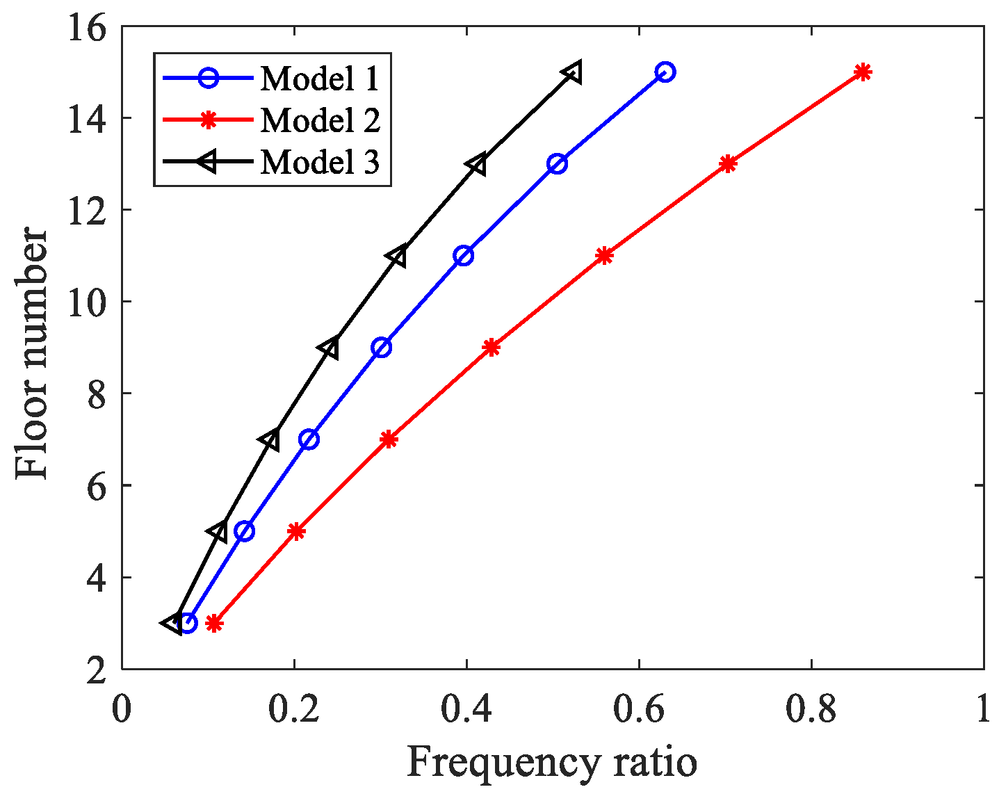
Figure 1. Illustration of the connected structure and their control methods.
Buildings 12 01438 g001
Figure 2. The simplified model of the connected structure.
Buildings 12 01438 g002
Figure 3. The simplified model of the proposed structure.
Buildings 12 01438 g003
Figure 4. The allocation of the substructure.
Buildings 12 01438 g004
Figure 5. The mean kinetic energy versus the parameters and position of the damping layer (model 1): (a) the damping layer is located at the 3rd floor; (b) the damping layer is located at the 9th floor; (c) the damping layer is located at the 15th floor.
Buildings 12 01438 g005
Figure 6. The mean kinetic energy versus the parameters and position of the damping layer (model 2): (a) the damping layer is located at the 3rd floor; (b) the damping layer is located at the 9th floor; (c) the damping layer is located at the 15th floor.
Buildings 12 01438 g006
Figure 7. The mean kinetic energy versus the parameters and position of the damping layer (model 3): (a) the damping layer is located at the 3rd floor; (b) the damping layer is located at the 9th floor; (c) the damping layer is located at the 15th floor.
Buildings 12 01438 g007
Figure 8. Optimal parameters versus position of the damping layer.
Buildings 12 01438 g008
Figure 9. The energy reduction coefficient versus the position of the damping layer.
Buildings 12 01438 g009
Figure 10. The energy reduction coefficient versus the position of the damping layer.
Buildings 12 01438 g010
Figure 11. The energy proportion of the two substructures.
Buildings 12 01438 g011
Figure 12. Energy distribution ratio.
Buildings 12 01438 g012
Figure 13. Energy reduction coefficient.
Buildings 12 01438 g013
Figure 14. Story drift (El Centro): (a) left building of model 1; (b) left building of model 2; (c) left building of model 3; (d) right building of model 1; (e) right building of model 2; (f) right building of model 3.
Buildings 12 01438 g014
Figure 15. Absolute acceleration (El Centro): (a) left building of model 1; (b) left building of model 2; (c) left building of model 3; (d) right building of model 1; (e) right building of model 2; (f) right building of model 3.
Buildings 12 01438 g015
Figure 16. Top response of model 1 (El Centro): (a) displacement; (b) absolute acceleration.
Buildings 12 01438 g016
Figure 17. Base shear response of model 1 (El Centro): (a) base shear of the left building; (b) base shear of the right building.
Buildings 12 01438 g017
Table 1. The 1st frequencies of substructures 1 and 2 and the ratios between them.
Damping LayerModel 1Model 2Model 3
Sub-
Structure 1 (rad/s)
Sub-
Structure 2 (rad/s)
1st Frequency RatioSub-
Structure 1 (rad/s)
Sub-
Structure 2 (rad/s)
1st Frequency RatioSub-
Structure 1 (rad/s)
Sub-
Structure 2 (rad/s)
1st Frequency Ratio
32.1928.990.0762.3321.850.1072.0534.020.060
52.3116.290.1422.4812.280.2022.1719.120.113
72.4511.310.2172.648.520.3092.3013.270.173
92.618.660.3002.806.520.4282.4610.160.242
112.787.010.3962.965.280.5602.628.230.321
132.975.890.5053.124.440.7032.866.910.413
153.205.080.6303.293.830.8593.135.960.525
Table 2. Damping effects for the top floor response (El Centro).
Damping LayerModel 1Model 2Model 3
DisplacementAccelerationDisplacementAccelerationDisplacementAcceleration
30.65170.73890.72340.98410.66800.6624
90.78980.76140.85160.97030.77400.7182
150.80180.62600.92440.90540.96480.6507
Table 3. Damping effects for the top floor response (Taft).
Damping LayerModel 1Model 2Model 3
DisplacementAccelerationDisplacementAccelerationDisplacementAcceleration
30.60330.70590.72840.69420.51610.4218
90.67510.75400.79510.78030.59340.4492
150.9050.72880.95170.83170.84310.4648
Table 4. Damping effects for the base shear (El Centro).
Damping LayerModel 1Model 2Model 3
LRLRLR
30.57560.45990.67320.51620.58070.4810
90.61560.66910.85490.63640.72150.7248
150.77480.74720.88730.89470.79430.8149
Table 5. Damping effects for the base shear (Taft).
Damping LayerModel 1Model 2Model 3
LRLRLR
30.49750.45540.64660.55490.40530.3906
90.55600.61820.72550.82330.42630.4872
150.69930.90600.97061.12960.58330.6877
Publisher’s Note: MDPI stays neutral with regard to jurisdictional claims in published maps and institutional affiliations.

