Article

Experimental Investigation of Seismic Performance of a Hybrid Beam–Column Connection in a Precast Concrete Frame

1
College of Civil Engineering, Fuzhou University, Fuzhou 350116, China
2
Key Laboratory of Building Collapse Mechanism and Disaster Prevention, China Earthquake Administration, Sanhe 065201, China
3
College of Artificial Intelligence, Yango University, Fuzhou 350015, China
*
Author to whom correspondence should be addressed.
Buildings 2022, 12(6), 801; https://doi.org/10.3390/buildings12060801
Submission received: 13 May 2022 / Revised: 7 June 2022 / Accepted: 8 June 2022 / Published: 10 June 2022
(This article belongs to the Topic Advances in Construction and Project Management)

Abstract

:
Prefabricated beam–column connections are the most vulnerable components of prefabricated buildings during earthquake events. The seismic performance of the beam–column connection is functional as the critical component plays a key role in structural safety. This study aimed to develop a novel hybrid prefabricated concrete (HPC) connection, combining with wet and dry connection techniques, to enhance the seismic performance of prefabricated concrete frames. A quasi-static experimental investigation was carried out to examine the seismic performance of the proposed connection. Two full-scale prefabricated connection specimens utilizing the proposed HPC connection and another code-defined monolithic prefabricated concrete (PC) connection were tested under cyclic loading, keeping the axial load on the column constant. The ductility, stiffness degradation, energy dissipation capacity, post-tensioned force, and residual displacement were obtained based on the experimental output. The results indicated that the HPC connection developed had high construction efficiency and better seismic performance than the conventional PC connection. The strength and energy dissipation capacity were significantly improved by up to 52% and 10%, respectively. The cracking and stiffness degradation were well-controlled.

1. Introduction

Prefabricated reinforced concrete structures have many advantages, such as high-level quality control, efficient construction, relatively low cost, etc. [1,2,3]. However, the applications of prefabricated buildings in seismic regions are limited due to the possibly weak beam–column connections [4,5]. Compared to cast in situ buildings, the beam–column connections in prefabricated buildings are more susceptible to brittle shear failure in earthquake events, which easily leads to the progressive collapse of the structure. In the 1988 Armenian earthquake, poor beam–column connections contributed to the collapse of numerous precast frame buildings [6]. Similar seismic hazards, including damage to or collapse of various precast structures, were identified in the 2012 Emilia-Romagna (Italy) earthquake due to inefficient connections [7]. Therefore, it is necessary to develop an efficient and reliable connection form for prefabricated concrete structures.
To achieve this goal, various dry and wet connections have been proposed depending on whether post-pouring concrete is used. Dry connections refer to bolting, welding, and post-tensioned techniques without concrete pouring [8]. The dry connection, unlike the wet connection, provides the optimum speed in precast construction and allows the replacement of damaged members after earthquake events [9]. A series of experimental studies conducted in recent decades have significantly improved our understanding of the seismic performance of buildings with dry connections. Rodríguez and Matos [10] proposed a dry connection using welded reinforcement and conducted cyclic load tests. The results indicated that the welded reinforcement connection could lead to brittle failure under cyclic loading. Deng et al. [11] designed a composite dry connection with bolts, seat angles, and post-tensioned high-strength steel strands parallel to the beam. The results showed that the connection had sufficient energy dissipation capacity and ductility. Lago et al. [12] proposed a dry prefabricated frame structure connection to couple the reinforcement of columns and beams and demonstrated its efficiency in reducing seismic drifts. Gennaro et al. [13] tested an isolated single dowel connection and a refined one in a pushover experiment. Ding et al. [14] put forward a dry connection with a bolt and claimed that the energy dissipation capacity of the proposed connection could be improved significantly with a higher strength grade for the bolt.
Compared to cast in situ reinforced concrete structures, prefabricated reinforced concrete structures with dry connections have insufficient ductility and energy dissipation capacity [15,16]. As the deployment of prefabricated buildings with dry connections is not considered suitable in highly seismic regions, solutions with wet connections have been developed involving in situ concrete pouring. Choi et al. [17] proposed a wet precast connection system using steel plates inside the connection to improve the structure performance. Parastesh et al. [18] developed a new wet precast connection and proved its effectiveness in providing considerably higher ductility and energy dissipation capacity compared to similar monolithic connections. Chen et al. [19] put forward a novel assembling method for precast reinforced concrete shear walls using wet connections. They demonstrated that the proposed system could prevent cracking efficiently and provide satisfactory seismic performance under sustained stress [20,21]. However, wet connections require long waiting times for the in situ casting and, hence, may lead to congestion and inefficiency in construction [22,23,24].
To address the limitations of dry and wet connections, hybrid connections combining dry and wet connection techniques have been proposed. Senturk et al. [25] made use of different steel angles and plates in the beam–column connection to facilitate the connection of prefabricated members. These hybrid steel–concrete connections exhibited adequate ductile behavior under cyclic loading. Moghadasi et al. [26] used hybrid connections of steel and concrete in full-scale H-subframes and concluded that this new type of hybrid connection benefited from more rotational ductility than the conventional type. Song et al. [27] proposed hybrid unbonded post-tensioned prefabricated concrete connections for seismic regions and demonstrated their excellent stiffness and energy dissipation capacity compared to conventional cast in situ systems. Wang [28] experimentally tested hybrid connections with partially unbonded longitudinal rebars (PDLRs). The results showed that the tendons were associated with more limited cracking, higher load-carrying capacity, and less energy dissipation in comparison to conventional prefabricated beam–column connections. Huang et al. [29] proposed a new self-centering hybrid connection with variable friction dampers to achieve a self-centering capacity and satisfactory energy dissipation. Hybrid connections with different types of energy dissipators, such as metallic yielding devices [30], friction devices [31], bracing systems [32], and smart materials [33], have been evaluated as well.
While most of the existing prefabricated buildings with hybrid connections have been demonstrated to have the same level of seismic performance as similar monolithic connections, they generally require complex assembly techniques or customized member or minor casting. In order to optimize these hybrid connections and achieve the goal of rapid fabrication and cost efficiency, this study aimed to develop a novel hybrid connection using grouting couplers, steel angles, and prestress wires. First, the developed hybrid connection is described conceptually. Then, the experimental investigations of two full-scale connection specimens under cyclic loading are described. The seismic performance of these connections is then identified in terms of strength, ductility, stiffness degradation, energy dissipation capacity, post-tensioned force, residual displacement, and strain. Finally, the seismic performance of the developed hybrid connection is summarized and discussed.

2. Experimental Process

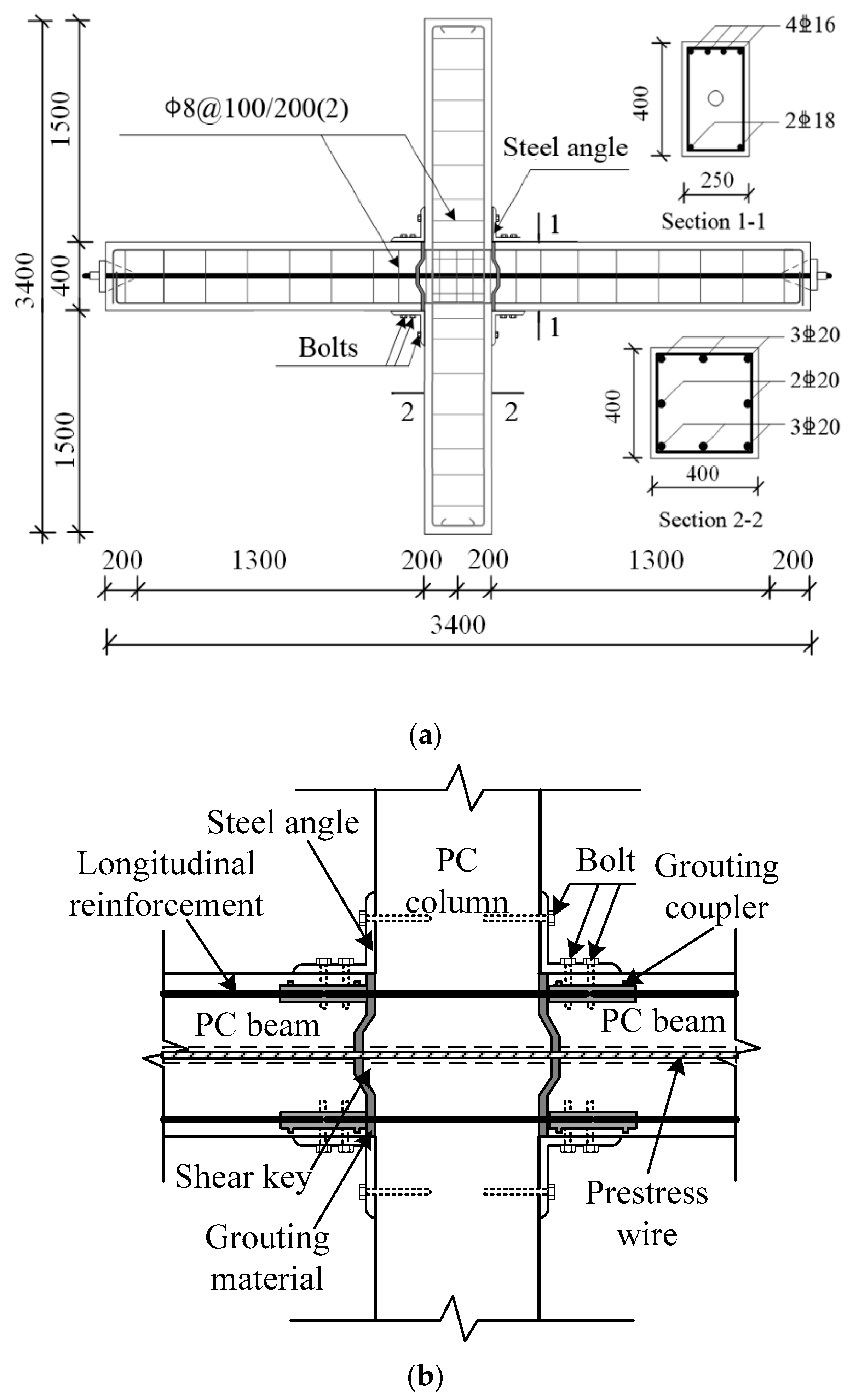
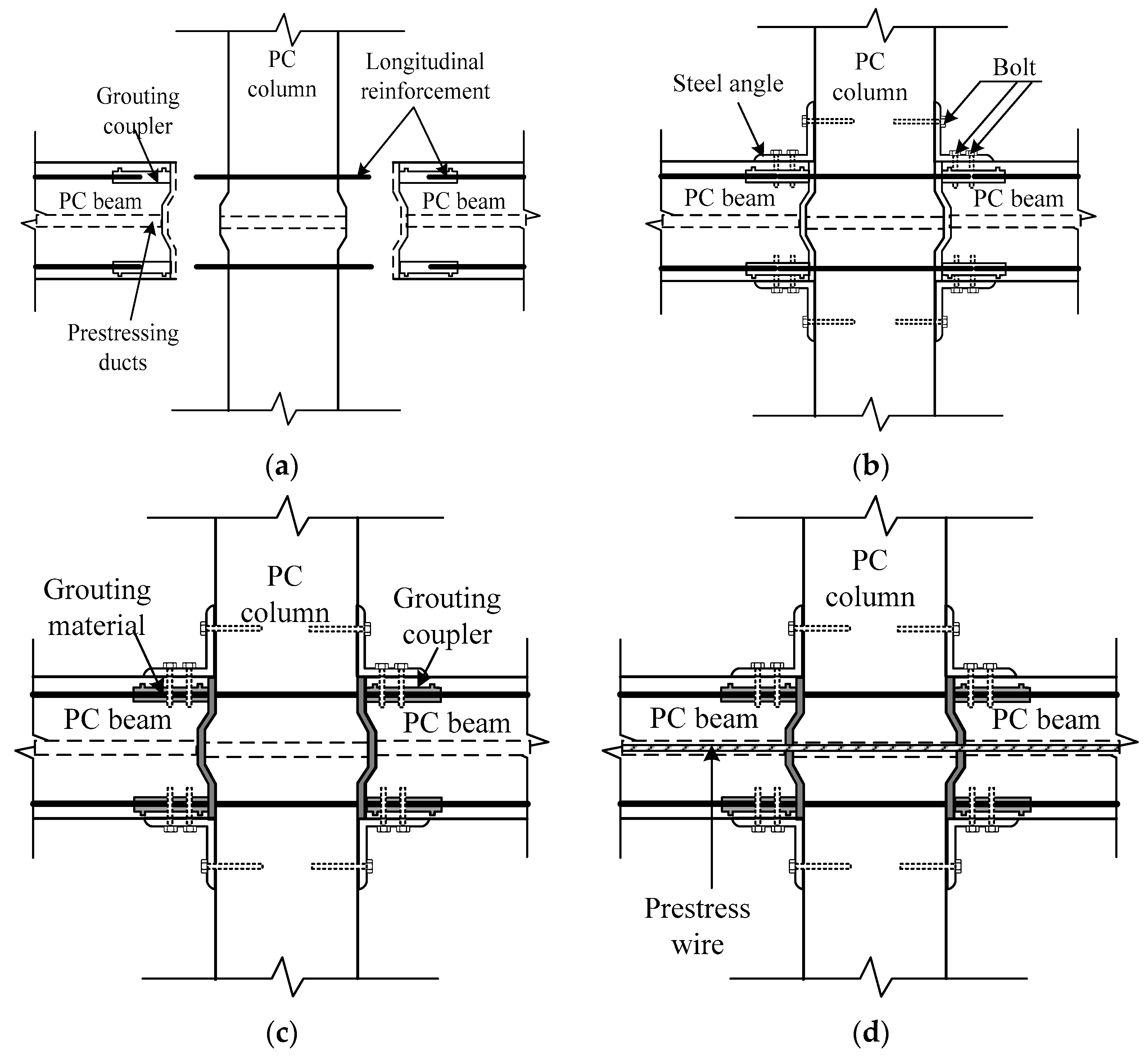
2.1. Conceptual Design of Hybrid Connection

Two frame connections were designed based on the Chinese Code for Seismic Design of Buildings (GB 50011-2010): a novel HPC connection and another monolithic PC connection. The cross-section of the column member was 400 × 400 mm and its height was 3000 mm, while the cross-section of the beam member was 250 × 400 mm and its length was 3400 mm, as shown in Figure 1. For the HPC connection, the grouting couplers were fixed with steel rebars and embedded in the prefabricated beam members. Three 1860 grade high-strength prestress wires with a diameter of 15.2 mm were placed in the corrugated duct, which had a diameter of 50 mm. Steel angles of L160 × 160 × 10 were used in the beam–column connection regions. All the steel angles were bolted using high-strength bolts, 20 mm in diameter.
The detailed procedures for the proposed HPC frame connection are illustrated in Figure 2. Specifically, the prefabricated beam and column members were located and assembled with steel angles (Figure 2a,b), and then the longitudinal rebars in the beam members could be connected using grouting non-shrinkage high-strength mortar into the corrugated duct (Figure 2c). Finally, the prestress wires were tensioned in the corrugated duct and anchored at the tendons (Figure 2d). The specific post-tensioning construction of the tendons is shown in Figure 3. The post-tensioned techniques consisted of three steps: embedding of the corrugated duct and tensioning and anchoring of the prestress wires.
As the control, the code-defined monolithic PC connection was designed following the Technical Specification for Prefabricated Concrete Structures (China JGJ 1-2014). The design dimensions and reinforcement of the PC connection are illustrated in Figure 4. The dimensions of PC frame connection were the same as the HPC frame connection. The significant difference between the two connections was the post-casting belt in the beam and connection core zone. The assembly process of the PC connection is shown in Figure 5. The longitudinal rebars at the bottom of the beam members were connected first with grouting couplers (Figure 5a), and then the secondary pouring of concrete was performed in the connection core zone after the upper longitudinal rebars were bounded (Figure 5b). Next, the upper prefabricated column was installed and fixed with the grouting couplers. Finally, the shrinkage-resistant high-strength grouting material was poured at the interface between the column and the connection (Figure 5c).

2.2. Material Properties

Following the Standard for Test Methods for Mechanical Properties of Ordinary Concrete (China GB/T50081-2002), tests were carried out on each group of three 150 mm × 150 mm × 150 mm cubic concrete blocks. The compressive strengths of the prefabricated concrete, cast in situ concrete, and high-strength grouting material were identified as 40.8, 40.3, and 61.3 MPa, respectively. Table 1 lists the mechanical properties of the steel bars, including the yield strength, ultimate strength, and elastic modulus. The yield and ultimate strengths of the Q235 steel plate were 281.5 MPa and 347.0 MPa, respectively.

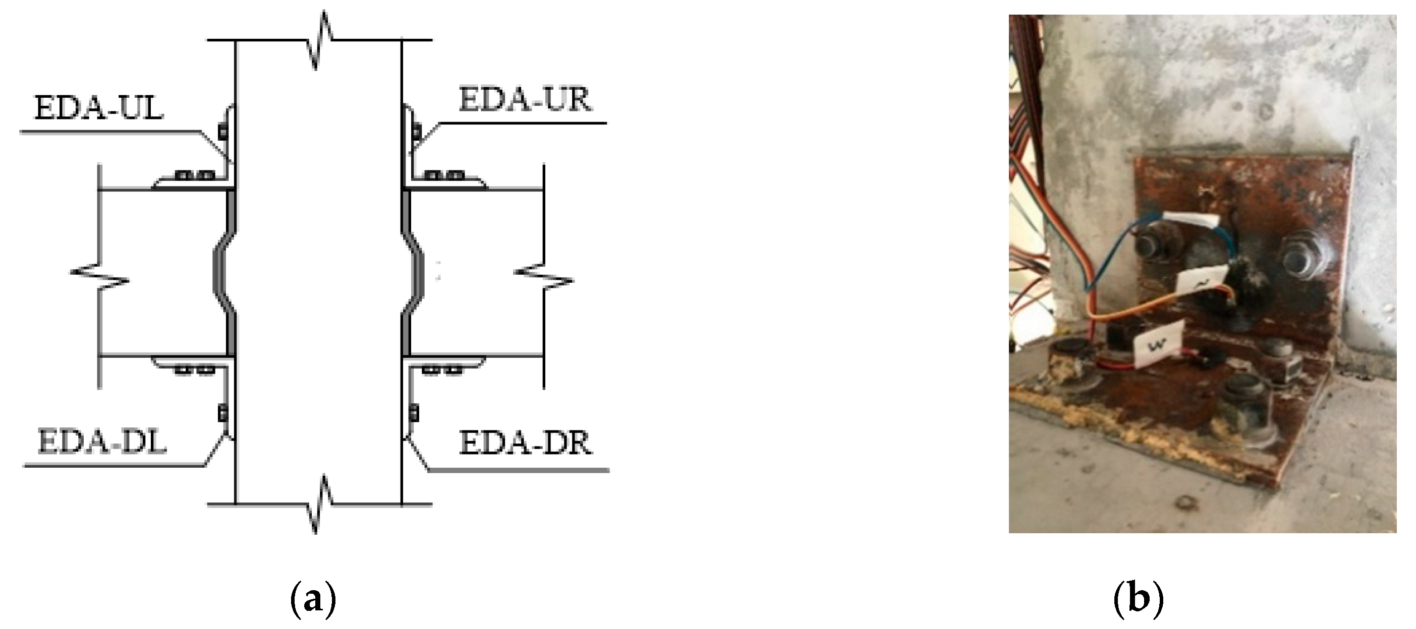
2.3. Test Setup and Loading Program

Figure 6 shows an illustration and photographs of the test setup for the connection specimens. Each of the test connection specimens was subjected to cyclic loading that simulated earthquake loading. The prefabricated column was pinned to the strong floor and steel frame. The end of the beam was connected to the steel frame by steel links that permitted rotation and free horizontal movement in the beam, but restricted vertical movement. A 1000 kN capacity lifting jack was connected on top of the column to apply the constant axial load. Two 500 kN capacity vertical actuators were installed on the beam end to apply the displacement-controlled cyclic load.
The axial compression load on the top of the column was set as 0.2. Two vertical actuators asymmetrically applied cyclic load at both beam ends, while the axial load on the column remained constant. The displacement-controlled cyclic loading history is shown in Figure 7. The applied loads and displacement response were accurately measured by transducers in the hydraulic servo-control actuator. Moreover, strain gauges attached on the longitudinal steel bars, stirrups and steel angles in the connection were used to monitor the rebar strain during the test. The tests of the specimens were terminated when the bearing capacity decreased to 85% of the peak load.

3. Experimental Results

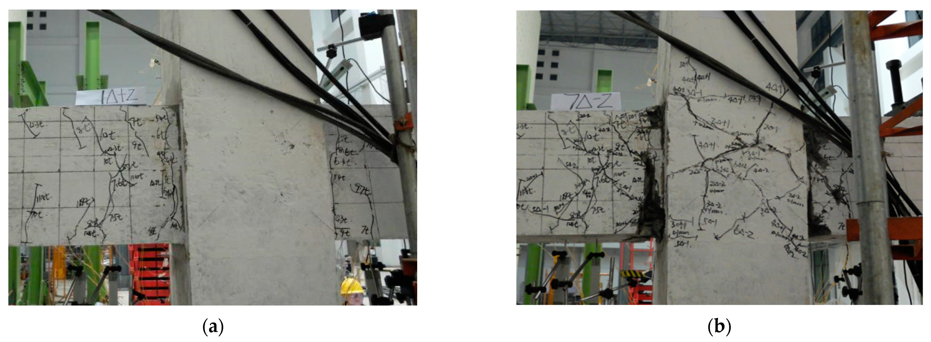
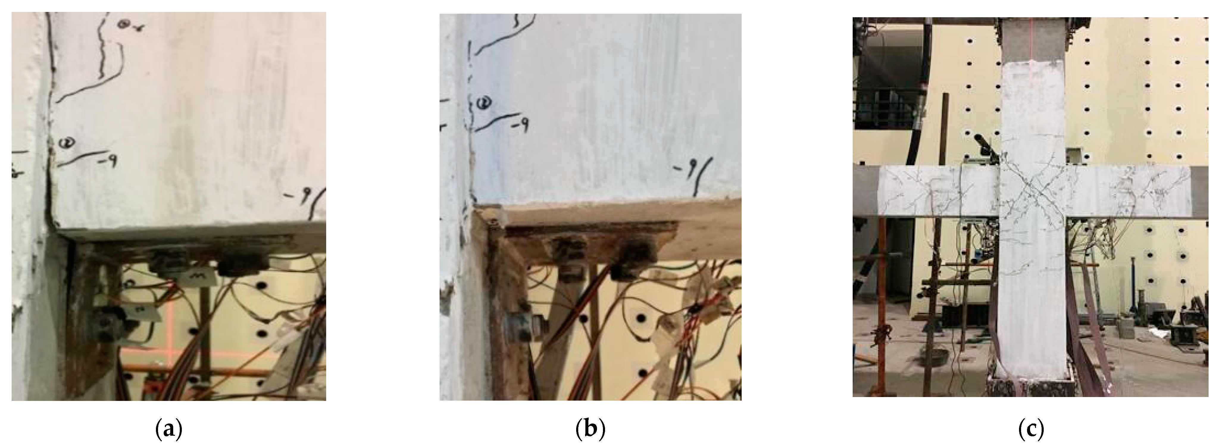
3.1. Crack Pattern and Failure Mode

The crack patterns and failure modes of these specimens are illustrated in Figure 8 and Figure 9, respectively. For the PC connection, a flexural crack 0.02 mm in width developed at the intersection of the beam and column regions (i.e., the potential plastic hinge), with the displacement of vertical actuators reaching 3 mm. When the yielding of the longitudinal rebar initially appeared, with a displacement of up to 9 mm (i.e., Δy = 9 mm), several flexural cracks 0.15 mm in width propagated through the plastic hinge (Figure 8a). Then, a few diagonal cracks appeared in the connection core zone, with the vertical displacement reaching 3Δy, and they further propagated along the diagonal directions. When the displacement increased to 5Δy, the concrete started to spall off at the bottom of the beam and the shear cracks along the diagonal direction expanded to 2.3 mm. Finally, the concrete at the top of the beam began to become crushed with the stirrups exposed, and an obvious diagonal compression structure at a displacement of 7Δy was formed (Figure 8b). At this stage, the connection experienced a substantial reduction in strength, until it reached 85% of the peak load.
For the HPC connection, the first flexural crack of 0.01 mm in width formed at the intersection of the beam and column, with the displacement reaching 6 mm. When the longitudinal rebar yielded at the displacement of 10 mm (i.e., Δy = 10 mm), a few vertical cracks appeared at the top and bottom of the beam with 0.05 mm widths (Figure 9a). At the displacement of 3Δy, the cracks at the interface of the beam connection were partially closed due to the retraction of the prestressed steel strand (Figure 9b). It should be noted that the cracks in HPC connection underwent opening and closure under cyclic loading due to the post-tensioned wires. Two diagonal cracks appeared gradually in the connection core zone at a displacement of 5Δy. The shear crack expanded along the diagonal direction by only approximately 0.75 mm. Another obvious difference between the HPC and PC connections was that the cracking of the HPC connection was narrower, which highlighted the contributions of the post-tensioning technique to cracking control. The connection failed at the displacement of 7Δy due to a small amount of spalling of concrete in the connection core zone and the bucking of the steel angles (Figure 9c).

3.2. Hysteresis Curve

The shear force versus displacement of hysteresis loops of the HPC and PC connection is shown in Figure 10. During the initial cycles, the PC connection performed an elastic behavior in hysteresis loops. With the displacement in the loading cycles up to 9 mm, the connection attained the initial yield with the corresponding shear force reaching 105.2 kN. In the subsequent loading cycle corresponding to 18 mm, the connection reached the maximum capacities of 115.3 kN in the positive loading direction and 140.6 kN in negative loading direction, respectively. Afterwards, the connection experienced the stiffness degradation and performed a significant pinching behavior. The test was terminated at the displacement of 63 mm, and the connection reached the residual capacity of 90.3 kN.
The shear force versus displacement hysteresis loops for the HPC connection can be compared as a further analysis. In the positive loading direction, the initial yield of the HPC connection occurred at the displacement of 10 mm, with the shear force reaching 112.6 kN. The maximum capacities—175.6 kN in the positive and 176.1 kN in the negative loading directions—were reached at displacements of 45 mm and 36 mm, respectively. In the positive direction, the maximum capacity of the HPC connection was 52% larger than that of PC connection, while the difference in the negative direction was 25%. Before reaching the maximum capacities, hardening phenomena in the shear force were identified, which implied contributions from the steel angles to the bearing capacity. These phenomena suggested that the hybrid connection improved the seismic performance in view of the bearing capacity. Steady energy dissipation in the HPC connections was observed from the hysteresis loops. After attaining the highest bearing capacity, the stiffness degradation of the connection lasted until the final residual capacity of 142.5 kN, which corresponded to 63 mm.

3.3. Envelope Curve

The envelope curves of the HPC and PC connections are shown and compared in Figure 11. Before the yielding of the longitudinal rebar in the beam member, the bearing capacities of these connections increased almost linearly with the increasing loading. Then, the bearing capacity of the PC connection decreased slightly, and the descending trend in the negative bearing capacity was faster. However, the bearing capacity of the HPC connection continued to increase obviously after the yielding of the rebar. The post-yielding behavior of the HPC connection indicated the significant contributions of the steel angles and post-tensioned wires to the improvement of the bearing capacity and the stiffness of the connection. After reaching the peak load, mild degradation of the bearing capacity was observed, as opposed to a more obvious decrease in the negative bearing capacity. In the final loading stage, the yielding of the steel angles and the longitudinal rebar in the plastic hinge occurred in the HPC connection, but the yielding did not appear in the prestressed strand. As long as the strands remained elastic, the HPC connection was able to keep self-centering upon the unloading process.

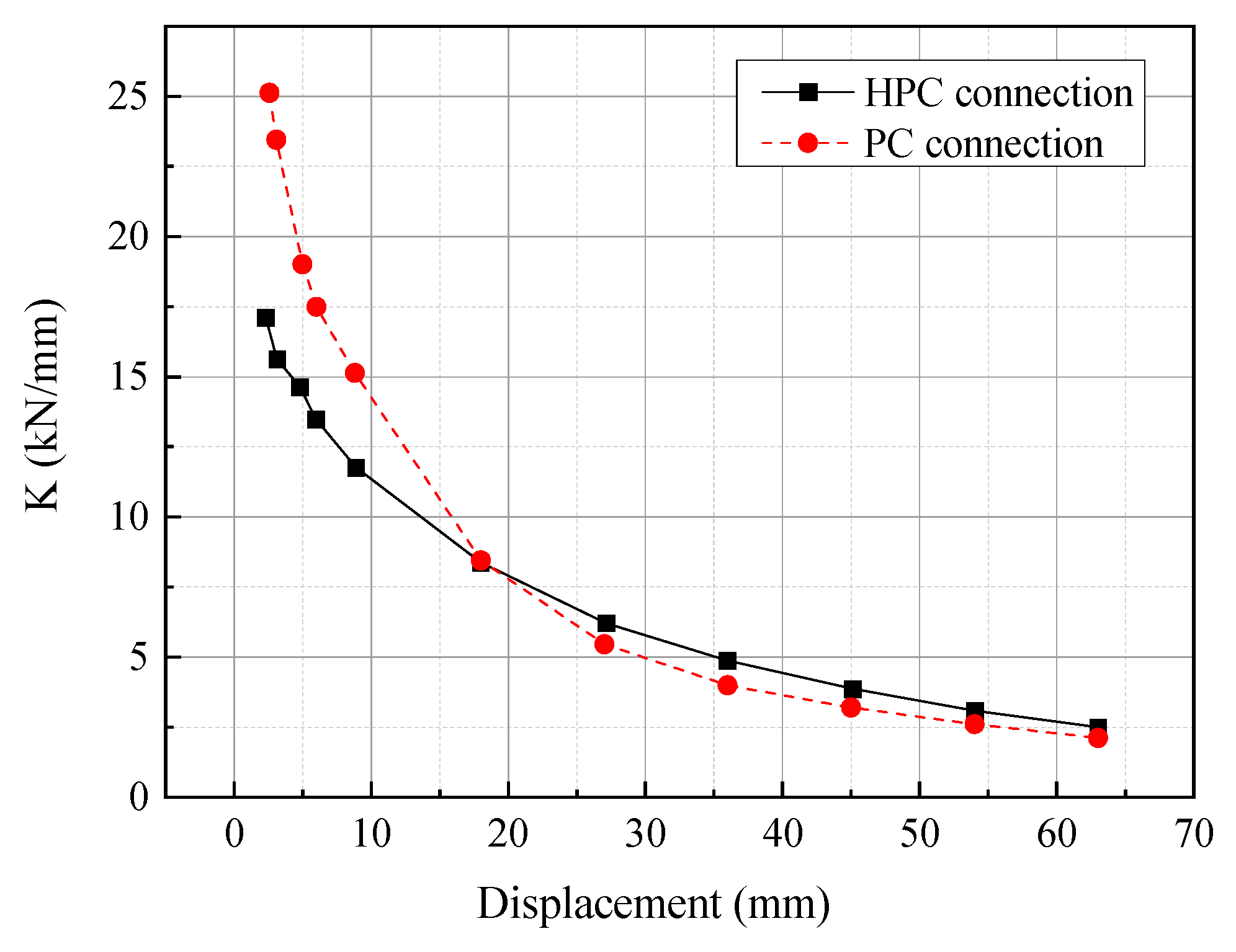
3.4. Ductility and Stiffness Degradation

Ductility is another vital parameter for seismic capacity that reflects the plastic deformation ability of the structure in the post-yielding stage. The ductility coefficient μ can be quantified as the ratio of the ultimate displacement Δu to the corresponding yielding displacement Δy; i.e., μ = Δuy. Specifically, the yielding displacement for each connection can be identified by using the equivalent energy method. The ultimate displacement corresponded to the 85% peak load. The ductility coefficients of each connection are listed in Table 2. It can be seen that the ductility coefficient of the HPC connection (6.20 on average) was generally higher than that of the PC connection (5.02 on average).
The stiffness degradation behaviors in the HPC and PC connections are shown and compared in Figure 12. With the increase of the displacement level, the stiffness of these connections gradually decreased and then tended to remain steady. The stiffness degradation curves for the HPC and PC connections show analogous trends, but the stiffness degradation rates were different. The stiffness degradation rate of the PC connection, due to the cracking and spalling of the concrete, was obviously higher than that of HPC connection, especially in the post-yielding stage. During the loading process, the initial stiffness of the PC connection was higher than that of the HPC connection. After the connection yielding, the HPC connection could provide more stiffness than the PC connection, which demonstrated that the prestressed strands could affect the overall stiffness degradation of the connection.

3.5. Energy Dissipation Capacity

The energy dissipation capacity of the connections was obtained based on the areas enclosed by their hysteresis curves. The cumulative energy dissipation versus the displacement is shown in Figure 13. Obviously, the energy dissipation characteristics of the two specimens show nonlinear increasing trends, varying with the increasing displacement. At the initial loading stage, the energy dissipation of the HPC connection was limited. With increasing displacement, the energy dissipation capacity of the HPC connection sharply increased with the development of plastic deformation in the steel angles and rebars. The results indicated that the PC connection had slightly higher (10% on average) energy dissipation compared to the HPC connection.

4. Discussion

4.1. Energy Dissipation of Steel Angles

The steel angles play a critical role in transferring the column load and moment to the beam. In order to understand the contributions of the steel angles to the bearing capacity and energy dissipation capacity, three strain gauges were distributed for each steel angle, as shown in Figure 14. Consequently, the tensile strength–displacement curves of the steel angles at the four measured points were obtained, as shown in Figure 15. The tensile strength at the bottom steel angles is generally higher than that at the upper steel angles. Specifically, the tensile strength of EDA-UR can reach 542.3 kN compared to a value of 366.9 kN for EDA-DR. The corresponding deformation of the steel angles is 1.75 mm. It was found that the stiffness of the steel angles reduced gradually and Bauschinger effects appeared with the strain hardening, which demonstrated the anticipated inelastic behavior of the steel angles [34]. Furthermore, the plumpness of the hysteretic curve can be used to calculate the energy dissipation of the steel angles [35]. It can be concluded that all the steel angles had good plumpness in their hysteretic curves and presented excellent energy dissipation capacities.
The energy dissipation results for the upper steel angles (EDA-U) at each loading step are listed in Table 3. It can be seen that the contribution of the steel angles to the total energy dissipation in the connection increased slightly, up to 18.7%, before connection yielding. Then, the percentage for the contribution of the steel angles to connection energy dissipation showed a rapid increase and even reached 84.2%, with this proving to be the dominant role of the steel angles in the energy dissipation in the connection. Table 3 reinforces the earlier observation that more energy can be dissipated with the use of thicker steel angles [36].

4.2. Variation in Prestressing Force

The prestressing force at the PT tendon versus the displacement of vertical actuator is shown in Figure 16. The initial prestressing force after the prestressing wires were tensioned was 361.3 kN. Due to the anchorage retraction at the initial loading steps and limited cracking in the high-strength grouting material, a loss in the prestressing force occurred, with its maximum value reaching 19.2 kN, only 5.31% of the initial value. Thus, the prestressing force varied within the elastic range (up to 170.1 kN) during the cyclic loading process. It was demonstrated that the prestressing force remained elastic, with negligible losses in the prestressing force during the cyclic loading steps. This ensured the connection had sufficient stiffness and restoring capacity to undergo large nonlinear displacements without crushing of the concrete [12,37].

4.3. Deformation Capacity

The deformation capacity can be evaluated in terms of the residual displacement and residual rotation at the beam end. The residual deformation rate αrd can be calculated as follows:
α r d = Δ rd Δ max
where Δrd and Δmax are the residual displacement and maximum displacement, respectively, applied at the beam end. The residual rotation rate βrd can be obtained as follows:
β r d = θ rd θ max
where θrd and θmax are the residual rotation and maximum rotation of the connection, respectively.
Table 4 lists the residual displacement and residual rotation results for the HPC connection. It can be seen that both residual displacement and residual rotation increased slightly and reached the maximum values of 9.5 mm and 0.56%, respectively. Correspondingly, the residual displacement and residual rotation were constricted to within 0.21 and 0.153, respectively. The limited residual displacement and rotation may be attributable to the pretension force and its restoring characteristics [38].
Figure 17 shows the relationship between the residual displacement Δrd and maximum displacement Δmax for these two specimens. Compared with the HPC connection, the PC connection showed a significant increase in the residual displacement, and its maximum value could reach 24.8 mm. The corresponding maximum residual deformation rate was 0.55, which was more than twice that of the HPC connection. These results indicate that the HPC connection exhibited lower residual deformation, which can minimize concrete cracking and spalling [39,40].

4.4. Applied Element Method Simulation

Numerical simulation is another efficient method used to address the problem of progressive collapse of buildings and to study the seismic performance of novel connections. Compared with the most commonly used method, the finite element method (FEM), the applied element method (AEM) can facilitate faster dynamic analysis by using the normal and shear springs to connect rigid elements in the structural model [41]. The AEM has been efficiently used in a collapse analysis for prototype reinforced-concrete (RC) frame buildings subjected to a set of 22 ground motion records [42] and in the seismic assessment of a typical four-story building for two earthquake magnitudes (0.15 g and 0.3 g) [43], among other settings. In the future, progressive collapse analyses of frame buildings with novel hybrid connections could be performed using AEM analysis. Consequently, the collapse mode, collapse direction, and damage level could be obtained. Moreover, the effectiveness of the novel hybrid connection in precast buildings in seismic regions could be demonstrated and optimized further.

5. Conclusions

A novel prefabricated hybrid connection system was developed for prefabricated beam–column connections in prefabricated concrete frame structures in seismic areas. Experimental tests were conducted on two full-scale prefabricated beam–column connections, a hybrid connection and a monolithic connection, under displacement-controlled cyclic loading. A variety of parameters for the specimens, including the hysteresis behavior, envelope loop, PT tendon resultant, residual displacement, energy dissipation capacity, ductility, and stiffness degradation, were obtained. Some major conclusions can be drawn as follows:
  • The proposed HPC connection exhibited lower cracking development, stiffness degradation, and residual displacement owing to prestressing strands, while the prestressing force remained elastic.
  • The strength and energy dissipation capacity of the HPC connection increased rapidly, and both were larger than those of the PC connection (up to 52% and 10%, respectively) during the post-yielding stage. It was demonstrated that the steel angles played a critical role in improving the seismic performance of the connections.
  • The grouting technique could efficiently realize the continuation of beam reinforcement with the minimum of cast in situ work. Thus, the proposed HPC connection has great potential for deployment in seismic regions, demonstrating excellent seismic performance and efficient construction techniques.

Author Contributions

W.C.: methodology, conceptualization, writing—review & editing, funding acquisition; Y.X.: experiment, writing—original draft; X.G.: supervision, investigation, review & editing; D.L.: methodology, writing—review & editing, correspondence. All authors have read and agreed to the published version of the manuscript.

Funding

The research reported in this paper was supported by the Scientific Research Founding of Key Laboratory of Building Collapse Mechanism and Disaster Prevention, China Earthquake Administration (Grant No. FZ211106).

Institutional Review Board Statement

Not applicable.

Informed Consent Statement

Not applicable.

Data Availability Statement

The data presented in this study are available on request from the authors.

Conflicts of Interest

The authors declare no conflict of interest.

References

  1. Polat, G. Prefabricated concrete systems in developing vs. industrialized countries. Civil Eng. Manage. 2010, 16, 85–94. [Google Scholar] [CrossRef]
  2. Deng, E.F.; Lian, J.Y.; Liu, Z.; Zhang, G.C.; Wang, S.B.; Cao, D.B. Compressive behavior of a fully prefabricated liftable connection for modular steel construction. Buildings 2022, 12, 649. [Google Scholar] [CrossRef]
  3. Yan, X.Y.; Wang, S.G.; Huang, C.Y.; Hong, C. Experimental study of a new precast prestressed concrete joint. Appl. Sci. 2018, 10, 1871. [Google Scholar] [CrossRef]
  4. Lacey, A.W.; Chen, W.; Hao, H.; Bi, K. Review of bolted inter-module connections in modular steel buildings. J. Build. Eng. 2019, 23, 207–219. [Google Scholar] [CrossRef]
  5. Nadeem, G.; Safiee, N.A.; Bakar, N.A.; Karim, I.A.; Nasir, N.A.M. Connection design in modular steel construction: A review. Structures 2021, 33, 3239–3256. [Google Scholar] [CrossRef]
  6. Campbell, R.D.; Griffin, M.J.; Bragagnolo, L.J.; Yanev, P.I. The 7 December 1988 Armenia Earthquake Effects on Selected Power, Industrial and Commercial Facilities; IAEA: Vienna, Austria, 1996. [Google Scholar]
  7. Marzo, A.; Marghella, G.; Indirli, M. The Emilia-Romagna earthquake: Damages to precast/prestressed reinforced concrete factories. Ing. Sismica 2012, 29, 132–147. [Google Scholar]
  8. Negro, P.; Bournas, D.A.; Molina, F.J. Pseudodynamic tests on a full-scale 3-storey prefabricated concrete building: Global response. Eng. Struct. 2013, 57, 594–608. [Google Scholar] [CrossRef]
  9. Mohammed, K.; Jameel, M.; Ibrahim, Z.; Tan, C.G. Performance of a ductile hybrid post-tensioned beam-to-column connection for precast concrete frames under seismic loads: A review. Appl. Sci. 2021, 11, 7497. [Google Scholar] [CrossRef]
  10. Rodríguez, M.E.; Torres-Matos, M. Seismic behavior of a type of welded prefabricated concrete beam-column connection. PCI J. 2013, 358, 81–94. [Google Scholar] [CrossRef]
  11. Deng, K.L.; Peng, P.; Lam, A.; Pan, Z.H.; Ye, L.P. Test and simulation of full-scale self-centering beam-to-column connection. Earthq. Eng. Eng. Vib. 2013, 4, 98–106. [Google Scholar] [CrossRef]
  12. Lago, B.D.; Negro, P.; Lago, A.D. Seismic design and performance of dry-assembled precast structures with adaptable joints. Soil Dyn. Earthq. Eng. 2018, 106, 182–195. [Google Scholar] [CrossRef]
  13. Guerrero, H.; Rodriguez, V.; Escobar, J.A.; Alcocer, S.M.; Bennetts, F.; Suarez, M. Experimental tests of precast reinforced concrete beam-column connections. Soil Dyn. Earthq. Eng. 2019, 125, 105743. [Google Scholar] [CrossRef]
  14. Ding, K.; Ye, Y.; Ma, W. Seismic performance of prefabricated concrete beam-column joint based on the bolt connection. Eng. Struct. 2021, 232, 111884. [Google Scholar] [CrossRef]
  15. Li, B.; Kulkarni, S.A.; Leong, C.L. Seismic performance of precast hybrid-steel concrete connections. J. Earthq. Eng. 2009, 13, 667–689. [Google Scholar] [CrossRef]
  16. Cavaco, E.; Pacheco, I.; Camara, J. Detailing of concrete-to-concrete interfaces for improved ductility. Eng. Struct. 2018, 156, 210–223. [Google Scholar] [CrossRef]
  17. Choi, H.K.; Choi, Y.C.; Choi, C.S. Development and testing of precast concrete beam-to-column connections. Eng. Struct. 2013, 56, 1820–1835. [Google Scholar] [CrossRef]
  18. Parastesh, H.; Hajirasouliha, I.; Ramezani, R. A new ductile moment-resisting connection for precast concrete frames in seismic regions: An experimental investigation. Eng. Struct. 2014, 70, 144–157. [Google Scholar] [CrossRef]
  19. Chen, Y.; Zhang, Q.; Feng, J.; Zhang, Z. Experimental study on shear resistance of precast RC shear walls with novel bundled connections. J. Earthq. Tsunami 2019, 13, 1940002. [Google Scholar] [CrossRef]
  20. Ma, W.C. Behavior of Aged Reinforced Concrete Columns under High Sustained Concentric and Eccentric Loads; University of Nevada: Las Vegas, NV, USA, 2021. [Google Scholar]
  21. Ma, W.C. Simulate Initiation and Formation of Cracks and Potholes; Northeastern University: Boston, MA, USA, 2016. [Google Scholar]
  22. Esmaeili, J.; Ahooghalandary, N. Introducing an easy-install prefabricated concrete beam-to-column connection strengthened by steel box and peripheral plates. Eng. Struct. 2020, 205, 110006. [Google Scholar] [CrossRef]
  23. Dhanapal, J.; Ghaednia, H.; Das, S.; Velocci, J. Structural performance of state-of-the-art VectorBloc modular connector under axial loads. Eng. Struct. 2019, 183, 496–509. [Google Scholar] [CrossRef]
  24. Lima, J.M.; Bezerra, L.M.; Bonilla, J.; Barbosa, W.C.S. Study of the behavior and resistance of right-angle truss shear connector for composite steel concrete beams. Eng. Struct. 2022, 253, 113778. [Google Scholar] [CrossRef]
  25. Senturk, M.; Pul, S.; Ilki, A.; Hajirasouliha, I. Development of a monolithic-like prefabricated beam-column moment connection: Experimental and analytical investigation. Eng. Struct. 2020, 205, 110057. [Google Scholar] [CrossRef]
  26. Moghadasi, M.; Marsono, A.K.; Mohammadyan-Yasouj, S.E. A study on rotational behaviour of a new industrialised building system connection. Steel Compos. Struct. 2017, 25, 245–255. [Google Scholar]
  27. Song, B.X.; Xu, W.Z.; Du, D.S.; Wang, S.G.; Li, W.W.; Zhang, Y.L. Seismic design of hybrid unbonded post-tensioned prefabricated concrete joints based on bearing capacity and energy dissipation capacity. Adv. Struct. Eng. 2021, 24, 1724–1738. [Google Scholar] [CrossRef]
  28. Wang, J.H. Cyclic behaviors of reinforced concrete beam-column joints with debonded reinforcements and beam failure: Experiment and analysis. Bull. Earthq. Eng. 2021, 19, 101–133. [Google Scholar] [CrossRef]
  29. Huang, L.J.; Zhou, Z.; Huang, X.G.; Wang, Y.W. Variable friction damped self-centering precast concrete beam-column connections with hidden corbels: Experimental investigation and theoretical analysis. Eng. Struct. 2020, 206, 110150. [Google Scholar] [CrossRef]
  30. Huang, W.; Hu, G.; Miao, X.; Fan, Z. Seismic performance analysis of a novel demountable precast concrete beam-column connection with multi-slit devices. J. Build. Eng. 2021, 44, 102663. [Google Scholar] [CrossRef]
  31. Li, Y.; Geng, F.; Ding, Y.; Wang, L. Influence of mild steel damper design parameters on energy dissipation performance of low-damage self-centering precast concrete frame connections. Soil Dyn. Earthq. Eng. 2021, 144, 106696. [Google Scholar] [CrossRef]
  32. Gioiella, L.; Tubaldi, E.; Gara, F.; Dezi, L.; Dall’Asta, A. Modal properties and seismic behaviour of buildings equipped with external dissipative pinned rocking braced frames. Eng. Struct. 2018, 172, 807–819. [Google Scholar] [CrossRef]
  33. Zhou, X.; Ke, K.; Yam, M.C.; Zhao, Q.; Huang, Y.; Di, J. Shape memory alloy plates: Cyclic tension-release performance, seismic applications in beam-to-column connections and a structural seismic demand perspective. Thin-Walled Struct. 2021, 167, 108158. [Google Scholar] [CrossRef]
  34. Wang, W.; Chan, T.M.; Shao, H.L. Seismic performance of beam-column joints with SMA tendons strengthened by steel angles. J. Constr. Steel Res. 2015, 109, 61–71. [Google Scholar] [CrossRef]
  35. Jiang, R.; Su, X. Comparative study on empirical plastic hinge length formulas. Ind. Construct. 2008, 38, 425–430. [Google Scholar]
  36. Eom, T.S.; Cho, S.R.; Lim, J.J. Behavior of end plate connection for steel angles. Eng. Struct. 2022, 252, 113714. [Google Scholar] [CrossRef]
  37. Hwang, J.H.; Choi, S.H.; Lee, D.H.; Kim, K.S.; Kwon, O.S. Seismic behavior of post-tensioned precast concrete beam-column connections. Mag. Concrete Res. 2021, 73, 433–447. [Google Scholar] [CrossRef]
  38. Xin, G.T.; Xu, W.B.; Wang, J.; Yan, X.Y.; Chen, Y.J.; Yan, W.M.; Li, J.G. Seismic performance of fabricated concrete piers with grouted sleeve joints and bearing-capacity estimation method. Structures 2021, 33, 169–186. [Google Scholar] [CrossRef]
  39. Kwan, W.P.; Billington, S.L. Unbonded posttensioned concrete bridge piers. I: Monotonic and cyclic analyses. J. Bridge Eng. 2003, 8, 92–101. [Google Scholar] [CrossRef]
  40. Kwan, W.P.; Billington, S.L. Unbonded posttensioned concrete bridge piers. II: Seismic analyses. J. Bridge Eng. 2003, 8, 102–111. [Google Scholar] [CrossRef]
  41. Meguro, K.; Tagel-Din, H. Applied element method for structural analysis: Theory and application for linear mateirals. J. Struct. Eng. 2000, 17, 21–35. [Google Scholar] [CrossRef]
  42. Sediek, O.A.; El-Tawil, S.; McCormick, J. Seismic Debris Field for Collapsed RC Moment Resisting Frame Buildings. J. Struct. Eng. 2021, 147, 04021045. [Google Scholar] [CrossRef]
  43. Fathalla, E.; Salem, H. Parametric Study on Seismic Rehabilitation of Masonry Buildings Using FRP Based upon 3D Non-Linear Dynamic Analysis. Buildings 2018, 8, 124. [Google Scholar] [CrossRef]
Figure 1. Design dimensions and reinforcement of the HPC connection: (a) details of the dimensions and reinforcement of the HPC connection; (b) details of the HPC connection.
Buildings 12 00801 g001
Figure 2. Assembly process for the HPC connection: (a) locations of the beam and column; (b) connection assembly; (c) grouting curing; (d) prestress tension.
Buildings 12 00801 g002
Figure 3. Post-tensioning tendon construction: (a) embedding corrugated duct; (b) prestress wire tensioning; (c) prestress wire anchorage.
Buildings 12 00801 g003
Figure 4. Design dimensions and reinforcement of PC connection.
Buildings 12 00801 g004
Figure 5. Assembly process for PC connection: (a) locations of beam and column; (b) secondary pouring; (c) grouting curing.
Buildings 12 00801 g005
Figure 6. Illustration and photographs of the experimental setup: (a) illustration of the experimental setup; (b) photographs of the experimental setup.
Buildings 12 00801 g006
Figure 7. Cyclic displacement-controlled loading history.
Buildings 12 00801 g007
Figure 8. Crack pattern and failure mode of the PC connection: (a) crack at the beam end; (b) failure mode of the PC connection.
Buildings 12 00801 g008
Figure 9. Crack pattern and failure mode of the HPC connection: (a) opening of crack; (b) closure of crack; (c) failure mode.
Buildings 12 00801 g009
Figure 10. Hysteresis curves.
Buildings 12 00801 g010
Figure 11. Envelope curves.
Buildings 12 00801 g011
Figure 12. Curves for the stiffness degradation.
Buildings 12 00801 g012
Figure 13. Energy dissipation with displacement.
Buildings 12 00801 g013
Figure 14. Illustration and photograph of strain gauges: (a) strain gauge position; (b) photograph.
Buildings 12 00801 g014
Figure 15. Displacement-strain curves for the steel angles: (a) EDA-UL; (b) EDA-UR; (c) EDA-DL; (d) EDA-DR.
Buildings 12 00801 g015
Figure 16. Prestressing force.
Buildings 12 00801 g016
Figure 17. Displacement residual deformation rate.
Buildings 12 00801 g017
Table 1. The mechanical properties of the steel bars.
Diameter (mm)81820Φ s 15.2
Area (mm2)50.2254.3314139
Yield strength (MPa)3104024031720
Ultimate strength (MPa)4045405301912
Elastic modulus (MPa)2.01 × 1052.11 × 1051.99 × 1051.95 × 105
Table 2. Ductility coefficients of the connections.
SpecimenLoad Cycle DirectionΔyΔuμ μ ¯
HPC connection+8.556.26.616.20
−9.5−55.15.80
PC connection+5.833.75.815.02
−6.7−28.54.23
Table 3. Energy dissipation capacities of the steel angles.
Δ (mm)EDA-U (kN·mm)E0 (kN·mm)PP (%)
−ΔTotal
31.180.952.1337.635.7
69.128.8717.99142.4812.6
928.6626.5355.19294.6318.7
18181.15179.89361.041411.1125.6
27333.58278.88612.462679.822.9
36985.95927.311913.264052.5447.2
451626.521889.083515.605263.2566.8
542362.642451.584814.225766.3783.5
632831.153104.835935.987047.2884.2
Table 4. Residual displacement and rotation in the HPC connection.
Δ (mm)Δrd (mm)Δmax (mm)θrd (%)θmax (%)Δrdmaxθrdmax
30.53.20.040.530.160.083
61.16.30.101. 070.170.097
91.89.50.171.600.180.106
183.317.90.312.130.180.144
274.227.80.392.670.150.148
367.336.40.483.200.200.150
459.545.50.563.660.210.153
Publisher’s Note: MDPI stays neutral with regard to jurisdictional claims in published maps and institutional affiliations.

