Article

Effect of External Tendon Profile on Improving Structural Performance of RC Beams

1
Structural Engineering Department, Zagazig University, Zagazig 44519, Egypt
2
Faculty of Civil Engineering, Technical University of Košice, 04200 Košice, Slovakia
*
Author to whom correspondence should be addressed.
Buildings 2022, 12(6), 789; https://doi.org/10.3390/buildings12060789
Submission received: 1 May 2022 / Revised: 22 May 2022 / Accepted: 26 May 2022 / Published: 9 June 2022

Abstract

:
The objective of the research is to improve the structural behavior of reinforced concrete (RC) T–beams by applying various techniques of external pre-stressing tendons, thus enhancing the load-carrying capacities and raising the resistance to applied forces. Seven identical RC T–beams were subjected to four-point loading to study the influence of the deviator number, tension mechanism, and tendon profile on flexural behavior. Of these, one beam was an original specimen without any tendons. The other six beams were strengthened with external tendons: two identical specimens with straight–line tendons but with a different number of inner deviators; two identical specimens with V–shaped tendons but with a different tension direction; and finally, two identical specimens with U–shaped tendons but with a different tension direction. The results and discussion were achieved using finite element (FE) software, ANSYS WORKBENCH. The results from all specimens were listed and analyzed for the failure mechanism, load-carrying capacity, deflection, and ductility. According to the FE results, external tendons greatly enhance the load-carrying and stiffness of RC beams. In addition, strengthening beams with external pre-stressing techniques can delay the early cracking load, yield load, and ultimate load by approximately 250%, 570%, and 30%, respectively, when compared to an unstrengthened beam. Moreover, the straight-line tendon with inner deviators was obtained to be the most effective technique for simple beams.

1. Introduction

Except at anchorages and deviation joints, tendons in an external pre-stressed system are placed outside of the structural concrete dimensions. An externally pre-stressed cable is defined as a post-tensioned cable. Existing structures that have to be strengthened for a variety of reasons can benefit from external tendons. External tendons can run directly among anchorages via blocks as deviators to form harped profiles (V-shaped or U-shaped) [1]. External post-tensioning is also a viable option for new structures such as buildings and segmental bridges, particularly when using box section structures. External pre-stressed techniques might utilize plastic-sheathed or greased pre-stressing tendons (case of unbonded) or grout-filled duct. In the absence of ducts, the outer tendon is typically coated with a fire-resistant material, such as metal lath and plaster.
External steel tendons were originally used in the 1950s, but they have been forgotten for some time. Pre-stressing technologies using external steel cables have been commonly applied to successfully enhance existing constructions in Japan, the United States, and Switzerland during the last few decades [1,2,3,4,5]. The use of FRP materials with high corrosion resistance, high strength, and that are light weight may help to reduce the problem of environmental impacts (corrosions, fires, etc.) on exterior steel [6,7,8]. Therefore, since the early 1970s, researchers have been studying in this field. Strengthening with exterior pre-stressing was, and still is, a successful practice for both existing and future structures because of the following advantages [9,10,11,12]: smaller sectional areas being used more effectively; the simple repair of tendon corrosion protection and examination; as external tendons are only connected to the structure at the deviation and anchorage regions, friction losses are greatly reduced; the ability to control and modify tendon forces; and a thin web may be achieved since the compression area is not weakened by ducts.
External pre-stressing in various constructions has been the subject of several research studies. Ghallab A. et al. [13] proposed a simple method for calculating the increase in the stress of the external pre-stressing tendons that were used to support beams at any load. A new design technique was presented that takes the deformation of the member into account using equations for the stress calculation of unbonded tendons. The experimental investigation of the RC structural elements with exterior pre-stressing was enhanced by Zou J. et al. [1]. In the laboratory, they strengthened beams with external pre-stressing cables and tested them under vertical loads to demonstrate the effects of external pre-stressing. Kim J. et al. [14] researched how to use pre-stressing tendons to retrofit RC frames against progressive failure. They studied how exterior post-tensioning cables across slab beams affected the performance of progressive failure when the inner column in the first story was suddenly removed for the 6story case and 20-story case under dynamic and static loading. The authors found that the tendons’ cross-sectional dimension and initial tension had a beneficial impact on the structures’ retrofitting during dynamic and static loads. In addition, exterior pre-stressing could enhance the load-carrying ability of single-bay frames by 30%, according to Mahmoud et al. [15]. Following, Ghannam M. et al. [16] investigated pre-stressing wires’ influence on steel frame responses to several forms of applied loading. This research focused on the impacts of several outer pre-stressing methods for a single frame, double-story frame, and double-bay frame. To differentiate between these techniques, the profile and position of the pre-stressed cables were utilized. The results of this study indicated that each frame had a specific approach that may have increased the frame’s load-carrying ability. Furthermore, depending on the tendon eccentricity and the pre-stressing force, the authors discovered that the post-tensioned cable could increase the load capacity more than 35%. After that, numerous scholars studied the non-linear analysis of RC beams with unbonded steel tendons [17].
According to Harajli M.H. [18], this technique is more cost-effective than any other strengthening technique. According to earlier research, due to its installation speed, the low interruption to the structural user, cost-efficiency, and simplicity, exterior post-tensioning has become a successful procedure for enhancing various buildings and structures.
Many studies have been performed to show the effect of the external tendon profile on the flexural behavior of beams using experimental and analytical methods under three-point loading [4,19] or for continuous beams [20,21]. In addition, the effects of other parameters were studied in recent studies [22,23]. The use of external tendons for RC beams has reached the construction process, particularly in new constructions such as bridges, where in most cases, the beam is a box-section, providing a good opportunity for the external tendon to be inside the box, in addition to providing good contact between the RC beam and the RC/steel deviators (construction of the beam and the deviators together). Therefore, it is easy to make multi-mid-deviators, as illustrated in Figure 1. Previous research has also proven that increasing the number of inner-deviators improves the structural behavior of beams and provides a good opportunity for transferring the pre-stressed force from the external cable to the RC section along the beam span. In the case of beams that already exist, however, and that need to be strengthened for any reason, such as new safety requirements, it appears that strengthening an existing beam using an external tendon with one or more mid-deviators leads to some field-application difficulties, especially in the case of T-beams or rectangle beams. Therefore, our goal in this research is to show the effect of one or more mid-deviators on the degree of improvement in the structural behavior of a beam and to present it to the designer so that a decision can be made either to use internal deviators and benefit from them in improving the structural behavior of the beam, or to be satisfied with having them at the ends only (end anchorages at the supports).
The second goal of the research is to investigate the effects of tension directions. In the case of using RC end anchorage to strengthen the beams with external cables, the concrete section of the end anchorage covers an appropriate length of the external cable. To facilitate the tension process, it is preferable to make the cable horizontal at the ends, and this conflicts with the harped-profile of the cable when using mid-deviators to form V-shaped (one mid-deviator) or U-shaped (two mid-deviators) profiles. Therefore, this study aims to show whether there is a significant effect on the structural behavior of the beam and on the losses of the pre-stressing forces from the cable being horizontal at the ends or being left tilted at the same angle until the end.
In this research, a theoretical analysis was conducted with ANSYS WORKBENCH 19.2 (ANSYS Inc.: Canonsburg, PA, USA) [24] to study the structural responses of RC T-beams strengthened using several methods of external pre-stressed cables under four-point loading, including load bearing capacity, mechanisms of failure, ductility, and load-deflection properties. A sensitivity analysis was performed to assess the ideal technique of strengthening with external tendons that could increase the load capacities of simple T-beams. The number of deviators, outer tendon profile, and tension direction were all taken into account. Based on the ANSYS results, certain conclusions and recommendations were generated that may be utilized to guide design and application development.

2. Methodology and Programming

There are four parts in this section. The several techniques of strengthening with external tendons that have been modeled for simple RC T-beams using ANSYS WORKBENCH 19.2 are shown in the first part. Secondly, the specimen design is introduced, which contains sectional properties, sample length, and tendon characteristics. The pre-stressing process for cables and the loading technique are detailed in the third part. The final part covers model programming in ANSYS WORKBENCH 19.2.

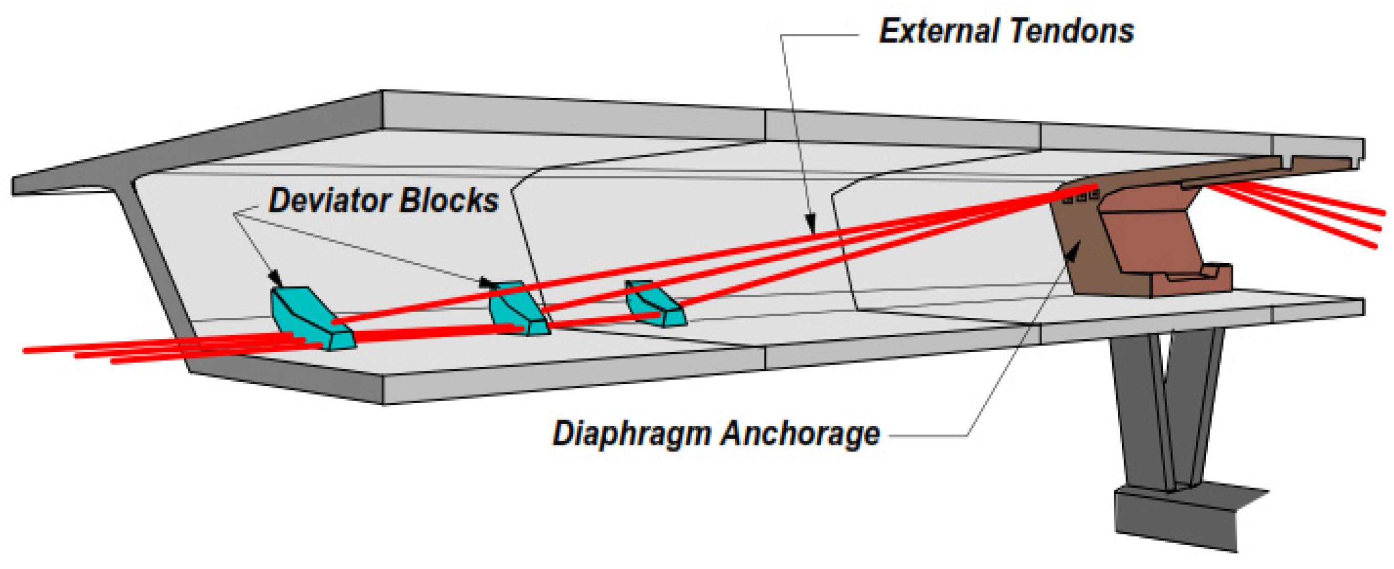
2.1. Strengthening Techniques with External Pre-Stressing
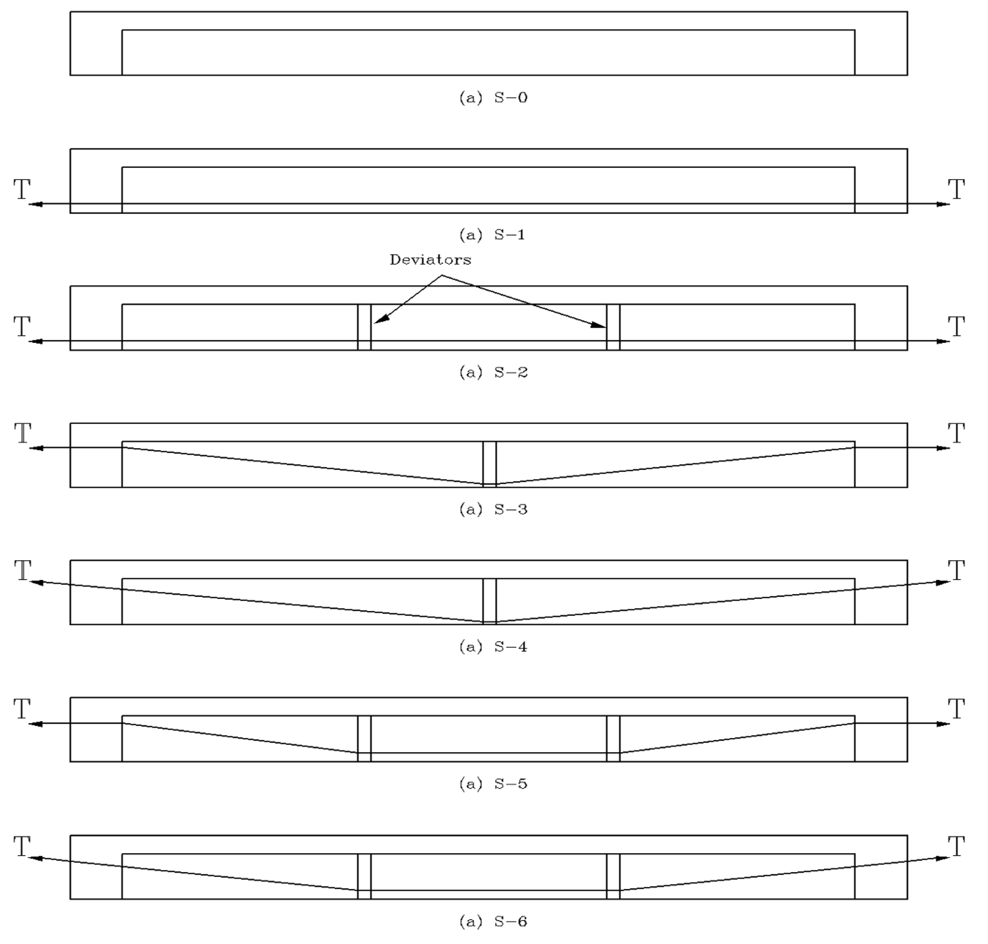
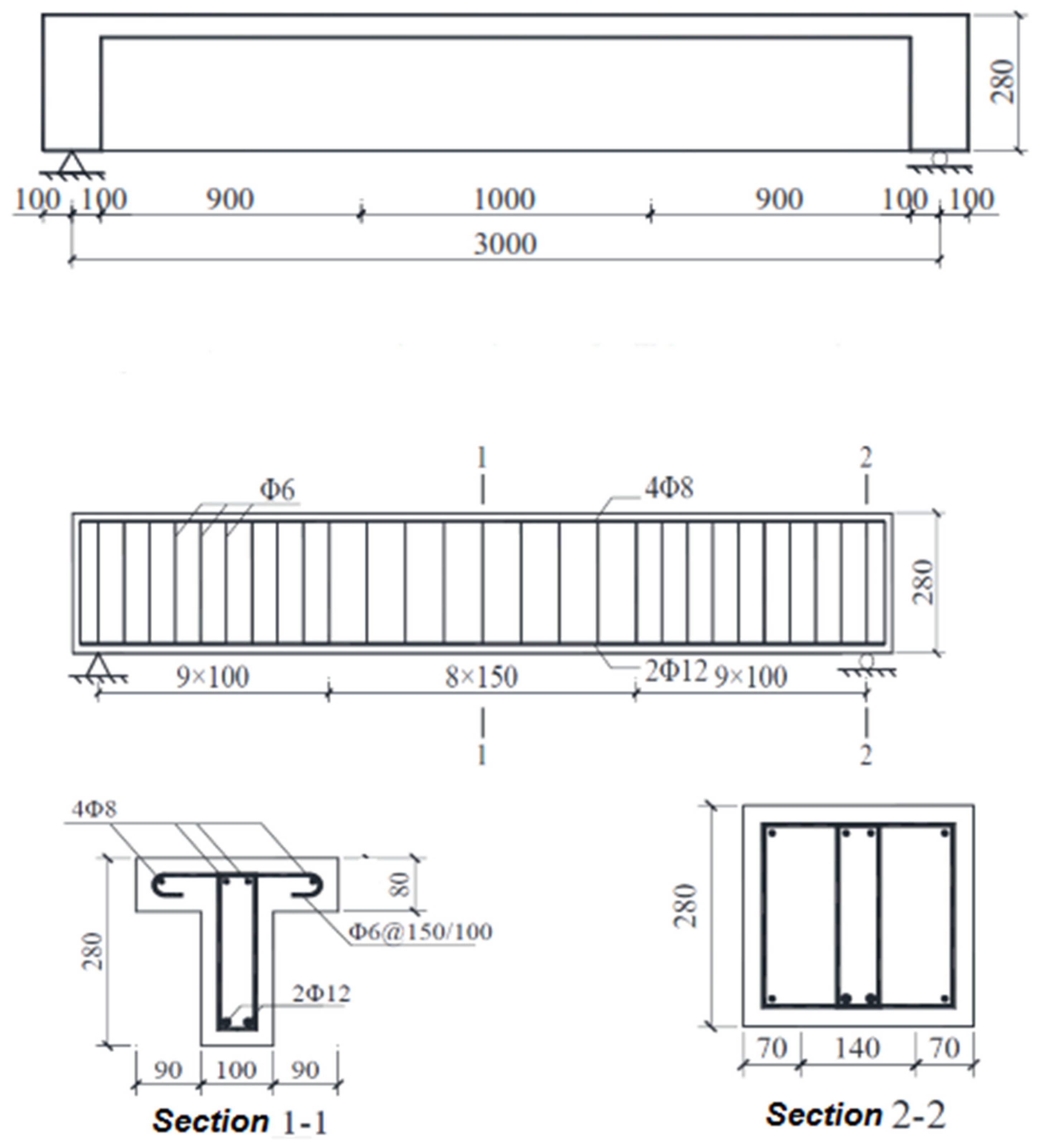
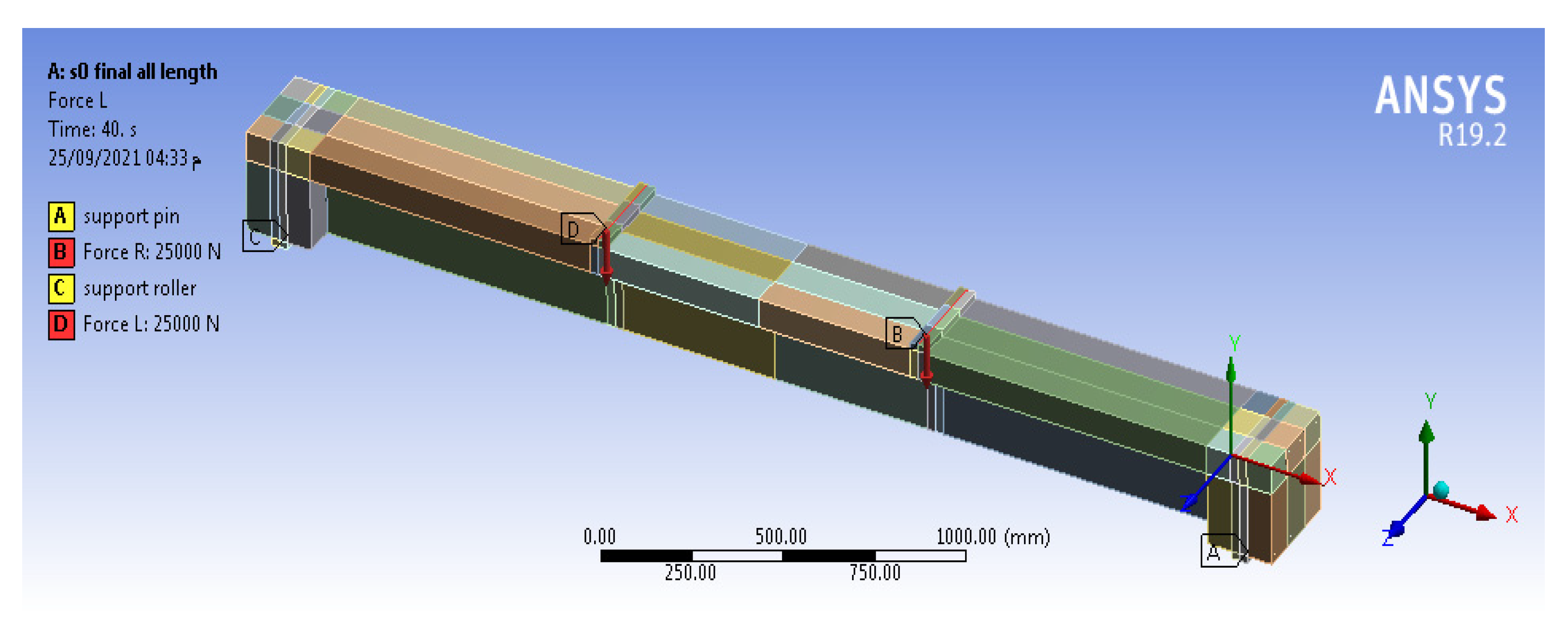
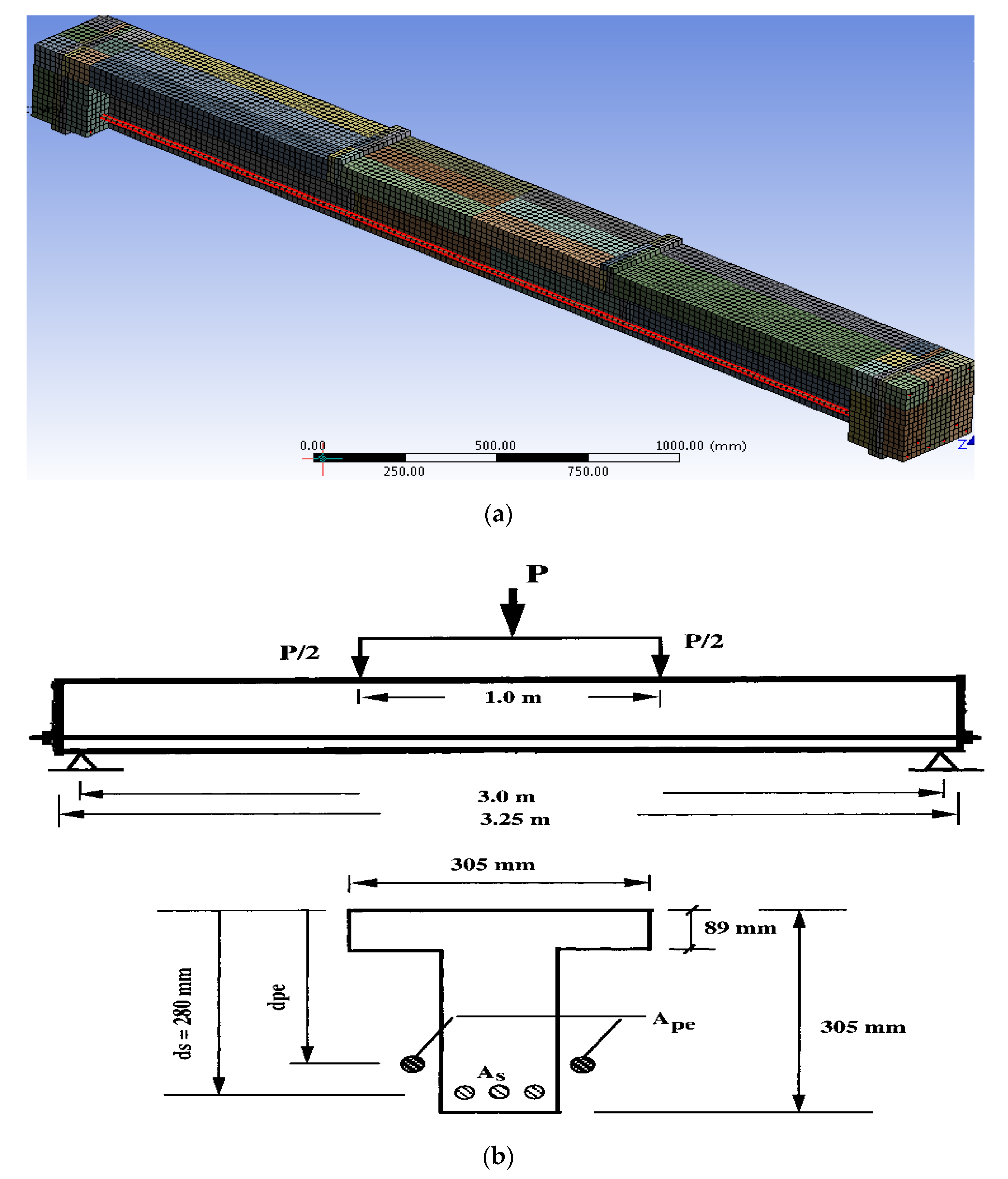
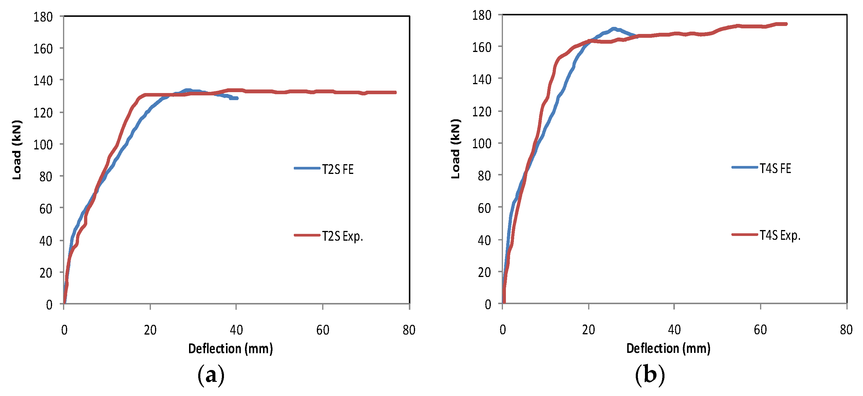
The external tendon profile and the strengthening technique with exterior pre-stressing were changed using deviators. There were three types of tendon profiles based on the number of deviators parameter: straight-line tendons along RC beams (S1 and S2); V-shaped line tendons with one inflection point at the center of the beams (S3 and S4); and U-shaped line tendons with two inflection joints at loading locations (S5 and S6). With respect to the tension method parameter, there were two directions for the tension process, including: the horizontal and tilting tension. The control specimen and the six strengthened specimens are presented in Figure 2.

2.2. Specimen Data

Under vertical loads, six strengthened RC T-beams with outer cables in addition to a control beam without strengthening were tested. Simple supported beams with a 3.2 m outer length and 3.0 m calculated span were used in all tests. The T-beam section’s flange width and height were 280 mm and 80 mm, respectively. The web of the beam section had a width of 100 mm and a height of 200 mm. The geometric features of the testing beams are shown in Figure 3. The internal longitudinal reinforcement in all beams consisted of four 8 mm-diameter rebar reinforcement (8 HRB335) on the top part and two 12 mm-diameter rebar reinforcement (12 HRB335) on the bottom part. To guarantee that flexure failure happened before shear failure, all beams were designed based on the “weak bending capacity and strong shear capacity” principal and according to the Egyptian Code ECP 203 [25]. So, the stirrups were (six HRB335) rebars spaced 100 mm in the shear-bending sections near two supports of the beam (0–1/3L and 2/3L–1L) and 150 mm at the pure bending part (1/3L–2/3L), as presented in Figure 3. The exterior tendons were two post-tensioned steel cables with 9.5 mm-diameter and an 1860 MPa tensile strength. They were arranged symmetrically with regard to the beam web. The concrete was designed to have a strength grade of C40. The Poisson’s ratios for the concrete and steel members were 0.2 and 0.3, respectively, while the Young’s modulus of the concrete and steel members was 37.5 GPa and 200 GPa, respectively, as summarized in Table 1.

2.3. Pre-Stressing and Loading Process

As described in Figure 2, the outer cables were fixed at the specimens according to the profile of every method. Next, a 0.5 fu controlling pre-stress, where fu is the outer tendon’s tensile strength, which equaled 1860 MPa, was applied to all lengths of the tendons. To avoid cracking in the concrete, the concrete strain on the specimen top surface and the wire elongation were recorded simultaneously during tensioning, as illustrated in Figure 4. Then, as indicated in Figure 5, the loading was conducted at two positions in the third of the span.

2.4. Software Program

A nonlinear modeling was conducted by ANSYS WORKBENCH 19.2 FE software for the purpose of the simulation and investigation of the impacts of the strengthening with exterior tendons. Two loading cases were used in the study and modeling. The acting load without post-tensioning force, S0, was one of the loading cases. The additional case was the active load and the post-tensioning force for various cable methods. The post-tensioning force in the wire was computed as a degree of temperature along the cable length (−363.5 °C) to provide a 930 MPa stress for all pre-stressing cables. The concrete was modeled using the 8-node 3D finite element (SOLID 65), the steel and tendon reinforcement was modeled using the beam element (BEAM188, ANSYS Inc.: Canonsburg, PA, USA), and the steel/tendon contact was modeled using the contact element (CONTA175). During the modeling of the cables, the tendon flexural stiffness was neglected, while the tendon axial stiffness was taken into consideration.

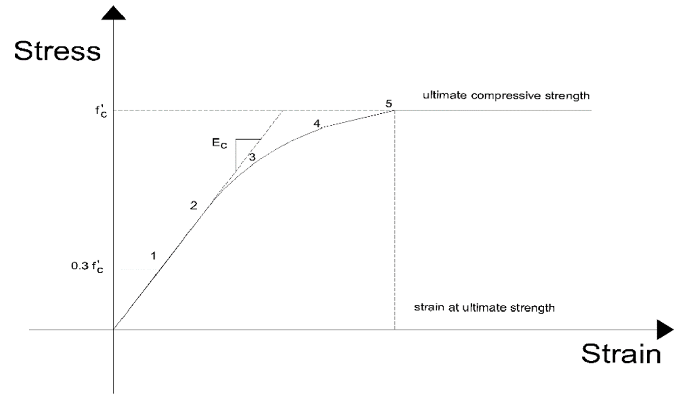
2.4.1. Finite Element Model of Concrete

The three dimensional 8-node element (solid 65 reinforced concrete solids) was used as a model of concrete. The element had eight corner nodes, and each node had three degrees of freedom translation in the (X, Y, Z directions) (ANSYS Manual commands). The concrete was assumed to be homogeneous and initially isotropic. The compressive uniaxial stress–strain relationship for the concrete model was obtained by using the following equations to compute the multi linear isotropic stress–strain curve for the concrete as shown in Figure 6.
f c = ε   E c                       f o r       0 ε ε 1
f c = ε   E c ( 1 + [ ε ε 0 ] 2 )                       f o r       ε 1 ε ε 0
f c = f c                       f o r       ε 0 ε ε c u
ε 0 = 2 f c E c                  
where f c = stress at any strain ε, N/mm2, ε 0 = strain at the ultimate compressive strength, f c , ε c u = ultimate compressive strain, and ε 1 = strain corresponding to (0.3   f c ).
The multi linear isotropic stress–strain implemented requires the first point of the curve to be defined by the user. It must satisfy Hooke’s law. The multi linear curves were used to help with the convergence of the nonlinear solution algorithm. The crack modeling depended on smeared cracking modeling [19,20].

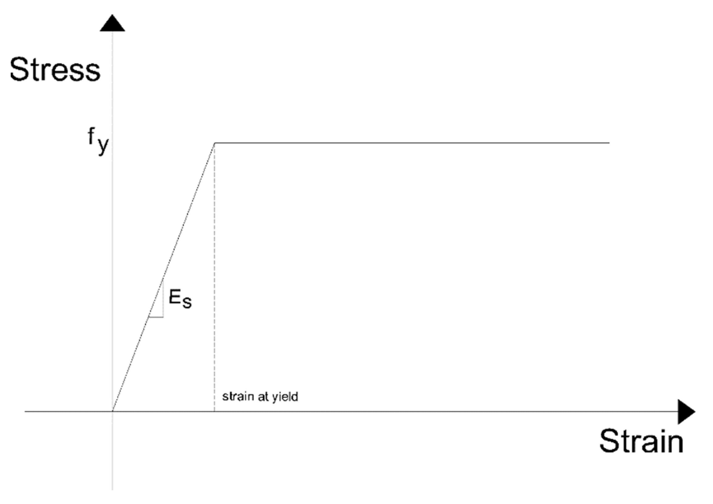
2.4.2. Finite Element Model of Steel Bars

In this study, the ANSYS WORKBENCH library is used to model the steel reinforcement by using the (beam element BEAM188). The stress–strain relationship for ordinary reinforcing steel is a bilinear relationship assumed to be elastic—perfectly plastic, as shown in Figure 7.

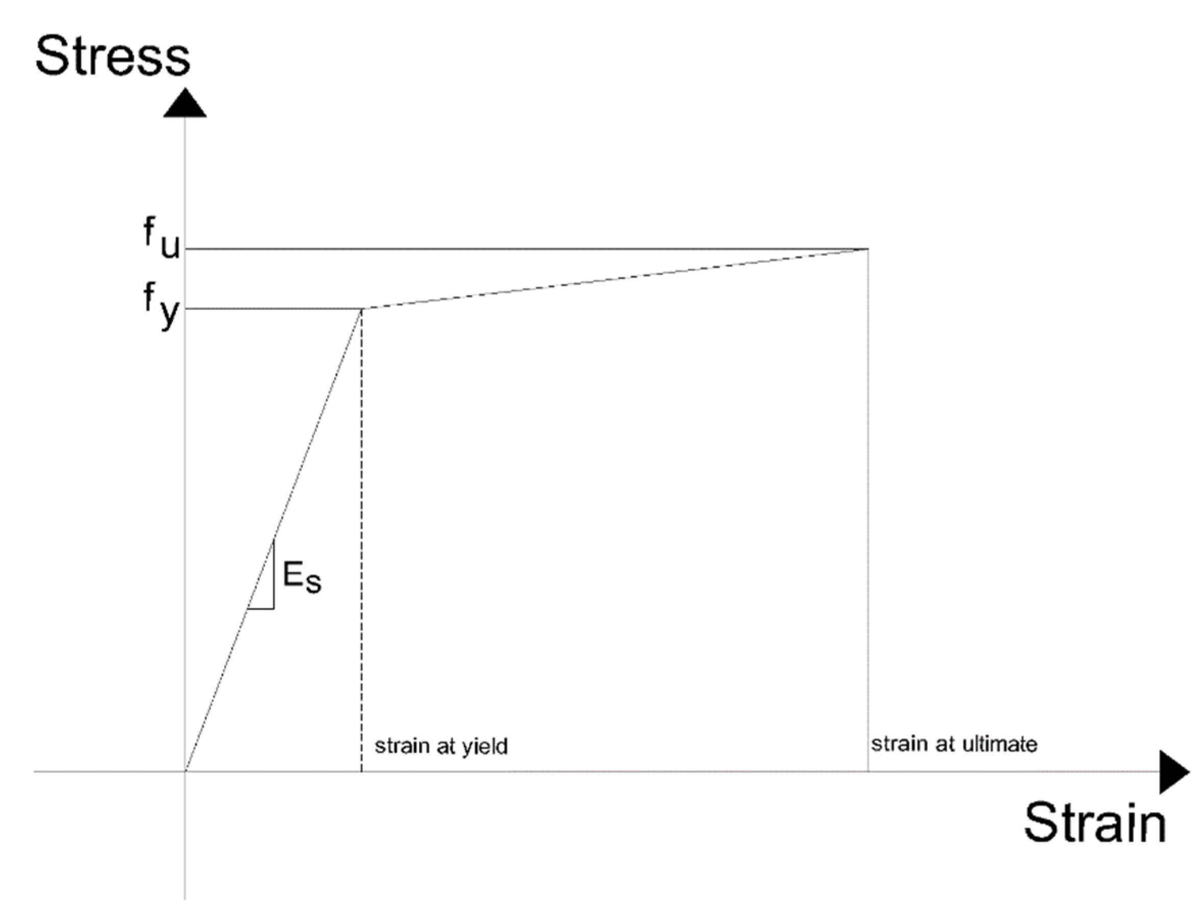
2.4.3. Finite Element Model of External Tendon

For pre-stressing tendons, a bilinear elastic–plastic with hardening provides the relationship of stress–strain, as shown in Figure 8. The modulus of the strain-hardening portion is assumed to be (2%) of the modulus of elasticity of steel.

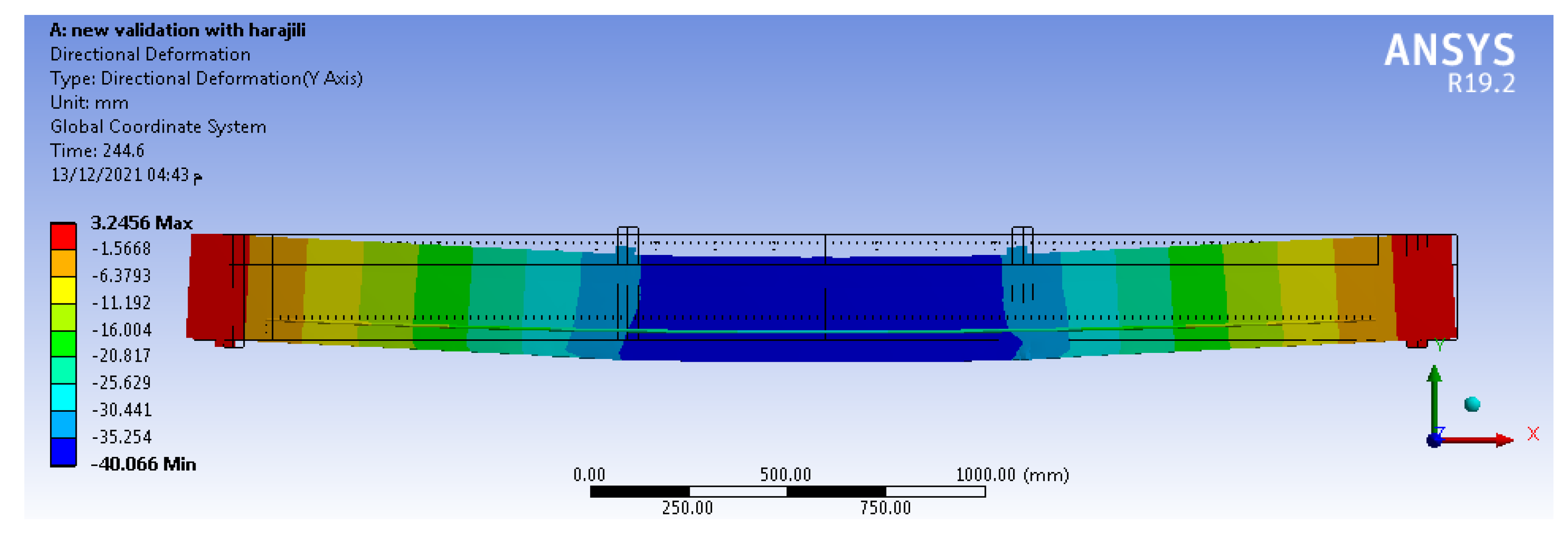
3. Validation of the Models

The finite element models that were used in this investigation were validated by field tests of existing specimens, which were enhanced by Harajli M. et al. [26] using post-tensioning methods. Laboratory testing for beams was simulated via ANSYS WORKBENCH 19.2 under similar conditions. Over a 3.0 m span, Harajli M. et al. [26] studied twelve specimens of T-sectioned simple beam, as described in Figure 9. The samples were separated into four groups, with two external post-tensioned beams and one without strengthening in each group. For analysis and verification, T2S and T4S, two externally pre-stressed RC beams, were chosen. Beam T2S belonged to group two, whereas beam T4S belonged to the fourth group. In beams T2S and T4S, there was no deviator. The T4S and T2S beams had tendons with straight-line shapes and 84 mm eccentricities throughout the whole beam length. Table 2 shows the material parameters’ summary of the chosen beams, including: the area of steel bars As, yield stress of steel bars fy, area of the external pre-stressing tendon Apc, stress of the initial pre-tensioning of tendons fpe, ultimate tensile strength of tendons fpu, and the concrete cylindrical compressive strength f′c.
Figure 10 shows the differences between the experimental measurements and the analytical predictions for the complete load–midspan deflection response of the beam specimens. Figure 10 displays how the FE models reproduce the laboratory load–displacement relation from zero to ultimate load. It is also worth noting that these curves reflect information about three different loading phases during the operation. The transition to the second stage from the first stage was caused by concrete cracking, whereas reinforcing steel yielding led to a shift in the load–deflection curve to the third stage from the second stage. Figure 11 shows the third stage of failure, which included the maximum mid-span deflection.

4. Strengthening Beams Using External Tendons
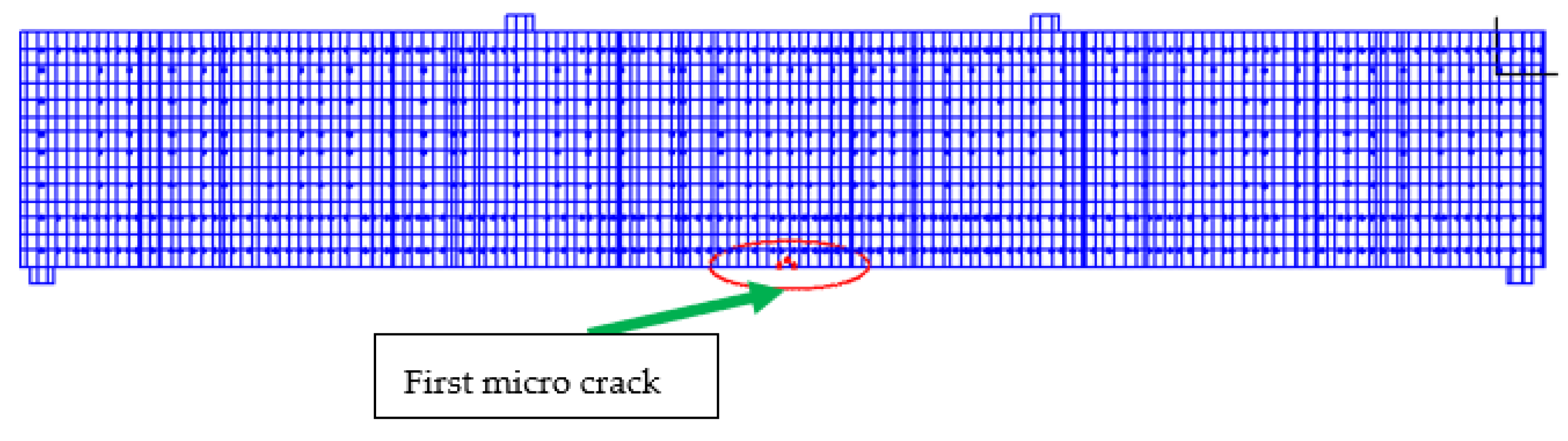
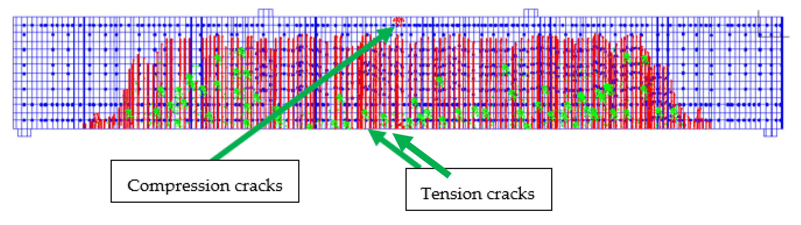
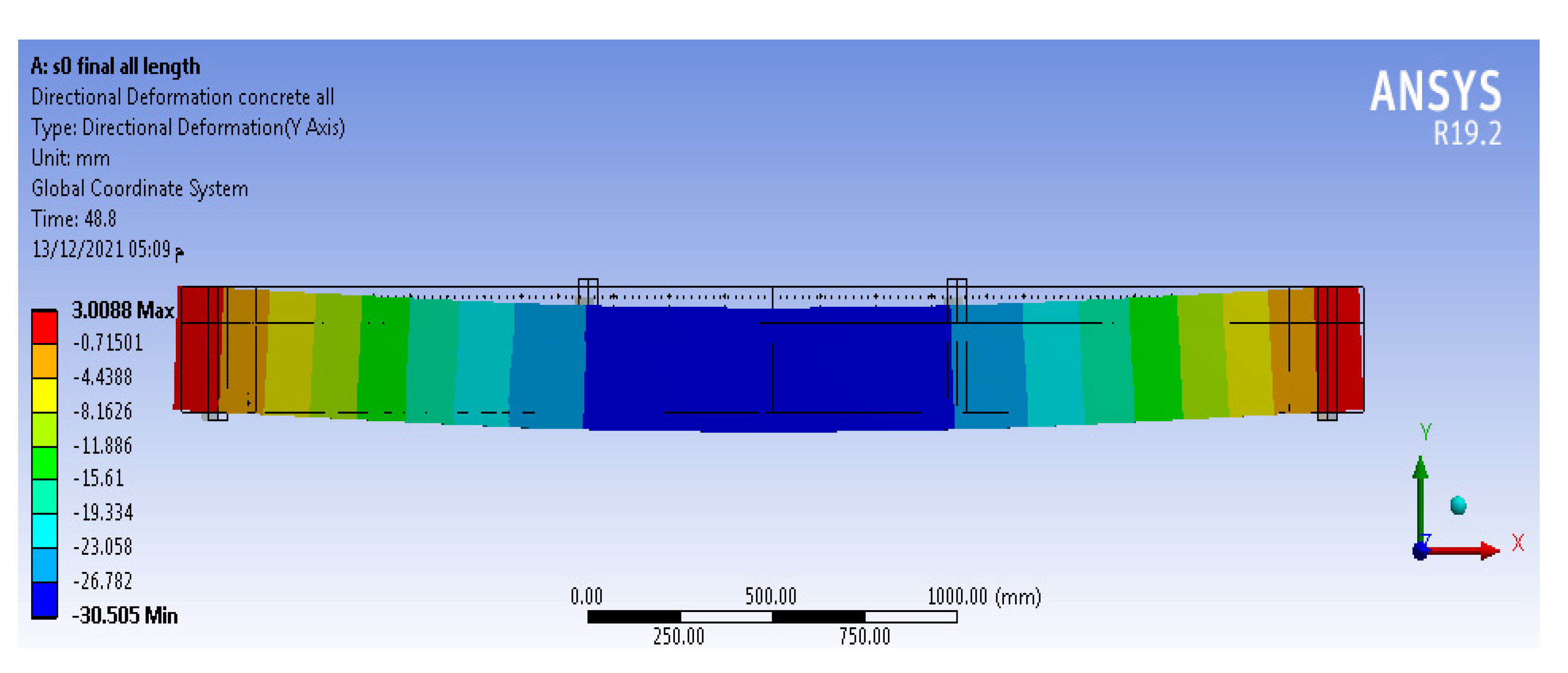
4.1. Failure Modes

Under the same loading conditions, the failure phases of the original unstrengthened specimen (S0) in addition to the six strengthened specimens (S1, S2, S3, S4, S5, and S6) were nearly identical. As a result, only the failure stages of specimen S0 are described here.
The initial micro crack appeared at the mid-third section of specimen S0 on the bottom beam surface at a 16 kN applied load and a deflection of 0.65 mm. As indicated in Figure 12, the force was classified as a cracking load at this time. While the loading increased, the specimen’s deflection and concrete strain increased at the same time; the size and number of the cracks in the middle third section additionally increased. Furthermore, the region of cracking shifted to the shear-bending area (two edge thirds) from the pure bending area (middle third). When the loading value and maximum deflection of the specimen S0 were 23 kN and 3.42 mm, respectively, the tensile bar reinforcement stress achieved its yield strength. The load was then denoted as yield load. Steel rebars could no longer support the applied loads after this point (yield point), and strains on the specimen grew rapidly, resulting in a rise in the cracks’ length and breadth within a short time period. Lastly, at a 139.26 kN applied load and a maximum deflection of 30.41 mm, the cracks extended from the tension zones to the compressive zones, and the specimen collapsed as a typical flexural failure with a high vertical displacement, as illustrated in Figure 13 and Figure 14. The force was recorded as the maximum load at this moment (load carrying capacity).
In general, the failure mechanisms of six externally pre-stressed strengthened specimens matched those of the original specimen (S0). The flexural response of the seven specimens under the identical loading procedure was passed through the following steps: micro-bending crack appearance (cracking stage); tensile rebar yield and fast vertical displacement (yielding stage); then failure of the specimens resulting in high bending deformations (ultimate stage). Because of the positive influence of the outer post-tensioning cables, the cracking, yielding, and ultimate load values of the six strengthened specimens were higher than those for the unstrengthened specimen (S0). Table 3 summarizes the theoretical test (FE) outcomes of the cracking, yielding, and ultimate phases, such as the maximum deflection at the mid-span and the applied load.

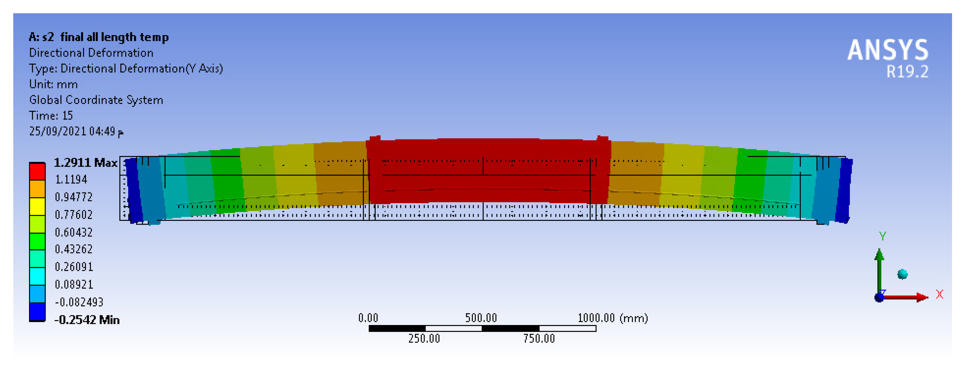
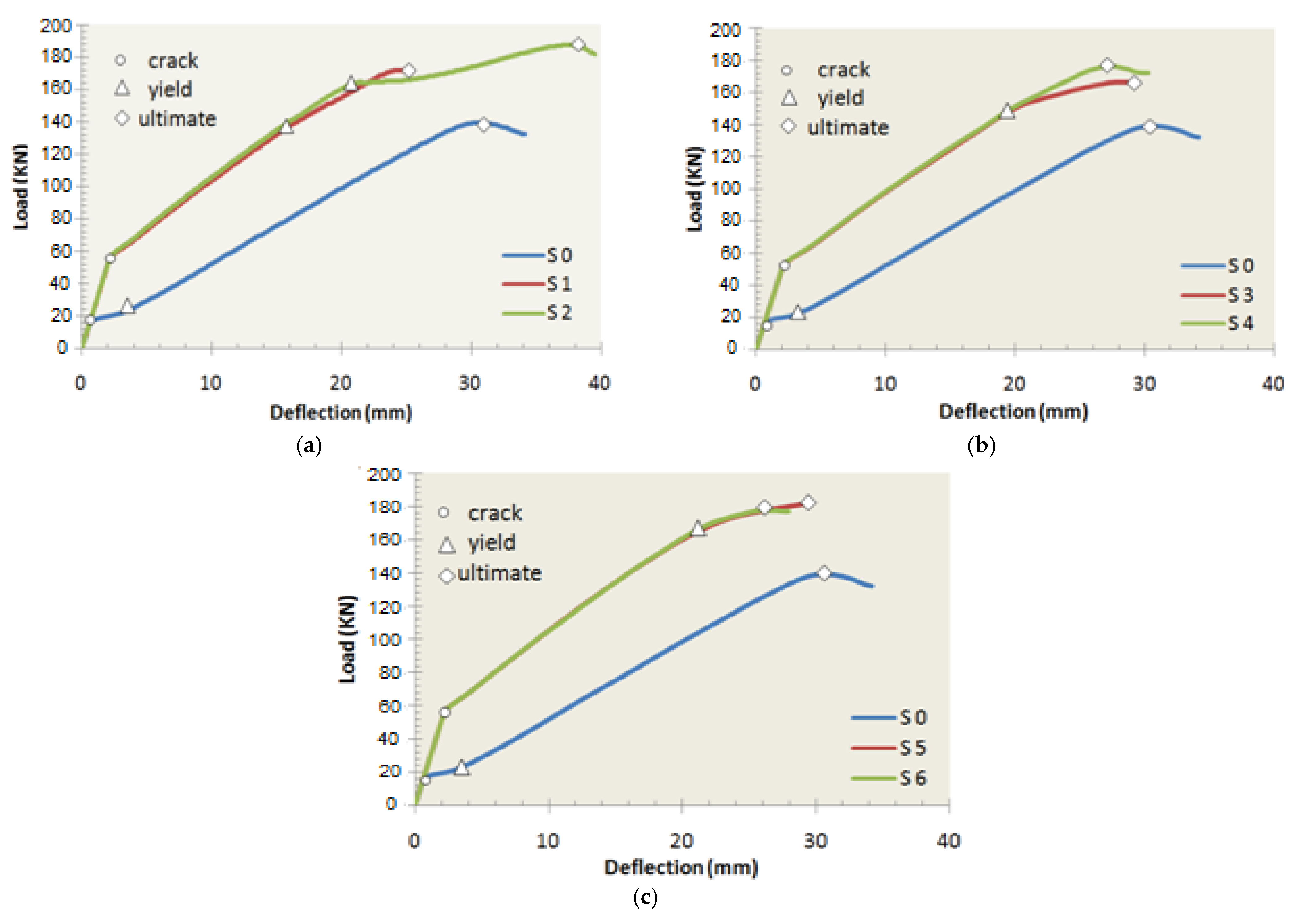
4.2. Load–Deflection Curves

Figure 15 displays the relationship between loading and maximum deflection for the seven FE test specimens. The figure illustrates that the six externally enhanced specimens followed the same mechanical behavior prior to cracking until the deflection and load values reached approximately 1.25 mm and 56 kN, respectively. The deflection of the unstrengthened specimen S0 increased quickly after first cracks and tensile rebars approached the yield. Next, the beam collapsed with significant ductility. The tendons’ ability to sustain some of the increased tensile stress caused by vertical loading allowed the remainders of the strengthened specimens to withstand loading better than S0 and delayed the tensile steel reinforcements’ yielding. This enabled the load–deflection curves to climb.
Figure 15a compares the results of specimen S1 and specimen S2 to show the influence of the tendon profile variable (mid-deviators) on the load–deflection curve. The load–displacement relation for S1 and S2 were similar when the force was less than the yield load, but when acting forces were raised, a gap appeared between the load–displacement relations of S1 and S2. This was due to the fact that when applied forces were less than the yield force, the specimen’s vertical displacement was very small. As a result, in specimen S2, the external strengthening tendons and the surrounding deviators were detached. When the acting forces exceeded the yield zone, the specimen’s vertical displacement increased quickly, resulting in the exterior tendons bonding to the surrounding deviators. As a result, the effects of the deviators in specimen S2 began to clarify and enhance its structural response. As a result, the failure force of specimen S2 was 187.46 kN, which was 9.1 percent greater than the ultimate load of specimen S1. Generally, deviators had a good impact on the load capacities of enhanced specimens, and this result appeared also when a comparison was performed between specimen S3 (one deviator) and specimen S5 (two deviators). The ultimate load of specimen S5 (two deviators) was recorded at 181.20 kN, which increased by 8.6% compared to specimen S3 (one deviator), which was recorded at 166.90 kN. Finally, deviators play an important role in external strengthening pre-stressing techniques. Thus, at least one middle-deviator of a straight-line tendon is preferred for strengthening simple T-beams.
Figure 15 also shows the tension method parameter effects on the load–displacement relation by comparing the results for specimen S3 versus specimen S4 in Figure 15b and specimen S5 with specimen S6 in Figure 15c. It could be noticed that the differences between the load–displacement relations of S3 and S4 or S5 and S6 were very small, which indicates that the tension direction of the external tendon has little impact on the mechanical behavior of enhanced specimens. Therefore, a horizontal or tilting direction of the tendon tensioning process can be used.

4.3. Load-Carrying Capacity

All strengthened specimens’ cracking, yielding, and ultimate loads are listed in Table 4, as well as the percentage of improvement over the unstrengthened specimen (S0) and the strengthened specimen without any mid-deviators (S1). Table 4 shows that the strengthening methods using outer post-tensioning cables may successfully improve the cracking, yielding, and ultimate forces of all the specimens by various percentages. The yielding and cracking loads of all the strengthened beams increased by a larger percentage than the failure forces due to the outer post-tensioning cables, which might postpone the yield of tensile rebars and bear the majority of the tensile stress. This means that strengthening with an external tendon improves the mechanical behavior during the yielding and cracking stages better than at the ultimate stage for simple beam cases. From all the specimens, the specimen that was enhanced with straight-line tendon and two deviators (specimen S2) recorded the highest load capacity, while the specimen that was enhanced with a V-shape tendon and one deviator (specimen S3) recorded the minimum load capacity. It can also be observed that specimens that were strengthened with U-shape tendon (i.e., sample S5) had a light priority in structural loading carrying compared to specimens that were strengthened with V-shape tendons (i.e., sample S3). Because these specimens are simple beams, most of their sections along the beam span are exposed to one type of stress, but if the specimens had opposite stresses along the span (i.e., frame sample), the beneficial effects of the U-shape tendons and V-shape tendons would appear more than the straight-line tendons on the load capacity. Generally, specimen S2 (strengthening with straight-line tendons and two deviators) represents the ideal technique of strengthening with external tendons for previous specimens (simple beams).

4.4. Ductility Analysis

The mechanical property of linear elasticity may be obviously shown from the testing of the external strengthening beams and the load–displacement relation. Although the elasticity of these models was significant, the ductility was low due to the quick collapse after yielding. The structure’s ductility is typically estimated using the coefficient of ductility μ that is represented by:
μ = Δ u Δ y
where Δ y is the vertical displacement or deflection of the specimen that is measured when tensile steel bars achieve their yield stress, and Δ u is the displacement or deflection that is measured when the applied force reaches the structure’s ultimate load (at the mid-span in the simple beam case). Table 5 shows the displacement ductility coefficients of the specimens under study. The external strengthened beams were significantly lower ductile than the original beam, as can be seen in Table 5. The ductility of strengthened specimens decreased from 80% to 86% compared to the unstrengthened specimen S0. It can further be noticed that the number of deviators had a light effect on the coefficient of ductility. The strengthened beam S2 had an 80% reduction in ductility, while the strengthened beam S1 had an 84% reduction in ductility. Furthermore, the tension method of external tendons had nearly no effect on the coefficient of the ductility (as shown in cases S3, S4, S5, and S6), which decreased by approximately 85% compared to the unstrengthened specimen.

5. Conclusions

The main conclusions were obtained from the finite element research that was conducted on simple beams strengthened using exterior pre-stressed methods:
The FE results are largely consistent with the laboratory experiments performed by Harajli et al.
The results indicate that strengthening the RC beams using external pre-stressing cables enhances their ultimate load-carrying capacity and mechanical behavior substantially.
Strengthening beams with external pre-stressing techniques can delay the early cracking load by approximately 228–275% when compared to an unstrengthened beam.
Strengthening beams with external pre-stressing techniques can improve the load-carrying capacity by 522–639% for yield and 24–35% for ultimate capacity compared to an unstrengthened beam.
The number of interior deviators and the profile of tendon have a significant impact on the load-capacity, but only a little impact on the ductility. Beams that were strengthened with two deviators (straight-line tendons as in S2 and U-shaped tendons as in S5) increase the load-carrying capacity by about 9.1 and 8.6%, respectively, compared to the strengthened beams without deviators (straight-line tendons as in S1), and with one deviator (V-shape tendons as in S3). In addition, the strengthened beam with a straight-line tendon and two deviators, S2, features the highest ductility factor. Therefore, the idea of external pre-stressing straight-line tendons and two inner deviators is recommended for strengthening simple T-beam cases.
Although, strengthening an existing T-beam using an external tendon with mid-deviators has some field-application difficulties, the results show that using at least one mid-deviator is required to achieve a good level of improvement in the structural performance.
The tension method of the external tendon exerts a light impact on the loading capacity and the ductility of the specimens. Therefore, the tilting tension method or the horizontal tension method can be used. So, the horizontal tension method is recommended for simple implementation in the field.
On the basis of the experimental study and the detailed FE analysis, more research is needed to create a practical technique for indeterminate structure enhancing using exterior pre-stressed methods in addition to performing parametric study for more parameters including the span/depth ratio, pre-stressing force, and strength of concrete.

Author Contributions

Visualization, supervision, writing—review and editing, G.A.M.; validation, formal analysis, writing—original draft preparation, A.S.E.; resources, software, M.H.E.-F.; writing—review and editing, investigation, P.P. and R.R. All authors have read and agreed to the published version of the manuscript.

Funding

This work was supported by the Slovak Research and Development Agency under the contract no. APVV-17-0549. This work was supported by the Slovak Research and Development Agency under the contract no. APVV-20-0281.

Institutional Review Board Statement

Not applicable.

Informed Consent Statement

Not applicable.

Data Availability Statement

Not applicable.

Conflicts of Interest

The authors declare no conflict of interest.

References

  1. Zou, J.; Huang, Y.; Feng, W.; Chen, Y.; Yue, H. Experimental study on flexural behavior of concrete T-beams strengthened with externally prestressed tendons. Math. Biosci. Eng. 2019, 16, 6962–6974. [Google Scholar] [CrossRef] [PubMed]
  2. Lee, S.-H.; Shin, K.-J.; Lee, H.-D. Post-Tensioning Steel Rod System for Flexural Strengthening in Damaged Reinforced Concrete (RC) Beams. Appl. Sci. 2018, 8, 1763. [Google Scholar] [CrossRef] [Green Version]
  3. Xin, Y.; Wu, J.; Wu, Q.; Cui, W.; Zhang, S.; Cheng, S. Study on the sickle anchoring joint in external prestressing strengthening of portal frame. Structures 2020, 28, 552–561. [Google Scholar] [CrossRef]
  4. Tan, K.-H.; Ng, C.-K. Effects of Deviators and Tendon Configuration on Behavior of Externally Prestressed Beams. ACI Struct. J. 1997, 94, 13–22. [Google Scholar] [CrossRef]
  5. Fan, Y.L. Collapse Behavior of RC Column-Beam Sub-Structure with External Prestressing Tendons. Appl. Mech. Mater. 2016, 847, 325–330. [Google Scholar] [CrossRef]
  6. Aslam, M.; Shafigh, P.; Jumaat, M.Z.; Shah, S.N.R. Strengthening of RC beams using prestressed fiber reinforced polymers–A review. Constr. Build. Mater. 2015, 82, 235–256. [Google Scholar] [CrossRef]
  7. Liu, T.; Xiao, Y.; Yang, J.; Chen, B.S. CFRP Strip Cable Retrofit of RC Frame for Collapse Resistance. J. Compos. Constr. 2017, 21, 04016067. [Google Scholar] [CrossRef]
  8. Mukherjee, A.; Rai, G. Performance of reinforced concrete beams externally prestressed with fiber composites. Constr. Build. Mater. 2009, 23, 822–828. [Google Scholar] [CrossRef]
  9. Nordin, H. Strengthening Structures with Externally Pre-Stressed Tendons: Laboratory Tests; University of Technology, Technical Report, Department of Civil and Environmental Engineering, Division of Structural Engineering, Luleå University of Technology: Lulea, Sweden, 2005; Available online: https://dokumen.tips/documents/strengthening-structures-with-externally-prestressed-tendons-997963fulltext01pdf.html?page=1 (accessed on 20 April 2022).
  10. Nordin, H. Strengthening Structures with Externally Pre-Stressed Tendons: Literature Review; University of Technology, Technical Report, Department of Civil and Environmental Engineering, Division of Structural Engineering, Luleå University of Technology: Lulea, Sweden, 2005; Available online: http://citeseerx.ist.psu.edu/viewdoc/download?doi=10.1.1.620.5475&rep=rep1&type=pdf (accessed on 20 April 2022).
  11. Stoll, F.; Saliba, J.E.; Casper, L.E. Experimental study of CFRP-prestressed high-strength concrete bridge beams. Compos. Struct. 2000, 49, 191–200. [Google Scholar] [CrossRef]
  12. Picard, A.; Massicotte, B.; Bastien, J. Relative efficiency of external prestressing. J. Struct. Eng. 1995, 121, 1832–1841. [Google Scholar] [CrossRef]
  13. Ghallab, A.; Beeby, A.W. Calculating stress of external prestressing tendons. Struct. Build. 2004, 157, 263–278. [Google Scholar] [CrossRef]
  14. Kim, J.; Shin, W.-S. Retrofit of RC frames against progressive collapse using prestressing tendons. Struct. Design Tall Spec. Build. 2013, 22, 349–361. [Google Scholar] [CrossRef]
  15. Mahmoud, N.S.; Badr, A.; Ssalem, F.A.; Ghannam, M. Strengthening Steel Frames by Using Post Tensioned Cable. Life Sci. J. 2014, 11, 111–116. Available online: https://www.researchgate.net/publication/289610723_Strengthing_steel_frames_by_using_post_tensioned_cable (accessed on 20 April 2022).
  16. Ghannam, M.; Mahmoud, N.S.; Badr, A.; Salem, F.A. Effect of post tensioning on strengthening different types of steel frames. J. King Saud Univ.–Eng. Sci. 2017, 29, 329–338. [Google Scholar] [CrossRef] [Green Version]
  17. Diep, B.K.; Umehara, H. Non-linear Analysis of Externally Prestressed Concrete Beams. Electron. J. Struct. Eng. 2002, 2, 85–96. Available online: https://citeseerx.ist.psu.edu/viewdoc/download?doi=10.1.1.1083.8062&rep=rep1&type=pdf (accessed on 20 April 2022).
  18. Harajli, M.H. Strengthening of Concrete Beams by External Prestressing. PCI J. 1993, 38, 76–88. Available online: https://www.pci.org/PCI_Docs/Publications/PCI%20Journal/1993/November/Strengthening%20of%20Concrete%20Beams%20by%20External%20Prestressing.pdf (accessed on 20 April 2022). [CrossRef]
  19. Lou, T.-J.; Xiang, Y.-Q. Finite element modeling of concrete beams prestressed with external tendons. Eng. Struct. 2006, 28, 1919–1926. [Google Scholar] [CrossRef]
  20. Ibrahim, A.M. Parametric Study of Continuous Concrete Beam Prestressed with External Tendon. Jordan J. Civ. Eng. 2010, 4, 11. [Google Scholar]
  21. Lou, T.; Lopes, S.M.R.; Lopes, A.V. Flexural Response of Continuous Concrete Beams Prestressed with External Tendons. J. Bridge Eng. 2013, 18, 525–537. [Google Scholar] [CrossRef]
  22. Kobrosli, H.; Baalbaki, O.; Jahami, A.; Abou Saleh, Z.; Khatib, J.; Kırgız, M.; Galdino, A. Influence of various design parameters of the grouted duct on mono-strand bond behavior in post-tensioned members. J. Mater. Res. Technol. 2022, 17, 1232–1245. [Google Scholar] [CrossRef]
  23. Kobrosli, H.; Baalbaki, O.; Jahami, A.; Saleh, Z.; Khatib, J.; Sonebi, M. Effect of duct type, size, and embedment on bond behavior of post-tensioned mono-strand concrete members. Mater. Today Proc. 2022, 58, 1205–1210. [Google Scholar] [CrossRef]
  24. ANSYS Workbench. Computer Software for Finite Element Analysis; Verification Manual, Release 19.2; ANSYS Inc.: Canonsburg, PA, USA, 2018. [Google Scholar]
  25. Housing and Building National Research Centre. Egyptian Code of Practice, code no. ECP 203, 2007. In Ministry of Housing, Utilities and Urban Communities, 1st ed.; Housing and Building National Research Centre: Cairo, Egypt, 2007. [Google Scholar]
  26. Harajli, M.; Khairallah, N.; Nassif, H. Externally Prestressed Members: Evaluation of Second-Order Effects. J. Struct. Eng. ASCE 1999, 125, 1151–1161. Available online: https://ascelibrary.org/doi/abs/10.1061/(ASCE)0733-9445(1999)125:10(1151) (accessed on 20 April 2022).
Figure 1. Layout of an externally post-tensioned box girder bridge.
Buildings 12 00789 g001
Figure 2. Several techniques for the external pre-stressing of simple beams.
Buildings 12 00789 g002
Figure 3. Specimen data.
Buildings 12 00789 g003
Figure 4. Pre−stressing process of specimen S2.
Buildings 12 00789 g004
Figure 5. The FE applied loads for specimens.
Buildings 12 00789 g005
Figure 6. Simplified compressive Uniaxial stress-strain curve for concrete (Adapted from Refs. [19,20]).
Buildings 12 00789 g006
Figure 7. Constitutive law for steel reinforcement (Adapted from Refs. [19,20]).
Buildings 12 00789 g007
Figure 8. Constitutive law for the external tendon (Adapted from Refs. [19,20]).
Buildings 12 00789 g008
Figure 9. Loading method and external tendon profile: (a) FE; (b) experimental (Adapted from Ref. [26]).
Buildings 12 00789 g009
Figure 10. Load–displacement relation for laboratory tests (Adapted from Ref. [26]). versus FE tests: (a) Beam T2S; (b) Beam T4S.
Buildings 12 00789 g010
Figure 11. Vertical deflection at failure of specimen T2S.
Buildings 12 00789 g011
Figure 12. First cracks of specimen S0.
Buildings 12 00789 g012
Figure 13. Cracks at failure of specimenS0.
Buildings 12 00789 g013
Figure 14. Vertical deflection at the failure of specimen S0.
Buildings 12 00789 g014
Figure 15. Load–displacement relation of all specimens: (a) straight-line tendons (S0 with S1 and S2); (b) V-shaped tendons (S0 with S3 and S4); (c) U-shaped tendons (S0 with S5 and S6).
Buildings 12 00789 g015
Table 1. Properties of all tested beam specimens.
PropertiesConcreteSteelTendon
f′c (MPa)Ec (GPa)Poisson’s Ratiofy (MPa)Es (GPa)Poisson’s Ratiofpu (MPa)Es (GPa)Poisson’s Ratio
value4037.50.23352000.318602000.3
Table 2. Properties of the chosen beam specimens [26].
Beam SpecimenAs (mm2)
Steel
Steel
fy (MPa)
Tendon
Ape (mm2)
Tendon
fpe (MPa)
Tendon
fpu (MPa)
Concrete
f′c (MPa)
T2S340.0612.039.0935.01607.040.1
T4S603.0413.775.0994.01986.041.8
Table 3. FE results of beam specimens.
Specimen No.CrackingYieldingUltimate
Load kNMaximum
Deflection mm
Load
kN
Maximum
Deflection mm
Load
kN
Maximum
Deflection mm
S0160.6523.003.42139.2630.41
S1560.95143.1216.06171.7623.04
S2601.37164.3420.28187.4636.16
S3531.10153.5019.79166.9027.11
S4521.13155.3819.91176.7826.27
S5561.05170.0221.54181.2028.41
S6581.19168.1220.53177.3824.93
Table 4. Load–carrying capacity results of all beams.
Specimen No.CrackingYieldingUltimate
Load kN% Increase over S0% Increase over S1Load kN% Increase over S0% Increase over S1Load kN% Increase over S0% Increase over S1
S016--23.00--139.26--
S156250-143.12522-171.7624.0-
S2602757.15164.3461414.83187.4635.09.14
S353231−5.36153.505677.25166.9020.0−2.83
S452228−7.15155.385758.57176.7827.02.92
S5562500.00170.0263918.80181.2030.05.50
S6582623.57168.1263117.47177.3827.53.27
Table 5. Ductility analysis of all beams.
Specimen No.Tendon Profile Δ y
mm
Δ u
mm
μ = Δ u Δ y % Decrease
S0-3.4230.418.9-
S1straight16.0623.041.484
S2straight20.2836.161.880
S3V-shape19.7927.111.484
S4V-shape19.9126.271.385
S5U-shape21.5428.411.385
S6U-shape20.5324.931.286
Publisher’s Note: MDPI stays neutral with regard to jurisdictional claims in published maps and institutional affiliations.

