Article

Cost Factor Analysis for Timber–Concrete Composite with a Lightweight Plywood Rib Floor Panel

by
Karina Buka-Vaivade
*,
Dmitrijs Serdjuks
and
Leonids Pakrastins
Institute of Structural Engineering, Riga Technical University, LV-1048 Riga, Latvia
*
Author to whom correspondence should be addressed.
Buildings 2022, 12(6), 761; https://doi.org/10.3390/buildings12060761
Submission received: 28 April 2022 / Revised: 24 May 2022 / Accepted: 31 May 2022 / Published: 3 June 2022

Abstract

:
With the growing importance of the principle of sustainability, there is an increasing interest in the use of timber–concrete composite for floors, especially for medium and large span buildings. Timber–concrete composite combines the better properties of both materials and reduces their disadvantages. The most common choice is to use a cross-laminated timber panel as a base for a timber–concrete composite. But a timber–concrete composite solution with plywood rib panels with an adhesive connection between the timber base and fibre reinforced concrete layer is offered as the more cost-effective constructive solution. An algorithm for determining the rational parameters of the panel cross-section has been developed. The software was written based on the proposed algorithm to compare timber–concrete composite panels with cross-laminated timber and plywood rib panel bases. The developed algorithm includes recommendations of forthcoming Eurocode 5 for timber–concrete composite design and an innovative approach to vibration calculations. The obtained data conclude that the proposed structural solution has up to 73% lower cost and up to 71% smaller self-weight. Thus, the proposed timber–concrete composite construction can meet the needs of society for cost-effective and sustainable innovative floor solutions.

1. Introduction

A natural renewable resource, timber, as a construction material, has a lower environmental impact [1,2] and combines high flexural strength with low weight, which is a significant advantage over other construction materials. However, the use of timber floors at medium and large spans is associated with human discomfort due to the high sensitivity of the floor to vibrations [3,4,5,6]. The combination of timber with concrete, which is a stiffer material with high compressive strength, increases the overall stiffness of the structure [7]. Compared with classic reinforced concrete floors, timber–concrete composite (TCC) floors significantly reduce the self-weight of floor structures and thus the dimensions of other vertical structures and foundations [8]. According to existing studies [9], with the increase in the span of the floor structure up to six meters, the required floor thickness of the TCC and reinforced concrete structures is almost the same, but the self-weight load caused by the TCC structure is more than half that of the reinforced concrete structure. Thus, it can be concluded that the TCC floor is an effective alternative to the classic floor solutions made of reinforced concrete [9,10]. The topicality of TCC is further confirmed by the current development of prCEN/TS Eurocode 5: Design of Timber Structures—Structural design of timber–concrete composite structures—Common rules and rules for buildings [11].
The most significant effect of combining two materials—timber and concrete for use in non-seismic zones, can be obtained by providing a rigid connection between these layers. In this way, full composite action is ensured, and both layers work as one element with one neutral axis [12]. Given that the serviceability limit state (SLS) for structures subjected to the flexure is usually decisive [13,14], the full performance of the composite is of particular importance. Full action of the composite leads to smaller deflections of the element [15] and can ensure the concrete action only in the compressed area [16]. An adhesive connection can provide a rigid connection between the concrete and timber layers. Currently, two technologies for developing glued connections are known—dry and wet. The dry method is characterised by difficulties in quality control of the glued connection. In the case of the wet method, there is a risk of glue shifting during the placement of fresh concrete [
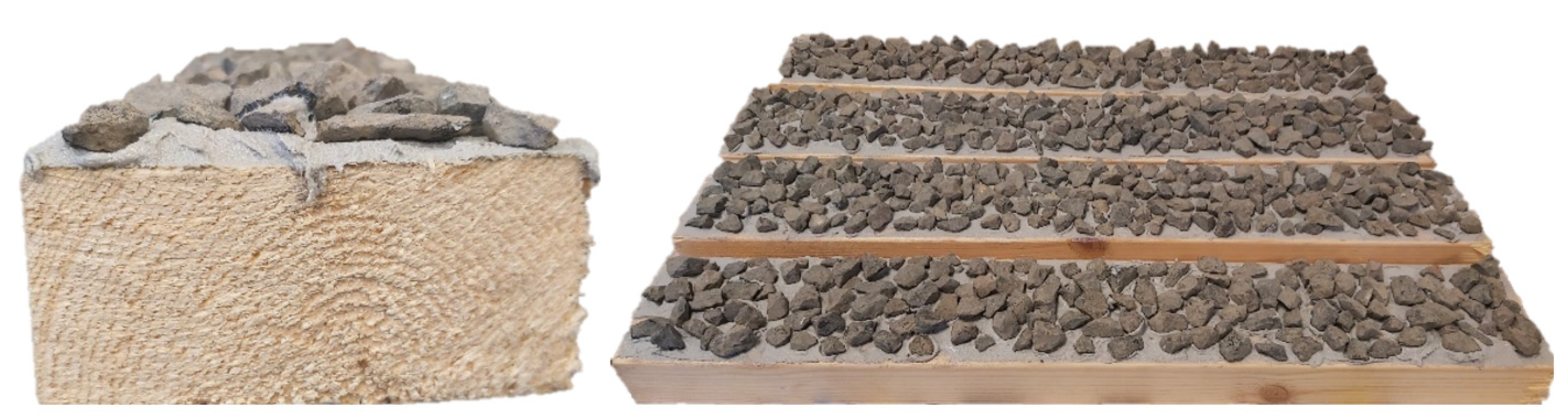
10]. As part of developing a more rational timber–concrete composite solution, an innovative technology producing a rigid connection between the concrete layer and the timber base has been proposed. The proposed production method includes gluing the chips to the timber layer (see Figure 1) and placing fresh concrete after drying the adhesive layer [17,18].
In reinforced concrete bending structures, the tensile strength of the concrete is usually neglected. The reinforcement absorbs all tensile stresses that occur during bending. In the ultimate limit state (ULS), the concrete is cracked about 2/3 of its height [10] during bending. Therefore, replacing this potentially cracked area with a timber cross-section in timber–concrete composite structures is useful. Although timber is characterised by lower strength and stiffness than steel bars, the much larger cross-sectional area can compensate for this [10]. The forthcoming normative documents on the design of TCC structures provide for the reinforcement of the concrete layer with continuous bars. The possible concrete shrinkage and the provision of the required strength around the shear connection are usually the main reasons for the need for reinforcement. The minimum concrete layer thickness in TCC is 80 mm to provide the minimum required concrete protective layer for bars [19]. In turn, the minimum height of the TCC panel, in this case, is 240 mm, at which effective operation of the concrete layer is possible without subjecting the concrete to tensile stresses. Often these material thicknesses are not determined by the load-bearing capacity requirement of the structure. Thus, classically reinforced concrete creates unnecessary additional self-weight, increasing the material consumption and the load on the supporting structures. A practical alternative to traditional longitudinal reinforcement is the use of dispersed reinforcement, which can reduce the thickness of the concrete layer and, consequently, the self-weight of the slab. Several studies indicate the benefits of TCC from the addition of fibres to the concrete composition [20,21,22]. Fibres can distribute local stresses and prevent the spread of cracks in concrete [23,24,25], which is essential in the case of timber–concrete composite. In addition to the benefits mentioned above, the possibility of using recycled fibres also reduces global waste and CO2 emissions [26,27].
There are two typical TCC solutions—a concrete layer with cross-laminated timber (CLT) panel and a concrete layer with timber beams [28]. The TCC with timber beams is usually used with a thick reinforced concrete layer to provide sufficient bending stiffness. The timber beams must have a very high height to abandon the use of steel longitudinal reinforcement while maintaining a high bending stiffness of the cross-section. Therefore, this solution is not considered a possible design solution for the proposed sustainable TCC structure without steel reinforcement. The TCC with CLT allows one to dispense with the use of steel reinforcement, but massive and uneconomic cross-sections, especially at larger spans, are formed [
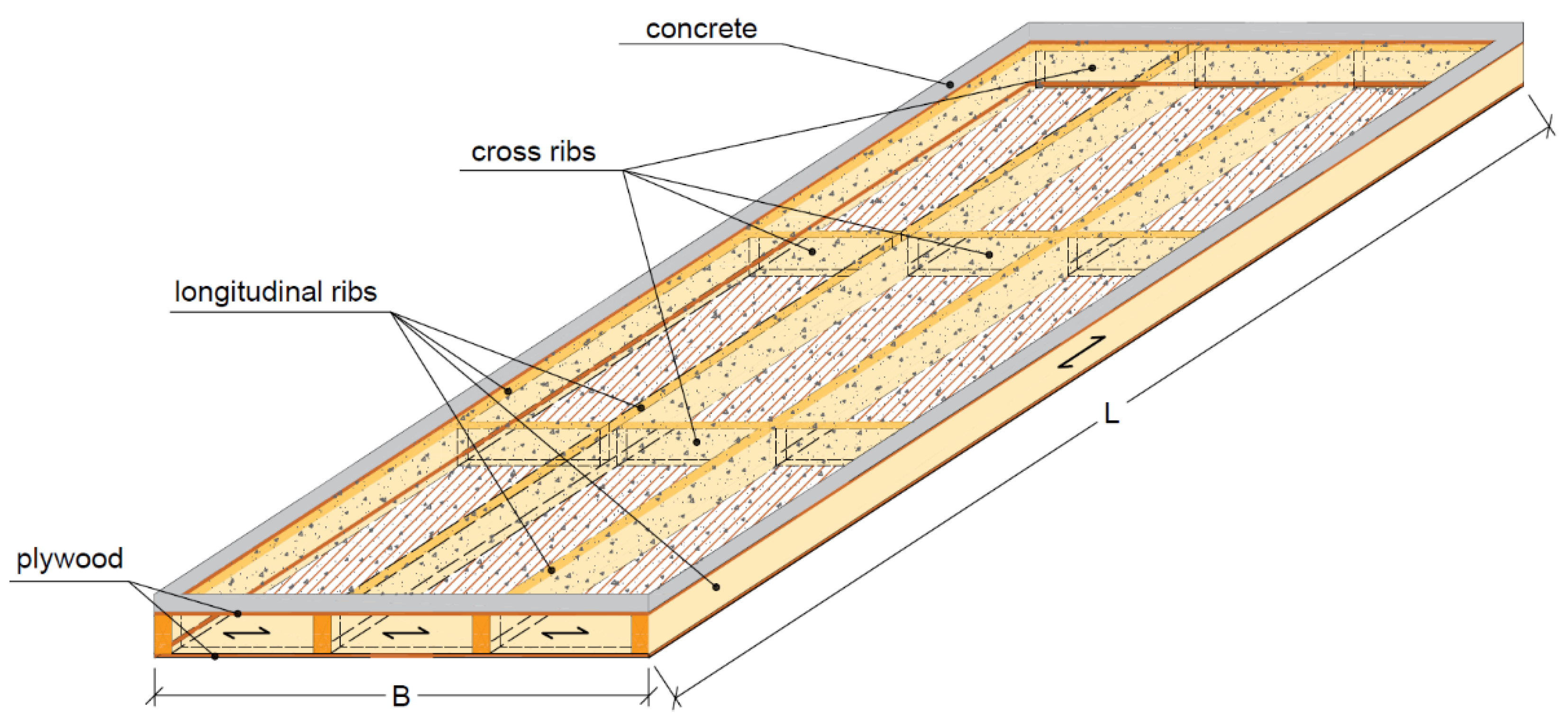
29]. Therefore, this research aims to optimise the structural solution of the timber–concrete composite by proposing a timber–concrete cross-section with a box-shaped plywood rib panel, where the lower plywood layer can increase the total bending stiffness of the cross-section several times compared with TCC with the same height timber beams and move the neutral axis of the cross-section away from the concrete layer. Thus, for example, at a span of nine meters, an 18 mm thick lower plywood layer can reduce the timber beam (rib) height maintaining the same level of bending by approximately 1.5 times. To determine the benefits of the proposed TCC solution, a comparison between the TCC with a plywood panel and the classic one with CLT is made. Because timber–concrete composite structures consist of distinct materials with quite different properties, especially in terms of weight, the consumption of material for mutual comparison of structures cannot be used as it does not fully reflect the situation. Therefore, it is necessary to use another parameter that can bind diverse types of materials in different variable proportions. The efficiency of structures made of several materials can be reflected in the prices of the materials used. Cost-based criteria are often used for structural optimizations [30,31]. The cost-effectiveness criterion—cost factor c, based on the cost per square meter of the materials for a timber–concrete composite panel, is proposed for use because of the high cost difference between CLT and concrete materials.

2. Materials and Methods

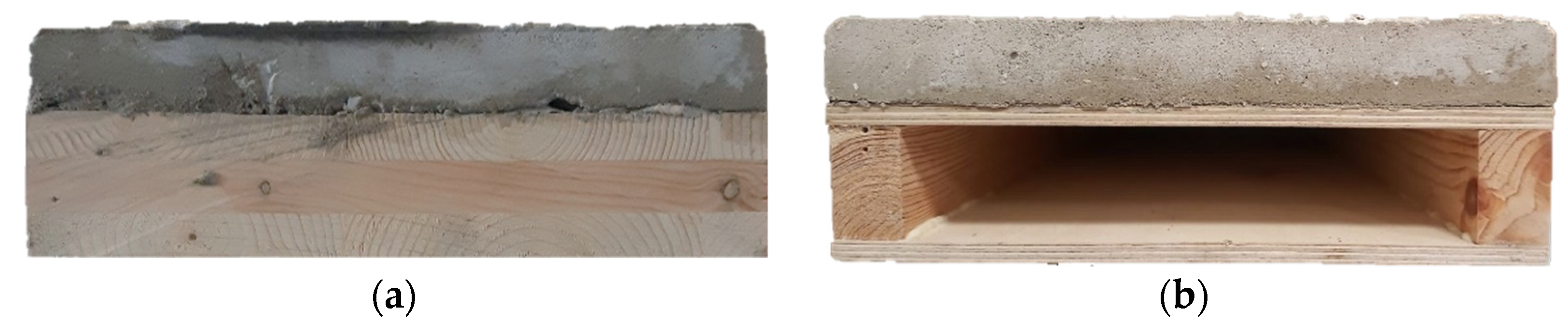
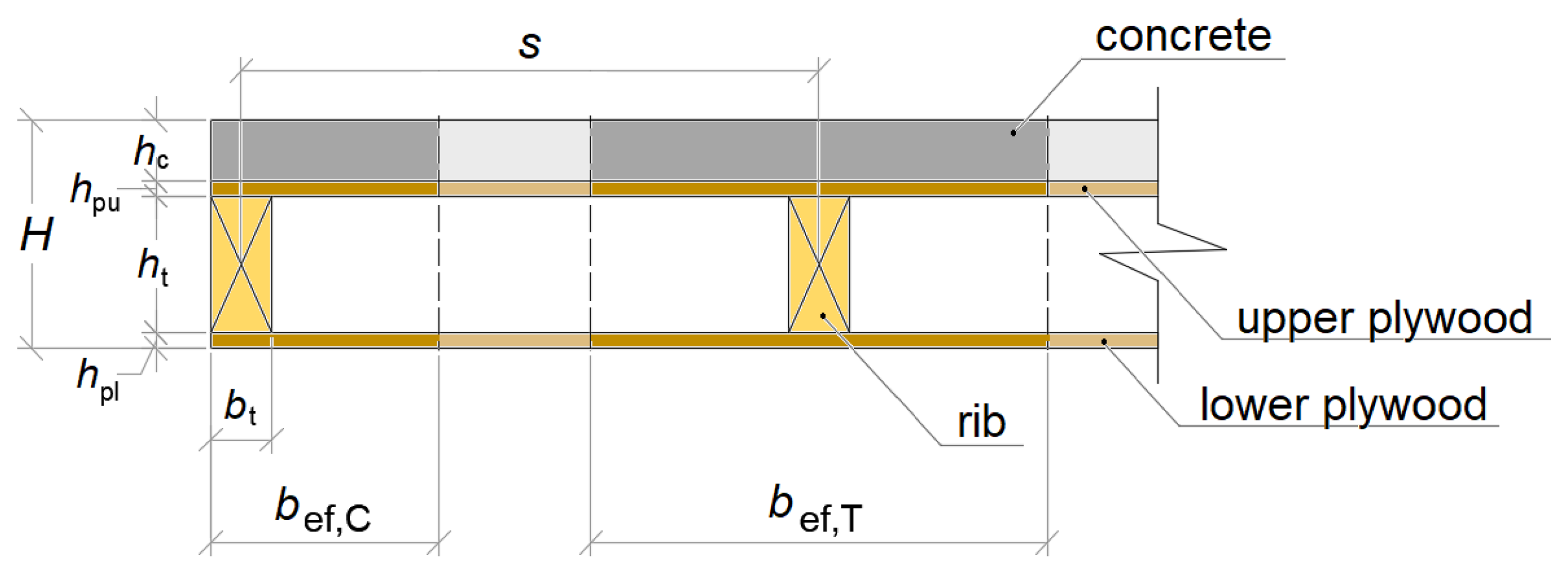
The cross-sections of the classic TCC solution with CLT base and the proposed solution—with a plywood rib panel—are shown in Figure 2. The proposed solution can effectively integrate utilities and other solutions in the cross-section of the structure without losing the height of the floor as opposed to the classical solution.
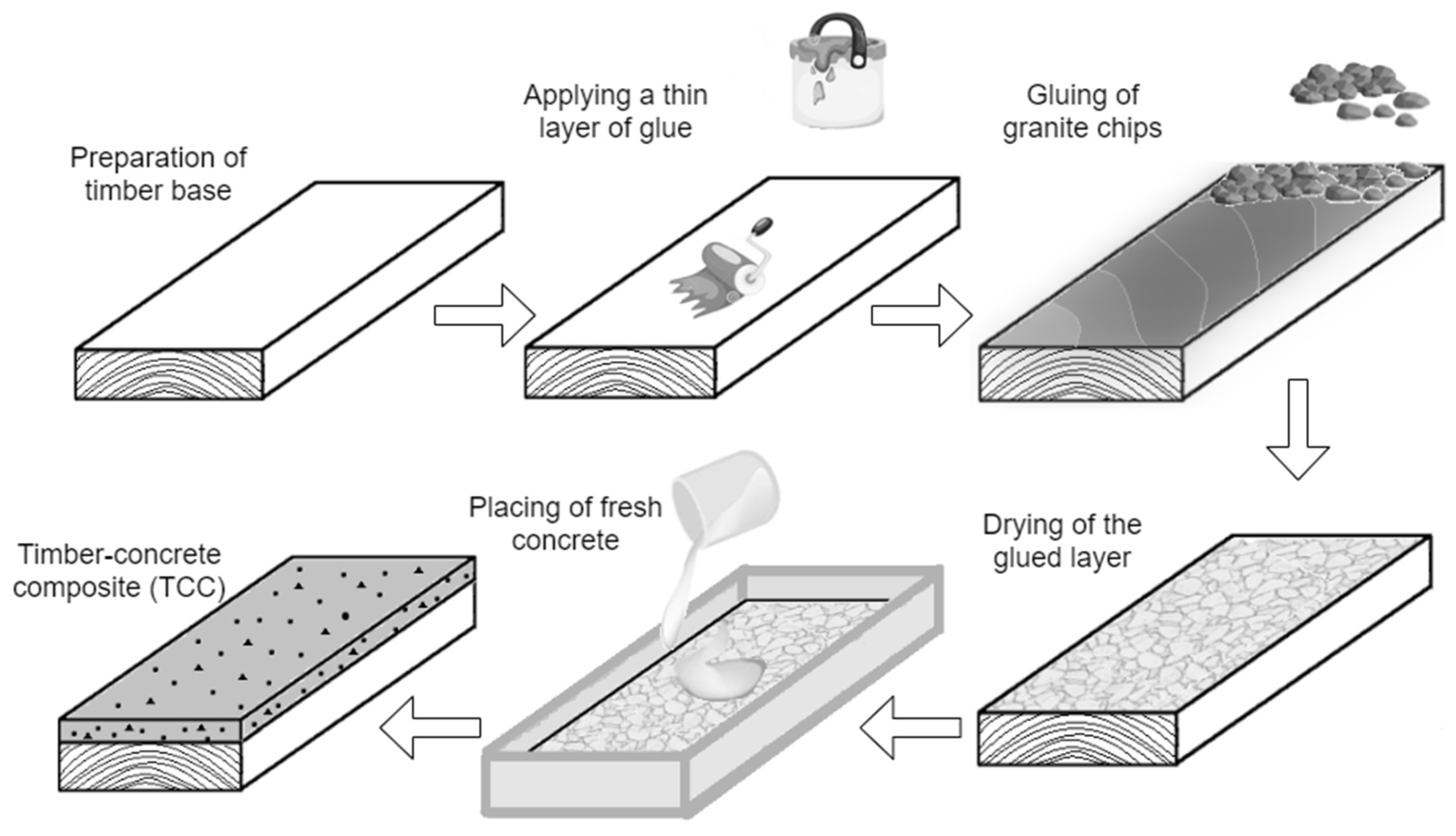
A fibre-reinforced concrete layer and a rigid connection between timber and concrete layers are assumed to compare both solutions. A schematic illustration of the rigid connection between timber and concrete components realisation is shown in Figure 3.
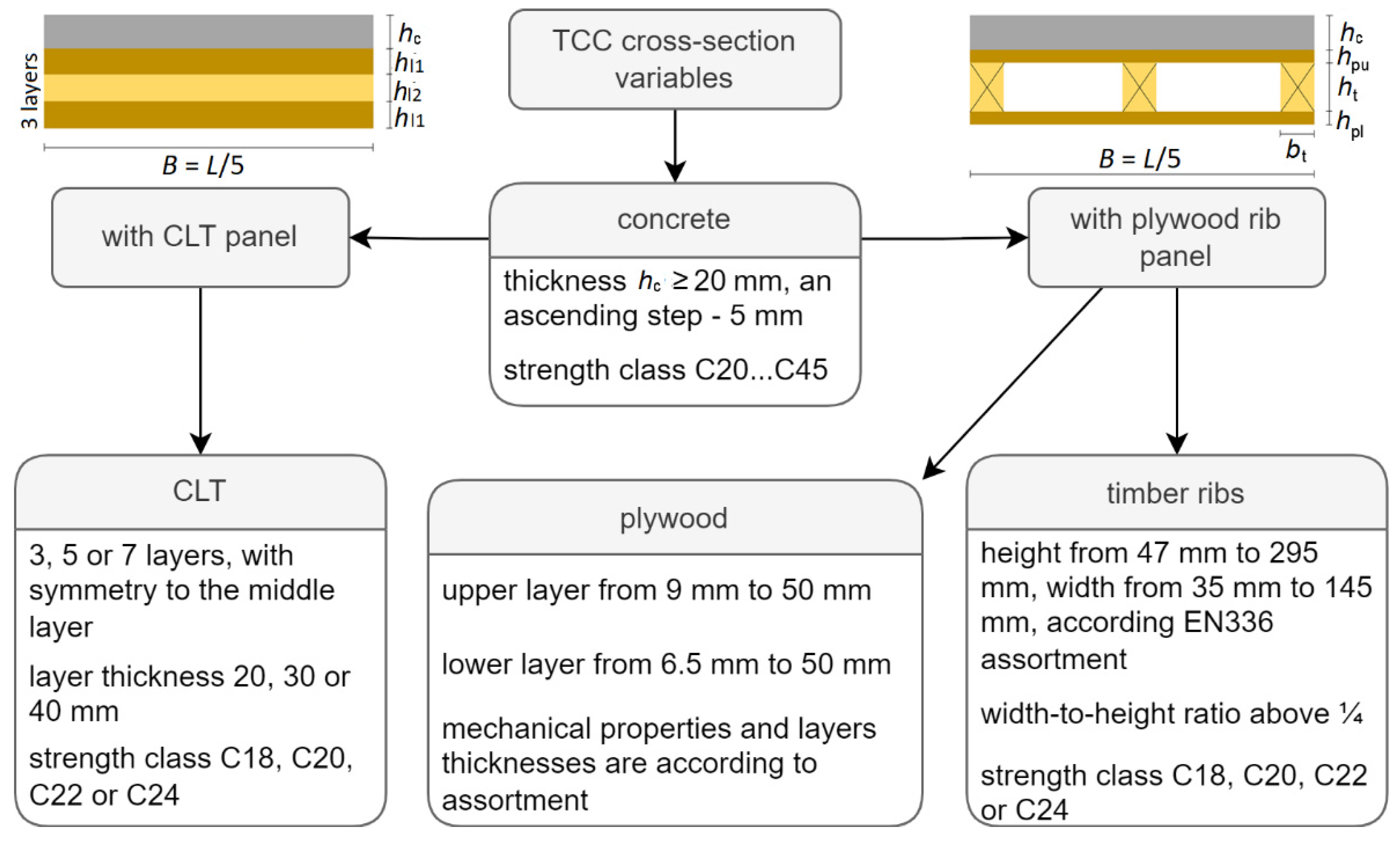
TCC panels are considered one-way, simply supported, with a width-to-span ratio of 1:5. The total width of the floor used in the vibration analysis is assumed to be 5 m. The most rational parameters for the two types of cross-sections are set for panels with a span of 3 to 10 m in steps of 0.5 m of A (residential) and B (office) category buildings. The assumed TCC cross-sectional variables include 6 different concrete and 4 different timber strength classes; 13 standard thicknesses of plywood; 3 different CLT layer thicknesses applicable to CLT panels with a total layer amount of 3, 5 or 7 layers; and 6 widths and 11 heights for timber beams according to the EN336 assortment. These are summarised in Figure 4.
The structural design of the timber–concrete composite floor panels is carried out by the recommendations of the new design rules for timber–concrete composite structures currently being developed under CEN TC250/N2330 “Eurocode 5: Design of Timber Structures—Structural design of timber–concrete composite structures—Common rules and rules for buildings”, part of which are also described in [10] and new design rules for floor vibration currently being developed under CEN TC250/SC5 WG3 Subgroup 4 “Vibrations”.
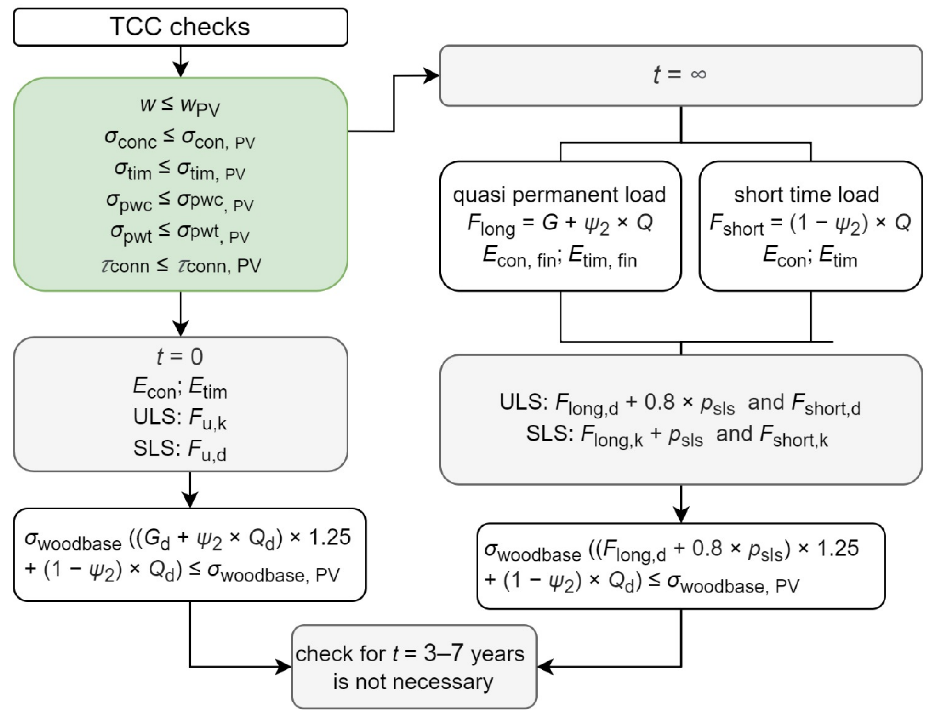
The timber–concrete composite panel is calculated for two time points. The first one, t = 0 years, corresponds to the initial state. At this time point, neither the concrete shrinkage nor the materials creep are considered in the calculations, as they have not developed. The second time point, t = ∞ years, corresponds to the end of the structure’s service life. For the long-term condition, the creep and the concrete shrinkage are considered. Effective values of the elastic modulus evaluate the creep of materials. The fictitious load from an inelastic deformation evaluates concrete’s drying and autogenous shrinkage. The deflection and stress level criteria with the respective load combinations and elastic modulus checked for the TCC panels are summarised in Figure 5. An additional check of the stress level is necessary for the wood-based elements to determine the need for a calculation at a time point corresponding to t = 3–7 years.
The effective values of the elastic modulus of concrete and timber used for long-term load calculations should be determined according to Equations (1) and (2).
E con , fin = E con , t 0 1 + ψ con × φ ( , t 0 ) ,
E tim , fin = E tim 1 + ψ tim × k def ,
where Econ,fin and Etim,fin are, respectively, the effective value of the elastic modulus of concrete and timber for long-term calculations, MPa; Econ,t0 is the modulus of elasticity of concrete at the moment when the concrete reaches the design strength or the load is applied to the concrete for the first time, MPa; ψcon is the coefficient taking into account the effect of the composite action of the material on the effective creep coefficient of concrete, which in the case of service class 1 and full composite action is taken as interpolation of recommended in the new design rules for TCC values and can be obtained by Equation (5); φ(∞,t0) is creep coefficient for long-term condition and can be obtained by Equation (3); Etim is mean value of elastic modulus of timber, MPa; ψtim = 1 is a factor that takes into account the effect of the composite action of the material on the effective creep factor of the wood; and kdef is a factor for the evaluation of creep deformation taking into account the relevant service class according to Eurocode 5.
It is assumed that the load is applied to the concrete after reaching its design strength, i.e., not earlier than 28 days from the moment of concrete placing, the relative humidity of the environment is equal to 40%, and service class 1. The creep coefficient of concrete for the long-term condition, when creep is fully developed, is calculated following Annex B of Eurocode 2 according to the following equation:
φ ( , t 0 ) = 16.8 f cm × 1 0.1 + t 0 0.20 × φ RH ,
where φ(∞,t0) is the creep coefficient for the long-term condition; fcm is the mean compressive strength of concrete at the age of 28 days, MPa; t0 is the time when a load is applied on the structure, days; φRH is a factor considering the effect of relative humidity on the creep coefficient, which can be calculated from Equation (4).
φ RH = 1 + 1 R H / 100 0.1 × h 0 3   f o r   f c m 35   MPa φ RH = [ 1 + 1 R H / 100 0.1 × h 0 3 × ( 35 f cm ) 0.7 ] × ( 35 f cm ) 0.2   for   f cm > 35   MPa ,
where RH is the relative humidity of the ambient environment, %; h0 is the notional size of the member equal to the height of the concrete layer, mm; fcm is the mean compressive strength of concrete at the age of 28 days, MPa.
ψ c o n = 0.3 × φ ( , t 0 ) + 0.75 ,
where ψcon is the coefficient considering the effect of the composite action of the material on the effective creep coefficient of concrete, in the case of service class 1 and full composite action; φ(∞, t0) is the creep coefficient for a long-term condition.
Inelastic deformations due to concrete shrinkage are considered in the calculation as a fictitious load assumed as a permanent load:
p sls = ε sh × C p , sls ,
where psls is the fictitious load, kN/m; εsh is the concrete’s drying and autogenous shrinkage inelastic deformation at the 90% level, which in the case of the cement of strength class CEM 42,5 N can be calculated from Equation (7); Cp,sls is the coefficient, which for TCC with rigid connection between timber and concrete layers, i.e., the coefficient of composite action γ = 1, can be calculated from Equation (8).
ε sh = 0.9 × [ 561 × exp ( 0.12 × f cm 10 ) × 1.55 × ( 1 ( R H R H 0 ) 3 ) + 2.5 × ( f ck 10 ) ] × 10 6 ,
where fcm is the mean compressive strength of concrete at the age of 28 days, MPa; RH is relative humidity of the ambient environment, %; RH0 = 100%; fck is the characteristic compressive strength of the concrete at the age of 28 days, MPa.
C p , sls = π 2 × E 1 × A 1 × E 2 × A 2 × z ( E 1 × A 1 + E 2 × A 2 ) × L 2 ,  
where E1 and A1 are, respectively, the elastic modulus and area of concrete cross-section, kNm2 and m2; E2 and A2 are, respectively, the elastic modulus and area of timber base cross-section, kNm2 and m2; z is the distance of the centres of gravity of the concrete and timber base cross-sections, m; L is the span of the panel, m.
The tensile strength of the concrete is completely ignored in the calculations. The timber–concrete composite panel is designed to subject the concrete layer only to compressive stresses. The shear deformation is also dismissed because of the considerable panel length to height ratio (about 30). The cross-layers of the CLT panel are evaluated in the calculations by transforming them to the material properties of the longitudinal layers according to the transformed-section method [32].
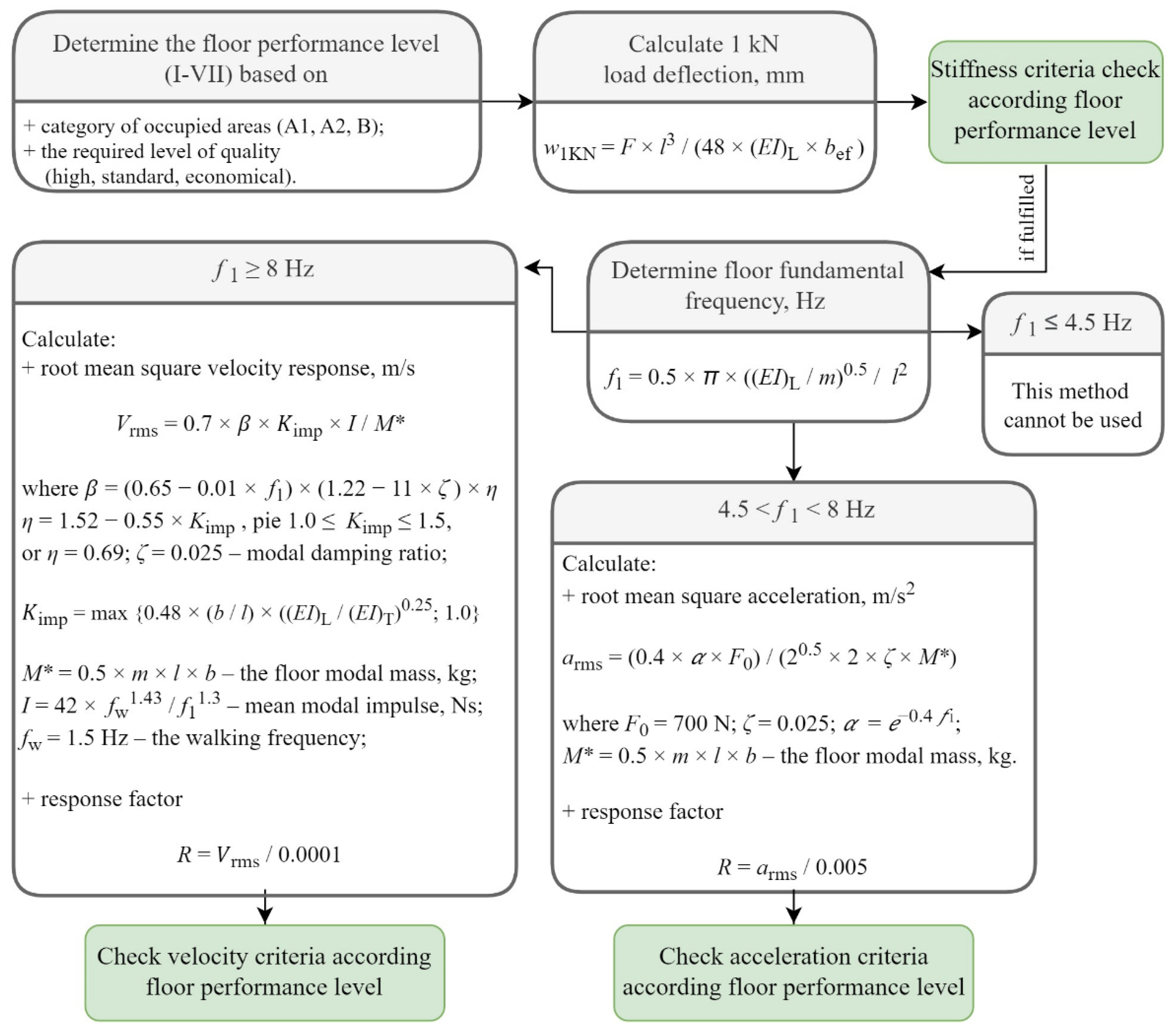
The serviceability limit state includes the determination of instantaneous and final maximum displacements and vibration criteria. According to the forthcoming rules, vibration checks consist of stiffness criteria (point load deflection) and acceleration or velocity criteria. The new rules lay down design conditions for natural frequencies between 4.5 and 8 Hz, where the floor must meet the acceleration criterion. For floors with a natural frequency larger than 8 Hz, a velocity criterion is introduced. In addition, the concept of floor performance level has been submitted, which provides for different thresholds by which to meet the vibration criteria, depending on the building category and the quality level chosen. In the calculations assumed, the floor vibration quality level is the highest. The vibration design procedure for timber–concrete composite floors with spans l, width b and self-mass per square meter m, effective bending stiffnesses for a 1 m wide strip (EI)L and (EI)T, respectively, in the longitudinal and transverse directions of the floor, is shown in Figure 6.
The limit values for all vibration criteria according to the floor performance level and the determination of the floor performance level according to the floor area use category and the required quality level are summarised in Table 1 and Table 2, respectively.
TCC with plywood rib panel structural design includes such checks of the ultimate limit state as a check of normal stresses in the concrete layer, both plywood layers and the longitudinal timber ribs, and analysis of shear stresses in the connection between the rib and the plywood. Ultimate limit state check and calculation of the panel deflection are made for two types of effective panel cross-sections—double-T and C-type cross-sections (see Figure 7). Equivalent panel bending stiffness for a 1 m wide strip is used for vibration tests.
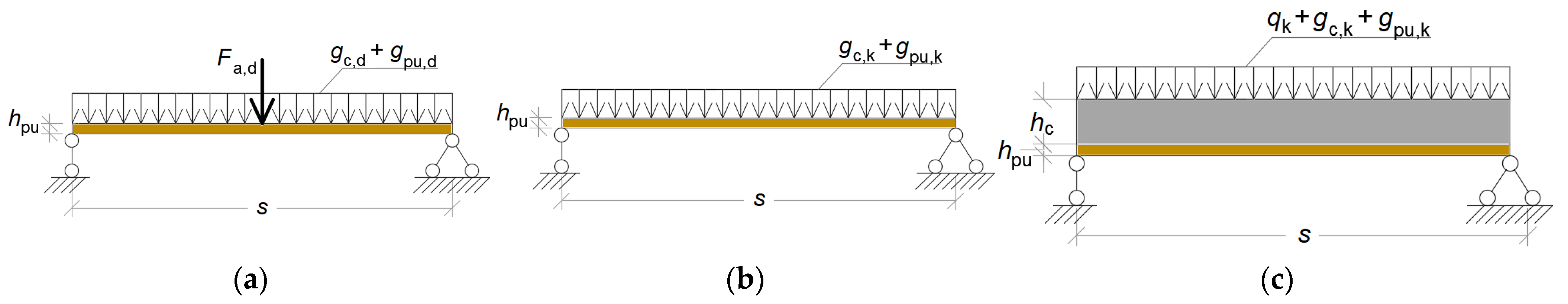
The step of longitudinal ribs s, taken based on upper plywood layer load-bearing capacity and deflection calculations in the transverse direction of the panel according to design schemes shown in Figure 8a,b, and deflection calculations of concrete and upper plywood layers with full-composite action according to design scheme shown in Figure 8c. Given the importance of upper plywood layer work between the ribs and the low entire stiffness of the wood-based materials, a more conservative design scheme for this sub-element has been adopted, i.e., a simply supported beam.
The interaction of the concrete layer with the upper plywood layer protects the latter from durability issues. The cross ribs are only used to divide the panel into smaller open-air volumes. The number of cross rib rows equals the number of longitudinal ribs, as can be seen in Figure 9.
All cross-sections of the two types of TCC are generated according to the input and variable data using the calculation algorithm developed in the Hypertext Preprocessor (PHP) environment. The generated cross-sections are passed through the ultimate and serviceability limit tests. Cross-sections that do not meet at least one of the checks are discarded. The cross-sections that satisfy all the tests are arranged according to the criterion of rationality.
The cost factor c as the criterion of rationality for TCC with CLT panel base is calculated according to the equation:
c = h CLT × P CLT + h c × P c P c , C 20 × B 1 ,
where hCLT and hc are, respectively, CLT and concrete layer heights, m; PCLT and Pc are, respectively, CLT and usable strength class concrete price, EUR/m3; Pc, C20 is the price of concrete of strength class C20, used as the base price, EUR/m3; B1 is a one-meter-wide strip of the panel, m.
For the comparison of CLT–concrete composite panels, the price of one cubic meter of CLT is assumed to be 900 EUR, while the cost per cubic meter of C20 strength concrete with 0.5% synthetic fibres Strux 40/90 is considered to be 104 EUR. The prices accepted for the other concrete strength classes and the Pc/Pc,C20 ratios are summarised in Table 3. The prices used for the analysis are based on the Latvian market at the turn of the year 2021/2022. The use of additional protection layers—for example, fire-rated plasterboards- is required to meet the fire safety requirements of both CLT and plywood panel solutions. This solution allows the relatively easy replacement of such layers if it is necessary in comparison with charred CLT floor solution without additional protection layer. Fire protection layers are not considered in the cost factor analysis.
The cost factor c for TCC with plywood rib panel base is calculated according to the equation:
c = ( h pu × P pu + h pl × P pl + h c × P c ) × b × L + h t × b t × P t × ( L × n long + b × n trans ) b × L × P c , C 20 × B 1
where hi is the height of the layer or rib; Pi is the price of the respective material, EUR/m3; b and L are, respectively, panel width and span, m; nlong and ntrans are the number of longitudinal and transverse ribs; indexes pu, pl are, respectively, the upper and lower plywood layers; indexes t and c are, respectively, the timber and concrete layers; Pc,C20 is the price of concrete of strength class C20, used as the base price, EUR/m3; B1 is a one-meter-wide strip of the panel, m.
The price per cubic meter of timber is assumed to be 600 EUR. Based on its thickness, plywood prices per cubic meter are summarised in Table 4.

3. Results

Figure 10 shows a graphical representation of the results at a span of 7 meters for a CLT–concrete panel with a high vibration quality class suitable for use in category A1, i.e., multi-storey residential buildings. An amount of 966 generated CLT–concrete cross-section variants passed through all TCC stress, deflection, and vibration checks.
According to the applied criterion of rationality, the cross-section with the lowest cost factor corresponding to a height of 180 mm is selected as the most rational cross-section from the results shown in Figure 10. In addition, the results with the lowest height at the corresponding lowest cost factor value may be of interest.
The determined rational cross-sectional parameters for TCC with CLT panel at two load area categories—A1 and B, with uniformly distributed load values of 2 kN/m2 and 3 kN/m2, respectively, and the highest quality vibration class are summarised in Table 5 and Table 6. In most cases, the check of long-term deformation for the CLT–concrete panels, which is marked as wfin,ratio and means the ratio of the calculated deflection to the limiting value accepted as 1/150 of the span, is crucial.
In the case of the TCC with plywood rib panel, for the most part, the vibration criterion, which is marked as vib_Rratio and means the ratio of the calculated response factor R to the limit value according to the Table 1 and Table 2, is decisive. The determined most cost-effective cross-sectional parameters for the plywood–concrete panel at two load area categories—A1 and B—are summarised in Table 7 and Table 8.
The most cost-effective cross-sections for CLT–concrete composite panels with spans from 3 to 10 meters in 0.5 m increments are compared to the cross-sections of plywood-concrete composite panels in two ways. The first case corresponds to the most cost-effective cross-section of a plywood-concrete composite with the related panel height. The second case compares the cross-section of a plywood-concrete composite panel with the minimum possible height and the corresponding lowest cost factor. Figure 11 and Figure 12 summarise the data obtained for multi-storey residential and office buildings.
A comparison of the 1-meter-wide strip self-weight of TCC with CLT base and equivalent self-weight of TCC with plywood rib panel base with the most cost-effective cross-sectional parameters is shown in Figure 13.

4. Discussion

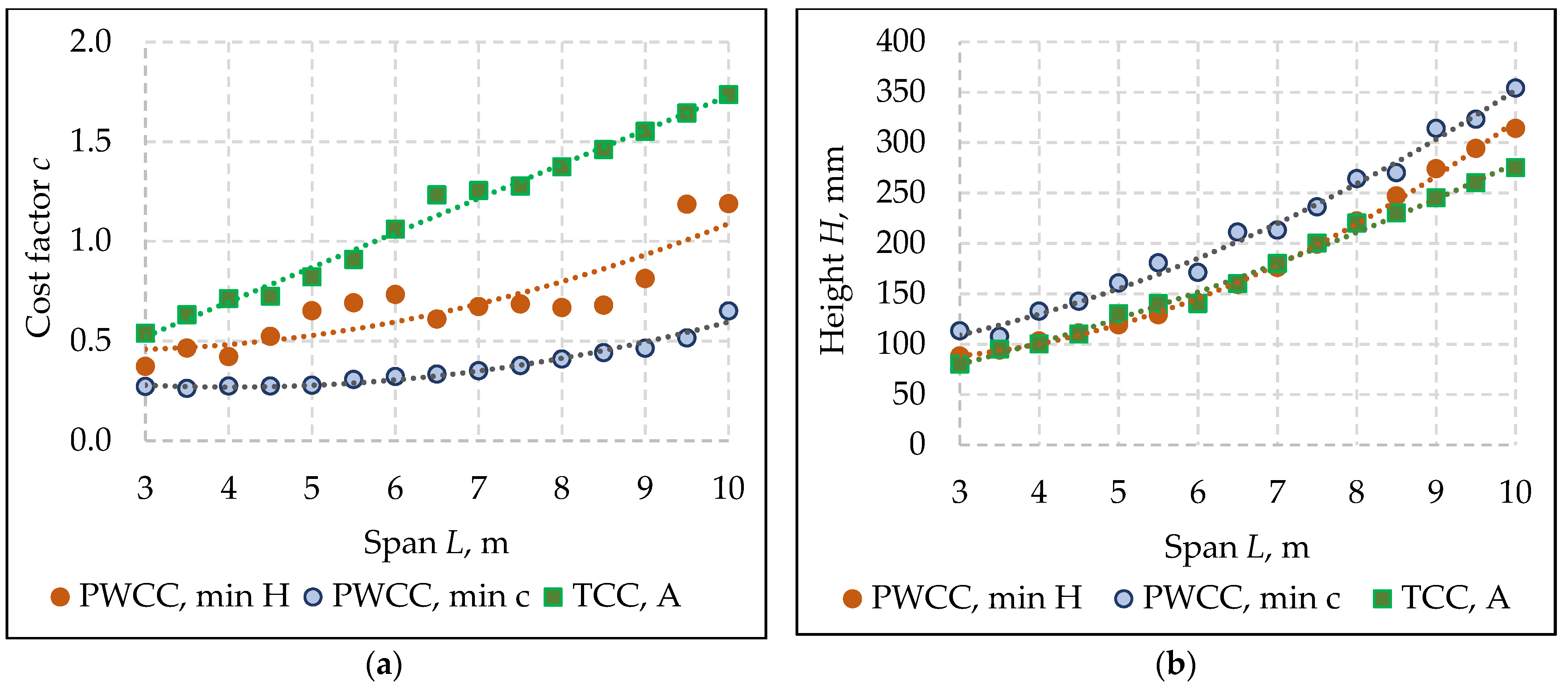
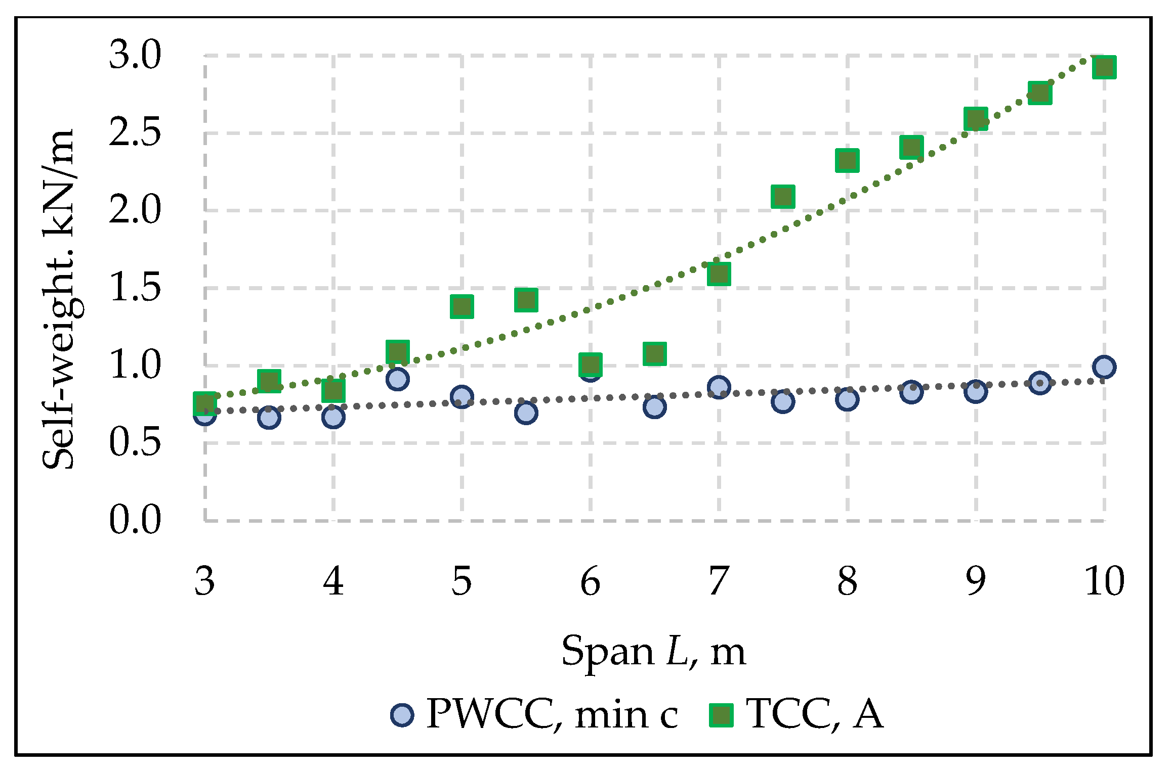
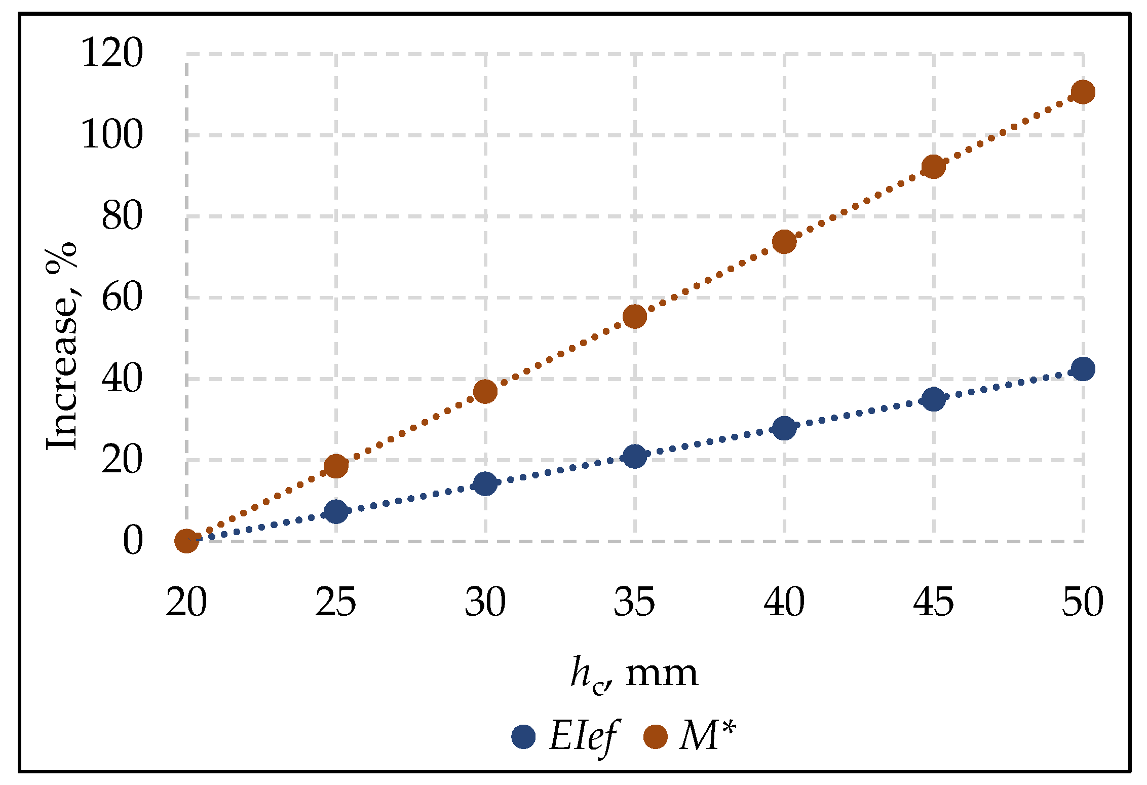
The proposed alternative solution of the timber–concrete composite panel with a plywood rib panel can significantly reduce the cost factor. Compared with the CLT–concrete panel, the cost factor of the plywood–concrete panel with the most cost-effective cross-section for the building category A1 is from 50% to 73% lower, with an average value of 66%. A significant reduction in the cost factor leads to increased plywood–concrete composite panel height from 7% to 41%, with an average value of 25% compared with CLT–concrete composite panels. Due to the structure of the proposed solution, thicker concrete layers lead to the need for either a thicker upper plywood layer or/and additional ribs to reduce the step between them. Both cases are immediately associated with additional costs. Therefore, the most cost-effective plywood–concrete cross-sections are mainly with a 20 mm thick concrete layer. This solution has an additional advantage. Using a thin layer of concrete, the self-weight of the panel does not increase significantly depending on the span. The difference between plywood–concrete and CLT–concrete panel in weight is 20% for a span of three meters. It grows up to 71% for larger spans. Moreover, an increase in the concrete layer height leads to a faster increase in modal mass than an increase in bending stiffness, as shown in Figure 14. Therefore, because the determining check for plywood–concrete panels is usually vibration, an increase in the concrete layer does not always give a good result.
By choosing a plywood-concrete composite panel with the lowest possible cross-sectional height that meets the requirements for TCC checks, it is possible to reduce the difference between cross-sectional heights up to 14%. In the case of the span equal to 6 m, 12% less plywood–concrete panel height than for the CLT–concrete panel was obtained. The average value of the plywood–concrete panel height increase is 3%. The cost factor is from 21% to 31% lower for plywood–concrete panels with a smaller height than CLT–concrete panels. At heights equal to and higher than the CLT–concrete panel height, it reaches up to 54%. For spans from 6.5 m to 8 m, the cross-sectional heights of both panel types are almost the same, but the cost factor for plywood–concrete panels is 49% lower.
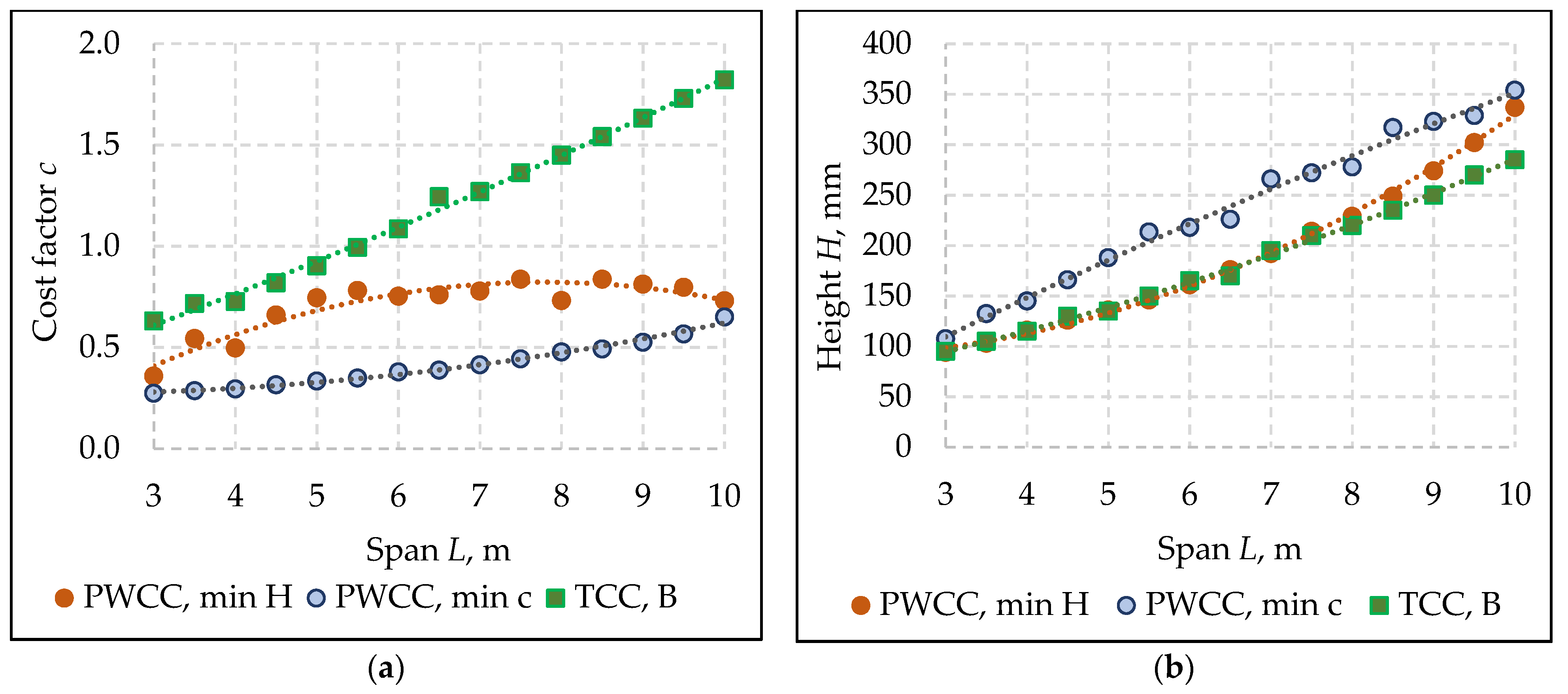
Office building floors have an analogous situation to residential buildings. The cost factor of the plywood–concrete panel with the most cost-effective cross-section is from 57% to 69% lower, with an average value of 65% compared with the CLT–concrete panel. Cost factor reduction leads to an increase of the plywood–concrete composite panel height from 13% to 43%, with an average value of 29%, compared with CLT–concrete composite panels. The difference in weight is from 15% to 67% between plywood–concrete and CLT–concrete panels with the most cost-effective cross-sectional parameters, with an average value of 45%. Choosing a plywood–concrete composite panel with the lowest possible cross-sectional height corresponding to the TCC checks, the cross-section height difference of the proposed design solution decreases by up to 18% compared with CLT–concrete composite panel height. For the spans from 3 m to 8.5 m, the heights of both panel types are almost the same—the difference is up to 6%, but the decrease in cost factor for the plywood–concrete panel is from 18% to 50%. For spans over 9.5 m, the difference in height between the most cost-effective cross-section and the lowest height cross-section of the plywood–concrete panel is less than 8%.
Thus, the proposed alternative timber–concrete composite panel design solution, based on a plywood-type panel with timber ribs, is a particularly advantageous composite panel for residential and office buildings. The proposed solution significantly reduces the floor cost compared with CLT–concrete panels, even if the height of the floor structure is essential. Without a concrete layer, a plywood panel as a stand-alone design solution results in a bouncy floor. The interaction of concrete and plywood rib panel creates a competitive floor solution.

5. Conclusions

A comparison of two types of timber–concrete composite panels–with cross-laminated timber panel and with plywood rib panel based on costs of the materials per one square meter of the panel was made. The following benefits of the proposed solution with the plywood rib panel instead of the cross-laminated panel for timber–concrete composite were identified:
  • Cost factor reduction of the most cost-effective cross-sections up to 73% for multi-storey residential and 69% for office building floors.
  • A significant reduction of the cost factors leads to an increase in the panel total height of an average of 25% for multi-storey residential buildings and 29% for office buildings.
  • Choosing a plywood–concrete composite panel with the lowest possible cross-sectional height, which requires TCC checks, makes it possible to achieve panels of comparable size height to CLT–concrete panels. Up to 54% and 69% lower cost factor values for A1 and B category buildings are obtained for panels of almost equal height.
  • Thin concrete layers can achieve the most cost-effective parameters of the plywood–concrete panels and low self-weight levels regardless of panel span.
  • The self-weight reduction of 59% un 45% on average, respectively, for A1 and B category buildings for plywood–concrete composite panels with the most cost-effective cross-sections, is obtained in comparison with CLT–concrete composite panels.
  • The proposed estimation algorithm of panel cost-effectiveness can be applied in the initial design stage, during which it is necessary to select the used structural solution and materials.

Author Contributions

Conceptualization, K.B.-V., D.S. and L.P.; methodology, K.B.-V. and D.S.; software, K.B.-V.; investigation, K.B.-V.; resources, K.B.-V.; data curation, K.B.-V.; writing—original draft preparation, K.B.-V.; writing—review and editing, K.B.-V. and D.S.; visualisation, K.B.-V.; supervision, D.S. and L.P.; funding acquisition, K.B.-V. All authors have read and agreed to the published version of the manuscript.

Funding

This work has been supported by the European Social Fund within the Project No 8.2.2.0/20/I/008 «Strengthening of PhD students and academic personnel of Riga Technical University and BA School of Business and Finance in the strategic fields of specialisation» of the Specific Objective 8.2.2 «To Strengthen Academic Staff of Higher Education Institutions in Strategic Specialization Areas» of the Operational Programme «Growth and Employment» and by Riga Technical University’s Doctoral Grant programme. Buildings 12 00761 i001

Institutional Review Board Statement

Not applicable.

Informed Consent Statement

Not applicable.

Data Availability Statement

Not applicable.

Conflicts of Interest

The authors declare no conflict of interest.

References

  1. Movaffaghi, H.; Pyykkö, J.; Yitmen, I. Value-Driven Design Approach for Optimal Long-Span Timber-Concrete Composite Floor in Multi-Storey Wooden Residential Buildings. Civ. Eng. Environ. Syst. 2020, 37, 100–116. [Google Scholar] [CrossRef]
  2. Sultana, R.; Rashedi, A.; Khanam, T.; Jeong, B.; Hosseinzadeh-Bandbafha, H.; Hussain, M. Life Cycle Environmental Sustainability and Energy Assessment of Timber Wall Construction: A Comprehensive Overview. Sustainability 2022, 14, 4161. [Google Scholar] [CrossRef]
  3. Catterou, T.; Castaing, J.-B.; Garcia, P. Simplified Computation of Timber Floor Vibrations Level Due to Human Activities. In Proceedings of the EURODYN2020, Athens, Greece, 23–26 November 2020; EASD Procedia: Athens, Greece, 2020; pp. 1896–1912. [Google Scholar]
  4. Lewis, K.; Basaglia, B.; Shrestha, R.; Crews, K. The Use of Cross Laminated Timber for Long Span Flooring in Commercial Buildings. In Proceedings of the WCTE 2016, Wiena, Austria, 22–25 August 2016; pp. 4813–4821. [Google Scholar]
  5. Hu, L.J.; Chui, Y.H.; Onysko, D.M. Vibration Serviceability of Timber Floors in Residential Construction. Prog. Struct. Eng. Mater. 2001, 3, 228–237. [Google Scholar] [CrossRef]
  6. Opazo-Vega, A.; Muñoz-Valdebenito, F.; Oyarzo-Vera, C. Damping Assessment of Lightweight Timber Floors Under Human Walking Excitations. Appl. Sci. 2019, 9, 3759. [Google Scholar] [CrossRef] [Green Version]
  7. Dias, A.; Skinner, J.; Crews, K.; Tannert, T. Timber-Concrete-Composites Increasing the Use of Timber in Construction. Eur. J. Wood Wood Prod. 2016, 74, 443–451. [Google Scholar] [CrossRef]
  8. Crews, K.; John, S.; Gerber, C.; Buchanan, A.; Smith, T.; Pampanin, S. Innovative Engineered Timber Building Systems for Nonresidential Applications, Utilising Timber Concrete Composite Flooring Capable of Spanning up to 8 to 10 m; Forest & Wood Products Australia Limited.: Melbourne, VC, Australia, 2010; p. 52. [Google Scholar]
  9. Selle, R.; Holschemacher, K.; Heiden, B. An Alternative Approach for Hybrid Floors Made of Timber and Concrete (TCCS). In Modern Building Materials, Structures and Techniques, Proceedings of the 10th International Conference, Vilnius, Lithuania, 19–21 May 2010; Vilnius Gediminas Technical University: Vilnius, Lithuania, 2010; pp. 778–786. [Google Scholar]
  10. COST Action FP1402. Design of Timber-Concrete Composite Structures: A State-of-the-Art Report by COST Action FP1402/WG 4, 1st ed.; Dias, A., Schänzlin, J., Dietsch, P., Eds.; Shaker Verlag: Aachen, Germany, 2018; ISBN 9783844061451. [Google Scholar]
  11. Dias, A.; Fragiacomo, M.; Harris, R.; Kuklík, P.; Rajčić, V.; Schänzlin, J. Eurocode 5: Design of Timber Structures–Structural Design of Timberconcrete Composite Structure—Common Rules and Rules for Buildings; 2019; in press. [Google Scholar]
  12. Ghiami Azad, A.R.; Kreitman, K.; Engelhardt, M.; Helwig, T.; Williamson, E. A Technique for Strengthening Existing Continuous Non-Composite Steel Girder Bridges Using Post-Installed Shear Connectors and Inelastic Moment Redistribution. In Proceedings of the 39th IABSE Symposium—Engineering the Future, Vancouver, BC, Canada, 21–23 September 2017; pp. 1217–1224. [Google Scholar]
  13. Ceccotti, A.; Fragiacomo, M.; Giordano, S. Long-Term and Collapse Tests on a Timber-Concrete Composite Beam with Glued-in Connection. Mater. Struct. 2007, 40, 15–25. [Google Scholar] [CrossRef]
  14. Tannert, T.; Endacott, B.; Brunner, M.; Vallée, T. Long-Term Performance of Adhesively Bonded Timber-Concrete Composites. Int. J. Adhes. Adhes. 2017, 72, 51–61. [Google Scholar] [CrossRef]
  15. Fragiacomo, M.; Lukaszewska, E. Development of Prefabricated Timber–Concrete Composite Floor Systems. Proc. Inst. Civ. Eng. Struct. Build. 2011, 164, 117–129. [Google Scholar] [CrossRef] [Green Version]
  16. Rodrigues, J.N.; Dias, A.M.P.G.; Providência, P. Timber-Concrete Composite Bridges: State-of-the-Art Review. BioResources 2013, 8, 6630–6649. [Google Scholar] [CrossRef] [Green Version]
  17. Buka-Vaivade, K.; Serdjuks, D.; Podkoritovs, A.; Pakrastins, L.; Mironovs, V. Rigid Connection with Granite Chips in the Timber-Concrete Composite. Environ. Technol. Resour. Proc. Int. Sci. Pract. Conf. 2021, 3, 36–39. [Google Scholar] [CrossRef]
  18. Buka-Vaivade, K.; Serdjuks, D. Behavior of Timber-Concrete Composite with Defects in Adhesive Connection. Procedia Struct. Integr. 2022, 37, 563–569. [Google Scholar] [CrossRef]
  19. Holschemacher, K.; Kieslich, H. Recent Developments in Timber-Concrete Composite. In Proceedings of the CLEM+CIMAD 2017, Junin, Argentina, 17–19 May 2017; p. 9. [Google Scholar]
  20. Lamothe, S.; Sorelli, L.; Blanchet, P.; Galimard, P. Engineering Ductile Notch Connections for Composite Floors Made of Laminated Timber and High or Ultra-High Performance Fiber Reinforced Concrete. Eng. Struct. 2020, 211, 110415. [Google Scholar] [CrossRef]
  21. Holschemacher, K.; Klotz, S.; Weisse, D. Application of Steel Fibre Reinforced Concrete for Timber-Concrete Composite Constructions. In System-Based Vision for Strategic and Creative Design, Proceedings of the 2nd International Conference, Rome, Italy, 23–26 September 2003; Balkema Publishers: Amsterdam, The Netherlands, 2003; Volume 2, pp. 161–170. [Google Scholar]
  22. Holý, M.; Vráblík, L.; Petřík, V. Analysis of the Connection of the Timber-Fiber Concrete Composite Structure. IOP Conf. Ser. Mater. Sci. Eng. 2017, 236, 012067. [Google Scholar] [CrossRef] [Green Version]
  23. Lau, C.; Chegenizadeh, A.; Htut, T.; Nikraz, H. Performance of the Steel Fibre Reinforced Rigid Concrete Pavement in Fatigue. Buildings 2020, 10, 186. [Google Scholar] [CrossRef]
  24. Vougioukas, E.; Papadatou, M. A Model for the Prediction of the Tensile Strength of Fiber-Reinforced Concrete Members, Before and After Cracking. Fibers 2017, 5, 27. [Google Scholar] [CrossRef] [Green Version]
  25. Buka-Vaivade, K.; Sliseris, J.; Serdjuks, D.; Pakrastins, L.; Vatin, N. Rational Use of HPSFRC in Multi-Storey Building. Mag. Civ. Eng. 2018, 84, 3–14. [Google Scholar] [CrossRef]
  26. Meza, A.; Pujadas, P.; Meza, L.M.; Pardo-Bosch, F.; López-Carreño, R.D. Mechanical Optimization of Concrete with Recycled PET Fibres Based on a Statistical-Experimental Study. Materials 2021, 14, 240. [Google Scholar] [CrossRef] [PubMed]
  27. Pawelska-Mazur, M.; Kaszynska, M. Mechanical Performance and Environmental Assessment of Sustainable Concrete Reinforced with Recycled End-of-Life Tyre Fibres. Materials 2021, 14, 256. [Google Scholar] [CrossRef]
  28. Huber, C.; Deix, K. Comparison of Calculation Methods of Elastic Bonding: Limits of the Gamma Method Using an Example of a Wood–Concrete Composite Floor with Single Loads. Materials 2021, 14, 7211. [Google Scholar] [CrossRef]
  29. Negrão, J.; Jorge, L. CLT Structures for Long Span Floors and Roofs—Optimizing the Cross-Section Properties. In Proceedings of the 41st IAHS World Congress, Albufeira, Portugal, 13–16 September 2016; p. 11. [Google Scholar]
  30. Majer, J.; Vavřínová, N.; Stejskalová, K.; Pentková, L. Software for the Multi-Criteria Design of the External Walls Based on User Priority. Buildings 2022, 12, 647. [Google Scholar] [CrossRef]
  31. Kravanja, S.; Žula, T. Cost Optimization of Structures in Civil Engineering. In Proceedings of the Proceedings of the New Developments in Structural Engineering and Construction, Pittsburgh, PA, USA, 2–4 May 2013; Research Publishing Services: Singapore, 2013; pp. 1325–1330. [Google Scholar]
  32. Buka-Vaivade, K.; Serdjuks, D.; Goremikins, V.; Vilguts, A.; Pakrastins, L. Experimental Verification of Design Procedure for Elements from Cross-Laminated Timber. Procedia Eng. 2017, 172, 1212–1219. [Google Scholar] [CrossRef]
Figure 1. The proposed production method of the rigid connection between timber and concrete layers by gluing granite chips.
Buildings 12 00761 g001
Figure 2. Cross-section of timber–concrete composite (TCC) with: (a) cross-laminated timber (CLT); (b) plywood rib panel.
Buildings 12 00761 g002
Figure 3. The proposed production method of a rigid connection between timber and concrete layers [18].
Buildings 12 00761 g003
Figure 4. The assumed variables for elements of the TCC cross-section, where B—width of the panel; L—length of the panel; hc—thickness of the concrete layer; hl1 and hl2—thickness of the CLT layers; hpu and hpl—thickness of the upper and lower plywood layers; bt and ht—width and height of the timber rib.
Buildings 12 00761 g004
Figure 5. TCC checks with corresponding load combinations, where ULS and SLS are ultimate and serviceability limit states; t—time point; w—deflection; σ—normal stresses; τ—shear stresses; E—elastic modulus; G—dead load; Q—live load; ψ2—share of the permanent live load at the total live load; Fu—fundamental load combination; psls—fictitious load evaluated shrinkage; indexes: PV—permissible value; conc—concrete; tim—timber; pwc—upper plywood layer; pwt—lower plywood layer; conn—the connection between the rib and upper plywood layer; k—characteristic values; d—design values; fin—effective values; woodbase—wood-based materials.
Buildings 12 00761 g005
Figure 6. The algorithm of the vibration checks according to the forthcoming design rules “Vibrations.
Buildings 12 00761 g006
Figure 7. Two types of effective sections for calculations, where H—the height of the panel; hc—the height of the concrete layer; hpu and hpl—the height of the upper and lower plywood layers; ht—the height of the timber rib; bef, T is the effective width of the double-T section, equal to the smallest of a tenth of the panel span L with rib width bt and half of rib step s; the effective width of the C-type section bef,C is half of bef,T with ½ bt.
Buildings 12 00761 g007
Figure 8. Design schemes for: (a) the load-bearing capacity of the upper plywood layer per 80 kg assembly load Fa,d and self-weight from concrete gc,d and plywood layers gpu,d; (b) the deflection of the upper plywood layer from the self-weight of concrete gc,k and plywood layers gpu,k; (c) the deflection of the concrete and top plywood layers from the self-weight of both layers and the useful uniformly distributed load qk, where s is the rib step; hc and hpu are thicknesses of concrete and upper plywood layers.
Buildings 12 00761 g008
Figure 9. The view of timber–concrete composite with plywood rib panel with four longitudinal ribs and four rows of cross ribs.
Buildings 12 00761 g009
Figure 10. All possible results as the panel’s height with the related cost factor, which correspond to the ultimate and serviceability limit states for a CLT–concrete composite panel with a span of 7 m.
Buildings 12 00761 g010
Figure 11. CLT–concrete (CLTCC) and plywood–concrete (PWCC) panels in category A1 buildings: (a) cost-factor dependence of the panel span; (b) panel-height dependence of its span, where min H—panel with the lowest height at the corresponding lowest cost factor; min c—panel with the most cost-effective cross-section, and A—multi-storey residential building.
Buildings 12 00761 g011
Figure 12. CLT–concrete (CLTCC) and plywood–concrete (PWCC) panels in category B buildings: (a) cost-factor dependence of the panel span; (b) panel-height dependence of its span, where min H—panel with the lowest height at the corresponding lowest cost factor; min c—panel with the most cost-effective cross-section, and B—office building.
Buildings 12 00761 g012
Figure 13. Self-weight of 1 m wide strip dependence of the panel span for CLT–concrete (CLTCC) and plywood–concrete (PWCC) panel in category A1 buildings, where min c—panel with the most cost-effective cross-section, and A—multi-storey residential building.
Buildings 12 00761 g013
Figure 14. Increase bending stiffness EIef and modal mass M* dependence of concrete layer height hc for plywood–concrete with constant plywood panel cross-section parameters.
Buildings 12 00761 g014
Table 1. Limit values for vibration criteria according to the floor performance level.
CriteriaFloor Performance Level
IIIIIIIVVVIVII
Stiffness:
w1kN (mm) ≤
0.250.50.81.21.6No
Acceleration and velocity: R481216240.5
Table 2. Floor performance level according to the category of area use and quality class.
Category of UseQuality Level
QualityBaseEconomy
Multi-storey residential, A1I, II, IIIIVV
Single house, A2I, II, III, IVVVI
Office areas, BI, IIIIIIV
Table 3. Prices of concrete with synthetic fibres depending on concrete strength class.
Strength ClassC25C30C35C40C45
Price, EUR/m3106108109110111
Pc/Pc,C201.0191.0381.0481.0581.067
Table 4. Prices of plywood depending on its thickness.
Thickness6.591215182124273035404550
Price, EUR/m312381019911895876895895895895995995995995
Ppw/Pc,C2011.909.808.768.618.428.618.618.618.619.579.579.579.57
Table 5. The most rational cross-sectional parameters of the CLT–concrete composite panel for category A1.
Span, m33.544.555.566.577.588.599.510
Height H, mm8095100110130140140160180200220230245260275
Cost factor c0.540.630.710.720.820.911.061.231.251.281.371.461.551.641.74
hCLT, mm6070808090100120140140140150160170180190
hc, mm202520304040202040607070758085
Concrete classC20C20C20C45C45C45C40C25C45C45C45C45C45C45C45
Timber classC24C20C24C24C24C24C24C22C24C24C18C22C24C24C24
Self-weight, kN/m0.750.900.841.091.381.421.001.071.592.092.322.412.592.762.92
wfin,ratio0.780.920.821.000.990.990.900.990.980.990.991.000.991.000.99
Table 6. The most rational cross-sectional parameters of the CLT–concrete composite panel for category B.
Span, m33.544.555.566.577.588.599.510
Height H, mm95105115130135150165170195210220235250270285
Cost factor c0.630.720.730.820.900.991.091.241.271.361.451.541.631.731.82
hCLT, mm70808090100110120140140150160170180190200
hc, mm252535403540453055606065708085
Concrete classC20C20C20C20C45C35C45C45C40C45C45C45C45C45C45
Timber classC24C24C24C24C24C24C24C24C24C20C24C24C24C24C24
Self-weight, kN/m0.920.961.211.381.301.461.631.341.962.132.172.342.512.802.97
wfin,ratio0.690.710.950.990.931.000.990.981.001.000.991.000.990.990.99
Table 7. The most rational cross-sectional parameters of the CLT–concrete composite panel for category A1.
Span, m33.544.555.566.577.588.599.510
Height H, mm113107.5132.5142.5161180.5171211213236264270314323354
Cost factor c0.270.260.270.270.280.310.320.330.350.380.410.440.460.510.65
hpl, mm96.56.56.56.56.51299991591821
hpu, mm12999999129121515151518
ht, mm72729797120145120170170195220220270270295
bt, mm353535353544354444606060727297
Ribs step s, m0.600.350.400.450.500.550.400.650.470.750.800.850.900.951.0
hc, mm202020302520302025202020202020
Concrete classC20C30C20C20C20C20C35C20C25C25C20C40C30C45C35
Timber classC18C24C18C18C24C22C24C22C24C24C18C24C24C24C24
Self-weight, kN/m0.690.660.670.910.800.690.970.730.860.760.780.830.830.890.99
wfin,ratio0.980.910.740.940.770.620.810.570.660.550.500.460.400.360.30
vib_Rratio0.620.990.940.990.991.001.000.991.001.000.970.870.810.730.62
Table 8. The most rational cross-sectional parameters of the CLT–concrete composite panel for category A1.
Span, m33.544.555.566.577.588.599.510
Height H, mm107.5132.5145166188213.5218226266272278317323329354
Cost factor c0.270.290.290.320.330.350.380.390.410.440.480.490.530.570.65
hpl, mm6.56.591296.59129121812182121
hpu, mm99999129912151515151818
ht, mm729797120145170170170220220220270270270295
bt, mm353535354444444460606072727297
Ribs step s, m0.300.350.400.450.500.550.400.430.700.750.800.850.900.951.00
hc, mm202030252525303525252520202020
Concrete classC30C20C20C20C20C20C20C20C20C30C25C30C25C45C35
Timber classC24C20C22C18C20C24C24C24C22C24C24C24C24C24C24
Self-weight, kN/m0.670.680.940.840.840.861.001.140.910.950.980.860.890.930.99
wfin,ratio0.860.710.820.660.610.550.610.660.490.490.490.410.420.420.39
vib_Rratio0.991.001.000.971.000.990.980.991.001.001.001.001.001.000.93
Publisher’s Note: MDPI stays neutral with regard to jurisdictional claims in published maps and institutional affiliations.

