Article

Effect of Layer Arrangement on Bending Strength of Cross-Laminated Timber (CLT) Manufactured from Poplar (Populus deltoides L.)

by
Akbar Rostampour Haftkhani
1 and
Hojat Hematabadi
2,3,*
1
Department of Wood Science and Technology, Faculty of Agriculture and Natural Resources, University of Mohaghegh Ardabili, Ardabil 56199-11367, Iran
2
Department of Sustainable Biomaterials, Virginia Tech, 1650 Research Center Drive, Blacksburg, VA 24061, USA
3
Department of Wood Engineering & Technology, Shahid Dadbin, Faculty of Technical and Engineering, University of Technical & Vocational, Kerman 93630, Iran
*
Author to whom correspondence should be addressed.
Buildings 2022, 12(5), 608; https://doi.org/10.3390/buildings12050608
Submission received: 1 April 2022 / Revised: 21 April 2022 / Accepted: 28 April 2022 / Published: 6 May 2022
(This article belongs to the Special Issue Adoption of Engineered Wood Products in Building Applications)

Abstract

:
This study aimed to investigate the effect of layer arrangement on bending properties of CLT panels made from poplar (Populus deltoides L.). A total of 20 three-layer CLT panels with the same dimensions of 1300 × 360 × 48 mm3 (Length, Width, Thickness) were fabricated in five configurations: 0/30/0, 0/45/0, 0/90/0, 45/0/45, and 45/45/45. The apparent modulus of elasticity (MOEapp), modulus of rupture (MOR) and apparent bending stiffness (EIapp) values in major and minor axes of CLT panels were calculated using experimental bending testing. In the major axis, the highest values of MOR, MOEapp, and EIapp were obtained from the 0/30/0 arrangement, while the least values resulted from the arrangements of 90/60/90 and 90/45/90 in the minor axis. Besides, in all arrangements, the average of the experimental apparent bending stiffness values (EIapp,exp) of specimens was higher than that of the shear analogy apparent bending stiffness values (EIapp,shear). The bending and shear stress distribution values over the cross section of samples were also estimated using the finite element method. Moreover, the numerical apparent bending stiffness (EIapp,fem) values of samples were compared to experimental apparent bending stiffness (EIapp,exp) values. Based on experimental and finite element method results, in all groups of layer arrangements, the EIapp,fem values concurred well with the EIapp,exp values.

1. Introduction

Cross-laminated timber (CLT) is an engineered wood product fabricated with at least three layers of wood, ranging in thickness from 20 mm up to 60 mm, bonded with structural adhesive [1]. The advantages of CLT construction include ease of handling during construction, greater prefabrication, relatively quick installation, thermal insulation, sound insulation, and fire performance offered by the structural element, and the capacity to endure seismic and lateral loads [2]. In terms of sustainability and construction, CLT is currently a viable alternative to concrete and steel for building applications [3,4]. Several studies have already focused on CLT panels manufactured using fast-grown wood species. Kramer et al. [5] evaluated the bending strength of CLTs made out of hybrid poplar (Pacific Albus) and revealed that the CLTs met the shear and bending performance requirements for Grade E3 from PRG-320 (ANSI/APA 2019), but not meet the stiffness bending requirement. Wang et al. [6] found that poplar (Populus euramericana) could be used as a transverse layer for CLT panels containing face layers of Douglas fir (Pseudotsuga menziesii) and Monterey pine (Pinus radiata D. Don) without a decrease in strength properties. Many studies have been investigated the reinforcement of bending performance of CLT panels made of softwood low-density timber lamellae. Wang et al. [7] studied the application of laminated strand lumber (LSL) in both middle and outer layers of hybrid CLT panels to improve the flexural properties of softwood CLT. Their results indicated that the MOE and MOR values of CLT panels made with LSL as the face layers were 19% and 36% higher in the main direction, respectively, than control CLT. However, replacing the core layer by LSL had a negative effect (nearly 13% and 24%) on MOE and MOR values, respectively. In another study, Wang et al. [8] investigated hybrid CLT fabricated with laminated veneer lumber (LVL) as face layers to enhance the flexural strength of CLT. They reported an increase of 18% and 5% in MOE and MOR values of the CLT panel, respectively, by using LVL as the major strength layers. Moreover, CLT failure modes under out-of-plane bending were investigated by some previous studies [9,10]. Shear and rolling shear failures in the cross-layer, tensile failures in the bottommost layer, delamination failures of horizontal bonding lines between the cross-layer and the bottom face layer, and compression and tension failures of longitudinal fibers in face layers were all observed in the major axis of CLT, according to their reports. However, the common failure modes in the minor axis of CLT panels were rolling shear as small cracks along the wood rays and annual growth rings in the bottom layer and bending failure in the middle layer. Furthermore, according to Zhou et al. [11], CLT specimens with a span/height ratio of six failed in a ductile manner under bending loads, but CLTs with a span/height ratio of 14 failed brittlely. Lu et al. [12] observed that short-span CLT beams under the out-of-plane bending had three common failure modes, namely perpendicular layer rolling shear failure, interlaminar shear failure, and parallel layer bending failure. Pang and Jeong [13] showed that when the span/height ratio was 12, shear failure occurred in the transverse layer. In contrast, the tension failures happened at the bottommost lamina when the span/height ratio was 24. The authors also observed that the typical failure modes in the bending test were tensile failures in the lower plank, delamination failures between the lower planks, and tensile failure at the finger joints.
The unique structural performance of CLT panels in two-dimension load-bearing capacity is the most significant factor for engineers in building applications. Therefore, many researchers and manufacturers have been investigating various ways to produce CLTs with high mechanical performance. So far, studies have confirmed several factors affecting load-bearing capacities and other mechanical properties of CLTs, such as the type of wood species, adhesive, manufacturing process, and layer orientation [14]. Quality control and mechanical properties of different grades of CLT manufactured by different lumber species are tested using the ANSI/APA PRG320 (ANSI/APA 2019) [15] standard. Besides, generally, CLTs manufactured from low-density spruce have been proven to have lower load-bearing capacity than CLTs made from higher-density ones [16].
CLT panels are currently manufactured with layers oriented at 90 degrees to one another. CLTs, on the other hand, are mostly employed on large scales, such as floors, and are subjected to two-dimensional loading known as major and minor axes [10,17]. Therefore, considering the load-bearing capacity of CLT, panels subjected to out of plane bending, especially in the minor axis, is inevitable. Altering the layer angle during the manufacturing process could be considered as an alternative solution for improving the mechanical performances of CLT in the minor strength direction results in occurring the bending and shear stresses along the fibers in cross layers, thereby strengthening the flexural performance of CLT in the minor axis. Until now, few studies have investigated the effects of altering the angle of layers in CLTs. Buck et al. [18] investigated the bending properties of five-layer CLT panels with transverse layers at 45° or 90° to longitudinal layers. They found that MOE and MOR values of the CLT specimens with a 45° middle lamina were 15.5% and 35% higher than those of CLTs with a 90° middle lamina, respectively. They also observed three main failure modes under the bending load, including brittle tension failure in the bottommost lamina, rolling shear failure close to the bond lines in 90° layers, and longitudinal shear failure parallel to grain in 45° laminae.
The effective bending stiffness (EIeff) value of the CLT panel and the stress distribution in the laminae depend meaningfully on the rolling shear modulus of the transvers layers of CLT [19]. Several research papers have employed FEM and the shear analogy methodology as two valid methodologies for predicting flexural properties of the CLTs, comparing numerical and analytical data to experimentally test data. The apparent and effective bending stiffness values of innovative multi-layer composite laminated panels predicted by the shear analogy approach were in good concurrence with values recorded by experimental bending testing, according to Niederwestberg et al. [20]. Using the 3D finite element approach, Li et al. [21] estimated the flexural strength of CLT plates under centered loading. The numerical results were found to be in good agreement with the experimental data. Mahamid and Torra-Bilal [22] studied the analysis and design of CLT mats and revealed that the finite element prediction corresponded to the experimental results of maximum displacement, shear, and normal stresses in bending. He et al. [23] evaluated the bending and compression strength of CLT panels constructed with Canadian hemlock at a span to depth ratio of 30. They reported that the finite element method was able to estimate the ultimate deflection and load in the bending test. The global bending stiffness (EIm,g) and local bending stiffness (EIm,l) values of the CLT panel could also be determined relatively accurately using the shear analogy approach in the major axis. Besides, they observed that in the major axis, the dominant failure modes of CLT panel were tensile occurred in the bottom outer lamina, and rolling shear occurred in the middle cross lamina of CLT panel. In contrast, in the minor axis, the prevalent failure mode was tensile and occurred in the bottom outer lamina. The bending and shear properties of Australian radiata pine CLT panels were investigated by Navaratnam et al. [24]. They found that experimental bending stiffness values were higher than those obtained by shear analogy, and the bending and shear strength of CLT panels predicted by FEM matched those measured in experiments. In major and minor strength directions, Li et al. [25] examined the engineering performance of two types of 3-ply composite CLT panels made from bamboo mat-curtain panel (BMCP) and hem-fir lumber. They explained that for Composite CLT with the outer layer of bamboo and the inner layer of hem-fir lumber (BWB-CCLT), the MOE and bending strength of the minor strength direction were 96.0% and 104.0% of the major strength direction, respectively. A pilot testing on the flexural behavior of cross-laminated bamboo and wood (CLBT) beams was conducted by Xiao et al. [26]. The testing parameters of the CLBT specimens included two types of inner timber layers spruce-pine-fir (SPF) or poplar wood, and two types of surface engineered bamboo layers (thin-strip glulam or thick-strip glulam). CLBT specimens built with locally available poplar wood had equivalent, if not greater, capabilities than those made with SPF, according to the findings. Hematabadi et al. [27] used experimental and theoretical approaches to investigate the structural performance of hybrid poplar-beech CLT in both major and minor strength directions, comparing the findings to hybrid CLT produced entirely from poplar species. They mentioned that the bending and shear performances of hybrid poplar-beech CLT were superior to those of poplar CLT in all span-to-thickness ratios for both major and minor orientations, based on experimental and theoretical results. In addition, the bending and shear stress distributions of the specimens showed that the hybrid poplar-beech CLT had greater load-carrying capacity than poplar CLT, in both orientations.
Several studies have attempted to increase the flexural strength of CLT panels using compressed and thinner planks [16,18,28], hybrid LSL, LVL [7,8,10], various combinations of wood species [29], and various layer arrangements [18]. Changing the layer configuration of CLT panels, on the other hand, may be considered as an alternative way to increase the bending performance of CLT panels in two strength axes. Minimal research has looked at the effect of layer arrangement on CLT panel flexural performance. Hence, this paper was aimed to determine the impact of different layer configurations on the bending and shear stresses of CLT panels. Finding the best arrangement allows CLT panels to be made with greater dimensions, more practical applications, and higher load-bearing capacity in major and minor axes.
Research highlights:
-
The feasibility of poplar as a raw material for CLT production was investigated
-
The effect of layer arrangement on bending strength of CLT panel was investigated
-
The dominant failure modes in the major axis were rolling shear and delamination
-
The experimental results were in good concurrence with the finite element method

2. Materials and Methods

2.1. Materials

The poplar logs (Populus alba L, No.1.) were provided from the local lumber market in Iran. Table 1 lists their mechanical characteristics. The logs were cut into boards with dimensions of 2300 × 100 × 25 mm3 (Length, Width, Thickness). Afterwards, the boards were air-dried for two months at 20 °C and 60% relative humidity to achieve a moisture content (MC) of 12%, as required by ASTM D198 [30]. Different laboratory tests were used to analyze the material properties. More information on evaluating material attributes was presented by Hematabadi et al. [10].
The glue used in this study was a one-component polyurethane (M518) made by Mokarrar Industrial Group in Tehran province. Polyurethane resin has a density of 1.3 g/cm3.

2.2. CLT Panel Production

The CLT panels were prepared in the laboratory. There were no defects or cracks on any of the boards utilized to make CLTs. The lamella’s surfaces were first planned to a dimension of 90 × 16 mm2 (WT), then glued with a 400 g/m2 spread rate of polyurethane adhesive. All of the boards were also edge-glued. The lamellae were then arranged according to the orientations listed in Table 2 to manufacture three-layer CLT panels. Finally, panels were pressed for 90 min at a pressure of 0.8 MPa and a temperature of 40 °C. According to the manufacturer’s specifications, the glue assembly and curing times were 20 and 90 min, respectively. A total of 36 CLT panels with dimensions of 1300 × 360 × 48 mm3 (LWT) were produced. According to the ASTM D198 standard [30], CLT panels were set at 20 °C with a relative humidity of 65% to achieve a moisture content of roughly 12%. Then, in the major and minor axes, CLTs were cut to final dimensions of 1300 × 75 × 48 mm3. Four CLT samples were tested in each recognized configuration listed in Table 2 to determine their bending strength. Due to the similar layer orientation (45/45/45) at the major and minor axes, only four samples were examined in group E.

2.3. Out-of-Plane Bending Test of CLTs

2.3.1. Experimental Bending Test

The ASTM D198 standard [30] was used to conduct experimental bending testing on CLT panels. The span-to-depth ratio for all specimens was 25. The CLT samples were loaded in the midpoint of the beam across the full width with a single load (Figure 1). The loading rate was 4 mm/minute, and the time to failure for all specimens was at about 10 min. A linear variable differential transformer (LVDTs) was used to measure the deflection of beams under loading. During the bending tests, the failure modes of specimens were visually inspected as far as the samples failed.
Using the experimental test, the apparent modulus of elasticity (MOEapp), the apparent bending stiffness (EIapp,exp), and the modulus of rupture (MOR) values of samples were calculated based on the following Equations according to the ASTM D198 standard [30].
M O E a p p = L 3 48 I Δ P Δ x
E I a p p = Δ P Δ x L 3 48
M O R = M m a x S
M m a x = P m a x L 4
S = I C
where
Δ P Δ x —Slope of the load-deflection curve in the elastic range from 10–40% of maximum load
L—Span of the beam (mm)
Mmax—Maximum moment occurred in the center of the beam (N.mm).
Pmax—the maximum loading (kN).
Δx—Deflection value in the center of the beam measured by LVDT (mm)
S—Rectangular cross-section modulus (mm3)
C—distance from the centroid to top or bottom edge of the rectangle
I—Moment of inertia (mm4) computed based on Equation (6)
I = 2   I o f + A 1 f   d f   ^ 2 + I o c + A 1 c   d c   ^ 2
where the Io terms are the moments of inertia of the individual sections; the f and c indexes are related to the facial and core layers; the A terms are the areas of the individual sections; and the d terms are the distances between the individual section centroids to the composite section centroid.

2.3.2. Apparent Bending Stiffness (EIapp) of CLT

The apparent bending stiffness (EIapp) value of CLT beams was obtained based on three different methods, firstly by experimental study (EIapp,exp) using the Equation (2), secondly based on shear analogy theory (EIapp,shear) using the Equation (7) recommended in CLT Handbook [2], and finally according to numerical analysis using FEM method by ABAQUS [31].
E I a p p . s h e a r = E I e f f / 1 + K s E I e f f / G A e f f L 2
where EIeff is the effective bending stiffness of CLT estimated by the shear analogy approach using Equation (8), Ks is a factor based on a ratio of deflection (14.4 for concentrated loading at mid-span), GAeff is the effective shear stiffness of CLT estimated by the shear analogy approach using Equation (9), and L is the span length (mm).
E I e f f = i = 1 n E i I i + E i A i Z i 2
where Ei is the modulus of elasticity for the ith lamina (MPa), Ii is the moment of inertia for the ith lamina (mm3), and n is the number of CLT laminae.
G A e f f = a 2 h 1 2 . G 1 . b + i = 2 n 1 h i G i . b i + h n 2 . G n . b
where hi is the height of each lamina (mm), Gi is the shear modulus of each lamina, bi is the width of each lamina (mm), and a is the space between the neutral axis of outer laminae (mm), the elastic parameters of poplar species at fiber inclination angles of 30, 45, and 60 degrees were computed according to Hankinson’s Equation (10) [32]. Then, they were used respectively in Equations (8) and (9) for calculating the EIeff,shear, and GAeff,shear values of CLT panels at various arrangements of layers. According to the shear analogy approach suggested in CLT Handbook [2], the modulus of elasticity of lumber in the perpendicular to grain axis, E90, is 1/30 of the modulus of elasticity of lumber in the parallel to grain axis, E0; the modulus of shear rigidity of lumber in the parallel to grain axis, G0, is 1/16 of the modulus of elasticity of lumber in the parallel to grain axis, E0. Furthermore, the modulus of shear rigidity of lumber in the perpendicular to grain axis, G90, is 1/10 of the modulus of shear rigidity of lumber in the parallel to grain axis, G0. Table 3 shows the modulus of elasticity and modulus of rigidity (shear modulus) of the poplar’s lamina in various angles of 30, 45, and 60 degrees computed using Equation (10).
E θ = E 1 E 2 E 1   S i n 2 θ + E 2   C o s 2 θ
where E1 is the strength parallel to the grain, E2 is the strength perpendicular to the grain, and θ is the angle of fiber axis

2.4. Finite Element Modeling of CLT

The numerical apparent bending stiffness (EIapp,fem) of CLT panels was predicted using finite element modeling, and the bending and shear stress values were compared across the cross-section of CLT panels at various layer arrangements. All groups of CLT specimens were modeled by the finite element method using ABAQUS software Version 6.14 [31]. CLTs were modeled as a rectangular three-layer cross-section beam model in which the layers were connected together by a rigid tie. No lamination gap was considered in modeling because the boards were glued side by side in the CLT manufacturing process. The input elastic properties of wood material used in models were presented in Table 1. In the meshing of the models, a 20-node quadratic hex-structured reduced integration (C3D20R) was considered. There was no difference between the results obtained through the full integration and reduced integration methods; consequently, in this research for faster post-processing, the reduced integration method was selected for all models. Furthermore, the sensitivity analysis of mesh size of the modeling was considered less than 5% difference between the results of each model. The final mesh size for each modeled specimen was considered 5 × 5 × 5 (mm3).

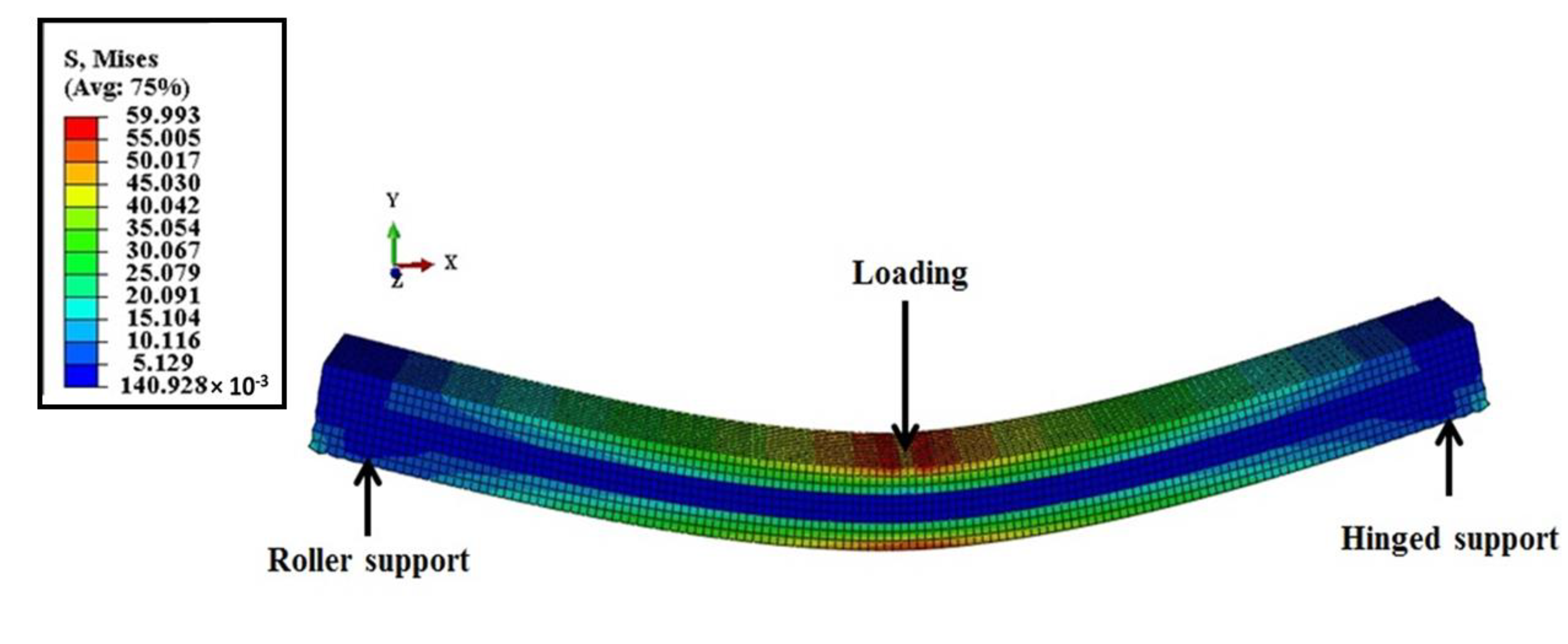
Loading and Boundary Conditions

The load was applied on the top layer surface in a 30 by 12 cm2 area in the center of the beam length in the modeling of the samples, just as it was in the experimental tests. One hardpoint was modeled and connected in the center of the loading surface to apply the concentrated vertical forces in this location. Then the force was input into the hardpoint. Each CLT was modeled with one hinged or pin support and one roller support at the end of the beam length, the same as the experimental tests. The loading and boundary conditions for each model were identical to those used in the experiments. All models were investigated using a static-general solver.

2.5. Bending and Shear Stress Distribution over the Cross-Section of CLT Panel

The bending and shear stress values over the transformed section of CLT specimens were estimated in order to detect the amount of load-bearing capacity of each layer of CLT under out of plane bending test for various configurations. The total bending and shear distribution values in all layers can determine the whole bending strength of CLT in various configurations. In this research, the bending and shear stress values over the cross-section of samples were estimated according to two methods, firstly based on analytical approach using the maximum experimental values of bending moment and shear force [33], and secondly based on numerical analysis using the parameters listed in Table 1 and using FE method by ABAQUS. The analytical and numerical results of the bending and shear stress distribution over the cross-section of CLT were compared with each other.

3. Results and Discussion

3.1. Experimental Bending Test Results

3.1.1. Force–Displacement Response

The results of experimental load-displacement curves of the various configuration of the CLT samples in the major and minor axes are shown in Figure 2. Each graph is a representative sample of each group listed in Table 2. As shown in Figure 2, the CLT specimens had a higher load-bearing capacity in the major axis in comparison with those in the minor axis. The maximum load-bearing capacities in the major direction were recorded in the 0/30/0, 0/45/0, and 0/90/0 configurations, respectively. Furthermore, CLTs with the arrangements of 0/30/0 and 0/45/0 did not exhibit a brittle failure behavior. However, the arrangement of 0/90/0 showed brittle failure after maximum loading and failed immediately. The reason for this behavior was attributed to the low natural resistance of wood in the middle cross-layer of CLT due to the fibers’ orientation. Similarly, Bahmanzad et al. (2020) in their study reported that CLTs with 90° cross layer had lower failure loads than those of 30° and 45° [34]. Besides, CLTs orientated at 45/0/45 arrangement indicated higher load-bearing capacity compared with those orientated at 45/45/45. However, in the minor axis, the CLTs orientated at the 90/0/90 showed lower bending stiffness than those orientated at the 45/45/45. The least load-bearing capacity in the minor axis was observed at CLTs with a 90/60/90 arrangement. In general, the 0/30/0, 0/45/0, and 0/90/0 arrangements showed lower deformation with a higher load-bearing capacity than the other arrangements.

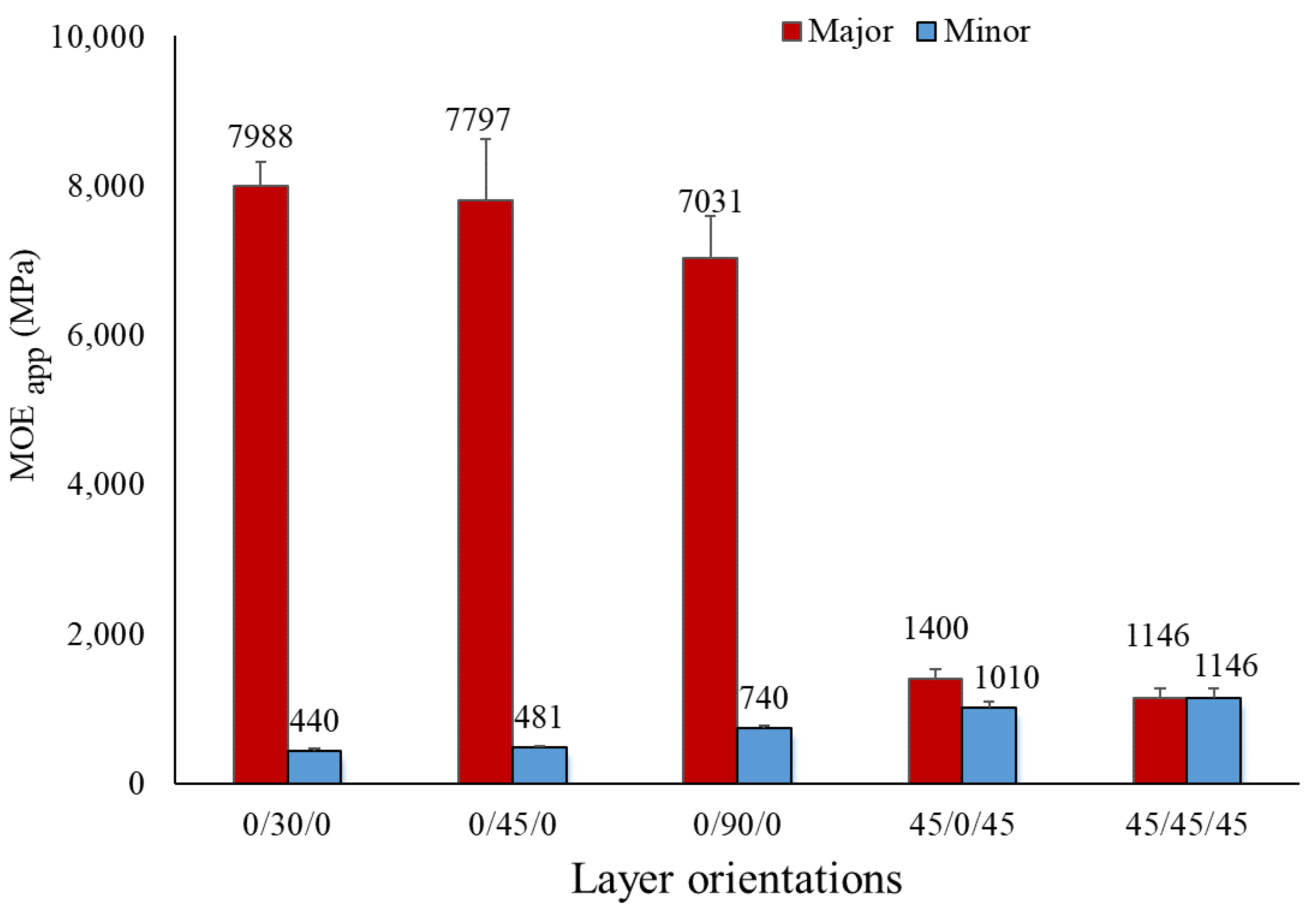
3.1.2. Apparent Modulus of Elasticity (MOEapp)

The results of the experimental MOEapp of CLTs manufactured in various configurations in major and minor axes are presented in Figure 3. The highest value of MOEapp of CLT panels was observed at the 0/30/0 configuration, followed by 0/45/0, 0/90/0, 45/0/45, and 45/45/45. The results showed that with alteration of middle layer angle from 30° to 45° or 30° to 90°, the average MOEapp value decreased by 2.4% and 13.6%, respectively, while the maximum value of MOEapp in the minor axis of CLT was obtained at the 45/45/45 arrangement, followed by 45/90/45, 90/0/90, 90/45/90, and 90/60/90. In the minor axis, the CLTs with a surface layer angle of 45° presented higher MOEapp than those with a 90° angle as the maximum value of MOEapp was measured at about 1150 MPa for 45/45/45 configuration. This decreasing trend of MOEapp values was due to the lower stiffness of wood in the middle layer at a greater inclination angle from the beam length axis under bending loading. As a result, the higher the fiber inclination angle from the beam length axis, the lower the bending strength of CLTs. In other words, the MOEapp values of CLT were highly affected when the middle layer angle altered from 30° to 45° or 90°. The results showed that in the major axis, the MOEapp values of specimens were more dependent on the changing angle of surface layers rather than the middle layer. The lowest MOEapp values of CLTs in the major axis were seen at the orientations of 45/0/45 and 45/45/45. Based on the results, the average MOEapp value of CLTs with 45/0/45 orientation was calculated 21% higher than that with 45/45/45 orientation. In addition, the average value of MOEapp of CLTs with 0/90/0 configuration was 511% greater than that with 45/45/45. As a general rule, the higher the total sum of the fiber inclination angle of all layers of the CLT panel, the lower the stiffness of the CLT panel in the minor and major axes.

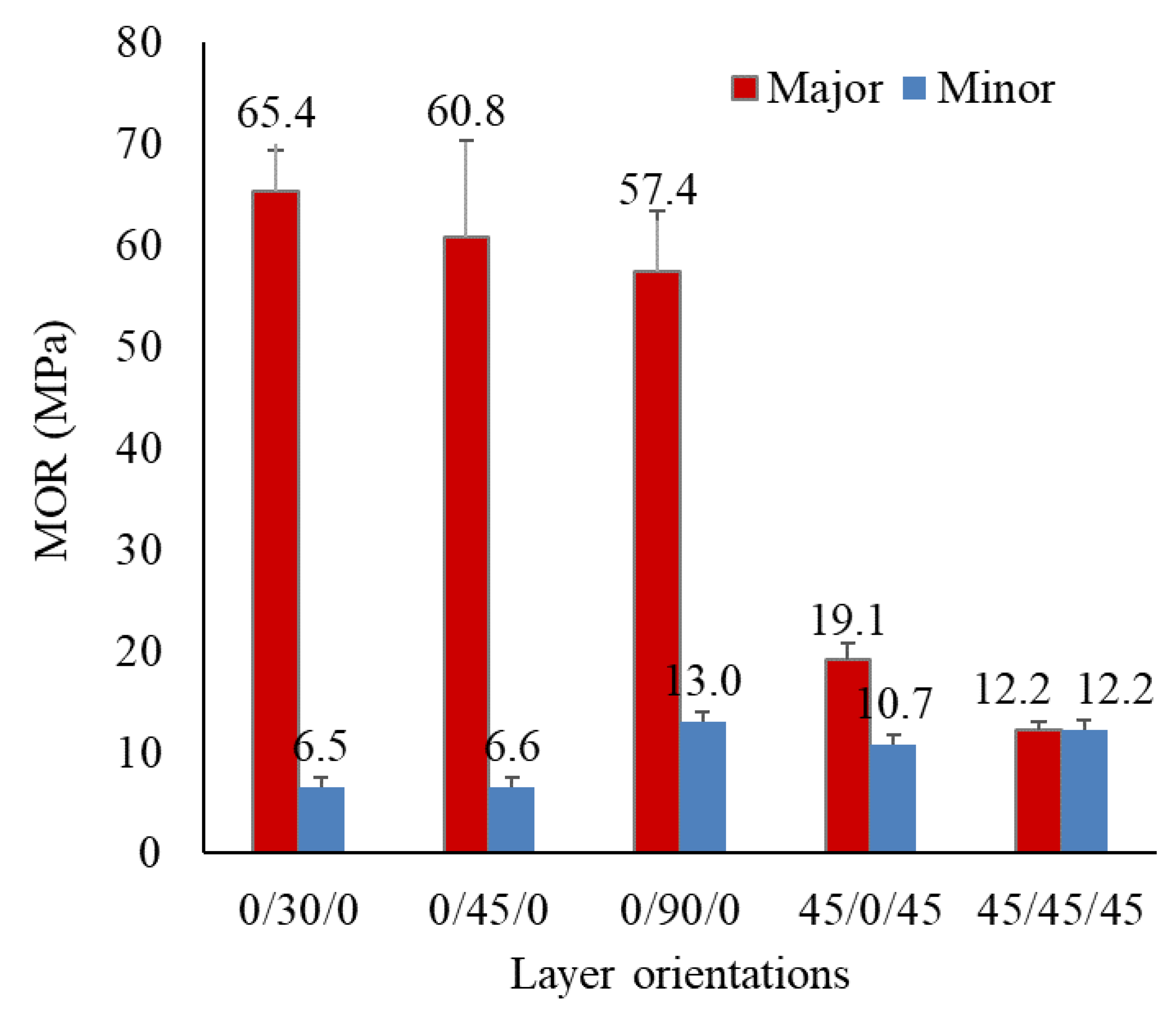
3.1.3. Modulus of Rupture (MOR) of CLT

The averages of the MOR values in major and minor axes of CLTs are illustrated in Figure 4. The value of MOR decreased by 13.2% when the middle layer angle of CLT was changed from 30° (0/30/0) to 90° (0/90/0). CLTs with 45/0/45 and 45/45/45 arrangements had lower MOR values than CLTs with 0/30/0, 0/45/0, and 0/90/0 arrangements. However, the average MOR values of CLTs with 45/0/45 arrangement was 58.3% higher than that with 45/45/45 arrangement. Furthermore, in the minor axis, the maximum average of MOR values was achieved in the 90/0/90 arrangement, followed by 45/45/45 and 45/90/45. In the minor axis, when the middle layer of CLT was orientated at a 0° angle, the CLT panel resisted more bending load; therefore, the maximum average of MOR values in the minor axis was achieved in the 90/0/90 arrangement. Besides, CLTs with 90/60/90 and 90/45/90 arrangements presented lower MOR than the other arrangements due to the intrinsic lower strength of wood at a fiber inclination angle equal to 90° as surface layers, and 45° and 60° as middle layers. Generally, the layer angle in the manufacturing process of CLT plays a key role in determining the final strength of CLTs subjected to bending loading. Naturally, wood exhibits its maximum strength when the fiber’s inclination angle with respect to the length axis is zero while it shows its own lowest strength at the angle of 90°. Thus, in the major axis, surface layers of CLT could resist the highest bending load. According to this reason, the maximum value of MOEapp and MOR in the major axis were obtained in 0/30/0, 0/45/0, and 0/90/0 arrangements, respectively (Figure 3 and Figure 4).

3.1.4. Relationship between MOE and MOR of CLTs

The relationship between MOE and MOR values in various orientations are illustrated in Figure 5. The graph shows a same trend for both MOE and MOR of specimens. Based on the graph, the values of MOE and MOR showed a gradual decreasing trend from 0/30/0 orientation to 0/90/0, then the trend of values plummeted towards 0/90/0. Afterwards, it continued with an almost steady trend to the end orientation.

3.1.5. Finding the Optimal CLT Construction Based on Mechanical Properties

To find the optimal CLT construction in the various orientations, the average MOE and MOR specimens were calculated based on the following Equations
M O E A v e r a g e = M O E m a j o r + M O E m i n o r 2
M O R A v e r a g e = M O R m a j o r + M O R m i n o r 2
Table 4 indicates the average values of MOE and MOR of CLT. According to the results, the maximum averages for both MOE and MOR values were 4214 MPa and 36 MPa, respectively, calculated for CLTs with 0/30/0 orientation. The values of MOE and MOR in 0/30/0 CLTs were 1.8% and 6.8% greater than those of 0/45/0 CLTs, and 8.45% and 2.27% greater than those of 0/90/0, respectively. Furthermore, the CLTs with orientation 0/45/0 showed 6.5 % higher average value of MOE compared to those ones with 0/90/0 orientation, while the average value of MOR of CLTs with 0/90/0 was 4.45% greater than those with 0/45/0 orientation. Moreover, the minimum value of MOE and MOR was 12.2 MPa calculated for 45/45/45 CLTs. In fact, based on MOE factor, the optimal construction of CLT was in 0/30/0, 0/45,0, and 0/90/0 orientations, while according to MOR factor the optimal construction of CLTs was in 0/30/0, 0/90,0, and 0/45/0, respectively. Hence, based on both MOE and MOR values, the optimal CLT was constructed in 0/30/0 orientation.

3.1.6. Failure Modes of CLTs

The most common failure modes of CLTs at different layer arrangements are illustrated in Figure 6 During the experimental test, the crack initiation in all specimens first occurred in wood layers rather than glue line even though the crack propagated in some specimens through the glue line (Figure 6a). In the major axis of 0/30/0, 0/45/0, and 0/90/0 arrangements, the dominant mixed failure modes of specimens were rolling shear failure in the middle layer, delamination failure between layers, and tension failure in the bottommost layer (Figure 6a,c). During the experimental testing of CLT with a 0/90/0 arrangement, first, the rolling shear mode was observed in the middle layer, then the crack propagated through the beam length as delamination mode. Afterward, the tensile failure mode occurred in the bottommost layer. However, in 45/0/45 and 90/0/90 arrangements, the dominant failure mode was tensile in both the bottommost and middle layers (Figure 6c,d). As shown in Figure 6c,d, firstly, the tensile mode occurred at the bottommost layer, next at the middle layer, and finally, the tensile crack propagated in the middle layer through the beam length. Likewise, in 90/60/90, and 90/45/90 configurations, the tensile was the dominant failure mode in both bottommost and middle layers (Figure 6b,d). For CLTs with a 45/45/45 arrangement, the combination of tensile failure and shear crack was detected in the middle layer of CLT (Figure 6d). The type of failure modes of CLT in each configuration are given in Table 5. Several investigations [12,13,14,18,23,25,35] have also reported that the common critical failure mode in the major axis of CLT panel under out-of-plane bending loading was rolling shear of cross-layer because of the low value of shear and rolling shear modulus in radial-tangential (RT) plane of wood. Hematabadi et al. (2020) also reported the tensile mode as a dominant failure mode in the minor axis of regular CLT with the 90/0/90 layer arrangement [10].

3.2. Analytical and Numerical Bending and Shear Stress Distribution of CLT

3.2.1. Bending Stress Distribution of CLT

The bending and shear stress values of CLTs in various arrangements were calculated by the analytical method using the transformed section approach [33], and the numerical method through FEM by ABAQUS software [31]. In order to compute and compare the maximum values of stress distributions by FE and analytical methods, all the orientations were modeled under the same load of 1000 N. Figure 7 is a sample of the FE model of CLT that indicates the deformation and stress values of the CLT panel under the out-of-plane bending loading. The bending and shear stress values presented by FEM matched those values calculated by the analytical method (Figure 8 and Figure 9). The results confirmed that when the fibers’ inclination angle of the surface layers of the beam was 0°, the maximum bending stress occurred at the topmost and bottommost points of the surface layers rather than the middle layer (Figure 8). Actually, the surface layers played an important role in bending stress. Moreover, the trend of bending stress distribution in arrangements 0/30/0, 0/45/0, and 0/90/0 was the same, and the middle layer tolerated the least bending stress. Whilst altering the fibers’ inclination angle in the surface layers of the CLT panels from 0° to 45° and 90° and keeping the middle layer at 0°, the trend of bending stress distribution changed. As shown in Figure 8, the maximum bending stress occurred in the middle layer of CLT panels in orientations of 45/0/45 and 90/0/90, and the surface layers of these orientations tolerated the lowest bending stresses. Under equal bending loading (1000 N), the maximum bending stress in the middle layer in arrangement 90/0/90 was nearly 50% greater than that in 45/0/45 arrangement. Furthermore, the middle layer in the 90/0/90 arrangement tolerated a bending stress of roughly 24 MPa, according to analytical and FE approaches. The surface layers, on the other hand, could only withstand bending stress of about 3.35 MPa. Moreover, the bending stress distribution in 45/45/45 layers arrangement was different from that of the other orientations. According to analytical and FE methods, the bending stress distribution across the thickness of the beam was linear in this orientation, and all three layers were equally responsible for bearing the bending loads.

3.2.2. Shear Stress Distribution of CLT

The shear stress values of CLTs computed in XY plane direction by analytical and FE methods are presented in Figure 9. In all specimens, the shear stress values predicted by the FEM concurred well with those calculated by the analytical method. In the maximum difference, in CLTs with a 90/45/90 arrangement, the shear stress value predicted by the FEM was 14.5% higher than that of the analytical approach. In each arrangement, the shear stress trend started from zero at the upmost and bottommost layers, then reached its highest value in the center of the middle layer (neutral line). However, the increasing slope of shear stress values in arrangements of 0/30/0, 0/45/0, and 0/90/0 was slower than other orientations. In fact, the shear stress value was almost equal throughout the thickness of the middle layer in arrangements of 0/30/0, 0/45/0, and 0/90/0. In other orientations, the maximum shear stress value occurred significantly with a sharp slope in the center of the middle layer of CLTs. Moreover, both FE and analytical methods indicated that under the equal bending loading (1000 N), the middle layer of CLT panels in arrangements 0/30/0, 0/45/0, and 0/90/0 tolerated the lower shear stress than that in other orientations. This behavior of shear distribution can be due to the smaller inclination angle of surface layers from the length axis of the beam. Wood inherently exhibited its maximum strength under bending load when there is no inclination angle of fiber with respect to its longitudinal axis. In other words, the smaller the fibers’ inclination angle of the layer, the higher the strength of the CLT panel under bending. This can be the reason why CLTs with a 0/30/0 arrangement showed higher load-bearing capacity in experimental tests. Additionally, under an equal load, the orientations 90/0/90, 45/0/45, and 90/45/90, respectively, tolerated the maximum shear stress values in their middle layer compared to the other orientations. The maximum difference of the shear stress value in the middle layer was observed between CLT with orientation 90/0/90 and 0/90/0, which was 100% greater in 90/0/90.

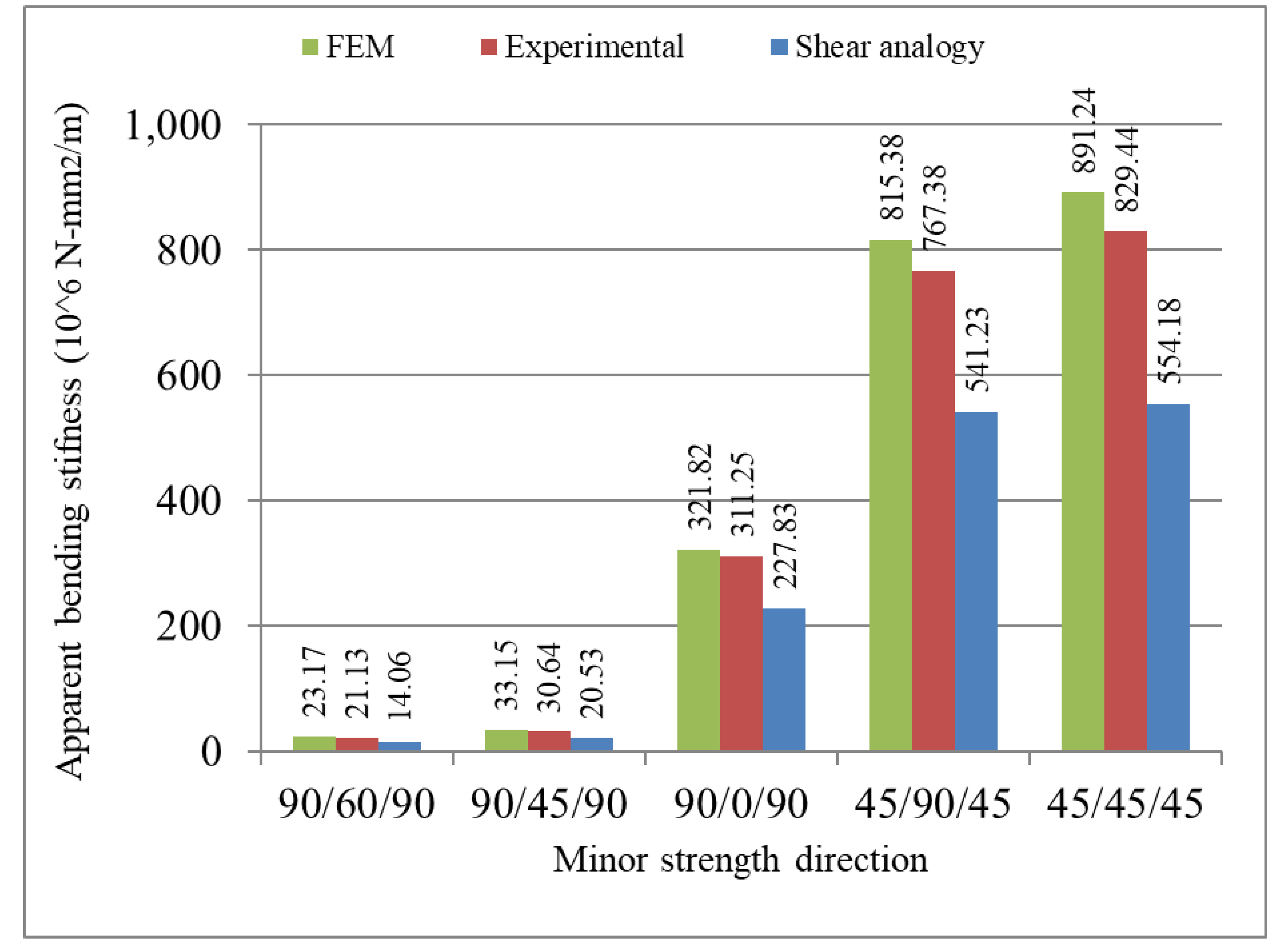
3.3. Apparent Bending Stiffness (EIapp)

Apparent bending stiffness (EIapp) value of CLT panels was calculated experimentally (EIapp,exp) using Equation (2) according to the ASTM D198 standard, theoretically according to shear analogy approach (EIapp,shear) using Equation (7), and numerically (EIapp,fem) using load/deflection parameters computed from modeling of CLTs by Abaqus software and using Equation (2).
The comparison of EIapp values of CLT using experimental, shear analogy, and FEM in various configurations were depicted in Figure 10 and Figure 11. According to the three methods, the major axis of CLT with a 0/30/0 configuration had the highest bending stiffness value, followed by 0/45/0, 0/90/0, 45/0/45, and 45/45/45. This behavior of CLTs was in agreement with the apparent bending stiffness found by Bahmanzad et al. [34]. They reported that the apparent bending stiffness value of CLT with a 30° cross layer was higher than those with 45° and 90°. In contrast, the 45/45/45, 45/90/45, 90/0/90, 90/45/90, and 90/60/90 configurations in the minor axis showed the highest value of bending stiffness, respectively. The natural stiffness of wood layers at different fibers’ inclination angles affects the whole bending stiffness of CLT panels. Consequently, the panels with a higher fibers’ inclination angle along the beam showed lower bending stiffness. Comparing the experimental and shear analogy methods for the arrangements of 0/30/0, 0/45/0, 0/90/0, 45/0/45, 45/45/45, 90/60/90, 90/45/90, 90/0/90, and 45/90/45, the average EIapp,exp values were, respectively, 21.38%, 20.74%, 23.34%, 20.03%, 33.18%, 33.45%, 33%, 26%, and 29.4% greater than EIapp,shear value. Crovellaet al. [36] investigated the EIapp values by the experimental test and shear analogy method for CLT manufactured from Eastern White Pine, Red Maple, and White Ash. They revealed that the shear analogy approach predicted the EIapp value of the softwood and hardwood CLTs by 5% and 25% less than that of the experimental tests. In this research, there was a good agreement between the experimental tests and the FE method for calculating the EIapp of CLTs. Comparing the experimental and FEM results, the EIapp,exp values were 2.17%, 4.16%, 3.4, 6.57%, 6.93%, 8.81%, 7.57%, 3.28%, and 5.88%, less than EIapp,fem, respectively, for the arrangements of 0/30/0, 0/45/0, 0/90/0, 45/0/45, 45/45/45, 90/60/90, 90/45/90, 90/0/90, and 45/90/45.

4. Conclusions

The bending properties of three-layer CLT manufactured from poplar (Populus deltoides L.) with different layer configurations were investigated using experimental, theoretical, and numerical methods. The results of this study are as follows:
  • Based on both average MOE and MOR values in both major and minor direction, the optimal CLT was constructed in 0/30/0 orientation. However, based on average MOE values, the optimal construction of CLT was in 0/30/0, 0/45,0, and 0/90/0 orientations, while according to average MOR, the optimal construction of CLTs was in 0/30/0, 0/90,0, and 0/45/0, respectively. Moreover, the 45/45/45 orientation indicated the least CLT construction.
  • The dominant failure modes in the major axis were rolling shear and delamination, however, the dominant failure modes in the minor axis were observed as tensile failures and cracks.
  • Under an equal loading, both FE and theoretical methods indicated that the maximum bending and shear stress values occurred in middle layers of CLT panels with orientations 90/0/90 and 45/0/45, respectively.
  • Comparing the experimental, shear analogy, and FE methods, the EIapp,exp value in all arrangements was at least 20% greater than EIapp,shear value of CLTs. However, the EIapp,fem value was maximally 8% greater than the EIapp,exp value.

Author Contributions

Conceptualization, A.R.H. and H.H.; Methodology, A.R.H. and H.H.; Software, H.H.; Validation, H.H.; Formal Analysis, A.R.H. and H.H.; Investigation, A.R.H. and H.H.; Resources, A.R.H. and H.H.; Data Curation, A.R.H. and H.H.; Writing – Original Draft Preparation, A.R.H. and H.H.; Writing – Review & Editing, A.R.H. and H.H.; Visualization, A.R.H. and H.H.; Supervision, A.R.H. and H.H.; Project Administration, A.R.H. and H.H.; Funding Acquisition, A.R.H. and H.H. All authors have read and agreed to the published version of the manuscript.

Funding

This research received no external funding.

Institutional Review Board Statement

Not applicable.

Data Availability Statement

Data sharing is not applicable.

Conflicts of Interest

The authors declare no conflict of interest.

References

  1. ANSI/APA PRG 320; Standards for Performance-Rated Cross-Laminated Timber. ANSI/APA: Tacoma, WA, USA, 2012.
  2. Gagnon, S.; Pirvu, C. CLT Handbook: Cross-Laminated Timber; FPInnovations: Pointe-Claire, QC, Canada, 2011. [Google Scholar]
  3. Hassan, O.A.; Öberg, F.; Gezelius, E. Cross-laminated timber flooring and concrete slab flooring: A comparative study of structural design, economic and environmental consequences. J. Build. Eng. 2019, 26, 100881. [Google Scholar] [CrossRef]
  4. Robertson, A.B.; Lam, F.C.; Cole, R.J. A comparative cradle-to-gate life cycle assessment of mid-rise office building construction alternatives: Laminated timber or reinforced concrete. Buildings 2012, 2, 245–270. [Google Scholar] [CrossRef]
  5. Kramer, A.; Barbosa, A.R.; Sinha, A. Viability of hybrid poplar in ANSI approved cross-laminated timber applications. J. Mater. Civ. Eng. 2014, 26, 06014009. [Google Scholar] [CrossRef]
  6. Wang, Z.; Fu, H.; Chui, Y.-h.; Gong, M. Feasibility of using poplar as cross layer to fabricate cross-laminated timber. In Proceedings of the World Conference on Timber Engineering, Quebec City, QC, Canada, 10–14 August 2014. [Google Scholar]
  7. Wang, Z.; Gong, M.; Chui, Y.-H. Mechanical properties of laminated strand lumber and hybrid cross-laminated timber. Constr. Build. Mater. 2015, 101, 622–627. [Google Scholar] [CrossRef]
  8. Wang, Z.; Fu, H.; Gong, M.; Luo, J.; Dong, W.; Wang, T.; Chui, Y.H. Planar shear and bending properties of hybrid CLT fabricated with lumber and LVL. Constr. Build. Mater. 2017, 151, 172–177. [Google Scholar] [CrossRef]
  9. Davids, W.G.; Willey, N.; Lopez-Anido, R.; Shaler, S.; Gardner, D.; Edgar, R.; Tajvidi, M. Structural performance of hybrid SPFs-LSL cross-laminated timber panels. Constr. Build. Mater. 2017, 149, 156–163. [Google Scholar] [CrossRef]
  10. Hematabadi, H.; Madhoushi, M.; Khazaeyan, A.; Ebrahimi, G.; Hindman, D.; Loferski, J. Bending and shear properties of cross-laminated timber panels made of poplar (Populus alba). Constr. Build. Mater. 2020, 265, 120326. [Google Scholar] [CrossRef]
  11. Zhou, Q.; Gong, M.; Chui, Y.H.; Mohammad, M. Measurement of rolling shear modulus and strength of cross laminated timber fabricated with black spruce. Constr. Build. Mater. 2014, 64, 379–386. [Google Scholar] [CrossRef]
  12. Lu, Y.; Xie, W.; Wang, Z.; Gao, Z. Shear stress and interlaminar shear strength tests of cross-laminated timber beams. BioResources 2018, 13, 5343–5359. [Google Scholar]
  13. Pang, S.-J.; Jeong, G.Y. Effects of combinations of lamina grade and thickness, and span-to-depth ratios on bending properties of cross-laminated timber (CLT) floor. Constr. Build. Mater. 2019, 222, 142–151. [Google Scholar] [CrossRef]
  14. Pangh, H.; Hosseinabadi, H.Z.; Kotlarewski, N.; Moradpour, P.; Lee, M.; Nolan, G. Flexural performance of cross-laminated timber constructed from fibre-managed plantation eucalyptus. Constr. Build. Mater. 2019, 208, 535–542. [Google Scholar] [CrossRef]
  15. ANSI/APA PRG 320; Standard for Performance-Rated Cross-Laminated Timber. ANSI/APA: Tacoma, WA, USA, 2019.
  16. Corpataux, L.; Okuda, S.; Kua, H.W. Panel and plate properties of Cross-laminated timber (CLT) with tropical fast-growing timber species in compliance with Eurocode 5. Constr. Build. Mater. 2020, 261, 119672. [Google Scholar] [CrossRef]
  17. Hematabadi, H.; Hindman, D.P. Comparison of test methodologies for computing bending and shear stiffness of cross-laminated timber. J. Test. Eval. 2020, 49, 1533–1549. [Google Scholar] [CrossRef]
  18. Buck, D.; Wang, X.A.; Hagman, O.; Gustafsson, A. Bending properties of cross laminated timber (CLT) with a 45 alternating layer configuration. BioResources 2016, 11, 4633–4644. [Google Scholar] [CrossRef]
  19. Fellmoser, P.; Blass, H.J. Influence of rolling shear modulus on strength and stiffness of structural bonded timber elements. In Proceedings of the CIB-W18 Meeting, Edinburgh, UK, August 2004. [Google Scholar]
  20. Niederwestberg, J.; Zhou, J.; Chui, Y.-H. Mechanical properties of innovative, multi-layer composite laminated panels. Buildings 2018, 8, 142. [Google Scholar] [CrossRef] [Green Version]
  21. Li, M.; Füssl, J.; Lukacevic, M.; Martin, C.M.; Eberhardsteiner, J. Bending strength predictions of cross-laminated timber plates subjected to concentrated loading using 3D finite-element-based limit analysis approaches. Compos. Struct. 2019, 220, 912–925. [Google Scholar] [CrossRef]
  22. Mahamid, M.; Torra-Bilal, I. Analysis and design of cross-laminated timber mats. Pract. Period. Struct. Des. Constr. 2019, 24, 04018031. [Google Scholar] [CrossRef]
  23. He, M.; Sun, X.; Li, Z. Bending and compressive properties of cross-laminated timber (CLT) panels made from Canadian hemlock. Constr. Build. Mater. 2018, 185, 175–183. [Google Scholar] [CrossRef]
  24. Navaratnam, S.; Christopher, P.; Ngo, T.; Le, T. Bending and shear performance of Australian Radiata pine cross-laminated timber. Constr. Build. Mater. 2020, 232, 117215. [Google Scholar] [CrossRef]
  25. Li, X.; Ashraf, M.; Subhani, M.; Kremer, P.; Kafle, B.; Ghabraie, K. Experimental and numerical study on bending properties of heterogeneous lamella layups in cross laminated timber using Australian Radiata Pine. Constr. Build. Mater. 2020, 247, 118525. [Google Scholar] [CrossRef]
  26. Xiao, Y.; Cai, H.; Dong, S. A pilot study on cross-laminated bamboo and timber beams. J. Struct. Eng. 2021, 147, 06021002. [Google Scholar] [CrossRef]
  27. Hematabadi, H.; Madhoushi, M.; Khazaeian, A.; Ebrahimi, G. Structural performance of hybrid Poplar-Beech cross-laminated-timber (CLT). J. Build. Eng. 2021, 44, 102959. [Google Scholar] [CrossRef]
  28. Aicher, S.; Hirsch, M.; Christian, Z. Hybrid cross-laminated timber plates with beech wood cross-layers. Constr. Build. Mater. 2016, 124, 1007–1018. [Google Scholar] [CrossRef]
  29. Sikora, K.S.; McPolin, D.O.; Harte, A.M. Effects of the thickness of cross-laminated timber (CLT) panels made from Irish Sitka spruce on mechanical performance in bending and shear. Constr. Build. Mater. 2016, 116, 141–150. [Google Scholar] [CrossRef] [Green Version]
  30. ASTM D198; Standard Test Methods of Static Tests of Lumber in Structural Sizes. ASTM International: West Conshohocken, PA, USA, 2008.
  31. Dassault Systèmes, D. Abaqus Analysis User’s Guide; Technical Report Abaqus 6.14 Documentation, Simulia Corp: Johnston, RI, USA, 2016. [Google Scholar]
  32. Hankinson, R. Investigation of crushing strength of spruce at varying angles of grain. Air Serv. Inf. Circ. 1921, 3, 130. [Google Scholar]
  33. Beer, F.; Johnston, E., Jr.; Dewolf, J.; Mazurek, D. Mechanics of Materials, 6th ed.; Wiley: New York, NY, USA, 2010. [Google Scholar]
  34. Bahmanzad, A.; Clouston, P.; Arwade, S.; Schreyer, A. Shear properties of eastern hemlock with respect to fiber orientation for use in cross laminated timber. J. Mater. Civ. Eng. 2020, 32, 04020165. [Google Scholar] [CrossRef]
  35. Liao, Y.; Tu, D.; Zhou, J.; Zhou, H.; Yun, H.; Gu, J.; Hu, C. Feasibility of manufacturing cross-laminated timber using fast-grown small diameter eucalyptus lumbers. Constr. Build. Mater. 2017, 132, 508–515. [Google Scholar] [CrossRef]
  36. Crovella, P.; Smith, W.; Bartczak, J. Experimental verification of shear analogy approach to predict bending stiffness for softwood and hardwood cross-laminated timber panels. Constr. Build. Mater. 2019, 229, 116895. [Google Scholar] [CrossRef]
Figure 1. A schematic of loading conditions of specimens under experimental bending test.
Buildings 12 00608 g001
Figure 2. Force–displacement response in each group for bending test samples.
Buildings 12 00608 g002
Figure 3. Modulus of elasticity (MOEapp) of CLTs in both major and minor axes.
Buildings 12 00608 g003
Figure 4. Modulus of rupture (MOR) of CLTs in both major and minor axes.
Buildings 12 00608 g004
Figure 5. Relationship of MOE and MOR in various orientations.
Buildings 12 00608 g005
Figure 6. The types of failure modes of CLTs in the various arrangement (ad) under out-of-plane bending test.
Buildings 12 00608 g006
Figure 7. Deformation and stress distribution in CLT panel using the FEM method.
Buildings 12 00608 g007
Figure 8. The bending stress distribution of CLTs with different arrangements of layers.
Buildings 12 00608 g008
Figure 9. The shear stress distribution of CLTs with different arrangements of layers.
Buildings 12 00608 g009
Figure 10. Comparison of apparent bending stiffness (EIapp) values estimated by the experimental test, shear analogy, and FEM methods in major axis of CLT.
Buildings 12 00608 g010
Figure 11. Comparison of apparent bending stiffness (EIapp) values using the experimental test, shear analogy, and FEM approaches in minor axis of CLT.
Buildings 12 00608 g011
Table 1. Elastic parameters of poplar species at 12% moisture content [10].
Density (g/cm3)EL (MPa)ER (MPa)ET (MPa)νLRνLTνRTGLR (MPa)GLT (MPa)GRT (MPa)
0.3889007394180.3440.420.875676463134
Table 2. CLT panels configurations used for the bending test.
Group NameLayer Arrangement in Major Axis (Degree)Group NameLayer Arrangement in Minor Axis (Degree)
A0/30/0F90/60/90
B0/45/0G90/45/90
C0/90/0H90/0/90
D45/0/45I45/90/45
E45/45/45E45/45/45
Table 3. Modulus of elasticity and modulus of rigidity of the poplar wood at various degrees in accordance with shear analogy approach using Hannkinson’s Equation.
Grain Axis θ (Degree)030456090
Modulus of Elasticity (MPa)89001079.9574.8391.6297
Modulus of rigidity (MPa)556.25171.15101.1471.7855.62
Table 4. The average values of MOE and MOR of CLT.
Orientatios MOE MajorMOE
Minor
Average MOEMOR MajorMOR
Minor
Average MOR
0/30/07988440421465.56.536
0/45/07797481413960.86.633.7
0/90/070317403885.557.41335.2
45/0/4514001010120519.110.714.9
45/45/4511461146114612.212.212.2
Table 5. The types of failure modes of CLTs in various orientations.
Layers Orientations (Major Axis)Failure Modes
in Major Axis
Layers Orientations (Minor Axis)Failure Modes
in Minor Axis
0/30/0Tensile and Delamination90/60/90Tensile
0/45/0Tensile and Delamination90/45/90Tensile
0/90/0Tensile and Delamination90/0/90Tensile
45/0/45Tensile45/90/45Tensile and Delamination
45/45/45Tensile, Shear and Delamination45/45/45Tensile, Shear and Delamination
Publisher’s Note: MDPI stays neutral with regard to jurisdictional claims in published maps and institutional affiliations.

