Review

Climate-Adaptive Façades with an Air Chamber

by
Irina Leonidovna Vasileva
1,*,
Darya Viktorovna Nemova
1,
Nikolai Ivanovich Vatin
2,
Roman Sergeevich Fediuk
3 and
Maria Iurevna Karelina
4
1
Peter the Great St. Petersburg Polytechnic University, 195251 St. Petersburg, Russia
2
People’s Friendship University of Russia, 117198 Moscow, Russia
3
Far Eastern Federal University, 690950 Vladivostok, Russia
4
Moscow Automobile and Road Construction State Technical University, 125319 Moscow, Russia
*
Author to whom correspondence should be addressed.
Buildings 2022, 12(3), 366; https://doi.org/10.3390/buildings12030366
Submission received: 7 February 2022 / Revised: 1 March 2022 / Accepted: 14 March 2022 / Published: 16 March 2022
(This article belongs to the Section Building Energy, Physics, Environment, and Systems)

Abstract

:
The development of energy-efficient technologies at all stages of a building’s life cycle is essential to achieving sustainable development goals. The object of the study is climate-adaptive façade structures with air gaps in the form of a Trombe wall and a double-skin façade. Cases using phase-change materials (PCM) and photovoltaic modules (PV) in climate-adaptive structures are analyzed separately. The research method is aimed to review and analyze the energy-saving potential from integrating the Trombe wall or double-skin façade in buildings. The work systematizes full-scale, physical, and mathematical experiments. Articles from Scopus and Web of Science systems from 2001 to 2022 inclusive were subject to consideration. The article presents a statistical analysis given by the scientific community on the current topic’s dynamics. The study’s significance is characterized by a lack of knowledge on the behavior of the mentioned façade systems in various climate zones and for different buildings types. The results have shown that comprehensive studies on the investigated systems are significant and can serve for further designs and energy efficiency improvements. For the first time, a scientometric analysis of articles on the topic “Climate-adaptive façades” was compiled.

1. Introduction

Energy saving is an increasing priority in the policies of many nations. It is one of the sustainable development goals [1,2]. The reason behind that is the depletion of essential energy resources, the rising price of their extraction, and the global environmental problems associated with this process [3].
One of the most active consumers of energy is the construction sector. The most acute problem of energy saving concerns the longest stage of the object life cycle, building operation [4,5,6,7]. This stage requires a constant inflow of energy resources consumed for heating, ventilation, hot water, premises’ lighting, and different equipment operations [8]. Energy efficiency issues need to already be considered at the design stage. The study [9] presented in this article showed that choosing a structural system and its elements could significantly affect the saving of energy resources, cost, and the impact of a building on the environment.
Various thermal insulation materials are actively considered at the project development stage [10,11,12,13,14]. However, it is not economically feasible to insulate walls more than a particular value, and in buildings with translucent façades, insulation is not appropriate for aesthetic reasons. Consequently, it is necessary to look for efficient alternative systems. One of the most promising trends in this field is the change to kinetic architecture and the development of climate-adaptive façade structures [15,16,17,18]. Such systems can partially or entirely change the mode of operation depending on the respective climatic conditions, the time of year, and even temperature variations during the day [19,20,21,22,23,24,25].
Façade structures with an inner air layer or air chamber are actively developing among climate-responsive structures. There are different options for using the air layer in building envelopes: ventilated roofs [26,27,28], ventilated windows [29,30,31,32,33], walls [34,35,36,37].
Scientists pay special attention to façade structures with an air layer. They can be divided into closed and non-closed air cavity façades in terms of their modes of operation. Façades with non-enclosed air cavities can be divided into natural and forced-air façades [38,39]. When the air in the cavity moves in natural ventilation mode, the driving force is due to convection, i.e., differences in air temperatures (density differences) at the inlet and outlet of the air duct. In mechanically-ventilated façade systems, special ventilation equipment is usually used to circulate the airflow.
Creating climate-adaptive energy-efficient structures is also facilitated by using innovative materials, such as phase-change materials (PCM). The energy-saving potential was considered using the example of a three-story office building in China [40]. It was modeled under different climatic conditions. The energy-saving potential of Shenyang, located in a harsh cold climate, was the most sustainable. In terms of energy saving, PCM integration is also rational in Zhengzhou (located in a cold region) and Changsha (hot summer and cold winter). In Kunming and Hong Kong, the event has no economic benefit. Scientists from Australia investigated the effect of the thickness of the PCM thermal insulation layer on the overall energy efficiency of a building [41]. Increased PCM thickness from 5 mm to 10 mm led to decreased energy demand for cooling and heating by 23% and 12%, respectively.
PCM is actively used in combination with photovoltaic cells (PV). It was calculated that the effect and performance of a photovoltaic panel using PCM increases by more than 2.5%, according to [42].
The purpose of this study is to analyze the operating modes of climate-adaptive façades with air interlayers using a Trombe wall and the double-skin façade and to determine the potential use and suitability of these systems for different structural designs. The work systematizes in situ, physical, and mathematical experiments.
Articles from Scopus and Web of Science systems from 2001 to 2022 inclusive were subject to consideration. The work is based on articles from SciVal Topics “Solar Collectors; Phase Change Materials; Photovoltaic System”, “Trombe Walls; Solar Chimneys; Natural Ventilation”, “Façades; Blinds; Natural Ventilation”, “Phase Change Materials; Heat Storage; Octadecane”, “Zero Energy Buildings; Refurbishment; Renovation”, “Thermal Comfort; Indoor Environmental Quality; Office Buildings”, “Free Convection; Rayleigh Number; Chimney Height”, “Electricity Costs; Photovoltaic System; Solar Energy”. The absence of a topic with the name “Climate-adaptive façades” indicates a need for a scientometric analysis of this topic.
The article is divided into seven sections. Section 1 includes a literature review of the prospective implementation of climate-adaptive façades with an air chamber. Section 2 describes the methods used to achieve the aim of the current study. A classification and a comparative analysis of the studied façade systems are given in Section 3. Section 4 demonstrates the scientometric analysis of the climate-adaptive façades as the main research object. A discussion of the previously achieved results is introduced in Section 5. Recommendations for further studies and conclusions are given in Section 6 and Section 7.

2. Methods

The research work is based on an integrated approach. The following methods were used to fulfill the aim of the study:
  • A literature review of the Trombe wall and the Double-Skin Façade systems for the period 2001 to 2022.
  • Classification, analysis, and data synthesis of the studied façade systems.
  • Creating a new research topic, whose title is “Climate-adaptive façades”.
  • Scientometric assessment of the studied topic “Climate adaptive façades” using SciVal tools and the VosViewer software package.
  • Results comparison and analytical study.

3. Climate-Adaptive Construction

3.1. The Trombe Wall

The depletion of natural resources has sparked interest in renewable energy sources, such as solar energy. Its consideration and application are possible even in undeveloped, remote areas. According to the data given in [43,44], passive solar technology can reduce the annual heating requirement by up to 25%. In order to store solar energy and reduce pollution and greenhouse gas emissions, a construction called the Trombe wall is beginning to be actively used in architecture and construction.
The classic Trombe wall consists of a basic 10–40 cm thick wall (brickwork, concrete, stone), preceded by single or double glazing. The glass surface is set back 2–5 cm from the main masonry, forming an air chamber. For moderate climates, single glazing is sufficient, and for cold climates, double glazing with Low-E must be used [45]. For harsh climates, according to [46,47], the width of the air duct must be significantly larger (29–35 cm).
The Trombe wall is constructed so that it faces south. The core masonry is covered with a dark heat-absorbing material on the outside, which is generally selective and has a high absorption capacity and low emissivity [48,49,50,51]. The idea behind the Trombe wall design is that heat from sunlight passes through the glass, is absorbed by the dark surface, accumulates in the wall, and slowly passes inside the building through the masonry, heating the indoor air through radiative and convective heat transfer. Ventilation holes in the upper and lower parts of the solid wall provide the necessary air circulation [46,52,53].
The wall design originated from the American engineer Edward Morse, who designed it for the first time in 1881. In 1960, the French designer Felix Trombe used the results of Morse’s research, revived the idea, and improved its design and functionality. Since then, the dark glazed wall became known as the “The Trombe wall” [44,54].
The exterior glazing of the Trombe wall is fitted with adjustable dampers and adjustable ventilation openings. In this way, the Trombe wall can be modified and adapted to different climates, purposes, and seasons, as shown in Figure 1 [34].
In winter, it is recommended to keep all dampers and vents closed at night, i.e., use the unventilated mode (Figure 1a). In this way, a layer of air insulation is formed, which retains the heat accumulated during the day.
For winter day mode (Figure 1b), keeping the shutters closed while both vents remain open is recommended to allow air circulation between the room’s interior and the air duct through convection. Air from the room, entering the duct through the lower opening, is heated and returned to the room through the upper slot. If fresh air needs to be admitted, one of the flaps can be opened to allow outside air to enter the duct. The fresh air and room air mixture are heated together and transported through the top vent to the room.
It is advisable to keep the top opening and bottom flap closed during the warm season and the bottom opening and top flap open (Figure 1c). Due to the draught, room air flows from the lower vent to the duct; after heating, the airflow rises and then is discharged into the environment through the upper damper. In this way, excess warm air is drawn in, resulting in a summer cooling effect in the room concerned.
Architects and thermal engineers can design Trombe walls as a system of windows, eaves, and other building design elements to balance solar heat accumulation. For example, an intelligent selection of roof overhangs can help shade the wall and prevent heat build-up at times when heat is not needed.
The Trombe wall design is already used at the Zion National Park Visitor Center in Utah, The United States of America (climate zone according to Köppen is Dsb, Dsc), (Figure 2a). The 1.8 m high wall (total area 68.7 m2) runs the entire length of the south wall below a row of windows and accounts for 44% of the whole south side area. The core masonry is concrete blocks (20 cm) filled with cement mortar and coated with dark paint on the south side. In front of the wall is solid patterned glass and partially conceals the dark color of the wall without compromising transparency due to its good transmittance (Figure 2b) [55,56].
The performance of the Trombe wall is impaired if it is cluttered with furniture on the room side. According to the kitchen furniture’s location, the potential heat generated by the Trombe wall is reduced by more than 40%, as stated by [55].
The energy performance of the Visitor Center building was monitored over two years. The analysis consisted of measuring electrical values, making temperature profiles of the Trombe wall, and creating thermographic images. Figure 3 [55] shows the thermal distribution along the Trombe wall in December. The internal surface temperature is relatively uniform and ranges from 32 to 36 °C (90–96 °F). The maximum temperature is usually reached between 8 p.m. and 9 p.m. The lower temperature of the structure on the far right side of the Trombe wall is due to the shading of this part in the afternoon from the outside [55].
The calculations showed that during a heating period of 151 days, the Trombe wall operated for 149 days. It created an additional load on the heating system for two days, i.e., consumed heat energy. Overall, this structure stored heat and contributed to about 20% of the total heating of the building, i.e., it proved to be energy efficient [55,56].

3.1.1. The Trombe Wall with Nanomaterials

The efficiency of the Trombe wall can be significantly improved by replacing conventional glazing with lightweight polycarbonate panels filled with aerogel nanoporous insulation [56,57,58]. This nano-insulator is translucent. Aerogel has excellent thermal insulation properties because its closed nano-cells contain trapped still air [3].
The aerogel construction was investigated for the first time. There was no established methodology or design guide for determining the rational dimensions of Trombe walls containing aerogel insulation. The authors carried out Parametric modeling to fill this gap in science. During a full-scale seven-day test, peak temperatures of up to 45 °C were observed at the inlet of the duct. Thus, the fresh air inlet of the dwelling was preheated to 30 °C, which provided an internal temperature of 21–22 °C without additional heating. The monitoring results were confirmed with up to 5% of the predictions.
The article [59] investigates the Trombe wall, in which a liquid with carbon nanotubes (CNT-water) is used between the main wall and the glazing. The authors considered this system using computational fluid dynamics (CFD) modeling. The addition of nanoparticles increases the heat transfer rate and flow rate. An increase in the Rayleigh number causes a vertical stratification of the temperature field in the cavity.

3.1.2. The Trombe Wall Using Phase-Change Materials (PCM)

One component of the Trombe wall, solid masonry made of brick or concrete, can be replaced by a phase-change material (PCM) [60,61,62,63,64,65]. Phase-change materials refer to materials that store and release heat energy during melting and freezing (change from one phase to another). When such a material freezes, it releases much power in latent heat or crystallization energy. Conversely, the same amount of energy is absorbed from the environment [44,66]. The classification of phase-change materials and the frequency of their use in different world regions is given in Figure 4a,b [67].
One of the first PCM uses for building structures was considered by L. Bourdeau [68]. Conducting a numerical study, he observed that a 0.15 m thick wall made of concrete could be replaced by a 0.035 m thick wall made of phase-change material (calcium chloride hexahydrate CaCl2∙6H2O) and work similarly. Works [69,70] are based on his conclusions.
In article [71], a computer simulation of the performance of a building with an idealized (no supercooling) solid phase-change material was carried out. A Trombe wall with a phase-change material can surpass the thermal performance of a conventional concrete Trombe wall, which needs to be four times thicker and nine times heavier for equivalent performance.
A team of Japanese researchers led by Onishi [72] conducted a similar study of the heat fluxes of the Trombe wall using a phase-change material. The simulation results indicate the effectiveness of PCM and suggest the possibility of further development of homes using this design for potential low energy consumption. The researchers recommended several further systematic tests to optimize PCM integration walls (detailed investigation of the phase-change point, the proportion of PCM in walls for heat storage and their size, etc.).
As a result of numerical simulations, scientists from Iraq found that a 0.08 m thick warehouse wall made of calcium chloride hexahydrate (CaCl2∙6H2O) maintained a comfortable room temperature with the lowest temperature fluctuations compared to a 0.2 m thick concrete wall and a 0.05 m thick paraffin wall (Table 1) [73].

3.1.3. The Trombe–Michel Wall

The Trombe composite wall, also known as the Trombe–Michel wall [23,31,34,44,58,59,60,61,74,75,76], is a complex construction of the following components: a transparent glass plane, a solid wall, a closed cavity, a ventilated air cavity, and an insulating panel (Figure 5).
The glass surface lets in incident sunlight, the solid masonry wall receives and absorbs some of the sun’s energy, heating it. A kind of greenhouse effect is created in the closed cavity. The masonry wall transfers part of the absorbed energy to the ventilated duct of the building, and then it enters the room through convection. The heat in the room can be controlled by influencing the airflow in the duct through the ventilation openings. The thermal resistance of the wall is higher than that of a classic Trombe wall due to thermal insulation and a closed air cavity.
The Trombe composite wall with phase-change materials’ combined behavior (Figure 6) is given in [70]. Instead of classic solid masonry made of brick or concrete, they used “bricks” made of phase-change materials. The PCMs were packaged in a polyolefin shell in a parallelepiped shape (21 cm × 14 cm × 2.5 cm). A mixture of hydrated salts water + calcium chloride (CaCl2) + potassium chlorides (KCl) + additives) was used as the PCM. The wall consisted of nine bricks arranged 3 × 3 in a wooden frame. There were black-coated metal plates on the outside used as absorbent plates.
The heat fluxes and temperatures on the inside and outside of the wall made of phase-change material were considered. During the period considered, the maximum temperature of the wall reached 55 °C on its outer surface and 52 °C on the inner side. At sunset, the heat flux had a negative value on the outer side, while on the other side of the wall, it was always positive and varied from 0 to 50 W/m2.
The flow rates in the lower and upper vents and inside the ventilation duct were measured. The difference between the flow velocities in the vents increased as the solar flux increased, i.e., by midday. The velocity in the vented duct is close to the value of the velocity in the lower vent. It is also important to note that free convection is predominant, as air velocities are below 25 cm/s.
The articles [77,78] consider heat transfer inside the house with different wall structures (ordinary walls, the Trombe wall, the Trombe wall with phase-change materials). Three different climate conditions were chosen for the energy efficiency analysis: Paris in the north (Climate zone according to Köppen is Cfa), Lyon in the center (Csb), and Nice in the south (Csa) of France. The results showed that the Trombe wall, regardless of the configuration, can reduce the need for thermal energy by 20–30%, depending on the climatic zone. However, the introduction of PCM into the solution has a relatively weak effect on the need for thermal energy and reduced the energy requirement by about 2% compared to a conventional Trombe wall.
The authors of [79] emphasize the dependence of the Trombe wall’s thermal performance on the PCM layer’s position in the wall volume. For the system studied, the results showed that the optimum location for the PCM was at a distance of 1/5 L from the inner surface of the air cavity, where L is the thickness of the insulation cavity.
In [46], the problems associated with using the Trombe–Michel wall were also described, namely the possibility of condensation at significant temperature differences in harsh climatic conditions. If the thermal insulation layer’s proper vapor barrier and waterproofing are neglected, mold may appear on the thermal insulation layer. Depending on the climatic conditions, the thicknesses of the Trombe wall components can vary considerably [79]. If the wall thickness increases, the usable floor area may decrease, and the construction may become more expensive. At the same time, the amount of sunlight during the day to illuminate the room may also decrease. When erecting the Trombe–Michel wall, it is essential to consider that it may be difficult to clean dust and dirt from the space between the glazing and the wall during operation, as it is enclosed.

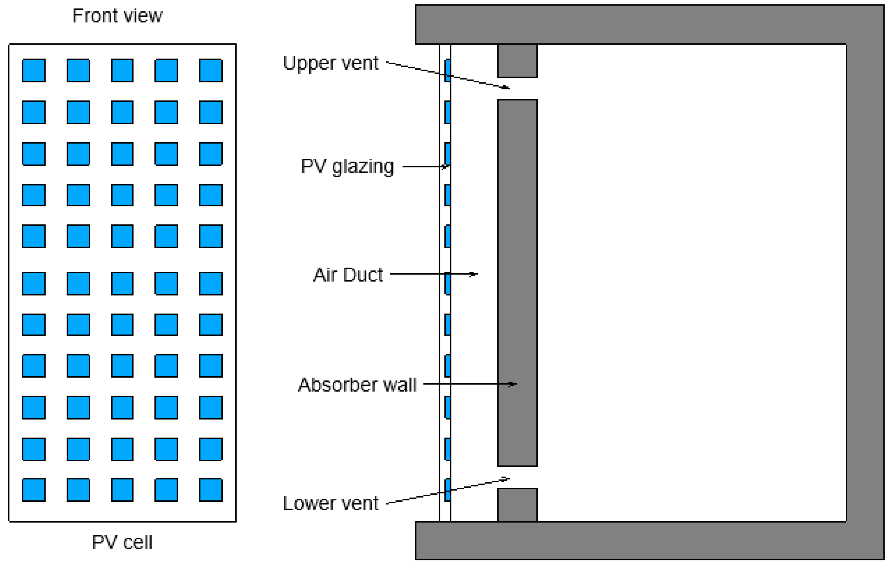
3.1.4. The Trombe Wall with Photovoltaic Cells

The combination of solar panels and the Trombe wall attracts attention as this combination effectively improves thermal comfort and generates electricity.
The use of the Trombe wall may be limited due to the dark surface absorbing light due to high aesthetic requirements for buildings. This problem can be solved using photovoltaic cells with a dark blue tint. A schematic representation of the Trombe wall with photocells is shown in Figure 7 [80,81].
The review article [81] is helpful for engineers and researchers and can provide information for future research work. The review discusses the influence of design and performance parameters on the Trombe wall, including the glass coating, fan use, air gap width, location and width of vents, angle of the solar cell, etc. The main points to note are:
  • With photovoltaic cells, the indoor temperature increases as the width of the Trombe wall increases [82];
  • Research [83] has found the optimum air gap width for buildings in Hong Kong, China (Climate zone according to Köppen is Cfa), and cities with similar climatic conditions. The width of the opening is 0.06 m. The calculation method can be further applied to the Trombe wall studies for the rest of the climate zones;
  • Irshad et al. [80,84,85] presented a room model with a Trombe wall with photovoltaic elements. They evaluated its performance for three different types of glazing: single glazing, double glazing, and double glazing filled with argon. The results showed that double glazing filled with argon showed a significant reduction in cooling load, while the electrical energy production of the panel increased. Studies confirmed that the use of argon-filled double glazing in hot climates would be economically feasible in terms of energy savings and CO2 emissions;
  • Researchers from China [86] conducted a series of experiments to measure and analyze the effect of different solar panel tilt angles on the module’s electricity generation, heat inflow, and changes in air velocity inside the air cavity. The results showed that an inlet air velocity of 0.45 m/s and a PV inclination angle of 50° were considered preferable for such a system;
  • A group of scientists [87] found the optimum ratio of width to height of the air channel to be 0.2. In this case, the ventilation rate through the Trombe wall with photovoltaic elements reaches a maximum.
  • The results [88] showed that during the daytime, the average thermal efficiency of the Trombe wall with the application was 65.2% higher than that of the classical Trombe wall system. The photovoltaic panel was installed in the middle of the channel of the Trombe wall system.
It is important to note that all studies presented above do not involve high-rise construction. A detailed analysis of the Trombe wall design has not been carried out for high-rise buildings. However, they undoubtedly have an excellent potential for solar energy storage due to their substantial glass façades. A comparative analysis of the thermal performance of buildings with different modifications of the Trombe wall, e.g., with a single air gap across the entire façade height and with air gaps for each story, should be carried out.

3.2. Double-Skin Façade (DSF)

Since the early 2000s, the number of buildings with translucent façades has increased significantly. Glass is taking up more and more space in the wall envelope, and in some cases, the entire façade is made of glass. Without any doubt, this gives the building a very particular aesthetic appeal [89,90,91,92]. Glass surfaces accentuate sharp edges and regular curves, making the overall appearance of the building more expressive, tidier, and modern. The growing interest in “glass buildings” would not have been possible if intensive technological advances had not followed. The invention of electrochromic glass with variable transparency, low-emission energy-efficient glass, self-cleaning and water-repellent glass, fire-resistant glass [93], the emergence of aerogel, and innovative glazing systems (structural, semi-structural, modular, and spider glass) have given rise to the most extraordinary architectural ideas.
The article [94] studies how the properties of the window frame affect the change in heat flow and temperature fields. Heat losses are analyzed, depending on some design features of the window frame, such as geometric, thermophysical, and physical properties of walls, windows, lintels, and joints.
The development of science and technology and ongoing engineering research has created a qualitatively new type of glass façade—the double-skin glass façade. The design of a double façade consists of an external glass surface, an air-filled gap, and an internal glazing system (single or double glazing), sometimes combined with opaque walls [95,96,97,98,99]. The gap is ventilated by airflow caused by buoyancy (natural convection) or mechanical devices (forced ventilation). The distance between the glass planes can vary from a few centimeters to 2 m [100]. The heat transmitted to interior spaces is the sum of energies: energy directly transmitted through transparent surfaces from solar heating, secondary radiation from internal glass surfaces, and energy gains from ventilation air.
Nevertheless, glass façades provoke a certain degree of caution and concern among planners and builders. Designers consider the possible overheating in the summer and potential heat loss in the winter period of operation of buildings, which affects the comfort of living indoors and higher energy and utility costs [101,102].
Double façades can be modeled in various software systems, such as EnergyPlus, ESP-r, IES–VE, TRNSYS, IDA–ICE. A comparative analysis of these tools is presented in [103]. It was also found that the number of thermal zones into which the cavity is divided, the coefficient of convective heat transfer, the influence of wind pressure on the airflow in the gap, shading systems, and their position are among the most significant parameters in the modeling process.
There are two ways to create a climate-adaptive double-skin glass façade:
  • The selection of the optimum operation of the air duct. Analysis of the processes taking place in the air gap between the two façade circuits will result in a thoughtful design of the air gap, which will positively affect not only the aesthetic appearance of the building (no condensation on the surfaces) but will also result in savings in energy resources and utility costs.
  • The use of shading devices. Different shading devices can be considered if no rational air channeling solution can be identified after analyzing the various possibilities.
Regarding fire risk assessment, experimental studies have shown that the critical factor is the depth of the gap: wider gaps are safer [100]. It is also better that the façade is divided into compartments. For example, in [104], a school renovation project using a double-skin façade (DSF) system combined with a diffuse ceiling ventilation (DCV) system is presented. A transparent façade is erected in front of the traditional façade. This system is called I-DIFFER. It not only reduces the need for heating in winter but is also an extremely safe fire protection method. Each classroom has its double façade compartment, which prevents the spread of fire, smoke, and sound to neighboring rooms.

3.2.1. Classification of the Double-Skin Façade

The design of a double-skin glazed façade may have different modes of operation in terms of thermal engineering.
  • Globally, double façades can be classified into two large groups: naturally ventilated and pressurized façades.
In work [105], a comparative numerical analysis of the cooling energy performance of a building is presented based on dynamic simulation to calculate the percentage effect of forced ventilation during a period of one year. Four variations of façade designs were considered: a double-skin glazed façade with mechanical ventilation (DL-Case-1), a single-glazed façade with mechanical ventilation (SL-Case-1), a double-skin glazed façade with natural ventilation (DL-Case-2), and a single-glazed façade with natural ventilation (SL-Case-1). The outcomes that were obtained for the environmental conditions of Abu Dhabi (the United Arab Emirates, climate zone according to Köppen is Bwh), Venice (Italy, climate zone according to Köppen is Cfa) and Würzburg (Germany, climate zone according to Köppen is Cfb) are also valid for cities with similar climatic conditions. The energy demand during the cooling period and peak power estimates for these designs are shown in Figure 8.
In Abu Dhabi’s climate, the building’s cooling energy requirement was reduced by 1.5% in Case 1 compared to Case 2 for double interior glazing and 1.9% for single interior glazing. A peak power reduction of 4% was achieved when switching from Option-1 to Option-2 using double glazing, and in the case of single glazing, the reduction was only 2.3%. For Venice, the transition from Option-1 to Option-2 is significant. Cooling energy required is 15% less and peak power is reduced by 11.6% in a double glazing design. For single internal glazing, the savings in cooling energy is 11.5% between the two types of ventilation, and the difference in peak power reaches 8%. Due to the lower ambient temperature in Würzburg compared to Venice, all figures also increased proportionally. The peak power reduction for the double-glazed façade reached 14%. The need for cooling has decreased by 22%. By comparison, single glazing reduces peak power by 9.5% and 17% in cooling [105].
  • There are four types of double-skin façade depending on the airflow path and ventilation system (Figure 9) [34,106,107].
In mode A, room air circulates in the air duct, passing into the HVAC system. The air enters the duct through the lower opening on the inner façade, then it rises and passes into the HVAC. In mode B, fresh air enters the duct through the outdoor duct. In winter, fresh air can be preheated before entering the room. Types A and B are mechanically ventilated. DSF is easily integrated with the building’s HVAC system.
In mode C, the air heats up and rises naturally. Fresh air can be supplied to the room from the street with an open window on the inner façade. If all the windows on the inside of the façade are closed, then the outer wall becomes isolated from the inner space. In this way, the thermal impact on the building during hot periods can be reduced.
In mode D, the double-skin façade behaves like a solar chimney. The room air passes through the bottom vent into the duct. After passing the duct, the air goes directly to the environment. When installing an air intake, it is possible to realize natural ventilation of the room without air conditioning.
  • The double-skin façade is also classified according to internal geometry. The classification is presented in works [107,108,109,110,111,112], visually represented in Figure 10.

3.2.2. Shading Devices for Double-Skin Façades

Scientists pay particular attention to shading systems. Various shading solutions from blinds to “natural” blinds, where the double façade opening is planted [113,114,115,116,117], were proposed worldwide. Using computer modeling, Stec et al. [113] showed that placing vegetation inside the cavity of the double façade can provide a comfortable indoor microclimate. The researchers compared the thermal performance of two shading devices inside the double-skin glass façade: bio-shading and using louvers. The result showed that the green layer had a lower surface temperature (35 °C) than the louvers (55 °C). It is estimated that this leads to a reduction in the energy consumption of air conditioning systems by up to 20%.
G. Baldinelli [96] presented an analysis of a double-skin façade with integrated movable shading devices. Such a design was developed to overcome possible summer overheating. The model was created for a south-facing façade, taking into account the climatic data of central Italy (Cfa). The trajectory of the sun was taken into account using the ray-tracing method. The modeling was compared with data from a similar experimental installation (Figure 11).
The winter configuration of the proposed façade allows for a doubling of solar heat despite the shading systems. In summer, the solar heat is mainly absorbed by the outer glass layer. There is no significant impact on the inner glass surface and the interior environment, which reduces the cooling requirements of the building and saves on air conditioning. The performance of this type of façade was compared with traditional building envelopes, with single pane glass and opaque walls in an office building in central Italy. A year-long study showed that the proposed façade significantly improves the energy performance of the building.
In work [118], an example of optimizing a double façade system for innovative façade systems is presented. The optimization occurs through the lamellas rotation in the cavity and the ventilation flaps at the top and bottom of the outer and inner glazing layer. One of the characteristic features of the system is its ability to react dynamically to environmental inputs. User interaction with the system is enabled via the internet. The user can select a preferred mode of operation or block devices (blinds, inlet/outlet vents).
A study [119] numerically investigated the thermal performance of a double façade using the hot climate conditions of Saudi Arabia (climate zone according to Köppen is Bwh). This study considered the effect of the cavity geometry, the size of the openings between the shading device lamellae on the airflow pattern, and air temperature distribution. To assess the influence of the studied variables on the double façade’s design, 13 calculation models, 12 of which had a shading device and one without a shading device, were built using computational fluid dynamics (Figure 12).
The following conclusions can be drawn from the simulation:
  • By increasing the size of the openings for the channel width of 0.3 m and 0.6 m, the airflow speed increases. With a cavity width of 1.2 m, the air velocity does not change when the size of the holes changes (about 0.14 m/s);
  • As the size of the holes decreased, the temperature inside also decreased. On the contrary, the expansion of the cavity led to an increase in temperature. With the same hole sizes, the temperature inside the cavity increased as the width of the cavity increased. In addition, increasing the opening can lower the air temperature inside. An average temperature of 26 °C to 50 °C was observed in both cases;
  • As the size of the holes increase, the heat transfer in the cavity decreases. The device of shading equipment contributes to the dissipation of heat in the cavity;
  • The temperature inside the cavity is more critically affected by changing the size of the holes than changing the width of the cavity;
  • Further research will examine the shading device’s position in the cavity and consider different shading devices’ respective energy performances using Computational fluid dynamics (CFD) and building energy simulations in hot climates.
The results of works [120,121] show that Venetian blinds can reduce the influx of solar heat. The thermal collector DSF-VB can reduce the solar heat gain by up to 19% (for the east/west façade) or up to 22% (for the south façade) of the total incident radiation during a year’s operation.
Ling Zhang et al. [122] proposed using blinds with photocells as a shading device in a double façade. Such a design could fulfill several functions at once: power generation, flexible control of daylighting in the room, and reduction of solar radiation penetration. The experiment was conducted in the Hunan province, China, in a region with hot summers and cold winters under field conditions. The angle and spacing of the photo blades were varied. A comparative study showed that a double-skin façade with photovoltaic modules could save around 12.16% energy in summer compared to a conventional DSF with louvers and 25.57% with a DSF without louvers. The results assumed operation in natural ventilation mode and indicated a noticeable effect of the distance between the solar panels on system performance. The movable façade configuration involves detailed design on a case-by-case basis and higher investment costs, making it challenging to distribute this system widely and quickly.
An important issue regarding the application of sun shading devices is the question of their positioning. Inside the gap, they are protected from the weather. Still, they alter the airflow in the duct and, if installed incorrectly or miscalculated, can negatively influence the entire system. On the other hand, external Venetian blinds are in direct contact with the outside air, wind, and rain, but they offer better protection from the incident solar heat. Researchers from Belgium [123] have considered this question in a multi-faceted way. They took into account factors such as the color of the shading devices; the position within the cavity—closer to the outer plane, closer to the inner plane, or in the middle; the presence or absence of ventilation openings. Placing light shading devices in the middle of the air cavity with ventilation openings can save up to 23.3% on space cooling during hot periods.
As a sun protection measure and to prevent the building from overheating, sun screening tinting films can also be used, as suggested in [124,125] to do for windows.

3.2.3. Photovoltaic Cells in Double-Skin Façades

The use of photovoltaic cells as movable lamellas for shading and the outer surface of a double-skin glass façade is considered by many researchers. An example of this use is the study carried out by the public library building in Mataro, Spain [126]. The outer surface of the façade contains 20 kWh multi-crystalline photovoltaic cells inside the transparent glass, giving a translucent appearance to the façade. The ventilated space is 140 mm thick, and the inner surface is made of glass.
An example of a ventilated window with photovoltaic cells is described in [127]. Based on the energy model of the building, as well as the Hong Kong weather data (climate zone according to Köppen is Cfa), a general performance analysis was carried out for different window orientations. It was found that a solar cell transmittance of 0.45–0.55 could provide the best energy savings. The conclusions drawn in the study can be extended to the double ventilated façade due to the similar operating principle.
The previously mentioned work [105] compared the effect of photovoltaic panels in a double-skin façade with forced ventilation (Case-1) and natural ventilation (Case-2), using cities in different climatic regions (Abu Dhabi, Venice, and Würzburg). A summary of the annual results of the integrated PV system in the three cities is shown in Figure 13a,b.
Forced ventilation and photovoltaic cells increase annual energy production by 2.5% in Abu Dhabi for double-glazing and 6% for single-glazing. In Venice, annual photovoltaic electricity production reached 53% with double glazing and 34% with single glazing. A similar pattern of performance occurred in the city of Würzburg. The improvement was 57% with double glazing and 50% with single glazing.
The results [128] showed that the use of building-integrated photovoltaic cells as exterior solar shading devices produces on-site electricity and reduces cooling loads by 10% and 9.2%
Integrating photovoltaic cells with the building façade is considered energy-efficient if the photovoltaic cell does not overheat. High summer temperatures can increase the air temperature in the cavity of the double façade and reduce the overall energy efficiency of the photovoltaic cells. This process can result in a 0.4–0.5% loss of solar-to-electric conversion efficiency [112]. Work [127] is a numerical study of the thermal behavior of a mechanically ventilated double-skin façade integrated with a photovoltaic cell by cooling the air cavity with supplied cold fresh air. The DSF scheme used is shown in Figure 14. The type of air inlet, its location, and the deflection angles of the airflow are investigated.

3.2.4. Low-Emission Glass in Double-Skin Façades

Researchers suggest that the inner glass surface should be made of low-emissivity glass to prevent heat loss from the building [129]. The principle of low-emissivity glass is described in [130]. Any opaque object absorbs some solar energy and heats up when exposed to sunlight. At the same time, it emits energy in the form of infrared wavelengths. In summer, low-emissivity glass can let insufficient sunlight for illumination. Still, at the same time, it blocks infrared radiation produced by exterior roads and buildings due to the absorption of the sun. It significantly reduces the need for air conditioning in rooms. In winter, low-emission glass can also let in some visible solar energy. Still, at the same time, it reflects long-wave radiation from indoor heating equipment, human heat, and lighting fixtures. Such heat loss does not occur in winter. Consequently, low-emissivity glass can effectively maintain the temperature in a room.
According to [129], low-emissivity glass offers better natural ventilation at all angles of incidence of sunlight (10–80°) and solar radiation intensity (50–1000 W/m2) (by approximately 13%). The airflow rate is reduced at higher incidence angles. Incidence angles of less than 40° result in insignificant reductions in air velocity (<4% per 10°), whereas tips > 40° development in more drastic decreases (8% per 10°). Thus, a double-skin façade with low-emissivity glazing of the inner plane provides more natural ventilation at lower angles of incidence of sunlight. An optimum airflow rate can be obtained with a cavity gap of 0.15–0.3 m.

3.2.5. Double-Skin Façade with Innovative Materials

Phase-change materials (PCM) are promising materials. In the building industry, integrating PCM materials into various structural elements or heating, ventilation, and air conditioning (HVAC) components can increase the thermal capacity. In turn, it helps reduce indoor temperature fluctuations, thereby decreasing the heating and cooling loads [131].
Goia et al. [132,133,134] compared a conventional glazing unit (DGU_CG-double-skin glass Unit Clear Glass) with a glazing unit with PCM (DGU_PCM). The width of the cavity between the transparent panels is 15 mm. In the first case, it is filled with air. In the second, the cavity is filled with RT35 technical paraffin. Goia’s development was, in turn, based on [132]. Measurements were made using the TWINS-Testing Window Innovative System (Figure 15) [132,135].
The measuring system consisted of 40 sensors. The sensor system measures the physical parameters of the double-glazed windows. Climatic conditions inside and weather conditions outside the chamber are also recorded by sensors. The tests were carried out for six months.
The change in the appearance of paraffin glazing during the day can be observed in Figure 16, which shows changes in the aggregate state, as well as changes in the transparency of paraffin in the façade during measurements from 10:00 to 19:00 [136]. Measurements were taken every hour. The results were obtained in summer during sunny weather. During this period, the layer of phase-change material completely melts and solidifies again. The dynamics of melting and solidification of the PCM layer are monitored by researchers by changing the transparency of the glazing. Until 13:00, PCM is in the solid phase. At this time, the PCM has a translucent appearance. At 14:00, it becomes clear from observations that most of the solid PCM floats in the volume of liquid PCM. At 16:00, the entire mass of PCM is in a liquid state. The studied PCM layer is completely transparent. Solidification of liquid PCM begins after 18:00. At 19:00, most of the PCM becomes solid and also translucent.
It was found that the thermal conditions of the indoor environment façade achieved using the DGU_PCM façade were significantly better than the DGU_CG façade for most of the time during the different seasons. In general, it was observed that the higher the level of solar radiation outside, the more benefits DGU_PCM offers. However, the careful optimization of the wax’s forward and reverse change temperature from the solid to the liquid state in glazing is still subject to study. When the wax is completely melted, the temperature of the glass panels and the incoming heat fluxes increase significantly, reducing the performance of the window system and affecting its integrity. PCM reduces the specific daily entering energy by about 20–55% compared to a conventional double-glazing system. The result obtained by the authors suggests the use of phase-change material specifically in glazing, which is a reduced variation of a double-skin glass façade with a closed cavity. The scientific literature also referred to closed cavity façades [38,39,137].
The authors further investigated a glass façade with three transparent panels and two air cavities [138], filling each with a phase-change material in turn. Two configurations were tested, and although both can significantly increase the solar gains compared to conventional triple glazing (up to 68%), the configuration with the PCM placed in the innermost cavity of the glazing unit shows even better performance.
The article [139] discusses the use of different façades (traditional, double-skin façade and façade with PCM) in a high-rise office building using Energy Plus for the cities of Jeddah, Abha, and Tabuk in Saudi Arabia. The climate zone, according to Köppen, is Bwh (Hot desert climate), Cwa (Monsoon-influenced humid subtropical climate), and Bwh (Hot desert climate). The analysis results show that the use of DSF in the city of Tabuk leads to savings in thermal energy in winter and an increase in cooling demand in summer compared to a traditional façade. The use of PCM reduces the need for heating energy in winter and cooling in summer. A similar trend can be seen in the city of Jeddah. Using a DSF with PCM reduces energy consumption in cold and hot months compared to a simple dual-shell façade. In general, it increases the energy consumption in Abha city.
In combination with other solar energy conversion technologies, PCM is also efficient and feasible, e.g., in photovoltaic modules, they are used for temperature maintenance. Commercial PV cells can only convert solar radiation of around 14–20% into electrical energy [111]. The remaining solar radiation is converted into apparent heat, which causes the PV cell to heat up. Phase-change materials help to prevent the module from overheating. The numerical model results were confirmed by experimental data obtained from a test bench in Palermo, Italy [140].
In the article [136], a double-skin glass façade is investigated, with the joint application of a photovoltaic (PV) layer and a phase-change material (PCM) layer. A physical and mathematical model is developed to simulate the dynamic heat fluxes in the system. Numerical simulations are carried out for different climatic conditions (Venice, Helsinki, and Abu Dhabi) and are based on previous studies by the authors [105,141].
The cavities were assumed to be ventilated with forced ventilation using the outside air exhaust method (Figure 17) [136].
According to the calculations made, the following conclusions can be drawn. Firstly, there is no need to integrate a phase-change material layer for photovoltaic panels during the heating season. From the moment cooling is required in the building, the demand for the innovative material increases. The cooling load is reduced by an average of 22%, irrespective of the climate. Secondly, with PCM, the average surface temperature of the photovoltaic module is reduced. Simulations using a simplified method of ventilation control show that it is possible to reduce the temperature of the PV module by up to 20 °C. It has a positive impact both on the thermal load of the building and on the efficiency of the conversion of electrical energy from photon energy.
To improve the energy performance of a building, scientists are developing new ideas and investigating the effect of using various innovative materials. Researchers [142] used polyvinyl chloride (PVC) coated polyester fabric as the second layer in a double façade. This type of fabric is characterized by excellent tensile strength. For the experiment, two outdoor test facilities were built. They evaluated design performance and provided calibration and numerical model validation data to TRNSYS. Modeling of the reconstruction of a typical three-story office building was carried out using this type of double façade with an innovative material. The study found that PVC-coated polyester fabric as the material for the second layer of a double façade can improve PES (Primary Energy Saving) by up to 6.1% and reduce cooling energy demand by up to 29.3%.
The article [143] studied extruded Acrylonitrile–Butadiene–Styrene (ABS) panels as the second layer of a double façade. Numerical modeling was carried out, where the type of polymer, manufacturing technology, and extrusion are varied. Panels made using 3D printing were also considered. Modeling was carried out to assess the potential savings of non-renewable primary energy and the possible reduction in heating and cooling power demand. All investigated options showed positive results in terms of Primary Energy Saving (PES).

3.2.6. Double-Skin Façade with an Inclined Plane

The article [144] considers the case when a double-skin façade has an inclined outer plane. If for aesthetic reasons, the architect decides to slope one of the walls, then this leads to significant changes in the design from the point of view of thermal engineering. As the wall slopes, the Nusselt number and the flow velocity decrease. The study was aimed at quantifying the wear and tear of the system using the French climate as an example. Changing the angle of inclination has a great influence on the heat transfer processes. At the angle of inclination α = 0°, the most intense heat transfer rate is observed. This is a classic case with an ordinary wall. Additionally, in the case of a non-inclined channel, the maximum mass flow occurs. This is also possible when the channel inclination angle is α = −2°. The researchers say the −10° angle is the optimal compromise between architectural considerations and heat and mass transfer. The inclined glass façade plane case can be observed at the Lakhta Centre building in St. Petersburg, Figure 18 [145].
Another option of an inclined external glass surface in a double-skin façade implementation is to create a productive architectural surface system (PASS). A productive double-skin façade (PDSF) is its integral part (Figure 19) [146].
The design of the PDSF is an energy-saving indoor area, and it can co-generate solar electricity and heat and transmit daylight to the interior space.
PDSF is a space for comfortable growing plants, where light and shade meet plant growth’s functional requirements and habits. In such a tightly controlled environment, vegetable yields will be higher, and the most appropriate technology will shorten the growth cycle. Such systems can take advantage of aeroponics or aquaponics. All these benefits serve to create sustainable urban development [146].

3.3. Comparative Analysis of the Trombe Wall and the Double-Skin Façade

A comparison of the two designs is clearly shown in Table 2.

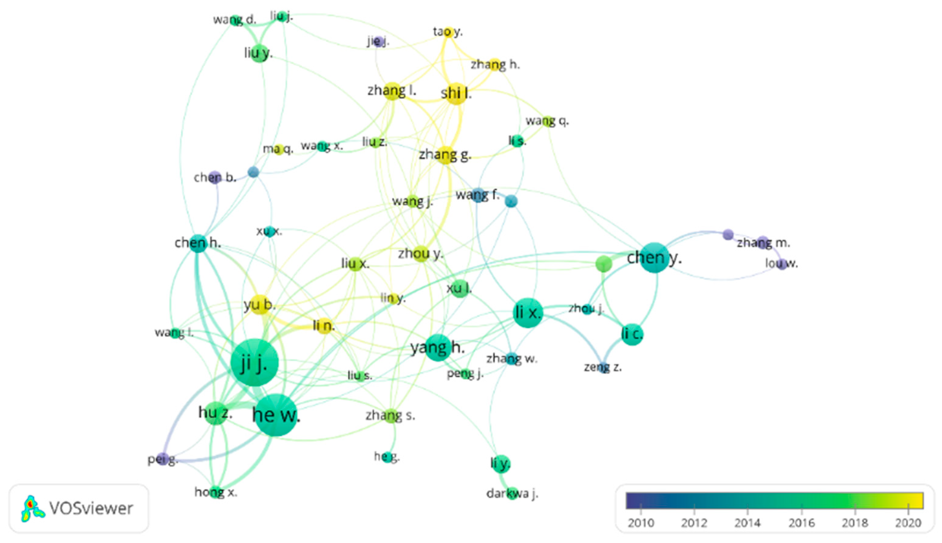
4. The Scientometric Analysis of Articles in the Direction “Climate-Adaptive Façades”

Bibliometric analysis is a statistical method used to evaluate the published literature [147,148]. The names of the SciVal topics were given, according to which the review was carried out. The topic “Climate-adaptive façades” does not yet exist (accessed on 21 January 2022). Therefore, for scientometric analysis, the Publication Set was formed, including papers with the keywords “Climate-adaptive façades”, “Double-skin façade”, “Trombe wall and “DSF”. The selected publications are analyzed below using the SciVal tools and the VosViewer software.
First of all, keyword match analysis in a field of study can be a tool for identifying popular destinations [149,150]. An example of the distribution of keywords and clusters in the VosViewer software is shown in Figure 20.
According to this distribution, the most popular keyphrases are:
  • Trombe wall;
  • Double-skin façade;
  • Natural ventilation;
  • CFD (Computational Fluid Dynamics);
  • Solar energy.
Figure 20 shows a clustering of the most frequently used keywords in climate-adaptive façade publications over the past five years. A cluster is a group of closely related elements. The yellow circles and yellow lines represent the most up-to-date clusters. Among them are such areas as renewable energy (Figure 21a), heat flux (Figure 21b), phase-change material (Figure 21c), Mediterranean climate (Figure 21d).
Figure 22 reflects a network of authors working in the field of climate-adaptive façades. The larger the circle of the author’s name, the more times his work was cited by the scientific community. The lines connecting the researchers represent the joint work of the authors. The distance between the circles and the length of the connection is determined on the basis of the strength of their professional interaction [149].
Countries in which researchers are actively developing the topic of climate-adaptive façades can be seen in Figure 23. China, the United States of America, the United Kingdom, Italy, and Australia are leaders among others in this topic.
The main indicators characterizing the relevance of the topic in the scientific community are presented in Table 3.
The rating of organizations by the number of publications is presented in Table 4.
Russia is ranked 224 out of 324. According to the analysis, the organization actively developing climate-adaptive façades is Peter the Great St. Petersburg Polytechnic University (Saint-Petersburg, Russia) [36].
The topic of climate-adaptive façades is about energy and construction and covers various industries. According to Figure 24, such façades are of interest to ecologists, mathematicians, chemists, and other specialists.
The publication set “Climate-adaptive façades” is one of the directions of a broader topic “Façades; Blinds; Natural Ventilation”. Further graphs characterize the contribution of the subject under study to a broader area (Figure 25, Figure 26, Figure 27 and Figure 28).

5. Discussion

Analysis of the previous studies on climate-adaptive façade structures using the Trombe wall and the double-skin façade since 2005 was carried out. A brief systematization of the previously conducted studies and obtained results is given in Table 5.
The analysis has shown that the previously conducted studies in various climatic zones are insufficient. In order to design climate-adaptive façade structures and benefit from energy savings, it is necessary to collect data on the behavior of the double-skin façade in climate zones other than Bwh, Cfa, Cfb, Csa, Csb, Cwa, Dfb, and the behavior of the Trombe wall in climate zones other than Af, Bwh, Cfa, Cfb, Csb, Csa, Cwb, Dsb, Dsc. Thus, a database will be collected to design façade structures in any conditions. Consequently, the presence of such studies leads to both architecturally improved and more energy-efficient buildings.
The study’s outcome has shown that the Trombe wall has not been studied for high-rise buildings, in contrast to the double-skin façade ([107,123] and others).
Moreover, PV modules with PCM are considered the most energy-saving solution since PCM protects the module’s overheating.
Additionally, this article presents for the first time a scientometric analysis on the topic “Climate-adaptive structure”. It is important to note that scientometric analysis through the static processing of scientific information characterizes the productivity and development vectors of the topic under study. According to the VosViewer analysis, the most popular studies on this topic are related to the work of the following authors: Ji J. [31,51,82,86], He W. [51,86,127], Hu Z. [51,86], Shi L. [129] and Yang H. [34,151]. The first three authors investigated the Trombe wall, while the last two studied the double-skin façades.
Although some studies were conducted on the Trombe wall façade system, further studies in this direction are still required due to its advantages. In these areas, the authors see the main tasks for further development.
According to SciVal analysis, the most advanced center on this topic belongs to the University of Science and Technology in China.

6. Recommendations

The outcome of this article has shown that the following trends are recommended for future studies:
  • A more comprehensive study on the influence of PV modules with PCM combination on the Trombe wall and double-skin façade systems for different climatic zones.
  • An economic study of the above-addressed systems for various residential, industrial, and public buildings.

7. Conclusions

The growing demand for energy and the environmental problems associated with energy production increase the necessity to advance energy conservation systems. One of the sustainable development trends is the development and application of energy-efficient climate-adaptive designs. In the present study, a detailed literature review was carried out on the critical contribution of the Trombe wall and double-skin façade as an adaptive climate system.
The outcome of the results has shown the following:
  • The Trombe wall does not require significant initial or operational costs. The south wall of almost any low-rise house can easily be reconstructed into a Trombe wall. Subject to the individual properties, this can save between 20% and 25% in energy costs for heating.
  • The research presented in this review examines the Trombe wall concerning low-rise construction. Further research should be devoted to studying this system for multi-story buildings, as multi-story buildings are active energy consumers.
  • An analysis of research work on double-skin façades shows that they are more energy-efficient than other traditional systems. The amount of energy resources required for air-conditioning of a building is reduced by 20–30%.
  • Double façade photovoltaic cells increase annual energy production by 57% in the Cfb climate. The Trombe wall combined with photocells becomes 65.2% more productive in the Cfa climate.
  • The performance of photovoltaic cells can be reduced by 0.4–0.5% in case of overheating. Studies show that integrating PCM layers in double-skin façades and Trombe systems with photovoltaic modules can effectively reduce the cooling load and increase the conversion efficiency of solar energy into electrical energy.
  • The Trombe system and double-skin façade design were studied in the following climatic zones (Af, Bwh, Cfa, Cfb, Csa, Csb, Cwa, Cwb, Dfb, Dsb, Dsc). For the structure to be as climate-adaptive and climate-responsive as possible, it is necessary to collect data on its behavior in other climatic regions according to the Köppen classification.
  • The analytical outcome of the studied data was mainly devoted to translucent double-skin façades, where both shells are glass. However, it is significant to note that other materials are also improving and can compete with glass, forming an energy-efficient system. PCM, polyester fabric, and extruded acrylonitrile butadiene styrene (ABS) panels offer innovative solutions in this area.
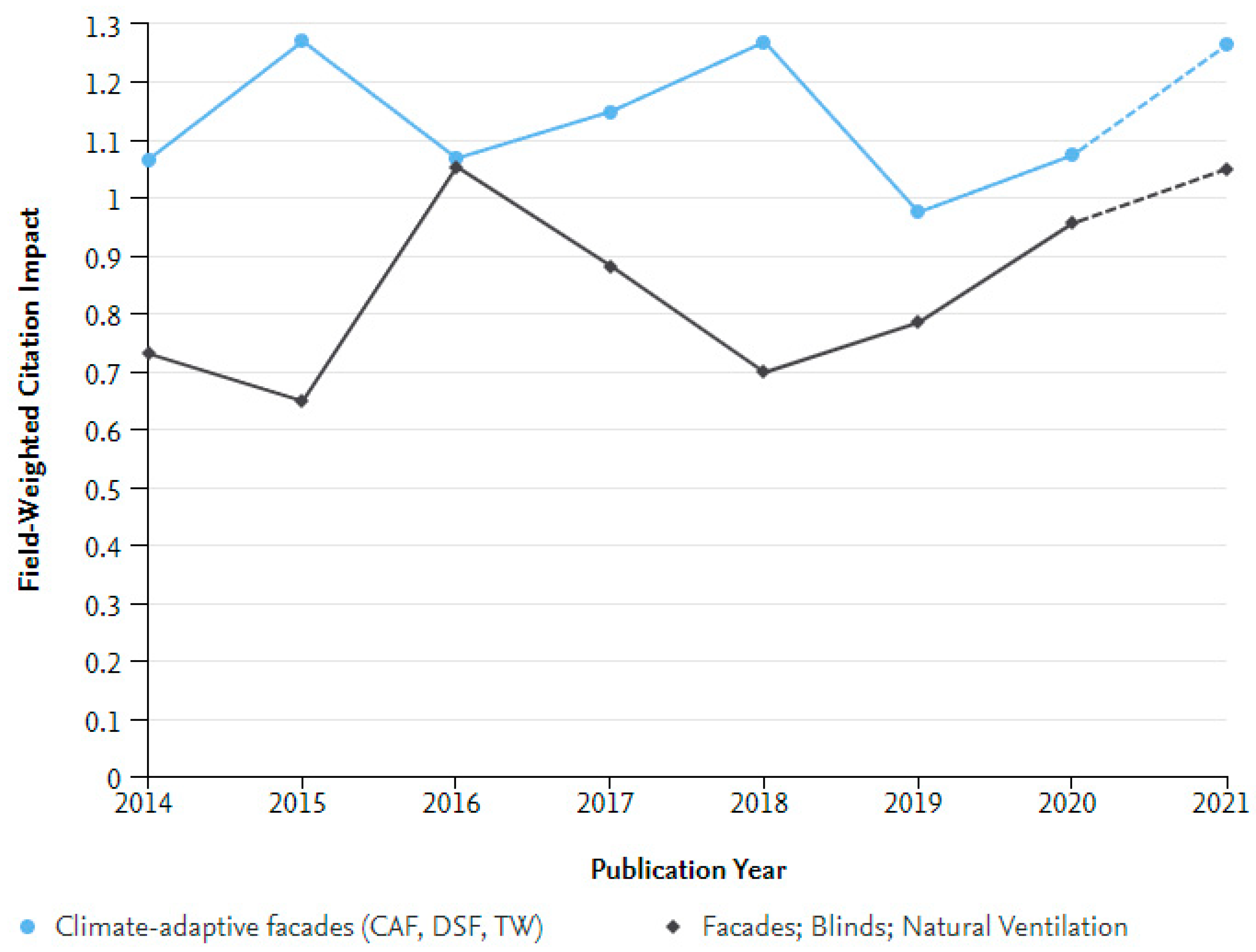
  • According to the scientometric analysis performed using the SciVal and VosViewer tools, some trends can be seen. The topic “Climate-adaptive façades” is prevalent in China according to the level and the number of publications in this area made by Chinese organizations and institutions. Moreover, Peter the Great St. Petersburg Polytechnic University can be considered pioneers in this field in the territory of the Russian Federation. Comparison of the publication set “Climate-adaptive façades” and the broader topic “Façades; Blinds; Natural Ventilation” shows that in the last five years, the first topic has received more attention from the scientific community (more publications in top magazines).

Author Contributions

This research paper results from a joint collaboration of all the involved authors. Conceptualization: I.L.V., D.V.N., N.I.V., R.S F. and M.I.K.; software: D.V.N. and I.L.V.; writing—original draft preparation: I.L.V.; editing: N.I.V.; supervision: N.I.V. and R.S.F.; All authors have read and agreed to the published version of the manuscript.

Funding

This work is supported by the Russian Science Foundation under grant 21-79-10283, date 29 July 2021, https://rscf.ru/project/21-79-10283/ (accessed on 29 July 2021).

Institutional Review Board Statement

Not applicable.

Informed Consent Statement

Not applicable.

Data Availability Statement

The data presented in this study are available on request from the corresponding author.

Acknowledgments

The authors are grateful to the Laboratory of Self-Healing Structural Materials of the Center for the National Technological Initiative “New Manufacturing Technologies” (Peter the Great St. Petersburg Polytechnic University, St. Petersburg 195251, Russia) for recommendations and advice.

Conflicts of Interest

The authors declare no conflict of interest. The funders had no role in the design of the study; the collection, analyses, or interpretation of data; the writing of the manuscript; or in the decision to publish the results.

Abbreviations

ABSAcrylonitrile–Butadiene–Styrene
AfTropical rainforest climate
BwhHot desert climate
CAFClimate-adaptive façade
CfaHumid subtropical climate
CfbTemperate oceanic climate
CFDComputational fluid dynamics
CNTCarbon nanotubes
CsaMediterranean hot summer climates
CsbWarm-summer Mediterranean climate
CwaMonsoon-influenced humid subtropical climate
CwbOceanic Subtropical Highland Climate
DfbWarm-summer humid continental climate
DsbMediterranean-influenced warm-summer humid continental climate
DscMediterranean-influenced subarctic climate
DSFDouble-skin façade
FWCIField-Weighted Citation Impact
HVACHeating, ventilation, and air conditioning
PASSProductive architectural surface system
PCMPhase-change material
PDSFProductive double-skin façade
PESPrimary energy saving
PVPhotovoltaic
PVCPolyvinyl chloride
TWTrombe wall
VBVenetian blinds

References

  1. Hannan, M.A.; Al-Shetwi, A.Q.; Ker, P.J.; Begum, R.A.; Mansor, M.; Rahman, S.A.; Dong, Z.Y.; Tiong, S.K.; Mahlia, T.M.I.; Muttaqi, K.M. Impact of renewable energy utilization and artificial intelligence in achieving sustainable development goals. Energy Rep. 2021, 7, 5359–5373. [Google Scholar] [CrossRef]
  2. Cellura, M.; Fichera, A.; Guarino, F.; Volpe, R. Sustainable Development Goals and Performance Measurement of Positive Energy District: A Methodological Approach. Smart Innov. Syst. Technol. 2022, 263, 519–527. [Google Scholar] [CrossRef]
  3. Vasileva, I.; Nemova, D.; Kotov, E.; Andreeva, D.; Ali, M. Al The Use of Aerogel in Building Envelopes. Lect. Notes Civ. Eng. 2020, 70, 793–802. [Google Scholar] [CrossRef]
  4. Liu, C.; Zhou, Y.; Li, D.; Meng, F.; Zheng, Y.; Liu, X. Numerical analysis on thermal performance of a PCM-filled double glazing roof. Energy Build. 2016, 125, 267–275. [Google Scholar] [CrossRef] [Green Version]
  5. Kong, X.; Lu, S.; Li, Y.; Huang, J.; Liu, S. Numerical study on the thermal performance of building wall and roof incorporating phase change material panel for passive cooling application. Energy Build. 2014, 81, 404–415. [Google Scholar] [CrossRef]
  6. Gorshkov, A.S.; Vatin, N.I.; Rymkevich, P.P.; Kydrevich, O.O. Payback period of investments in energy saving. Mag. Civ. Eng. 2018, 78, 65–75. [Google Scholar] [CrossRef]
  7. Brito-Coimbra, S.; Aelenei, D.; Gomes, M.G.; Rodrigues, A.M.; Gomes, G.; Rodrigues, M.; Façade, A.B. Building Façade Retrofit with Solar Passive Technologies: A Literature Review. Energies 2021, 14, 1774. [Google Scholar] [CrossRef]
  8. Al-Yasiri, Q.; Szabó, M. Incorporation of phase change materials into building envelope for thermal comfort and energy saving: A comprehensive analysis. J. Build. Eng. 2021, 36, 102122. [Google Scholar] [CrossRef]
  9. Milajić, A.; Beljaković, D.; Davidović, N.; Vatin, N.; Murgul, V. Using the Big Bang—Big Crunch Algorithm for Rational Design of an Energy-Plus Building. Procedia Eng. 2015, 117, 911–918. [Google Scholar] [CrossRef] [Green Version]
  10. Zhang, H.; Shang, C.; Tang, G. Measurement and identification of temperature-dependent thermal conductivity for thermal insulation materials under large temperature difference. Int. J. Therm. Sci. 2022, 171, 107261. [Google Scholar] [CrossRef]
  11. Tychanicz-Kwiecień, M.; Wilk, J.; Gil, P. Review of high-temperature thermal insulation materials. J. Thermophys. Heat Transf. 2019, 33, 271–284. [Google Scholar] [CrossRef]
  12. Hung Anh, L.D.; Pásztory, Z. An overview of factors influencing thermal conductivity of building insulation materials. J. Build. Eng. 2021, 44, 102604. [Google Scholar] [CrossRef]
  13. Lakatos, Á.; Kalmár, F. Investigation of thickness and density dependence of thermal conductivity of expanded polystyrene insulation materials. Mater. Struct. Constr. 2013, 46, 1101–1105. [Google Scholar] [CrossRef] [Green Version]
  14. Vatin, N.I.; Gorshkov, A.S.; Nemova, D.V.; Staritcyna, A.A.; Tarasova, D.S. The energy-efficient heat insulation thickness for systems of hinged ventilated façades. Adv. Mater. Res. 2014, 941–944, 905–920. [Google Scholar] [CrossRef]
  15. Capeluto, G. Adaptability in envelope energy retrofits through addition of intelligence features. Archit. Sci. Rev. 2019, 62, 216–229. [Google Scholar] [CrossRef] [Green Version]
  16. Abdullah, Y.S.; Al-Alwan, H.A.S. Smart material systems and adaptiveness in architecture. Ain Shams Eng. J. 2019, 10, 623–638. [Google Scholar] [CrossRef]
  17. Barozzi, M.; Lienhard, J.; Zanelli, A.; Monticelli, C. The Sustainability of Adaptive Envelopes: Developments of Kinetic Architecture. Procedia Eng. 2016, 155, 275–284. [Google Scholar] [CrossRef] [Green Version]
  18. Elzeyadi, I. The impacts of dynamic façade shading typologies on building energy performance and occupant’s multi-comfort. Archit. Sci. Rev. 2017, 60, 316–324. [Google Scholar] [CrossRef]
  19. Chen, H.; Wang, E.; Li, Q. Towards the Climate Adaptive Residential Buildings Design. Appl. Mech. Mater. 2012, 193–194, 40–44. [Google Scholar] [CrossRef]
  20. Shan, R.; Junghans, L. “Adaptive radiation” optimization for climate adaptive building façade design strategy. Build. Simul. 2017, 11, 269–279. [Google Scholar] [CrossRef]
  21. Xu, W. Environmental Performance Optimization Design of Marine Climate Adaptive Green Public Buildings. J. Coast. Res. 2020, 106, 342–346. [Google Scholar] [CrossRef]
  22. Qi, J.; Wei, C. Performance evaluation of climate-adaptive natural ventilation design: A case study of semi-open public cultural building. Indoor Built Environ. 2021, 30, 1714–1724. [Google Scholar] [CrossRef]
  23. Shen, J.; Copertaro, B.; Zhang, X.; Koke, J.; Kaufmann, P.; Krause, S. Exploring the Potential of Climate-Adaptive Container Building Design under Future Climates Scenarios in Three Different Climate Zones. Sustainability 2020, 12, 108. [Google Scholar] [CrossRef] [Green Version]
  24. Shen, J.; Copertaro, B.; Sangelantoni, L.; Zhang, X.; Suo, H.; Guan, X. An early-stage analysis of climate-adaptive designs for multi-family buildings under future climate scenario: Case studies in Rome, Italy and Stockholm, Sweden. J. Build. Eng. 2020, 27, 100972. [Google Scholar] [CrossRef]
  25. Golzan, S.S.; Pouyanmehr, M.; Naeini, H.S. Recommended Angle of a Modular Dynamic Façade in Hot-Arid Climate: Daylighting and Energy Simulation; Emerald Publishing Limited: Bingley, UK, 2021. [Google Scholar] [CrossRef]
  26. Kumar, V.V.; Raut, N.; Akeel, N.A.; Zaroog, O.S. Experimental investigation of cooling potential of a ventilated cool roof with air gap as a thermal barrier. Environ. Dev. Sustain. 2022, 1–14. [Google Scholar] [CrossRef]
  27. Lima-Téllez, T.; Chávez, Y.; Hernández-López, I.; Xamán, J.; Hernández-Pérez, I. Annual thermal evaluation of a ventilated roof under warm weather conditions of Mexico. Energy 2022, 246, 123412. [Google Scholar] [CrossRef]
  28. Shao, N.; Ma, L.; Zhou, C.; Zhang, D. Experimental study on the heat transfer performance of the PVT ventilated roof as heat exchanger for heat pump system. Renew. Energy 2022, 187, 995–1008. [Google Scholar] [CrossRef]
  29. Domínguez-Torres, C.A.; León-Rodríguez, Á.L.; Suárez, R.; Domínguez-Delgado, A. Empirical and Numerical Analysis of an Opaque Ventilated Façade with Windows Openings under Mediterranean Climate Conditions. Mathematics 2022, 10, 163. [Google Scholar] [CrossRef]
  30. Khalvati, F.; Omidvar, A.; Hadianfard, F. Study on summer thermal performance of a solar ventilated window integrated with thermoelectric air-cooling system. Int. J. Energy Environ. Eng. 2021, 12, 419–432. [Google Scholar] [CrossRef]
  31. Wang, C.; Uddin, M.M.; Ji, J.; Yu, B.; Wang, J. The performance analysis of a double-skin ventilated window integrated with CdTe cells in typical climate regions. Energy Build. 2021, 241, 110922. [Google Scholar] [CrossRef]
  32. Khosravi, S.N.; Mahdavi, A. A CFD-Based Parametric Thermal Performance Analysis of Supply Air Ventilated Windows. Energies 2021, 14, 2420. [Google Scholar] [CrossRef]
  33. Conceição, E.; Gomes, J.; Lúcio, M.M.; Conceição, M.I.; Awbi, H. Construction of an Experimental Chamber Equipped with Ventilated Windows. Adv. Sci. Technol. Innov. 2021, 405–410. [Google Scholar] [CrossRef]
  34. Zhang, T.; Tan, Y.; Yang, H.; Zhang, X. The application of air layers in building envelopes: A review. Appl. Energy 2016, 165, 707–734. [Google Scholar] [CrossRef]
  35. Poerschke, U.; Rim, D.; Pei, G.; Mirhosseini, H. The ‘Air-Wall’: Re-Evaluating a Mid-Twentieth Century Four-Sided Double-Skin Façade. Technol. Archit. Des. 2019, 3, 200–210. [Google Scholar] [CrossRef]
  36. Barabash, A.; Naumova, E.; Zhuvak, O.; Nemova, D.; Olshevskiy, V. The Efficiency of the Ventilated Gap of the Double-Skin Façade Systems Using Fire Crosscuts. In Proceedings of the XV International Conference Topical Problems of Architecture, Civil Engineering, Energy Efficiency and Ecology—2016, Tyumen, Russia, 27–29 April 2016. [Google Scholar] [CrossRef]
  37. Emelianova, V.A.; Nemova, D.V.; Miftakhova, D.R. Optimized structure of ventilated façades. Mag. Civ. Eng. 2014, 55, 53–66. [Google Scholar] [CrossRef]
  38. Aketouane, Z.; Bah, A.; Malha, M.; Ansari, O. Effect of emissivity on the thermal behavior of a double wall façade with a closed cavity. In Proceedings of the 2016 International Renewable and Sustainable Energy Conference (IRSEC), Marrakech, Morocco, 14–17 November 2016. [Google Scholar] [CrossRef]
  39. He, G.; Shu, L.; Zhang, S. Double skin façades in the hot summer and cold winter zone in China: Cavity open or closed? Build. Simul. 2011, 4, 283–291. [Google Scholar] [CrossRef]
  40. Mi, X.; Liu, R.; Cui, H.; Memon, S.A.; Xing, F.; Lo, Y. Energy and economic analysis of building integrated with PCM in different cities of China. Appl. Energy 2016, 175, 324–336. [Google Scholar] [CrossRef]
  41. Mohseni, E.; Tang, W. Parametric analysis and optimisation of energy efficiency of a lightweight building integrated with different configurations and types of PCM. Renew. Energy 2021, 168, 865–877. [Google Scholar] [CrossRef]
  42. Kumar, K.S.; Revanth, S.; Sanjeev, D.; Kumar, P.S.; Surya, P. Experimental investigation of improving the energy conversion efficiency of PV cell by integrating with PCM. Mater. Today Proc. 2021, 37, 712–716. [Google Scholar] [CrossRef]
  43. Hordeski, M.F. New Technologies for Energy Efficiency; CRC Press: Boca Raton, FL, USA, 2021. [Google Scholar] [CrossRef]
  44. Saadatian, O.; Sopian, K.; Lim, C.H.; Asim, N.; Sulaiman, M.Y. Trombe walls: A review of opportunities and challenges in research and development. Renew. Sustain. Energy Rev. 2012, 16, 6340–6351. [Google Scholar] [CrossRef]
  45. Hernández-López, I.; Xamán, J.; Chávez, Y.; Hernández-Pérez, I.; Alvarado-Juárez, R. Thermal energy storage and losses in a room-Trombe wall system located in Mexico. Energy 2016, 109, 512–524. [Google Scholar] [CrossRef]
  46. Sergei, K.; Shen, C.; Jiang, Y. A review of the current work potential of a trombe wall. Renew. Sustain. Energy Rev. 2020, 130, 109947. [Google Scholar] [CrossRef]
  47. Olenets, M.; Piotrowski, J.Z.; Stroy, A. Heat transfer and air movement in the ventilated air gap of passive solar heating systems with regulation of the heat supply. Energy Build. 2015, 103, 198–205. [Google Scholar] [CrossRef]
  48. Amri, A.; Jiang, Z.T.; Pryor, T.; Yin, C.Y.; Djordjevic, S. Developments in the synthesis of flat plate solar selective absorber materials via sol–gel methods: A review. Renew. Sustain. Energy Rev. 2014, 36, 316–328. [Google Scholar] [CrossRef] [Green Version]
  49. Čekon, M.; Slávik, R. A Non-Ventilated Solar Façade Concept Based on Selective and Transparent Insulation Material Integration: An Experimental Study. Energies 2017, 10, 815. [Google Scholar] [CrossRef] [Green Version]
  50. Nwachukwu, N.P.; Okonkwo, W.I. Effect of an Absorptive Coating on Solar Energy Storage in a Thrombe wall system. Energy Build. 2008, 40, 371–374. [Google Scholar] [CrossRef]
  51. Hu, Z.; He, W.; Ji, J.; Zhang, S. A review on the application of Trombe wall system in buildings. Renew. Sustain. Energy Rev. 2017, 70, 976–987. [Google Scholar] [CrossRef]
  52. Zamora, B.; Kaiser, A.S. Thermal and dynamic optimization of the convective flow in Trombe Wall shaped channels by numerical investigation. Heat Mass Transf. 2009, 45, 1393–1407. [Google Scholar] [CrossRef]
  53. Petrichenko, M.; Vatin, N.; Nemova, D.; Kharkov, N.; Korsun, A. Numerical modeling of thermogravitational convection in air gap of system of rear ventilated façades. Appl. Mech. Mater. 2014, 672–674, 1903–1908. [Google Scholar] [CrossRef]
  54. Hatamipour, M.S.; Abedi, A. Passive cooling systems in buildings: Some useful experiences from ancient architecture for natural cooling in a hot and humid region. Energy Convers. Manag. 2008, 49, 2317–2323. [Google Scholar] [CrossRef]
  55. Torcellini, P.; Pless, S. Trombe Walls in Low-Energy Buildings: Practical Experiences; Preprint. In Proceedings of the World Renewable Energy Congress VIII, Denver, CO, USA, 29 August–3 September 2004. [Google Scholar]
  56. Walls, C.T. Concrete and Concrete Masonry Trombe Wall Information Bulletin Energy Saving through Material; Cement & Concrete Association of New Zealand (CCANZ): Wellington, New Zealand, 2017. [Google Scholar]
  57. Meliță, L.; Croitoru, C. Aerogel, a high performance material for thermal insulation—A brief overview of the building applications. E3S Web Conf. 2019, 111, 06069. [Google Scholar] [CrossRef] [Green Version]
  58. Dowson, M.; Pegg, I.; Harrison, D.; Dehouche, Z. Predicted and in situ performance of a solar air collector incorporating a translucent granular aerogel cover. Energy Build. 2012, 49, 173–187. [Google Scholar] [CrossRef] [Green Version]
  59. Albaqawy, G.; Mesloub, A.; Kolsi, L. CFD investigation of effect of nanofluid filled Trombe wall on 3D convective heat transfer. J. Cent. South Univ. 2021, 28, 3569–3579. [Google Scholar] [CrossRef]
  60. Tyagi, V.V.; Buddhi, D. PCM thermal storage in buildings: A state of art. Renew. Sustain. Energy Rev. 2007, 11, 1146–1166. [Google Scholar] [CrossRef]
  61. Sharma, A.; Tyagi, V.V.; Chen, C.R.; Buddhi, D. Review on thermal energy storage with phase change materials and applications. Renew. Sustain. Energy Rev. 2009, 13, 318–345. [Google Scholar] [CrossRef]
  62. Cabeza, L.F.; Castellón, C.; Nogués, M.; Medrano, M.; Leppers, R.; Zubillaga, O. Use of microencapsulated PCM in concrete walls for energy savings. Energy Build. 2007, 39, 113–119. [Google Scholar] [CrossRef]
  63. Li, C.; Yang, X.; Peng, K. Performance study of a phase change material Trombe wall system in summer in hot and humid area of China. Energy Rep. 2022, 8, 230–236. [Google Scholar] [CrossRef]
  64. Čurpek, J.; Čekon, M. A Simple Trombe Wall Enhanced with a Phase Change Material: Building Performance Study. Smart Innov. Syst. Technol. 2022, 263, 281–291. [Google Scholar] [CrossRef]
  65. Zhou, Y.; Zheng, S.; Liu, Z.; Wen, T.; Ding, Z.; Yan, J.; Zhang, G. Passive and active phase change materials integrated building energy systems with advanced machine-learning based climate-adaptive designs, intelligent operations, uncertainty-based analysis and optimisations: A state-of-the-art review. Renew. Sustain. Energy Rev. 2020, 130, 109889. [Google Scholar] [CrossRef]
  66. Rathod, M.K. Phase Change Materials and Their Applications; IntechOpen: London, UK, 2018. [Google Scholar] [CrossRef]
  67. Cui, Y.; Xie, J.; Liu, J.; Pan, S. Review of Phase Change Materials Integrated in Building Walls for Energy Saving. Procedia Eng. 2015, 121, 763–770. [Google Scholar] [CrossRef] [Green Version]
  68. Bourdeau, L. Study of Two Passive Solar Systems Containing Phase Change Materials for Thermal Storage. In Proceedings of the V National Passive Solar Conference, Amherst, MA, USA, 19 October 1980. [Google Scholar]
  69. Rousse, D.R.; Ben Salah, N.; Lassue, S. An overview of phase change materials and their implication on power demand. In Proceedings of the 2009 IEEE Electrical Power & Energy Conference (EPEC), Montreal, QC, Canada, 22–23 October 2009; pp. 1–6. [Google Scholar] [CrossRef]
  70. Zalewski, L.; Joulin, A.; Lassue, S.; Dutil, Y.; Rousse, D. Experimental study of small-scale solar wall integrating phase change material. Sol. Energy 2012, 86, 208–219. [Google Scholar] [CrossRef]
  71. Webb, J.D.; Burrows, R.W. Materials Research for Passive Solar Systems: Solid-State Phase-Change Materials; Solar Energy Research Inst.: Golden, CO, USA, 1985. [Google Scholar]
  72. Onishi, J.; Soeda, H.; Mizuno, M. Numerical study on a low energy architecture based upon distributed heat storage system. Renew. Energy 2001, 22, 61–66. [Google Scholar] [CrossRef]
  73. Khalifa, A.J.N.; Abbas, E.F. A comparative performance study of some thermal storage materials used for solar space heating. Energy Build. 2009, 41, 407–415. [Google Scholar] [CrossRef]
  74. Zrikem, Z.; Bilgen, E. Annual correlations for thermal design of the composite wall solar collectors in cold climates. Sol. Energy 1989, 42, 427–432. [Google Scholar] [CrossRef]
  75. Zrikem, Z.; Bilgen, E. Theoretical study of a composite Trombe-Michel wall solar collector system. Sol. Energy 1987, 39, 409–419. [Google Scholar] [CrossRef]
  76. Zalewski, L.; Chantant, M.; Lassue, S.; Duthoit, B. Experimental thermal study of a solar wall of composite type. Energy Build. 1997, 25, 7–18. [Google Scholar] [CrossRef]
  77. Leang, E.; Tittelein, P.; Zalewski, L.; Lassue, S. Impact of a Composite Trombe Wall Incorporating Phase Change Materials on the Thermal Behavior of an Individual House with Low Energy Consumption. Energies 2020, 13, 4872. [Google Scholar] [CrossRef]
  78. Leang, E.; Tittelein, P.; Zalewski, L.; Lassue, S. Design Optimization of a Composite Solar Wall Integrating a PCM in a Individual House: Heating Demand and Thermal Comfort Considerations. Energies 2020, 13, 5640. [Google Scholar] [CrossRef]
  79. Jin, X.; Medina, M.A.; Zhang, X. On the importance of the location of PCMs in building walls for enhanced thermal performance. Appl. Energy 2013, 106, 72–78. [Google Scholar] [CrossRef]
  80. Irshad, K.; Habib, K.; Thirumalaiswamy, N. Performance Evaluation of PV-trombe Wall for Sustainable Building Development. Procedia CIRP 2015, 26, 624–629. [Google Scholar] [CrossRef] [Green Version]
  81. Ahmed, O.K.; Hamada, K.I.; Salih, A.M.; Daoud, R.W. A state of the art review of PV-Trombe wall system: Design and applications. Environ. Prog. Sustain. Energy 2020, 39, e13370. [Google Scholar] [CrossRef]
  82. Ji, J.; Yi, H.; Pei, G.; He, H.F.; Han, C.W.; Luo, C.L. Numerical study of the use of photovoltaic-Trombe wall in residential buildings in Tibet. Proc. Inst. Mech. Eng. Part A J. Power Energy 2007, 221, 1131–1140. [Google Scholar] [CrossRef]
  83. Peng, J.; Lu, L.; Yang, H.; Han, J. Investigation on the annual thermal performance of a photovoltaic wall mounted on a multi-layer façade. Appl. Energy 2013, 112, 646–656. [Google Scholar] [CrossRef]
  84. Irshad, K.; Habib, K.; Thirumalaiswamy, N. Implementation of Photo Voltaic Trombe Wall system for developing non-air conditioned buildings. In Proceedings of the 2013 IEEE Conference on Sustainable Utilization and Development in Engineering and Technology (CSUDET), Selangor, Malaysia, 30 May–1 June 2013; pp. 68–73. [Google Scholar] [CrossRef]
  85. Irshad, K.; Habib, K.; Thirumalaiswamy, N. Energy and Cost Analysis of Photo Voltaic Trombe Wall System in Tropical Climate. Energy Procedia 2014, 50, 71–78. [Google Scholar] [CrossRef] [Green Version]
  86. Hu, Z.; He, W.; Hu, D.; Lv, S.; Wang, L.; Ji, J.; Chen, H.; Ma, J. Design, construction and performance testing of a PV blind-integrated Trombe wall module. Appl. Energy 2017, 203, 643–656. [Google Scholar] [CrossRef]
  87. Su, Y.; Zhao, B.; Lei, F.; Deng, W. Numerical modelling of effect of channel width on heat transfer and ventilation in a built-in PV-Trombe wall. J. Phys. Conf. Ser. 2016, 745, 032069. [Google Scholar] [CrossRef]
  88. Lin, Y.; Ji, J.; Lu, X.; Luo, K.; Zhou, F.; Ma, Y. Thermal and electrical behavior of built-middle photovoltaic integrated Trombe wall: Experimental and numerical study. Energy 2019, 189, 116173. [Google Scholar] [CrossRef]
  89. Macfarlane, T. Engineering invention in glass architecture. In Challenging Glass 3: Conference on Architectural and Structural Applications of Glass; IOS Press: Amsterdam, The Netherlands, 2012; pp. 11–16. [Google Scholar] [CrossRef]
  90. Januszkiewicz, K.B.M. Glass as A Component of Curvilinear Architecture in 21st Century. Procedia Eng. 2016, 161, 1490–1495. [Google Scholar] [CrossRef] [Green Version]
  91. Nemova, D.V.; Vasileva, I.L.; Vatin, N.I. Introduction of double-skin façades in the Russian Federation. Constr. Unique Build. Struct. 2019, 84, 51–62. [Google Scholar] [CrossRef]
  92. O’Callaghan, J. Glass challenges—Past, present, and future. In Structures and Architecture: Beyond their Limits; CRC Press: Boca Raton, FL, USA, 2016; pp. 40–51. [Google Scholar] [CrossRef]
  93. Gravit, M.; Klimin, N.; Karimova, A.; Fedotova, E.; Dmitriev, I. Fire Resistance Evaluation of Tempered Glass in Software ELCUT. Smart Innov. Syst. Technol. 2021, 220, 523–537. [Google Scholar] [CrossRef]
  94. Baiburin, A.K.; Rybakov, M.M.; Vatin, N.I. Heat loss through the window frames of buildings. Mag. Civ. Eng. 2019, 85, 3–14. [Google Scholar] [CrossRef]
  95. Harris, J.; Wigginton, M. Intelligent Skins; Routledge: London, UK, 2002; Available online: https://books.google.ru/books?hl=ru&lr=&id=7O8fjtbdFkcC&oi=fnd&pg=PR2&ots=jXl_QXdwx3&sig=UmeNBftsilYOBG_Dlpmm97PhW8k&redir_esc=y#v=onepage&q&f=false (accessed on 9 November 2021).
  96. Elsevier Enhanced Reader. Double Skin Façades for Warm Climate Regions: Analysis of a Solution with an Integrated Movable Shading System. Available online: https://reader.elsevier.com/reader/sd/pii/S0360132308001935?token=309E97A94F70FB993305E3173F60EACFBA701ED19D7831DDE4A22619F4BD6959095220CE96E0AB77B5BA0C8B8C26C2C5&originRegion=eu-west-1&originCreation=20211108133535 (accessed on 8 November 2021).
  97. Kim, S.Y.; Song, K.D. Determining photosensor conditions of a daylight dimming control system using different double-skin envelope configurations. Indoor Built Environ. 2007, 16, 411–425. [Google Scholar] [CrossRef]
  98. Gratia, E.; De Herde, A. Natural cooling strategies efficiency in an office building with a double-skin façade. Energy Build. 2004, 36, 1139–1152. [Google Scholar] [CrossRef]
  99. Penić, M.; Vatin, N.; Murgul, V. Double skin façades in energy efficient design. Appl. Mech. Mater. 2014, 680, 534–538. [Google Scholar] [CrossRef]
  100. Chan, A.L.S.; Chow, T.T.; Fong, K.F.; Lin, Z. Investigation on energy performance of double skin façade in Hong Kong. Energy Build. 2009, 41, 1135–1142. [Google Scholar] [CrossRef]
  101. Tihana, J.; Odineca, T.; Borodinecs, A.; Gendelis, S.; Jakovics, A. Optimal properties of external building envelope for minimization of over heating. IOP Conf. Ser. Earth Environ. Sci. 2019, 390, 012046. [Google Scholar] [CrossRef]
  102. Vuksanovic, D.; Murgul, V.; Vatin, N.; Aronova, E. Shadowing impact on amount of power generated by photovoltaic modules. Appl. Mech. Mater. 2014, 587–589, 342–347. [Google Scholar] [CrossRef]
  103. Lucchino, E.C.; Goia, F.; Lobaccaro, G.; Chaudhary, G. Modelling of double skin façades in whole-building energy simulation tools: A review of current practices and possibilities for future developments. Build. Simul. 2019, 12, 3–27. [Google Scholar] [CrossRef]
  104. Bugenings, L.A.; Schaffer, M.; Larsen, O.K.; Zhang, C. A novel solution for school renovations: Combining diffuse ceiling ventilation with double skin façade. J. Build. Eng. 2022, 49, 104026. [Google Scholar] [CrossRef]
  105. Elarga, H.; Zarrella, A.; De Carli, M. Dynamic energy evaluation and glazing layers optimization of façade building with innovative integration of PV modules. Energy Build. 2016, 111, 468–478. [Google Scholar] [CrossRef]
  106. Saelens, D.; Roels, S.; Hens, H. Strategies to improve the energy performance of multiple-skin façades. Build. Environ. 2008, 43, 638–650. [Google Scholar] [CrossRef]
  107. Saroglou, T.; Theodosiou, T.; Givoni, B.; Meir, I.A. Studies on the optimum double-skin curtain wall design for high-rise buildings in the Mediterranean climate. Energy Build. 2020, 208, 109641. [Google Scholar] [CrossRef]
  108. Pomponi, F.; Piroozfar, P.A.E.; Southall, R.; Ashton, P.; Farr, E.R.P. Energy performance of Double-Skin Façades in temperate climates: A systematic review and meta-analysis. Renew. Sustain. Energy Rev. 2016, 54, 1525–1536. [Google Scholar] [CrossRef] [Green Version]
  109. Ahmed, M.M.S.; Abel-Rahman, A.K.; Ali, A.H.H.; Suzuki, M. Double Skin Façade: The State of Art on Building Energy Efficiency. J. Clean Energy Technol. 2015, 4, 84–89. [Google Scholar] [CrossRef] [Green Version]
  110. GhaffarianHoseini, A.; GhaffarianHoseini, A.; Berardi, U.; Tookey, J.; Li, D.H.W.; Kariminia, S. Exploring the advantages and challenges of double-skin facądes (DSFs). Renew. Sustain. Energy Rev. 2016, 60, 1052–1065. [Google Scholar] [CrossRef]
  111. Manz, H.; Frank, T. Thermal simulation of buildings with double-skin façades. Energy Build. 2005, 37, 1114–1121. [Google Scholar] [CrossRef]
  112. Alberto, A.; Ramos, N.M.M.; Almeida, R.M.S.F. Parametric study of double-skin façades performance in mild climate countries. J. Build. Eng. 2017, 12, 87–98. [Google Scholar] [CrossRef]
  113. Stec, W.J.; Van Paassen, A.H.C.; Maziarz, A. Modelling the double skin façade with plants. Energy Build. 2005, 37, 419–427. [Google Scholar] [CrossRef]
  114. Manso, M.; Castro-Gomes, J. Green wall systems: A review of their characteristics. Renew. Sustain. Energy Rev. 2015, 41, 863–871. [Google Scholar] [CrossRef]
  115. Raji, B.; Tenpierik, M.J.; Van Den Dobbelsteen, A. The impact of greening systems on building energy performance: A literature review. Renew. Sustain. Energy Rev. 2015, 45, 610–623. [Google Scholar] [CrossRef] [Green Version]
  116. Pérez, G.; Escolà, A.; Rosell-Polo, J.R.; Coma, J.; Arasanz, R.; Marrero, B.; Cabeza, L.F.; Gregorio, E. 3D characterization of a Boston Ivy double-skin green building façade using a LiDAR system. Build. Environ. 2021, 206, 108320. [Google Scholar] [CrossRef]
  117. D’Agostino, P.; Minelli, F. Robustness Assessment of a Low Poly Modeling Strategy for Performance Simulation of Double-Skin Green Façades. Adv. Intell. Syst. Comput. 2021, 1296, 615–625. [Google Scholar] [CrossRef]
  118. Park, C.S.; Augenbroe, G.; Sadegh, N.; Thitisawat, M.; Messadi, T. Real-time optimization of a double-skin façade based on lumped modeling and occupant preference. Build. Environ. 2004, 39, 939–948. [Google Scholar] [CrossRef]
  119. Kim, D.D. Computational fluid dynamics assessment for the thermal performance of double-skin façades in office buildings under hot climatic condition. Build. Serv. Eng. Res. Technol. 2021, 42, 45–61. [Google Scholar] [CrossRef]
  120. Parra, J.; Guardo, A.; Egusquiza, E.; Alavedra, P. Thermal Performance of Ventilated Double Skin Façades with Venetian Blinds. Energies 2015, 8, 4882–4898. [Google Scholar] [CrossRef]
  121. Velasco, A.; García, S.J.; Guardo, A.; Fontanals, A.; Egusquiza, M. Assessment of the Use of Venetian Blinds as Solar Thermal Collectors in Double Skin Façades in Mediterranean Climates. Energies 2017, 10, 1825. [Google Scholar] [CrossRef] [Green Version]
  122. Luo, Y.; Zhang, L.; Wang, X.; Xie, L.; Liu, Z.; Wu, J.; Zhang, Y.; He, X. A comparative study on thermal performance evaluation of a new double skin façade system integrated with photovoltaic blinds. Appl. Energy 2017, 199, 281–293. [Google Scholar] [CrossRef]
  123. Gratia, E.; De Herde, A. The most efficient position of shading devices in a double-skin façade. Energy Build. 2007, 39, 364–373. [Google Scholar] [CrossRef]
  124. D’Amore, M.; Greco, S.; Lampasi, D.A.; Sarto, M.S.; Tamburrano, A. A new structure of transparent films for heat control and electromagnetic shielding of windows. In Proceedings of the 2009 International Symposium on Electromagnetic Compatibility—EMC Europe, Athens, Greece, 11–12 June 2009. [Google Scholar] [CrossRef]
  125. Al-Shukri, A.M. Thin film coated energy-efficient glass windows for warm climates. Desalination 2007, 209, 290–297. [Google Scholar] [CrossRef]
  126. Mei, L.; Infield, D.; Eicker, U.; Fux, V. Thermal modelling of a building with an integrated ventilated PV façade. Energy Build. 2003, 35, 605–617. [Google Scholar] [CrossRef]
  127. Chow, T.T.; Fong, K.F.; He, W.; Lin, Z.; Chan, A.L.S. Performance evaluation of a PV ventilated window applying to office building of Hong Kong. Energy Build. 2007, 39, 643–650. [Google Scholar] [CrossRef]
  128. Al Dakheel, J.; Aoul, K.T. Building Applications, Opportunities and Challenges of Active Shading Systems: A State-of-the-Art Review. Energies 2017, 10, 1672. [Google Scholar] [CrossRef] [Green Version]
  129. Tao, Y.; Zhang, H.; Huang, D.; Fan, C.; Tu, J.; Shi, L. Ventilation performance of a naturally ventilated double skin façade with low-e glazing. Energy 2021, 229, 120706. [Google Scholar] [CrossRef]
  130. Feng, Y.U. Research of Environment-friendly Low Emissivity Glass. J. Wuhan Univ. Technol. Sci. Ed. 2007, 22, 385–387. [Google Scholar] [CrossRef]
  131. Soares, N.; Costa, J.J.; Gaspar, A.R.; Santos, P. Review of passive PCM latent heat thermal energy storage systems towards buildings’ energy efficiency. Energy Build. 2013, 59, 82–103. [Google Scholar] [CrossRef]
  132. Goia, F.; Perino, M.; Serra, V. Experimental analysis of the energy performance of a full-scale PCM glazing prototype. Sol. Energy 2014, 100, 217–233. [Google Scholar] [CrossRef]
  133. Ismail, K.A.R.; Salinas, C.T.; Henriquez, J.R. Comparison between PCM filled glass windows and absorbing gas filled windows. Energy Build. 2008, 40, 710–719. [Google Scholar] [CrossRef]
  134. Ismail, K.A.R.; Henríquez, J.R. U-values, optical and thermal coefficients of composite glass systems. Sol. Energy Mater. Sol. Cells 1998, 52, 155–182. [Google Scholar] [CrossRef]
  135. Serra, V.; Zanghirella, F.; Perino, M. Experimental evaluation of a climate façade: Energy efficiency and thermal comfort performance. Energy Build. 2010, 42, 50–62. [Google Scholar] [CrossRef]
  136. Elarga, H.; Goia, F.; Zarrella, A.; Dal Monte, A.; Benini, E. Thermal and electrical performance of an integrated PV-PCM system in double skin façades: A numerical study. Sol. Energy 2016, 136, 112–124. [Google Scholar] [CrossRef]
  137. Lutz, M. Die Closed-Cavity-Fassade. Stahlbau 2012, 81, 268–278. [Google Scholar] [CrossRef]
  138. Goia, F.; Bianco, L.; Cascone, Y.; Perino, M.; Serra, V. Experimental Analysis of an Advanced Dynamic Glazing Prototype Integrating PCM and Thermotropic Layers. Energy Procedia 2014, 48, 1272–1281. [Google Scholar] [CrossRef] [Green Version]
  139. Alqaed, S. Effect of annual solar radiation on simple façade, double-skin façade and double-skin façade filled with phase change materials for saving energy. Sustain. Energy Technol. Assess. 2022, 51, 101928. [Google Scholar] [CrossRef]
  140. Ciulla, G.; Lo Brano, V.; Cellura, M.; Franzitta, V.; Milone, D. A Finite Difference Model of a PV-PCM System. Energy Procedia 2012, 30, 198–206. [Google Scholar] [CrossRef] [Green Version]
  141. Elarga, H.; De Carli, M.; Elazm, M.A.; Alvarez, C.; Zarrella, A. Assessment of Active Double Skin Façade Integrated With PV Cell. ASHRAE Trans. 2015, 121, 1–9. [Google Scholar]
  142. Ciampi, G.; Spanodimitriou, Y.; Scorpio, M.; Rosato, A.; Sibilio, S. Energy performance of PVC-Coated polyester fabric as novel material for the building envelope: Model validation and a refurbishment case study. J. Build. Eng. 2021, 41, 102437. [Google Scholar] [CrossRef]
  143. Ciampi, G.; Spanodimitriou, Y.; Scorpio, M.; Rosato, A.; Sibilio, S. Energy Performances Assessment of Extruded and 3D Printed Polymers Integrated into Building Envelopes for a South Italian Case Study. Buildings 2021, 11, 141. [Google Scholar] [CrossRef]
  144. Kimouche, N.; Mahri, Z.; Abidi-Saad, A.; Popa, C.; Polidori, G.; Maalouf, C. Effect of inclination angle of the adiabatic wall in asymmetrically heated channel on natural convection: Application to double-skin façade design. J. Build. Eng. 2017, 12, 171–177. [Google Scholar] [CrossRef]
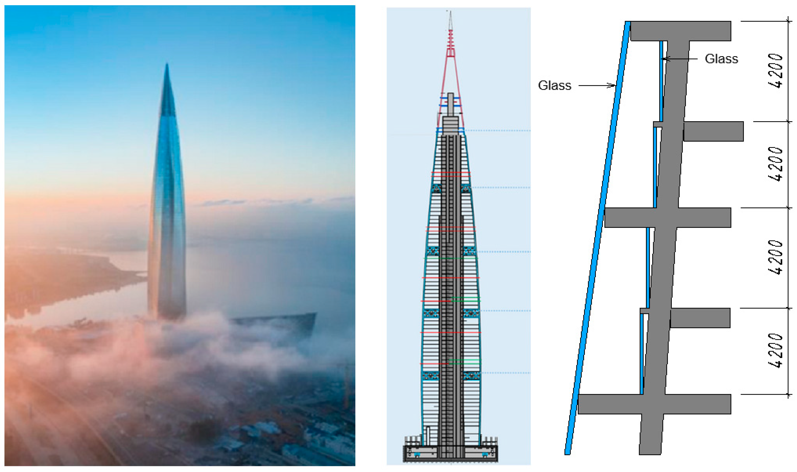
  145. Abdelrazaq, A.; Travush, V.; Shakhvorostov, A.; Timofeevich, A.; Desyatkin, M.; Jung, H. The Structural Engineering Design and Construction Of The Tallest Building In Europe Lakhta Center, St. Petersburg. Russia. Int. J. High-Rise Build. 2020, 9, 283–300. [Google Scholar] [CrossRef]
  146. Zhang, Y.; Zhang, Y.; Li, Z. A novel productive double skin façades for residential buildings: Concept, design and daylighting performance investigation. Build. Environ. 2022, 212, 108817. [Google Scholar] [CrossRef]
  147. Zhang, M.; Yang, Z.; Zhang, B.; Liu, T.; Yun, X. Analysis of intercondylar notch size and shape in patients with cyclops syndrome after anterior cruciate ligament reconstruction. J. Orthop. Surg. Res. 2021, 17, 23. [Google Scholar] [CrossRef] [PubMed]
  148. Chen, P.; Lin, X.; Chen, B.; Zheng, K.; Lin, C.; Yu, B.; Lin, F. The global state of research and trends in osteomyelitis from 2010 to 2019: A 10-year bibliometric analysis. Ann. Palliat. Med. 2021, 10, 3726–3738. [Google Scholar] [CrossRef]
  149. Ampese, L.C.; Sganzerla, W.G.; Di Domenico Ziero, H.; Mudhoo, A.; Martins, G.; Forster-Carneiro, T. Research progress, trends, and updates on anaerobic digestion technology: A bibliometric analysis. J. Clean. Prod. 2022, 331, 130004. [Google Scholar] [CrossRef]
  150. Ye, N.; Kueh, T.B.; Hou, L.; Liu, Y.; Yu, H. A bibliometric analysis of corporate social responsibility in sustainable development. J. Clean. Prod. 2020, 272, 122679. [Google Scholar] [CrossRef]
  151. Han, J.; Lu, L.; Yang, H. Numerical evaluation of the mixed convective heat transfer in a double-pane window integrated with see-through a-Si PV cells with low-e coatings. Appl. Energy 2010, 87, 3431–3437. [Google Scholar] [CrossRef]
Figure 1. Trombe’s wall modes: (a) winter night; (b) winter day; and, (c) summer day (data from ref. [34]).
Buildings 12 00366 g001
Figure 2. Zion National Park Visitor Center: (A) a general view of the building; (B) a sectional view of the Trombe wall (data from ref. [55,56]).
Buildings 12 00366 g002
Figure 3. Thermal distribution of the Trombe wall in December (data from ref. [55]).
Buildings 12 00366 g003
Figure 4. The classification and the use frequency of different phase changing materials types in various regions worldwide: (a) classification; (b) use frequency (data from ref. [67]).
Buildings 12 00366 g004
Figure 5. The Trombe–Michel wall (data from ref. [34]).
Buildings 12 00366 g005
Figure 6. The Trombe composite wall with PCM (data from ref. [70]).
Buildings 12 00366 g006
Figure 7. Schematic representation of the photocell Trombe wall (data from ref. [80,81]).
Buildings 12 00366 g007
Figure 8. Seasonal energy consumption during the cooling period (a) building cooling energy for the case with DL, (b) building cooling energy for the case with SL, (c) building peak power for the case with DL, (d) building peak power for the case with SL (reprinted from [105]).
Buildings 12 00366 g008aBuildings 12 00366 g008b
Figure 9. Scheme of double-skin façade operation (a) mode A, (b) mode B, (c) mode C, (d) mode D (data from ref. [34,106,107]).
Buildings 12 00366 g009
Figure 10. Classification of the DSF according to internal geometry: (a) box; (b) shaft-box; (c) corridor; (d) multi-storey (data from ref. [107,108,109,110,111,112]).
Buildings 12 00366 g010
Figure 11. Movable shading devices: (a) model of the façade element in winter and summer; (b) experimental installation (data from ref. [96]).
Buildings 12 00366 g011
Figure 12. CFD modeling as studied (reprinted from [119]): vertical temperature distribution on the inner façade.
Buildings 12 00366 g012
Figure 13. PV electrical produced energy assessment: (a) PV Yearly electrical produced energy—DL; (b) PV Yearly electrical produced energy—SL (reprinted from [105]).
Buildings 12 00366 g013
Figure 14. DSF scheme (data from ref. [127]).
Buildings 12 00366 g014
Figure 15. Schematic diagram of an installation for comparing a classic insulating glass unit and an insulating glass unit with phase-change materials (data from ref. [132,135]).
Buildings 12 00366 g015
Figure 16. Changes in the aggregate state and transparency of wax in the façade (data from ref. [136]).
Buildings 12 00366 g016
Figure 17. A scheme of glazed offices integrated with PV module (a) with PCM, (b) without PCM (data from ref. [136]).
Buildings 12 00366 g017
Figure 18. Lakhta Center (data from ref. [145]).
Buildings 12 00366 g018
Figure 19. Productive double façade concept: (a) General view of the building; (b) Structural section (data from ref. [146]).
Buildings 12 00366 g019
Figure 20. The network map of keyphrases (accessed on 21 January 2022).
Buildings 12 00366 g020
Figure 21. Modern keyword clusters for climate-adaptive façades (a) renewable energy, (b) heat flux, (c) phase-change material, (d) Mediterranean climate (accessed on 21 January 2022).
Buildings 12 00366 g021
Figure 22. Bibliometric analysis of authors.
Buildings 12 00366 g022
Figure 23. Co-authorship network of countries.
Buildings 12 00366 g023
Figure 24. Publications by subject area (accessed on 21 January 2022).
Buildings 12 00366 g024
Figure 25. Benchmarking the publication year and scholarly output (accessed on 21 January 2022).
Buildings 12 00366 g025
Figure 26. Benchmarking the publication year and field-weighted citation impact (accessed on 21 January 2022).
Buildings 12 00366 g026
Figure 27. Benchmarking the publication year and output in top 10% citation percentiles (field-weighted, %) (accessed on 21 January 2022).
Buildings 12 00366 g027
Figure 28. Benchmarking the Publication Year and Publications in Top 25% Journal Percentiles by CiteScore Percentile (%) (accessed on 21 January 2022).
Buildings 12 00366 g028
Table 1. Comparison of wall characteristics.
ParametersConcreteHydrated SaltParaffin
The room temperature, °C15–2518–2215–25
Changes in wall temperature at night, °C1–34–63–7
Changes in wall temperature during the day, °C7–1510–1810–22
Wall thickness, m0.20.080.05
Table 2. Comparison of Trombe wall and the double-skin façade.
ParametersTrombe WallDouble-Skin Façade
Air chamber width, mm20–35020–2000
Type of main part of the wall The masonryGlass
Number of operating modes of the structure3
(Figure 1)
5
(Figure 9) + Closed cavity
Research in climatic zones of KöppenAf, Bwh, Cfa, Cfb, Csb, Csa, Cwb, Dsb, DscBwh, Cfa, Cfb, Csa, Csb, Cwa, Dfb
Reduce energy costs by incorporating phase-change materials into the construction18.79–55.15%20–55%
Reduce energy costs by incorporating photovoltaic panels/cells into the construction65.2%57%
Study/application in high-rise constructionNoYes
Table 3. Main indicators of the theme (accessed on 21 January 2022).
Indicator ValueNote
Scholarly Output491Number of publications
(Year range: 2016 to 2021)
Citation Count4.689Number of citations received by
publications in Climate-adaptive
façades
Outputs in Top 10% Citation Percentiles (field-weighted)70 (14.3%)Number of publications in the top 10%
most-cited publications worldwide
Publications in Top Journal Percentiles by CiteScore Percentile162 (36.4%)Number of publications in the top 10%
journals by CiteScore
International Collaboration26.3%Publications co-authored with Institutions in other countries/regions
Table 4. Top Institutions (accessed on 21 January 2022).
InstitutionCountryScholarly
Output
Views
Count
Field-Weighted
Citation Impact
(Excl. Self-Citations)
Citation
Count (Excl.
Self-Citations)
1University of Science and Technology of ChinaChina249691.63488
2Hunan UniversityChina1910882.04508
3Hefei University of TechnologyChina167561.93453
4Norwegian University of Science and
Technology
Norway136010.91148
5Royal Melbourne Institute of Technology
University
Australia135252.13135
6Ministry of Education, ChinaChina105011.55147
7Hong Kong Polytechnic UniversityHong Kong96993.21377
8Islamic Azad UniversityIran84520.4100
9Ministry of Higher Education and
Scientific Research
Iraq81901.1660
10Northern Technical UniversityIraq81901.1660
224Peter the Great St. Petersburg Polytechnic UniversityRussia1600.511
Table 5. Systematization of the obtained results.
ReferenceConstruction TypeLocationClimateYearSubject of StudyType of ExperimentResults
[45]TWHuitzilac, Toluca (Mexico)Cwb2016The insolation of a conventional TWMathematical, SimulationThe loss of thermal energy from the sun through the translucent outer wall is about 60%. The maximum stored energy from the sun per day is about 109 MJ.
[58]TWLondon (the United Kingdom)Cfb2012Aerogel applicationMathematical,
Experimental
The authors considered aerogel as a filler for polycarbonate panels used in the TW.
Up to 60% efficiency and 4.5 years payback possible with optimized manifold coated with 10 mm granular aerogel
[59]TWSaudi ArabiaBwh2021Application of Carbon Nanotube (CNT) FluidMathematical,
Simulation
The addition of nanoparticles and an increase in the height of the TW significantly increase heat transfer and affect the flow structure and temperature field.
[73]TWBaghdad (Iraq)Bwh2009PCM applicationMathematical,
Simulation
The wall of the room using 8 cm thick PCM material (hydrated salt) is able to maintain a comfortable temperature with the least fluctuations
[77]TWParis, Lyon and Nice (France)Cfa
Csb
Csa
2020PCM applicationSimulationThe resulting heating demand in the bedroom by using the TW with PCM was reduced by 18.79% in Paris, 19.56% in Lyon, and 55.15% in Nice compared to the reference configuration.
[79]TWKansas City, USACfa2013Location of PCM layerSimulation,
Experimental
The optimal location of the PCM layer is a distance of 1/5 L from the inner surface of the wall. L is the thickness of the insulating cavity.
[80]TWPerak (Malaysia)Af2015Influence of different types of glazing on the TW with PVMathematical,
Simulation
Argon-filled double glass has shown significant results in reducing the cooling load and increasing the efficiency of photovoltaic panels. Double pane and double pane filled with argon at 1.5 m/s airflows is preferable to single pane in terms of energy efficiency
[86]TWHefei City
(China)
Cfa2017PV lamellasExperimentalAn angle of 50° is preferred for tilting PV lamellas in the TW.
This structure’s heat gain and power generation is 14.5% higher than the classical structure, where the PV is attached to the outside, and 14.1% compared to the structure, where the PV is attached to a massive wall.
[87]TWShanghai
(China)
Cfa2019Influence of the width of the channel in the wall with PVMathematical,
Simulation
As the channel width increased, natural convective heat transfer increased, and the PV surface was better cooled by air. For ventilation, the optimal duct size is: (b/H)opt = 1/5
[88]TWHefei (China)Cfa2019PV applicationMathematical,
Simulation, Experimental
The average thermal efficiency of the TW with PV was 65.2% higher than that of the classic TW system
[100]DSFHong Kong
(China)
Cfa2009Influence of different configurations and glazingMathematical,
Simulation, Experimental
DSF with single inner glazing and double reflective outer glazing can provide annual building cooling energy savings of approximately 26% compared to a conventional façade.
[112]DSFPorto (Portugal)Csb2017Influence of geometry and configurationMathematical,
Simulation
A multi-story DSF saves an average of 30% of the energy required for HVAC.
[113]DSFDelft (The Netherlands)Cfb2005Influence of plants on shadingMathematical,
Simulation, Experimental
Plants create a more effective shading system than blinds. The temperatures of the DSF layers are lower than with conventional shading. The plant’s temperature never exceeded 35 °C, while the blinds could exceed 55 °C.
[120]DSFBarcelona (Spain)Csa2015Influence of Venetian blindsMathematical,
Simulation
Venetian blinds can reduce solar heat gain by up to 35% in DSF
[122]DSFChangsha (China)Cfa2017PV lamellasMathematical,
Experimental
DSF with PV shading devices can save about 12.16% energy in summer compared to DSF with conventional shading blinds and 25.57% without them.
[132]DSFTorino (Italy)Cfa2014PCM glazing systemsExperimentalPCM glass helps to protect the building from overheating in summer. PCM glazing has a good ability to accumulate solar energy. The PCM prototype reduces energy gain by more than 50% compared to traditional windows in summer.
[136]DSFVenice (Italy), Helsinki (Finland) and Abu Dhabi (United Arab of EmiratesCfa
Dfb
Bwh
2016Using PV and PCM at the same timeMathematicalThe use of a PCM layer in the DSF cavity in combination with a translucent PV layer results in a reduction in the monthly cooling energy requirement in the range of 20–30%. The production of electrical energy increases by 5–8%.
[139]DSFJeddah, Abha,
Tabuk
(Saudi Arabia)
Bwh
Cwa
Bwh
2022Using PCMSimulationDSF with PCM in cold regions is much less effective than in the tropics. The use of DSF with PCM in Jeddah reduces the amount of energy required by 11.5% during the cold months of the year and by 5.6% during the warm months compared to a simple façade.
[142]DSFAversa (Italy)Csa2021Application PVC-coated polyester fabricMathematical,
Simulation, Experimental
Using the material as a second layer reduces the need for PES to 6.1% and also reduces the need for cooling energy to 29.3%.
Publisher’s Note: MDPI stays neutral with regard to jurisdictional claims in published maps and institutional affiliations.

