Article

Contemporary and Novel Hold-Down Solutions for Mass Timber Shear Walls

1
Wood Innovation Research Laboratory, School of Engineering, University of Northern British Columbia, Prince George, BC V2N 4Z9, Canada
2
Sustainable Engineered Structural Solutions Laboratory, Wood Science, University of British Columbia, Vancouver, BC V6T 1Z4, Canada
*
Author to whom correspondence should be addressed.
Buildings 2022, 12(2), 202; https://doi.org/10.3390/buildings12020202
Submission received: 9 January 2022 / Revised: 3 February 2022 / Accepted: 6 February 2022 / Published: 11 February 2022
(This article belongs to the Special Issue Buildings: 10th Anniversary)

Abstract

:
‘Mass timber’ engineered wood products in general, and cross-laminated timber in particular, are gaining popularity in residential, non-residential, as well as mid- and high-rise structural applications. These applications include lateral force-resisting systems, such as shear walls. The prospect of building larger and taller timber buildings creates structural design challenges; one of them being that lateral forces from wind and earthquakes are larger and create higher demands on the ‘hold-downs’ in shear wall buildings. These demands are multiple: strength to resist loads, lateral stiffness to minimize deflections and damage, as well as deformation compatibility to accommodate the desired system rocking behaviour during an earthquake. In this paper, contemporary and novel hold-down solutions for mass timber shear walls are presented and discussed, including recent research on internal-perforated steel plates fastened with self-drilling dowels, hyperelastic rubber pads with steel rods, and high-strength hold-downs with self-tapping screws.

1. Introduction

1.1. Mass Timber Construction

Growing environmental concerns and emphasis on resource efficiency, combined with the need to mitigate the impacts from urban population growth, renewed the interest to use the renewable material wood for non-residential and tall buildings [1]. Recent developments of innovative materials, connectors, and systems contributed to a resurgence in the use of wood as a structural material. On the material level, the introduction of cross-laminated timber (CLT), a plate-type engineered wood product which can be used in structural wall or floor assemblies, has been labelled a ‘game changer’ [2]. A landmark on the connection level was the establishment of self-tapping screws (STS) as the state of the art in wood connector technology [3]. Finally, on the systems level, the concept of hybrid structures, which integrate wood with different materials to form a system that makes use of each material’s strength and stiffness and overcomes their individual weaknesses, offers great potential to overcome the current height limitations of timber-only buildings [4]. Publications, such as Technical Guide for the Design and Construction of Tall Wood Buildings [5] and Use of Timber in Tall Multi-Storey Buildings [6] and recently built examples from around the world (e.g., [7,8,9,10]) show that wood has the potential to expand into construction segments that are the traditional stronghold of steel and concrete.
Mass timber products in general, and CLT in particular, provide architects and engineers with opportunities to expand the use of wood in structures beyond low- and mid-rise residential construction. Compared with traditional lumber products with small cross sections, engineered mass timber panels offer better fire resistance, homogeneity in mechanical properties, and dimensional stability when exposed to changes in environmental conditions [11]. The high in-plane strength and stiffness of CLT panels make them suitable for diaphragms or shear walls as part of the lateral force-resisting system (LFRS), even in earthquake-prone regions [12]. Compared with steel and concrete buildings, buildings with wood LFRS are lighter and attract lower seismic loads; however, they are usually more flexible and more vulnerable against overturning forces [13].

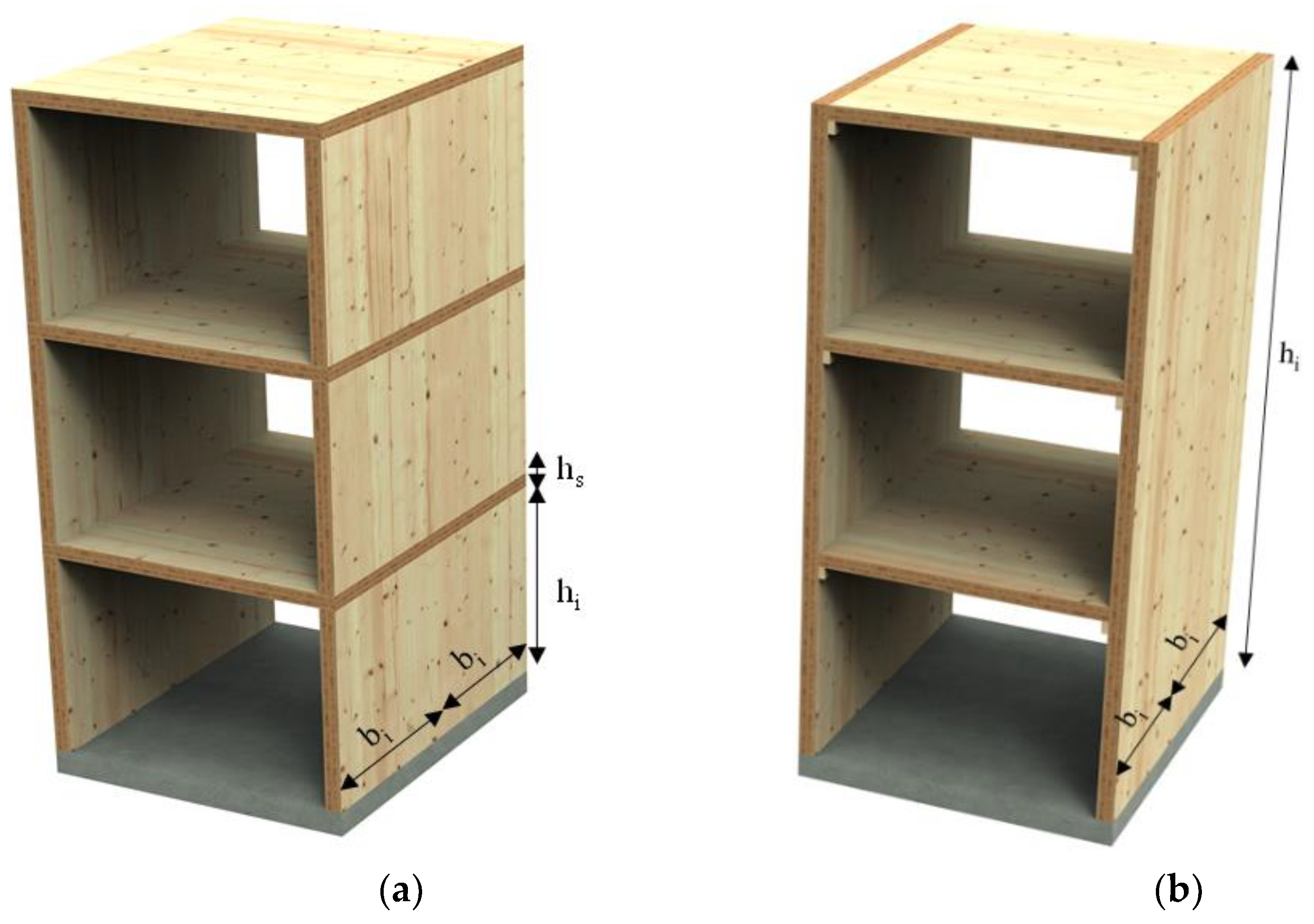
1.2. Mass Timber Shear Walls

In North America, based on the current state of knowledge, mass timber structures have been incorporated into the (unpublished) 2020 National Building Code of Canada (NBCC) [14] for gravity-load systems in buildings up to 12 stories, and the 2021 International Building Code [15] for gravity-load systems in buildings up to 18 stories. In addition, the NBCC 2020 will adopt CLT shear walls as seismic LFRS and refers to the Canadian Standard for Engineering Design in Wood (CSA O86) [16] for detailing provisions intended to ensure that rocking is the energy dissipative kinematic mechanism.
These design provisions are tailored to platform-type construction, illustrated in Figure 1a, where each floor acts as a platform for the floor above. The walls at each floor act as an independent rocking system with connections to the floor below; vertical joints connect the individual panels within the wall assembly [17]. Platform-type construction requires a large number of panels to be handled on-site, and a large number of connections between panels and floors, hold-down (HD) deformations accumulate at each level, as do the compression perpendicular to grain stresses on the floor panels. In contrast, balloon-type shear wall systems consist of continuous panels over multiple floors, with the intermediate floors framing into their face (Figure 1b). This construction type eliminates perpendicular to grain bearing between floors, provides walls with slender panel aspect ratios, and requires fewer HD and shear bracket connections over the height of a building [17]. To date, however, only limited research is available on the seismic performance of balloon-type CLT construction (e.g., [18]), and implementation of standardized design provisions is still outstanding.
In platform-type structures, connections to the floor below are provided with brackets and HDs to resist sliding and (uplift), respectively. The vertical wall panel-to-panel connections typically use plywood splines or half-lap joints (Figure 2). The latter components are usually designed to provide ductility and energy dissipation [19,20]. The research findings on platform-type CLT shear walls (e.g., [21,22]) can be summarized as follows: (1) Their structural performance in terms of strength, stiffness, ductility, and energy dissipation is governed by the connections; (2) adequate seismic performance and ductile behaviour can be achieved with proper detailing; (3) rocking kinematic motion is preferred to dissipate the energy; (4) the CLT wall panel deformation is negligible under in-plane lateral loading.

1.3. Objectives

HD solutions—when designed elastically and installed at both top and bottom of the panels—ensure continuity in the transfer of the load to the foundation, allow activating the energy-dissipative function of the vertical joint connections, and—when designed for this purpose—add ductility and energy dissipation to the LFRS through plastic failure in the fasteners. The objectives of this paper are to summarize the state of the art in HD technology for mass timber shear walls and present recent research on novel HD solutions.

2. Contemporary and Novel Hold-Down Solutions

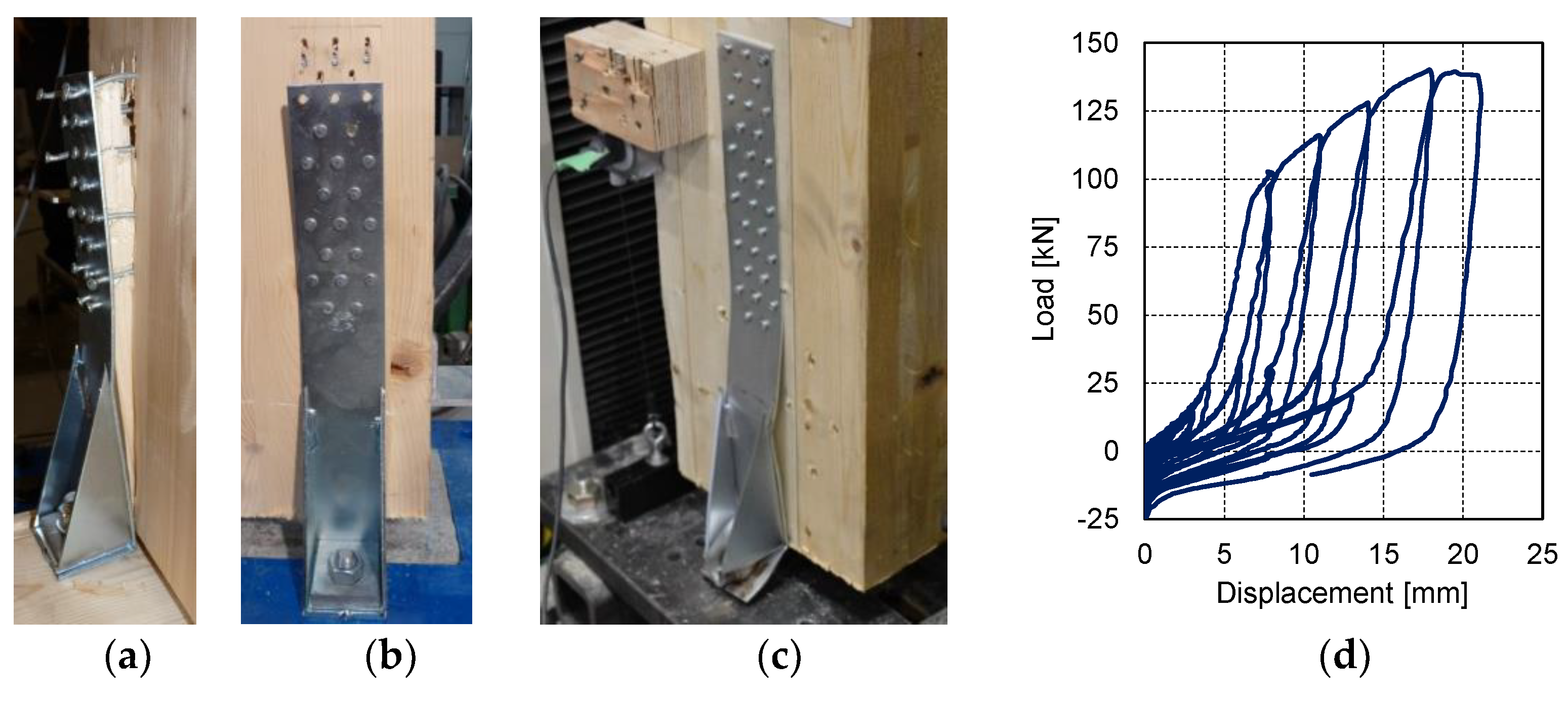
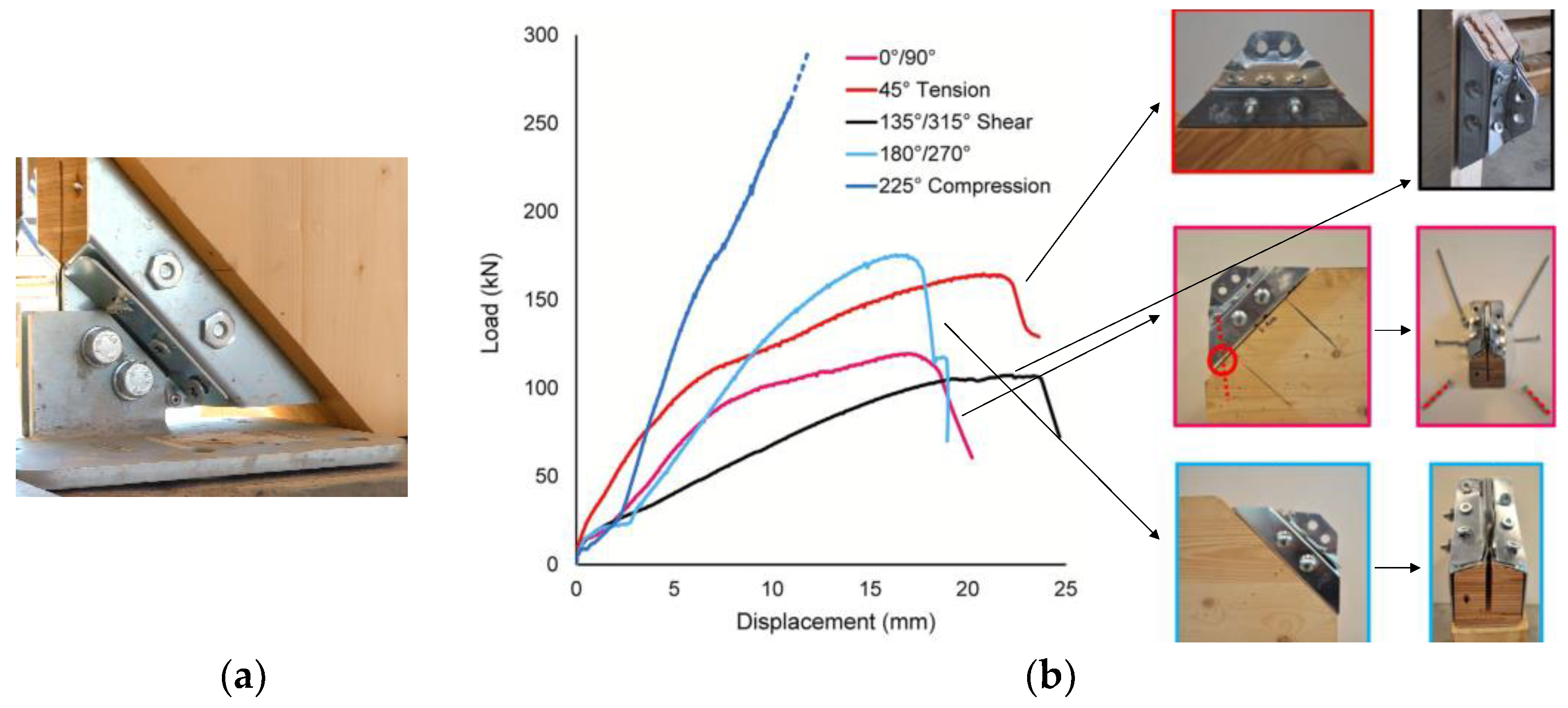
2.1. Nailed Steel Brackets

Early studies by Ceccotti et al. [23] were pivotal to establishing connection details for CLT shear walls anchored using light steel plates nailed to the panels. Subsequent research formed the basis of the design of HDs and brackets to prevent wall uplift and sliding at its base [24]. Conventional metal cold-shaped HDs were proven adequate for low-rise buildings [25,26] when accepting a certain degree of damage in the joints and residual deformation in the timber assembly. Figure 3a,b show typical failures of commercially available non-resilient bracket connectors under reversed cyclic loading. Although the HD was designed for the required strength, the lack of resilience may result in local brittle wood failure. With such designs, the connection cannot be restored, and replacement could become uneconomic. Larger steel straps with an increased number of nails can provide higher strength and stiffness and shift the failure mode into the strap (Figure 3c); however, such HDs, when insufficiently sized, have been shown to be prone to high strength degradation under cyclic loading, particularly buckling [27]. The uplift force–displacement curve, shown in Figure 3d, illustrates the typical pinching behaviour of nailed HDs with significant loss of stiffness in unloading under reversed-cyclic loads.

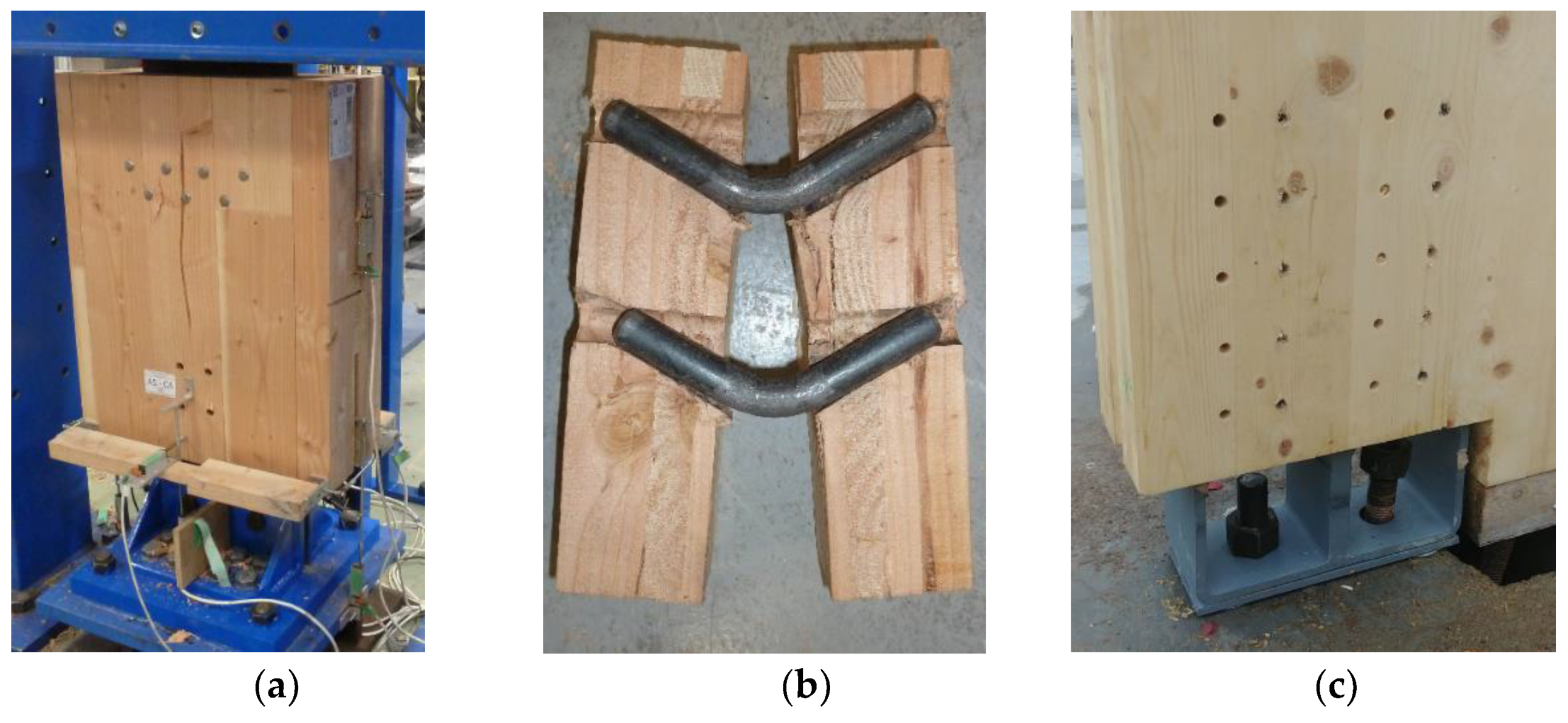
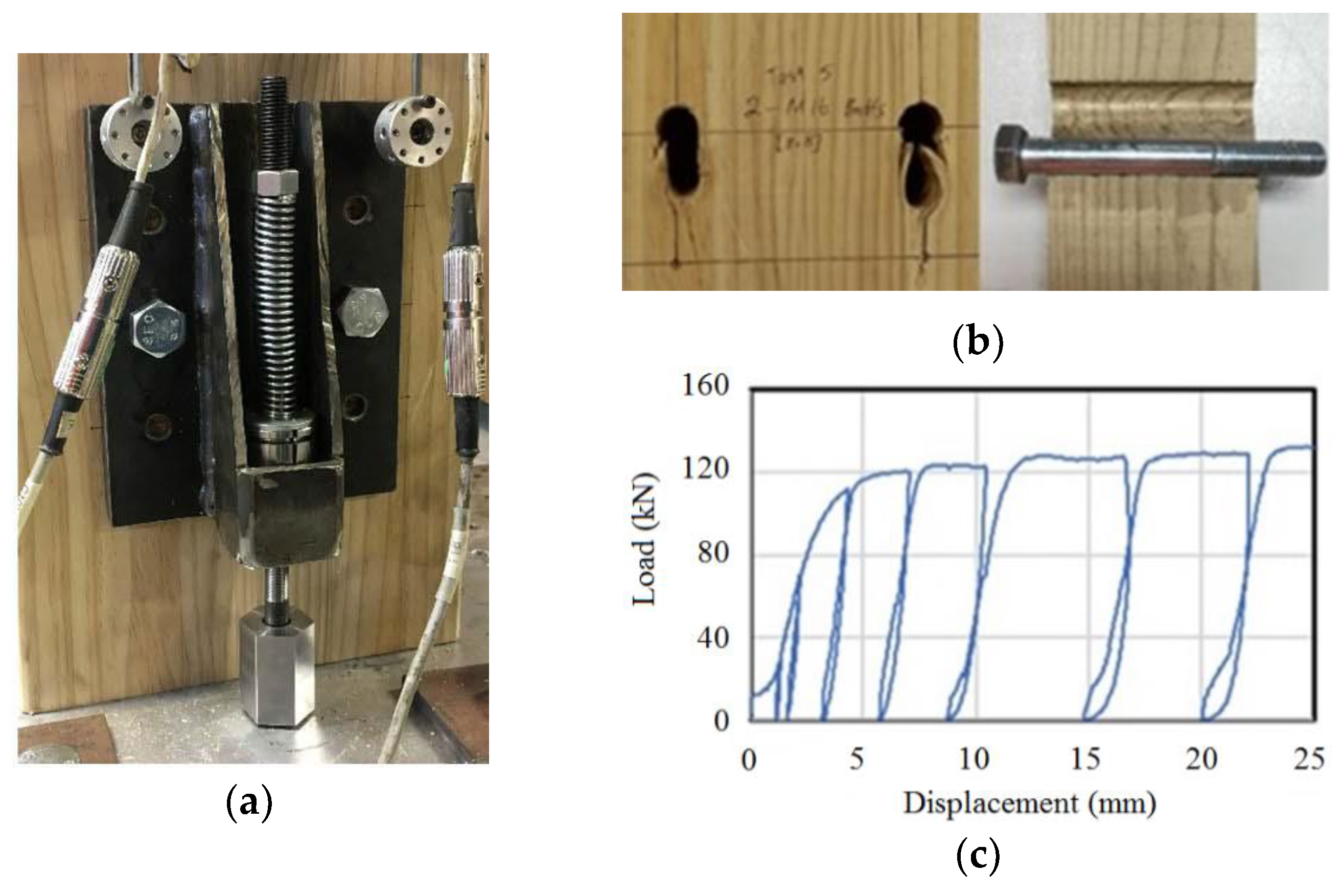
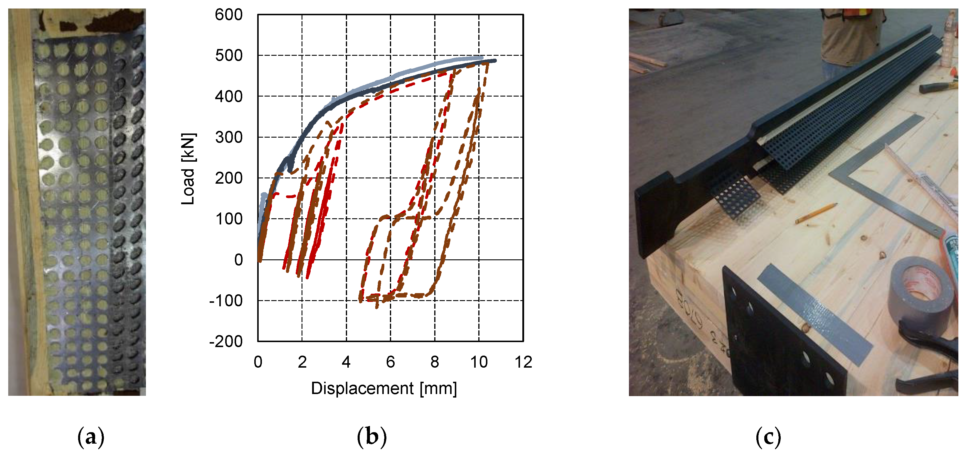
2.2. Dowelled Slotted-In Steel Plates

Dowelled slotted-in steel plates, varying the fastener spacing and the loaded end distance, were studied as HDs for mass timber shear walls [28,29,30]. It was possible to design large-scale HDs with ductile behaviour, as shown in Figure 4b; however, brittle wood failure (tear-out) was observed in some tests. It was also observed that ductility increased with the row spacing and end distance of fasteners; however, dimension constraints have to be observed when placing HDs close to the wall corner. Reinforcements using STS around the HDs were shown effective to reduce the likelihood of brittle failure and increase strength and ductility. However, the deformations developed through the yielding of steel and wood crushing, with permanent damage in the CLT panels and fasteners, require repair of dowelled slotted-in steel plates HDs after major earthquakes. HD ductility significantly increased when the out-of-plane opening of CLT lamellas was inhibited using bolted threaded rods. The behaviour of dowelled slotted-in steel plates in multiple-shear arrangements was studied [31], including sequential failure modes of the fasteners and detailing, to reduce the opening up of the side layers in the timber member. This type of HD is being applied in practice; an example (Begbie Elementary school in Vancouver, Canada) is shown in Figure 4c.

2.3. Pinching-Free Connectors

Pinching-free connectors (PFCs) were proposed as alternative HD-to-timber connections with slender fasteners, with the aim to eliminate the loss of stiffness in unloading under reversed-cyclic loads [32]. PFCs were designed using stocky fasteners and steel side plates; the latter were held down using a spring-type system, as shown in Figure 5a. The result is a ratcheting system in which each fastener remains elastic, while wall deformation is dictated by spring elongation. Regardless of uplift displacement demand in the HD, the ratcheting system ensures a perpetual surface contact between the fastener and wood element. Plastic deformation develops only through embedment in wood (Figure 5b), leading to better accuracy in predicting the behaviour of connectors. PFCs were also found to be effective in reducing peak deformation when compared with the conventional connectors, beyond 50% lower, with negligible pinching [32] (Figure 5c).

2.4. X-RAD System

The proprietary X-RAD system [33] was developed to connect CLT panels at their corners and to the foundation using steel plates, such as L-shape profiles (Figure 6a). X-Rad connectors have a hardwood block encased in a cold-formed metal box, machined to accommodate six STS, installed at two angles of inclination to capture shear forces and tension and ensure reliable stress flow into the CLT elements [34]. Experimental campaigns characterized the mechanical behaviour of the X-RAD connection under monotonic and cyclic loading [34]. From the observed failure modes, shown in Figure 6b, together with typical force–displacement curves, the first yielding of ductile members occurred; the system ultimately collapsed due to the block-shear failure mode of the internal plate. Experimental behaviour of X-RAD loaded in tension showed a static ductility of 6 or higher, making it suitable when used as dissipative HD connectors in CLT shear walls [35].

2.5. Holz–Stahl–Komposit System

The proprietary Holz–Stahl–Komposit (HSK) system [36], originally developed for Glulam member connections, was modified in its layout for use as HD for CLT shear walls [37]. The HSK system is based on adhesively bonded perforated steel plates, inserted inside precut slots in the mass timber panels. The system’s strength, stiffness, and ductility are governed by the steel plate material properties, while the adhesive bond and mass timber panel are capacity protected and designed to remain free of damage. From a design perspective, research showed that ductile failure modes develop when plastic behaviour in predefined ductile zones is observed, leaving all timber elements undamaged [38] (Figure 7a). The uplift load–displacement curves exhibited significant permanent deformations after each loading cycle (Figure 7b). The system has been successfully implemented in the Wood Innovation Design Centre in Prince George, Canada (Figure 7c).

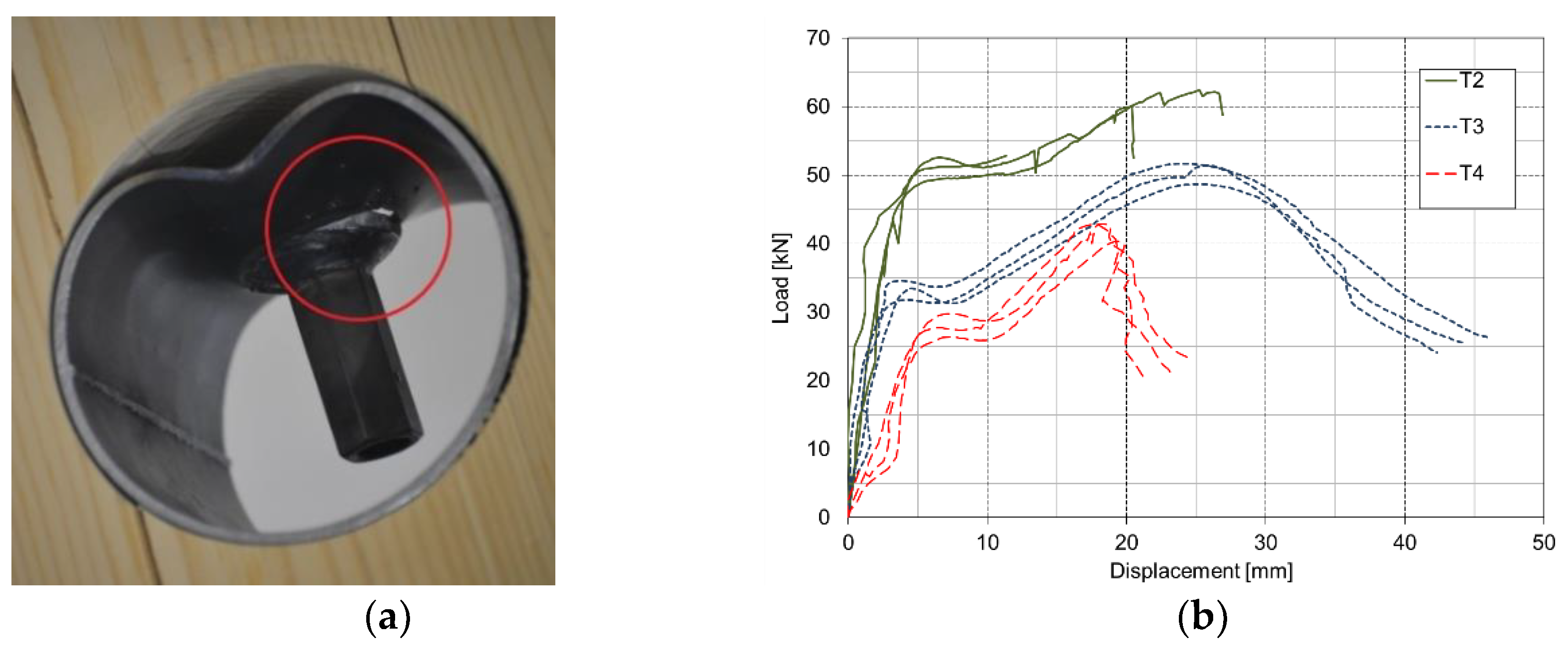
2.6. Internal Hollow Steel Tubes

Internal-bearing connections can minimize the risk of brittle failure in CLT panels; a noteworthy HD solution applying this concept consists of hollow steel tubes embedded into CLT panels [26,39]. The detailing consists of welding a coupler to the top of the tube, placing the tube into a panel hole of the same diameter, and attaching a tie-down steel rod to the coupler as an anchor to the floor below (Figure 8a). The components are reasonably easy to install, can be readily inspected, and can potentially be replaced.
Experimental investigations indicated that this HD, when installed in CLT shear walls, could avoid damage to the wood and brittle failure (Figure 8a). While the ultimate failure exhibited undesirable buckling of the steel tube, the concept of an internal load-bearing mechanism was deemed the main advantage since the CLT panel was not damaged at all. Resulting load–displacement curves using three different diameters (T2 = 50.8 mm, T3 = 76.2 mm, and T4 = 101.6 mm) are illustrated in Figure 8b. Subsequent numerical work optimized the steel tube connector geometry for a target load of 90 kN [40]. To explore the steel tube as a viable HD solution for tall buildings and higher demands, it was proposed to employ two or three steel tubes in a group.

2.7. Slip–Friction Devices

Slip–friction devices, consisting of a steel plate encased in the timber element and two built-in side steel plates held together with bolts and disc springs, were proposed as HD for mass timber shear walls [41]. Friction is developed at the contact surfaces between the steel plates. A stable, symmetric friction–slip behaviour was shown with the use of abrasive-resistant steel as slotted plates and mild steel for side plates. High dissipation energy capability can be attained in the system without pinching. Friction–slip connections made of abrasive-resistant steel as slotted plates and mild steel for side plates studied in [42] showed better performance than those using brass shims, having behaviour not affected by the loading rate. The experiments on rigid shear walls equipped with symmetric friction–slip joints further showed that connection with high slot lengths (slippage length) tended to exhibit self-centring behaviour [42].
CLT shear-walls equipped with slip–friction joints as HD displayed the desired flag-shaped hysteretic behaviour, shown in Figure 9b, although exhibiting limited self-centring capabilities [43]. Slip-friction connectors were further advanced into resilient slip friction (RSF) connectors [44,45] which provide a damage-free self-centring solution for CLT shear walls, avoiding downtime and repair costs due to earthquakes. In the RSF device, the two cap plates and two slotted plates assure elastic–plastic behaviour of the joint, while bolts and Belleville washers are used to create a controlled pressure between the plates. The self-centring capacity is enabled by the zigzag-like connection interface between the cap and slotted plates (Figure 9a). Nonlinear time–time history analyses showed that buildings with RSF HD exhibited low damage during moderate-to-severe seismic events [46]. The system, commercialized under the name ‘Tectonus’, has been used in recent structures such as the Fast + Epp building in Vancouver (Figure 9c).

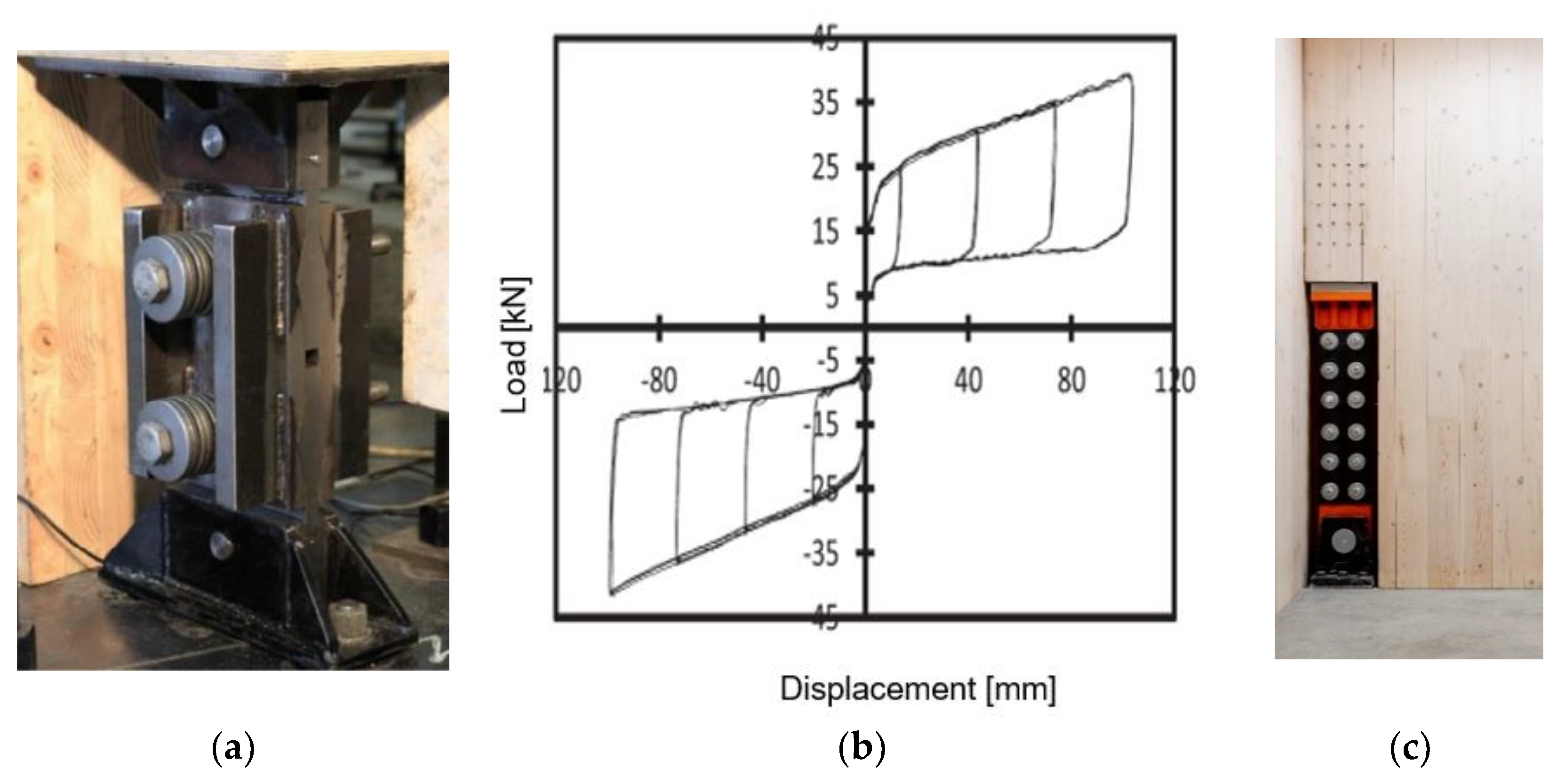
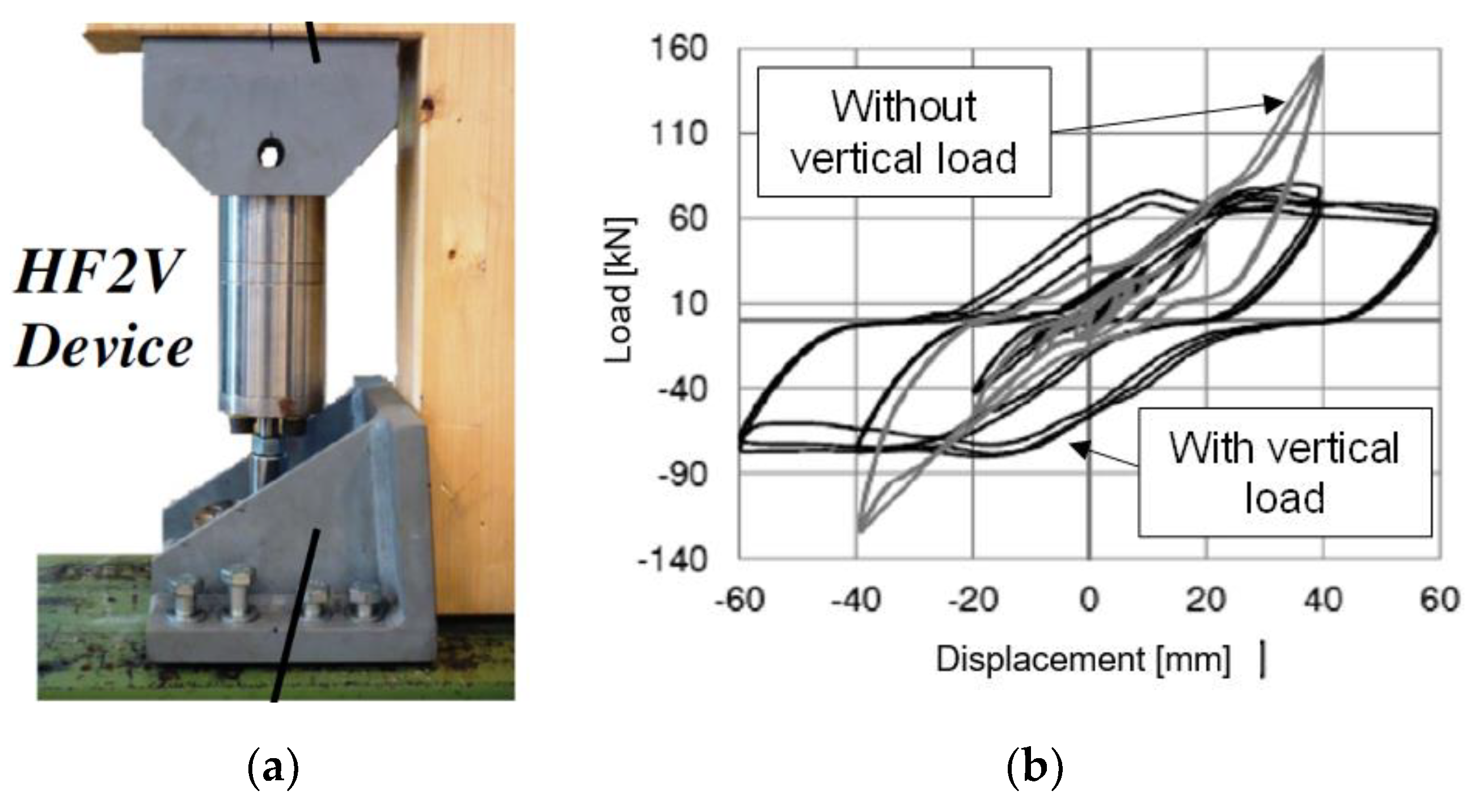
2.8. Volume Damping Devices

Damper-based HDs were studied with a focus on glulam walls anchored at their base, using high-force-to-volume damping devices (HF2VDDs) made of a steel shaft sliding within a tube [47,48] (Figure 10a). The damping and energy dissipation are provided by an extruded lead mounted around the shaft. System-scale wall tests were performed on glulam shear walls with HF2VDD HDs installed using inclined self-tapping screws and anchored to the foundation through bolts. Tested full-scale specimens confirmed that such walls can exhibit a high level of energy dissipation with low pinching. Severe crushing at the panel base laid on the plate foundation was observed, indicating a need for reinforcements in wood.

2.9. Self-Tapping Screw Connections

Recent research at the Wood Innovation Research Laboratory (WIRL) at the University of Northern British Columbia (UNBC) investigated CLT shear walls with STS connections as HD, shear bracket, and panel-to-panel connection. The objective was to determine the strength, stiffness, and ductility of a rocking wall system as a function of the number of STS in these connections. Component level connection tests (Figure 11a) and full-scale shear wall tests were conducted. HDs were tested with two (HD-2), six (HD-6), and nine (HD-9) screws. Quasi-static monotonic and reversed cyclic tests were conducted. The typical HD failure mode (fastener yielding) is illustrated in Figure 11b. The corresponding hysteresis behaviour of the HD connections, combined with a representative monotonic curve, presented in Figure 11c, showed nonlinear behaviour in terms of degradation and pinching. Until capacity, the HD showed little stiffness degradation; beyond capacity, distinct degradation in cyclic reloading stiffness was observed.
As expected, strength was a linear function of the number of STS. The average strength values for HD-6 and HD-9 were about 3.1 and 4.5 times those for HD-2, under the monotonic tests. Similar trends were observed in yield strength. The elastic stiffness increased with the number of screws: HD-6 and HD-9 were about 2.5 and 5 times stiffer than HD-2. HDs with fewer screws showed higher ductility, e.g., the ductility of HD-2 was 42% and 16% higher than HD-6 and HD-9 under monotonic loading, and 79% and 47% higher under cyclic loading. Most importantly, the results corresponded to those of previous research [49] confirming that STS in energy-dissipative connections are severely overdesigned and are likely to remain elastic during seismic design level events. Based on these results, there is a clear need to better define the relevant design parameters for the use of STS in energy-dissipative connections. Designers should consult with manufacturers about the availability of test data.

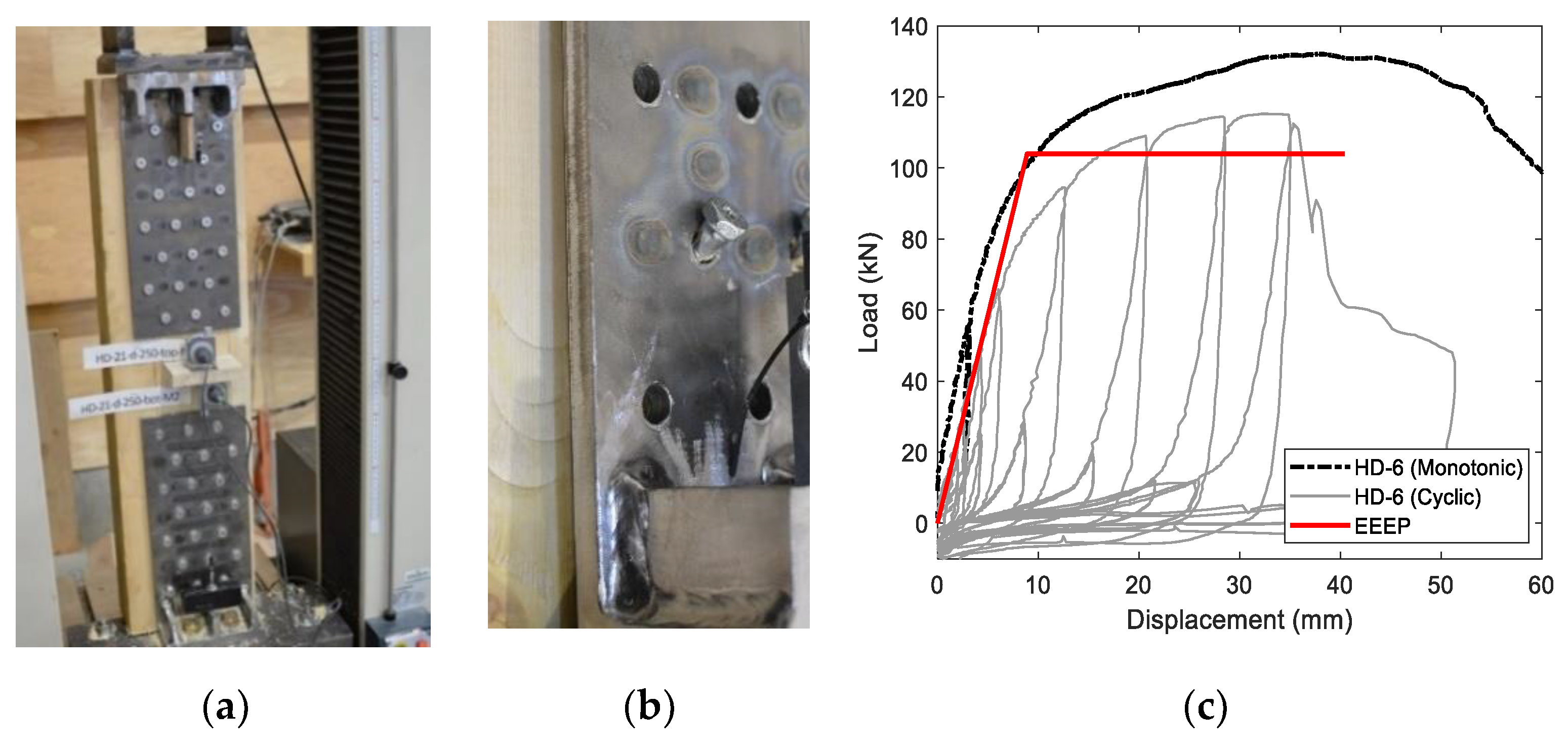
2.10. Internal Perforated Steel Plates

Timber connections combining slotted-in steel-plates with dowel-type fasteners avoid the use of adhesives [50] and, when combined with perforated steel plates, can also avoid the common dowel yielding and wood crushing failure mechanisms. Research on perforated steel plates as end-brace connections in timber frames [51,52] and as base shear connectors in CLT shear walls [53] verified their suitability as energy-dissipative components. As an alternative to common dowels, self-drilling dowels (SDDs) can simplify the installation and allow drilling through the whole assembly, including the steel plate, without predrilling [54]. If SDD connections are combined with internal-perforated steel plates (IPSPs) and designed with sufficient overstrength, then the desired ductility can be achieved through plate yielding [55]. The viability of using IPSPs with SDDs was demonstrated at the material and component levels. Different steel plate geometries were studied, and the most important parameter was found to be perforation length, with longer perforations exhibiting larger deformation capacity but being weaker and less stiff [56].
Recent research at the UNBC investigated HDs with IPSPs and SDDs. The objective was to determine the strength, stiffness, and ductility of a rocking wall system while designing the SDD connections with sufficient overstrength so that all energy dissipated was concentrated by the steel plates. IPSPs were welded to L-shaped steel profiles (Figure 12a). Then, IPSPs were inserted into 5 mm by 150 mm slots in the middle layer of the CLT, and eight 7 mm × 133 mm SDDs were used to fasten the IPSPs. One monotonic test and three half-cyclic tests were conducted. The hold-downs failed by yielding the steel ‘bridges’, as shown in Figure 12a, the HD uplift force–displacement curves are illustrated in Figure 12b. After an initial stiff and linear phase, the steel plates started deforming, with a pronounced drop in stiffness. The cyclic HD force–displacement hysteretic curves showed stiffness degradation per cycle, the load consistently increased until ultimate capacity was reached, and after the subsequent cycle, the specimens failed.

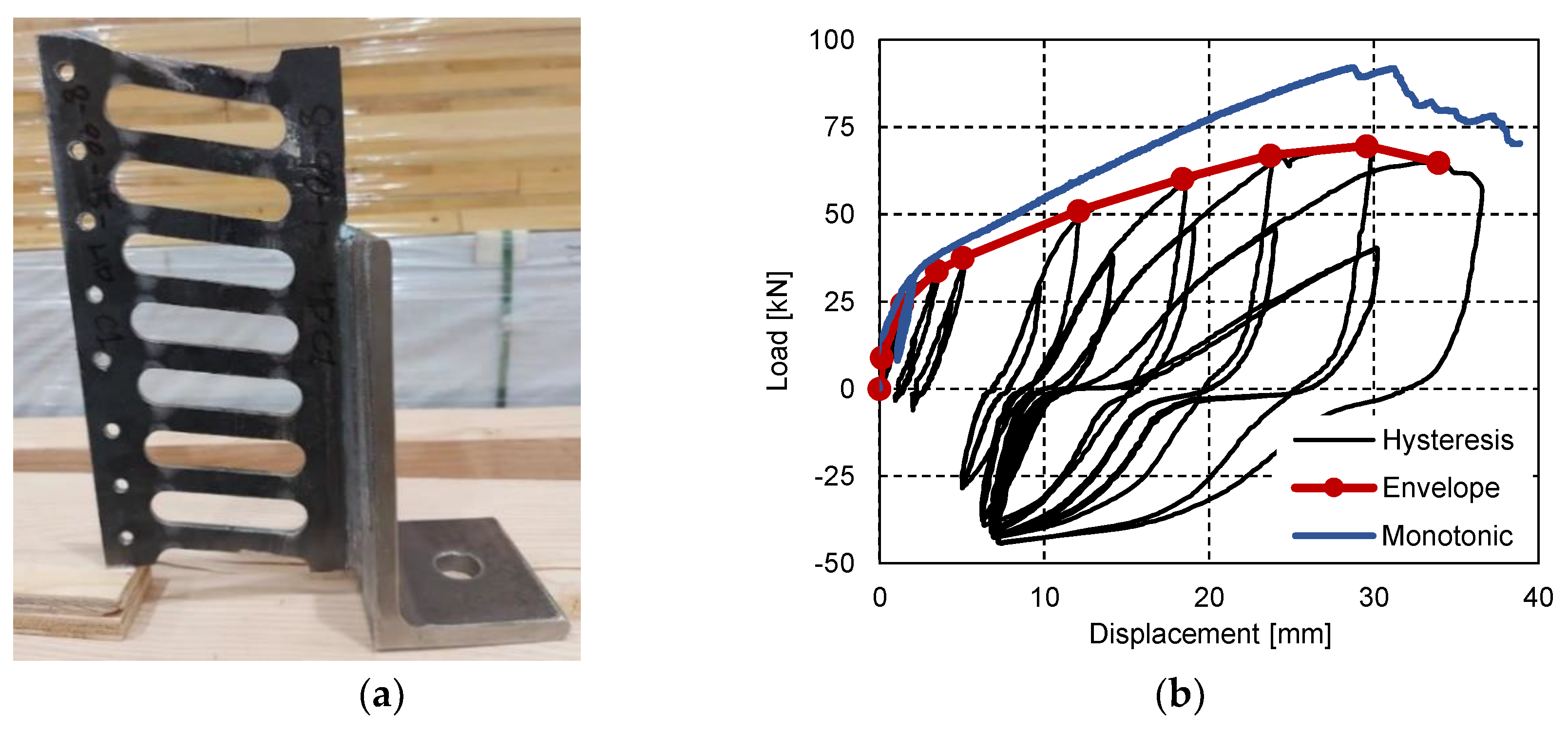
2.11. Hyperelastic Pads with Internal Steel Rods

In 2019, capacity design principles for CLT shear walls were introduced into CSA O86, specifying that ‘Energy dissipative connection shall be designed to ensure that all principle inelastic deformations and all principle energy dissipation occurs in: (a) connections between vertical joints of adjacent shearwall segments; and (b) shear connections of shearwalls to foundations or floors underneath, in uplift only.’ While no specific definitions are provided for ‘principle inelastic deformations and principle energy dissipation’, HDs have to be interpreted as nondissipative connections which shall be capacity protected by designing them to remain elastic under the force and displacement demands that are induced in them when the energy-dissipative connections reach the 95th percentile of their ultimate resistance. To comply with these Canadian design provisions (it is beyond the scope of this paper to discuss how meaningful these provisions are, and how likely they are to be changed again), there is a need to develop HD solutions with high load-carrying and deformation capacities while remaining elastic.
A material with such properties is hyperelastic rubber; therefore, it can be considered as a potential HD solution for CLT shear walls. The structural performance of internal-bearing hyperelastic HD for CLT shear walls was evaluated by Asgari et al. [57]. The components of the HD include the elastomeric bearing layers, steel plates, and a steel rod with nuts, as illustrated in Figure 13a. Recent research at the UNBC investigated CLT shear walls with hyperelastic pads and internal steel rods as HD. The objective was to determine the strength, stiffness, and ductility of a rocking wall system, where all energy dissipation occurs in the vertical panel-to-panel connections. Herein, only the HD tests, conducted to determine their performance parameters for the shear wall design, are presented and discussed. The rubber’s effective compressive mechanical properties as functions of shape factor and loading speed and its load–displacement behaviour under quasistatic monotonic, repeated serviceability, and reversed cyclic loading for a given target load, herein 120 kN, were investigated [58]. The performance of a hyperelastic HD (Figure 13b) demonstrated that the assembly can achieve the performance to remain elastic. Ductile HD failure can be achieved as long as the steel rod is the weakest link in the setup. However, all other members must be capacity protected to avoid brittle failure. In further research [58], the performance of a hyperelastic HD was investigated at the component level, with different sizes of rubber pads. The tests demonstrated that (1) the HD can remain elastic under rocking kinematics provided that the elastic limit of the steel rod is not exceeded; (2) failure of the rod is the subsequent desired ductile mode; (3) sufficient CLT width can prevent undesired brittle failure mode before steel yielding; (4) increasing the rubber pad thickness reduces the HD stiffness; (5) increasing the rubber pad width increases the HD stiffness. Based on the results of the investigations presented herein, a capacity-design procedure for the hyper-elastic hold-downs was proposed.

3. Discussion

The prospect of building larger and taller timber buildings creates higher demands on the ‘hold-downs’ in shear wall buildings. These demands are multiple: strength to resist loads, stiffness to minimize deflections during wind events, as well as deformation compatibility to facilitate the desired rocking motion during an earthquake.
Contemporary and novel hold-down solutions for mass timber shear walls were presented herein. Metal cold-shaped HDs attached with nails or screws were proven adequate for low-rise buildings when accepting a certain degree of damage in the joints and residual deformation in the timber assembly. It was shown that dowelled slotted-in steel plates can provide large-scale HDs with ductile behaviour, with high strength and stiffness; however, brittle CLT failure (tear-out) has to be prevented with sufficient spacing or wood reinforcements. HDs that rely on fastener yielding and wood crushing to dissipate energy exhibit pronounced pinching behaviour. Pinching-free HD connectors were developed to eliminate the loss of stiffness in unloading under reversed-cyclic loads, relying on a ratcheting system where the fasteners remain elastic, while wall deformation is dictated by the spring elongation. Larger capacities can be achieved using the proprietary X-RAD system in which CLT panels are connected at their corners and to the foundation, using customized steel plates. While the yielding of ductile steel members is the first failure mode, the system ultimately collapses due to the block-shear failure mode of the CLT panel. The proprietary HSK system, based on adhesively bonded perforated steel plates, inserted inside precut slots, avoids any exterior penetration of the mass timber panels. Ductile failure modes develop in predefined steel zones, and damage to the timber is avoided.
Internal-bearing connections can minimize the risk of brittle wood failure; a noteworthy HD solution applying this concept consists of hollow steel tubes embedded into CLT panels. The concept of an internal load-bearing mechanism was deemed the main advantage since the CLT panel was not damaged at all. Slip–friction devices, consisting of a steel plate encased in the timber element and two built-in side steel plates held together with bolts and disc springs, provide a stable, symmetric, pinching-free, and flag-shaped hysteretic behaviour, with high-dissipation energy capability. Slip–friction connectors were further advanced into resilient slip–friction connectors, which provide a damage-free self-centring solution for CLT shear walls. Damper-based HDs, made of a steel shaft sliding within a tube, provide a high level of energy dissipation with low pinching. Recent research investigated internal-perforated steel plates fastened with self-drilling dowels, hyperelastic rubber pads with steel rods, and high-strength STS assemblies.
The findings from the latter studies are of particular interest, as STSs are now considered the state-of-the-art approach in mass timber construction [3,59]. In platform-type construction, a capacity design philosophy is normally employed to avoid brittle wood failure modes and system collapse. The dissipative components are designed to be ductile, while the nondissipative components are overdesigned [12,60]. Current design practices designate the (nailed or screwed) shear connections between coupled CLT shear wall panels as the primary energy-dissipative components; these connections are designed using established procedures, including standardized modification factors. The UNBC research confirmed previous findings [49] regarding the inherent conservatism in these standardized design procedures with STS connections being up to six times stronger than their calculated design values. As a consequence, these energy-dissipating connections may remain elastic during seismic events, resulting in a much stiffer LFRS than assumed when estimating the overall structural behaviour. Based on these results, there is a clear need for further research to better define the relevant design parameters for the use of STS in energy-dissipative connections. Designers should consult with manufacturers about the availability of test data. Recent (e.g., [60]) and ongoing research in this area focuses on developing capacity-based procedures such that energy dissipation occurs in designated connections in the desired sequence, while brittle elements remain elastic. Such procedures will provide design guidance so that structural engineers beyond the early adaptors become confident in utilizing the renewable resource wood in their projects.

Author Contributions

Conceptualization, data curation, funding acquisition, investigation, writing—original draft preparation, T.T.; writing—review and editing, C.L. All authors have read and agreed to the published version of the manuscript.

Funding

The research conducted at the UNBC was supported by the Government of British Columbia through a BC Innovate Ignite grant and an FII Wood First grant to Dr. Tannert.

Data Availability Statement

The data presented from the UNBC research are available on request from the corresponding author.

Acknowledgments

The support provided by the UNBC technicians Michael Billups, James Andal, and Ryan Stern, the undergraduate research assistants Anthony Bilodeau and Maxym Maj, and the graduate research assistants, Max Drexler, Hosein Asgari, Ajibola Oyawoye, and Selamawit Dege Dires, is greatly appreciated.

Conflicts of Interest

The author declares no conflict of interest.

References

  1. Green, M.; Karsh, J.E. Tall Wood—The Case for Tall Wood Buildings; Wood Enterprise Coalition: Vancouver, BC, Canada, 2012. [Google Scholar]
  2. Karacabeyli, E.; Gagnon, S. Cross-Laminated Timber (CLT) Handbook; FPInnovations: Vancouver, BC, Canada, 2019. [Google Scholar]
  3. Dietsch, P.; Brandner, R. Self-tapping screws and threaded rods as reinforcement for structural timber elements–A state-of-the-art report. Constr. Build. Mater. 2015, 97, 78–89. [Google Scholar] [CrossRef]
  4. Pan, Y.; Tannert, T.; Kaushik, K.; Xiong, H.; Ventura, C. Seismic Performance of a Proposed Wood-Concrete Hybrid System for High-rise Buildings. Eng. Struct. 2021, 238, 112194. [Google Scholar] [CrossRef]
  5. Karacabeyli, E.; Lum, C. Technical Guide for the Design and Construction of Tall Wood Buildings in Canada; Special Publication (SP-55E); FPInnovations: Vancouver, BC, Canada, 2014. [Google Scholar]
  6. Smith, I.; Frangi, A. Use of Timber in Tall Multi-Storey Buildings; SED 13; IABSE: Zurich, Switzerland, 2014; ISBN 978-3-85748-133-8. [Google Scholar]
  7. Malo, K.A.; Abrahamsen, R.B.; Bjertnæs, M.A. Some structural design issues of the 14-story timber framed building ‘Treet’ in Norway. Eur. J. Wood Wood Prod. 2016, 74, 407–424. [Google Scholar] [CrossRef] [Green Version]
  8. Woschitz, R.; Zotter, J. High-rise timber building HoHo Vienna–The structural concept. Österr. Ing. Archit. Z. 2017, 162, 63–68. [Google Scholar]
  9. Connolly, T.; Loss, C.; Iqbal, A.; Tannert, T. Feasibility Study of Mass-Timber Cores for the UBC Tall Wood Building. Buildings 2018, 8, 98. [Google Scholar] [CrossRef] [Green Version]
  10. Staub-French, S.; Pilon, A.; Poirier, E.; Teshnizi, Z.; Fallahi, A.; Moudgil, M.; Tannert, T.; Froese, T. Design Process Innovation on Brock Commons Tallwood House. Constr. Innov. 2021, 22, 23–40. [Google Scholar]
  11. Brandner, R.; Flatscher, G.; Ringhofer, A.; Schickhofer, G.; Thiel, A. Cross laminated timber: Overview and development. Eur. J. Wood Prod. 2016, 74, 331–351. [Google Scholar] [CrossRef]
  12. Tannert, T.; Follesa, M.; Fragiacomo, M.; González, P.; Isoda, H.; Moroder, D.; Xiong, H.; van de Lindt, J.W. Seismic Design of CLT Buildings. Wood Fiber Sci. 2018, 50, 3–26. [Google Scholar] [CrossRef] [Green Version]
  13. Loss, C.; Tannert, T.; Tesfamariam, S. State-of-the-art review of displacement-based seismic design of timber buildings. Constr. Build. Mater. 2018, 191, 481–497. [Google Scholar] [CrossRef]
  14. National Research Council Canada. NBCC—National Building Code of Canada; National Research Council Canada: Ottawa, ON, Canada, 2020.
  15. International Code Council, Inc. IBC—International Building Code; International Code Council, Inc.: Washington, DC, USA, 2021. [Google Scholar]
  16. CSA Group. CSA O86—Engineering Design in Wood; CSA Group: Mississauga, ON, Canada, 2019. [Google Scholar]
  17. Shahnewaz, M.; Dickof, C.; Tannert, T. Seismic Behaviour of Balloon Frame CLT Shearwalls with Different Ledgers. ASCE J. Struct. Eng. 2021, 147, 04021137. [Google Scholar] [CrossRef]
  18. Chen, Z.; Popovski, M. Mechanics-based analytical models for balloon-type cross-laminated timber (CLT) shear walls under lateral loads. Eng. Struct. 2019, 208, 109916. [Google Scholar] [CrossRef]
  19. Shen, Y.; Schneider, J.; Tesfamariam, S.; Stiemer, S.F.; Chen, Z. Cyclic behavior of bracket connections for cross-laminated timber (CLT): Assessment and comparison of experimental and numerical models studies. J. Build. Eng. 2021, 39, 102197. [Google Scholar] [CrossRef]
  20. Jalilifar, E.; Koliou, M.; Pang, W. Experimental and Numerical Characterization of Monotonic and Cyclic Performance of Cross-Laminated Timber Dowel-Type Connections. J. Struct. Eng. 2021, 147, 04021102. [Google Scholar] [CrossRef]
  21. Nolet, V.; Casagrande, D.; Doudak, G. Multipanel CLT shearwalls: An analytical methodology to predict the elastic-plastic behavior. Eng. Struct. 2019, 179, 640–654. [Google Scholar] [CrossRef]
  22. Deng, P.; Pei, S.; van de Lindt, J.W.; Amini, M.O.; Liu, H. Lateral behavior of panelized CLT walls: A pushover analysis based on minimal resistance assumption. Eng. Struct. 2019, 191, 469–478. [Google Scholar] [CrossRef]
  23. Ceccotti, A.; Sandhaas, C.; Okabe, M.; Yasumura, M.; Minowa, C.; Kawai, N. SOFIE project—3D shaking table test on a seven-storey full-scale cross-laminated timber building. Earthq. Eng. Struct. Dyn. 2013, 42, 2003–2021. [Google Scholar] [CrossRef]
  24. Dujic, B.; Aicher, S.; Zarnic, R. Investigation on in-plane loaded wooden elements—Influence of loading on boundary conditions. Otto Graf J. 2005, 16, 259–272. [Google Scholar]
  25. Popovski, M.; Pei, S.; van de Lindt, J.W.; Karacabeyli, E. Force modification factors for CLT structures for NBCC. In Materials and Joints in Timber Structures; RILEM Bookseries 9; Aicher, S., Reinhardt, H.W., Garrecht, H., Eds.; Springer: Dordrecht, The Netherlands, 2014; pp. 543–553. [Google Scholar]
  26. Schneider, J. Conventional and novel timber steel hybrid connections: Testing, performance and assessment. Ph.D. Thesis, University of British Columbia, Vancouver, BC, Canada, 2015. [Google Scholar]
  27. Benedetti, F.; Rosales, V.; Opazo-Vega, A.; Norambuena-Contreras, J.; Jara-Cisterna, A. Experimental and numerical evaluation of hold-down connections on radiata pine Cross-Laminated-Timber shear walls: A case study in Chile. Eur. J. Wood Wood Prod. 2019, 77, 79–92. [Google Scholar] [CrossRef]
  28. Ottenhaus, L.-M.; Li, M.; Smith, T.; Quenneville, P. Mode Cross-Over and Ductility of Dowelled LVL and CLT Connections under Monotonic and Cyclic Loading. J. Struct. Eng. 2018, 144, 04018074. [Google Scholar] [CrossRef]
  29. Ottenhaus, L.-M.; Li, M.; Smith, T. Structural performance of large-scale dowelled CLT connections under monotonic and cyclic loading. Eng. Struct. 2018, 176, 41–48. [Google Scholar] [CrossRef]
  30. Brown, J.R.; Li, M. Structural performance of dowelled cross-laminated timber hold-down connections with increased row spacing and end distance. Constr. Build. Mater. 2021, 271, 121595. [Google Scholar] [CrossRef]
  31. Bocquet, J.-F.; Epinal, F.; Lemaître, R.; Bader, T.K. Design recommendations and example calculations for dowel-type connections with multiple shear planes. Des. Connect. Timber Struct. 2018, 241, 241–295. [Google Scholar]
  32. Chan, N.; Hashemi, A.; Zarnani, P.; Quenneville, P. Pinching-Free Connector for Timber Structures. J. Struct. Eng. 2021, 147, 04021036. [Google Scholar] [CrossRef]
  33. RothoBlaas. X-RAD Manual; RB: Cortaccia, Bolzano, Italy, 2018. [Google Scholar]
  34. Polastri, A.; Giongo, I.; Piazza, M. An innovative connection system for CLT structures. Struct. Eng. Int. 2017, 27, 502–511. [Google Scholar] [CrossRef]
  35. Polastri, A.; Giongo, I.; Angeli, A.; Brandner, R. Mechanical characterization of a prefabricated connection system for Cross Laminated Timber structures in seismic regions. Eng. Struct. 2018, 167, 705–715. [Google Scholar] [CrossRef]
  36. Bathon, L.; Bletz-Mühldorfer, O.; Schmidt, J.; Diehl, F. Fatigue performance of adhesive connections for wooden wind towers. In Joints in Timber Structures; Springer: Dordrecht, The Netherlands, 2014; Volume 9, pp. 375–380. [Google Scholar]
  37. Zhang, X. Seismic design of timber steel hybrid high-rise buildings. Ph.D. Thesis, University of British Columbia, Vancouver, BC, Canada, 2017. [Google Scholar]
  38. Zhang, X.; Popovski, M.; Tannert, T. High-capacity hold-down for mass-timber buildings. Constr. Build. Mater. 2018, 164, 688–703. [Google Scholar] [CrossRef]
  39. Schneider, J.; Tannert, T.; Tesfamariam, S.; Stiemer, S.F. Experimental assessment of a novel steel tube connector in cross-laminated timber. Eng. Struct. 2018, 177, 283–290. [Google Scholar] [CrossRef]
  40. Mpidi Bita, H.; Tannert, T. Numerical Optimisation of Novel Connection for Cross-Laminated Timber Buildings. Eng. Struct. 2018, 175, 273–283. [Google Scholar] [CrossRef]
  41. Loo, W.Y.; Quenneville, P.; Chouw, N. A numerical study of the seismic behaviour of timber shear walls with slip-friction connectors. Eng. Struct. 2012, 34, 233–243. [Google Scholar] [CrossRef]
  42. Loo, W.Y.; Quenneville, P.; Chouw, N. A new type of symmetric slip-friction connector. J. Constr. Steel Res. 2014, 94, 11–22. [Google Scholar] [CrossRef]
  43. Hashemi, A.; Masoudnia, R.; Quenneville, P. Seismic performance of hybrid self-centring steel-timber rocking core walls with slip friction connections. J. Constr. Steel Res. 2016, 126, 201–213. [Google Scholar] [CrossRef]
  44. Hashemi, A.; Zarnani, P.; Masoudnia, R.; Quenneville, P. Seismic resistant rocking coupled walls with innovative Resilient Slip Friction (RSF) joints. J. Constr. Steel Res. 2017, 129, 215–226. [Google Scholar] [CrossRef]
  45. Hashemi, A.; Zarnani, P.; Masoudnia, R.; Quenneville, P. Experimental Testing of Rocking Cross-Laminated Timber Walls with Resilient Slip Friction Joints. J. Struct. Eng. 2018, 144, 04017180. [Google Scholar] [CrossRef]
  46. Hashemi, A.; Zarnani, P.; Quenneville, P. Earthquake resistant timber panelised structures with resilient connections. Structures 2020, 28, 225–234. [Google Scholar] [CrossRef]
  47. Wrzesniak, D.; Rodgers, G.W.; Fragiacomo, M.; Chase, J.G. Experimental testing of damage-resistant rocking glulam walls with lead extrusion dampers. Constr. Build. Mater. 2016, 102, 1145–1153. [Google Scholar] [CrossRef]
  48. Vishnupriya, V.; Rodgers, G.W.; Mander, J.B.; Chase, J.G. Precision Design Modelling of HF2V Devices. Structures 2018, 14, 243–250. [Google Scholar] [CrossRef]
  49. Sullivan, K.; Miller, T.H.; Gupta, R. Behavior of cross-laminated timber diaphragm connections with self-tapping screws. Eng. Struct. 2018, 168, 505–524. [Google Scholar] [CrossRef]
  50. Tuhkanen, E.; Ojamaa, M. Early experimental investigations on slotted-in steel plate connections with self-perforating dowels in CLT. Wood Mat. Sci. Eng. 2019, 16, 102–109. [Google Scholar] [CrossRef]
  51. Daneshvar, H.; Dickof, C.; Letarte, J.P.; Niederwestberg, J.; Spencer, J.; Chui, Y.H. Seismic performance of end brace connections in ductile braced timber frame. In Proceedings of the International Network on Timber Engineering Research (INTER), Tacoma, WA, USA, 26–29 August 2019. [Google Scholar]
  52. Dickof, C.; Jackson, R.; Daneshvar, H.; Niederwestberg, J.; Chui, Y.H. Perforated plates as dissipative connections in mass timber seismic force resisting systems. In Proceedings of the World Conference on Timber Engineering (WCTE), Santiago, Chile, 11–14 January 2021. [Google Scholar]
  53. Daneshvar, H.; Niederwestberg, J.; Letarte, J.-P.; Dickof, C.; Chui, Y.H. Seismic Performance of base shear connections in cross laminated timber shearwalls. In Proceedings of the World Conference on Timber Engineering (WCTE), Santiago, Chile, 11–14 January 2021. [Google Scholar]
  54. Dong, W.; Li, M.; He, M.; Li, Z. Experimental testing and analytical modeling of glulam moment connections with self-drilling dowels. J. Struct. Eng. 2021, 147, 04021047. [Google Scholar] [CrossRef]
  55. Nicolas, J.H. Pilot Study of a High Capacity Ductile Seismic Hold-Down for Cross-Laminated Timber. Master’s Thesis, Montana State University, Bozeman, MT, USA, 2019. [Google Scholar]
  56. Drexler, M.; Dires, S.; Tannert, T. Internal Perforated-steel-plate connections for CLT shear walls. In Proceedings of the World Conference on Timber Engineering, Santiago, Chile, 11–14 January 2021. [Google Scholar]
  57. Asgari, H.; Tannert, T.; Ebadi, M.M.; Loss, C.; Popovski, P. Hyperelastic hold-down solution for CLT shear walls. Constr. Build. Mater. 2021, 289, 123173. [Google Scholar] [CrossRef]
  58. Ajibola, O.A. High-capacity hyperelastic hold-down for cross-laminated timber shear walls. In Project Report; University of Northern British Columbia: Prince George, BC, Canada, 2021. [Google Scholar]
  59. Brown, J.R.; Li, M.; Tannert, T.; Moroder, D. Experimental study on orthogonal joints in cross-laminated timber with self-tapping screws installed with mixed angles. Eng. Struct. 2021, 228, 111560. [Google Scholar] [CrossRef]
  60. Casagrande, D.; Doudak, G.; Masroor, M. A proposal for capacity-based design of multi-storey CLT buildings. In Proceedings of the International Network on Timber Engineering Research (INTER), Online Conference, 16–19 August 2021. [Google Scholar]
Figure 1. Platform-type (a) and balloon-type (b) construction (schematic produced by Andrea Roncari (UBC student, reprinted with permission)).
Buildings 12 00202 g001
Figure 2. CLT shear wall connections (schematic produced by David Owolabi (UBC student, reprinted with permission)).
Buildings 12 00202 g002
Figure 3. Nailed HDs: (a) brittle wood failure; (b) nail yielding; (c) steel bracket yielding (photo credit: (a,b) Cristiano Loss; (c) Thomas Tannert); (d) uplift force–displacement behaviour.
Buildings 12 00202 g003
Figure 4. Dowelled slotted-in steel plates: (a) HD test setup; (b) ductile steel yielding and wood crushing failure modes (photo credit: (a,b) Justin Brown; (c) Fast + Epp, reprinted with permission).
Buildings 12 00202 g004
Figure 5. Pinching-free connectors: (a) as-built HD connector; (b) local failure with only crushing (photo credit: Nicholas Chan, reprinted with permission); (c) pinching-free load–displacement.
Buildings 12 00202 g005
Figure 6. X-RAD system: (a) HD connector (photo credit: Rothoblaas, reprinted with permission); (b) force–displacement curves and failure modes (photo credit: Andrea Polastri, reprinted with permission).
Buildings 12 00202 g006
Figure 7. HSK-based HD: (a) steel plate after testing; (b) uplift force–displacement curve; (c) installed HD (photo credit: (a), Xiaoyue Zhang; (c), Robert Malczyk, reprinted with permission).
Buildings 12 00202 g007
Figure 8. Steel tube HD: (a) typical failure (photo credit: Johannes Schneider, reprinted with permission); (b) load–displacement curves.
Buildings 12 00202 g008
Figure 9. RSF HD: (a) close-up view; (b) force–displacement (photo credit: Ashkan Hashemi, reprinted with permission); (c) commercial application (photo credit: Fast + Epp, reprinted with permission).
Buildings 12 00202 g009
Figure 10. Damper-based HD: (a) close-up view of the damper device (photo credit: Geoffrey Rodgers, reprinted with permission); (b) typical load–displacement curve.
Buildings 12 00202 g010
Figure 11. (a) HD with STS; (b) failure mode (photo credit: Thomas Tannert); (c) force–displacement curves.
Buildings 12 00202 g011
Figure 12. (a) Deformed HD with IBSP (photo credit: Thomas Tannert); (b) force–displacement curves.
Buildings 12 00202 g012
Figure 13. (a) Deformed HD (photo credit: Thomas Tannert); (b) force–displacement curves.
Buildings 12 00202 g013
Publisher’s Note: MDPI stays neutral with regard to jurisdictional claims in published maps and institutional affiliations.

