1. Introduction
At present, the seismic performance of reticulated shells has been systematically studied; however, the influences of roofing systems have been ignored in most studies. Research on the seismic performances of reticulated shells can be divided into the analysis of the seismic response and the analysis of the failure mechanism in response to strong earthquakes. Cao Zi et al. [
1] used mode superposition and response spectrum methods to analyse the seismic response of a single-layer reticulated shell and studied the influence of different spans and rise-to-span ratios on the internal seismic force coefficients of reticulated shell members. Lin Jiahao et al. [
2] summarised and compared seismic design methods for large span space structures and proposed applying the pseudo excitation method to analyse the seismic response of structures in the elastic stage. Fan Feng et al. [
3,
4] analysed the seismic performance of reticulated shell structures with semi-rigid joints in the elastic stage. To further analyse the nonlinear response of reticulated shells undergoing strong earthquakes, Shen Shizhao et al. [
5,
6,
7] examined the dynamic stability of reticulated shell structures and their failure mechanisms during strong earthquakes, proposed analysing the complete dynamic time history in the full load domain to investigate the seismic response of reticulated shell structures from the elastic stage to the failure stage, and identified typical strong earthquake failure modes and remediation methods for reticulated shell structures.
In recent years, scholars have begun to pay attention to the influence of roofing systems on the dynamic performance of large span space structures. Chen Yangji and Shen Zuyan [
8] analysed the seismic performance of grid structures with concrete roofing systems that did not have purlins, and they found that these roofing systems made important improvements in the fundamental frequencies of the structures and reduced the internal forces on grid members by approximately 60–75% during earthquakes. Koliou et al. [
9,
10,
11] examined the seismic responses and failure mechanisms when large span truss structures with enclosure components were exposed to strong earthquakes. They classified this type of building as a truss structure system composed of rigid walls and a flexible roof (RWFD), established a simplified two-dimensional finite element model (FEM) to analyse the RWFD structures and proposed a basic formula to estimate the period estimation and a method for the seismic design of RWFD structures. Cao Zhenggang et al. [
12] analysed the influence of metal roof panels on the seismic response of reticulated shell structures based on a reticulated shell structure in Shenbei New District (Shenyang, China) and found that the seismic failure load of a structure notably decreased after the addition of roof panels. Zhou Yizhe and Zhang Yigang [
13] used shaking table tests to analyse the influence of roofing systems on the seismic response of a cylindrical reticulated shell structure and found that the skin effect of a roofing system could improve its fundamental structural frequency and reduce its node acceleration response.
According to existing studies, roofing systems can improve the ability of large span space structures to bear an external load. Therefore, it is necessary to consider the influence of the roofing system on the seismic performance analysis of a single-layer spherical reticulated shell. However, there are additional deficiencies in the existing research. First, the authors used an inaccurate FEM to analyse a reticulated shell structure with a roofing system. In previous studies, the roof panel and reticulated shell members were connected by common nodes in the finite element analysis, which is inconsistent with the structural form of the roofing system in practical engineering, which consists of purlin, purlin hanger, pillar and roof panels. All of these components determine the influence mechanism of the roofing system on the seismic performance of spherical reticulated shells. Second, at present, scholars have not deeply analysed the mechanism of the influence of a roofing system on the seismic response of a shell, and they have not systematically investigated the influence of the parameters of shells and roofing systems on their seismic performance. In this paper, the finite element analysis method is applied to a single-layer spherical reticulated shell with a roofing system and verified by the experiment described in Ref. [
14]. Additionally, this paper investigates the influences of roofing systems on the natural vibration characteristics of shells, studies the seismic response of a shell with a roofing system and the mechanism of the influence of the roofing system on the shell under strong earthquake conditions, and studies the influence of different parameters of reticulated shells and roofing systems on the seismic performance.
2. Finite Element Model of a Shell with a Roofing System
2.1. Introduction of Finite Element Analysis Method
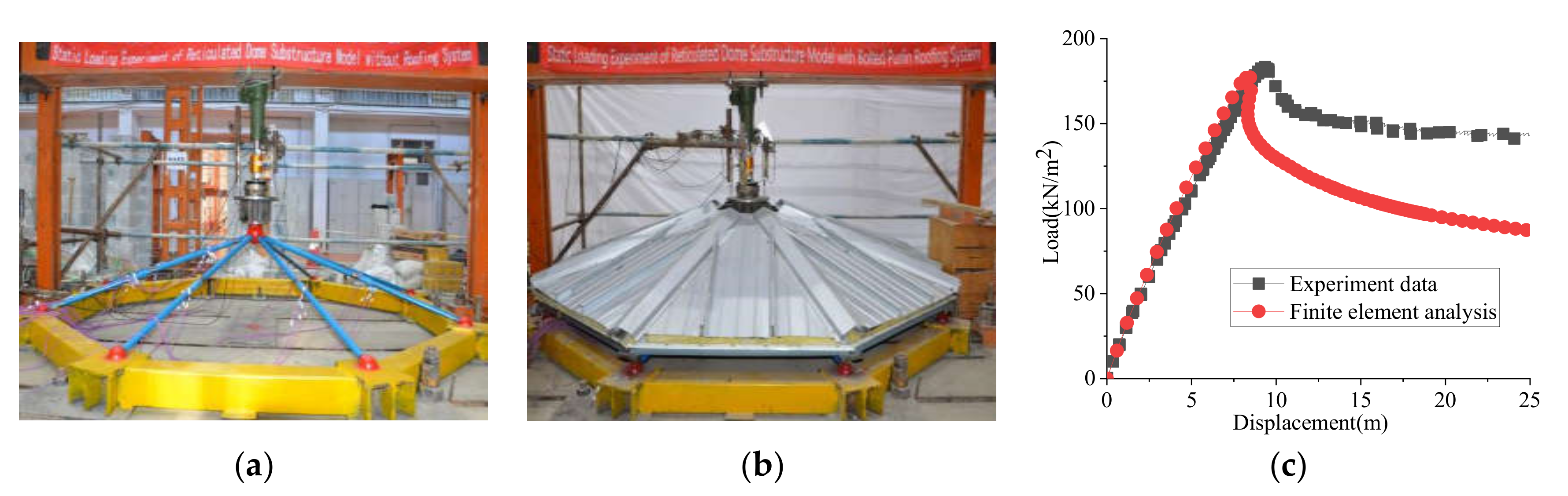
In previous studies [
14,
15], the authors established a finite element analysis method to study the static stability of a reticulated shell structure with a roofing system and verified the applicability of the method with a series of static loading experiments, as shown in
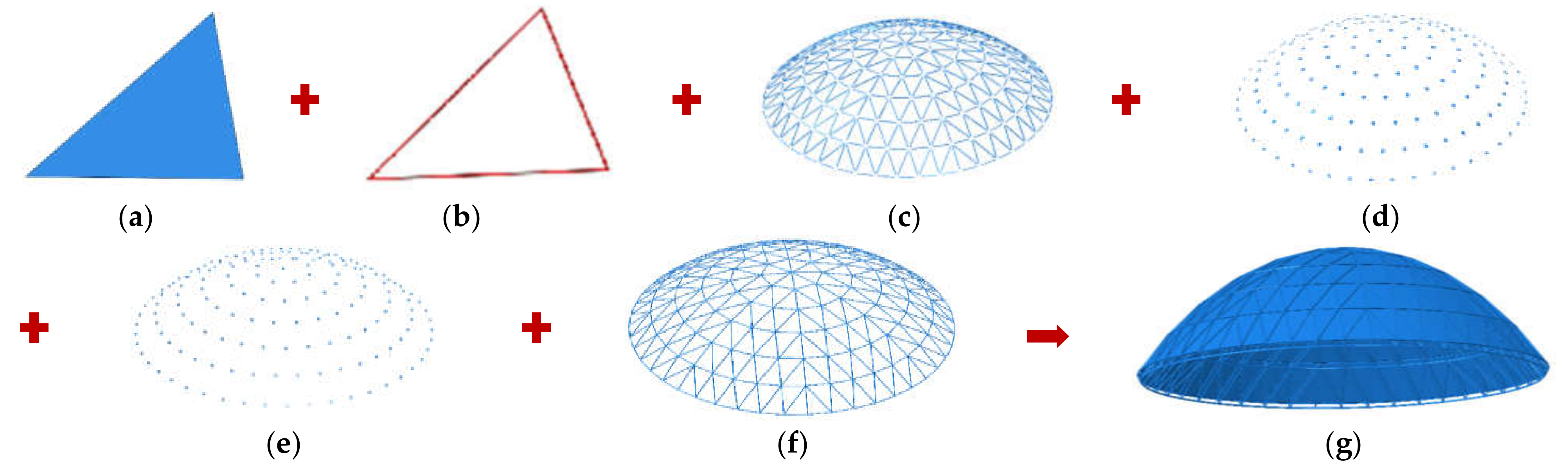
Figure 1. The finite element analysis considered the effects of purlins, semi-rigid purlin joints, orthotropic roof panels, and the strength and stiffness of the connections between roof panels and purlins, as shown in
Figure 2.
In the present study, the elastic modulus, yield strength and Poisson’s ratios of the equivalent orthotropic panel are obtained by deriving the orthotropic material properties of the steel roof panel profile. The material parameters of the weakened area between purlin and roof panel are obtained by tensile tests and a finite element analysis of the self-tapping screw connections between purlin and roof panel. In this paper, the constitutive model of steel is an ideal elastoplastic model; the elastic modulus and yield strength of steel are 206 GPa and 235 MPa, respectively, the material damping of steel is Rayleigh damping, and the damping ratio is 0.02. The nomenclature for shell D4073-W refers to the following: 40, span of the shell; 7, span-to-rise ratio of the shell; 3, roof load (3 × 60 kg/m2); W, shell without a roofing system; LSWM, bolted purlin roofing system; and HHWM, welded purlin roofing system.
2.2. Discussion of the Finite Element Analysis Method
The finite element analysis method in this paper is compared with the method in previous studies [
8,
12,
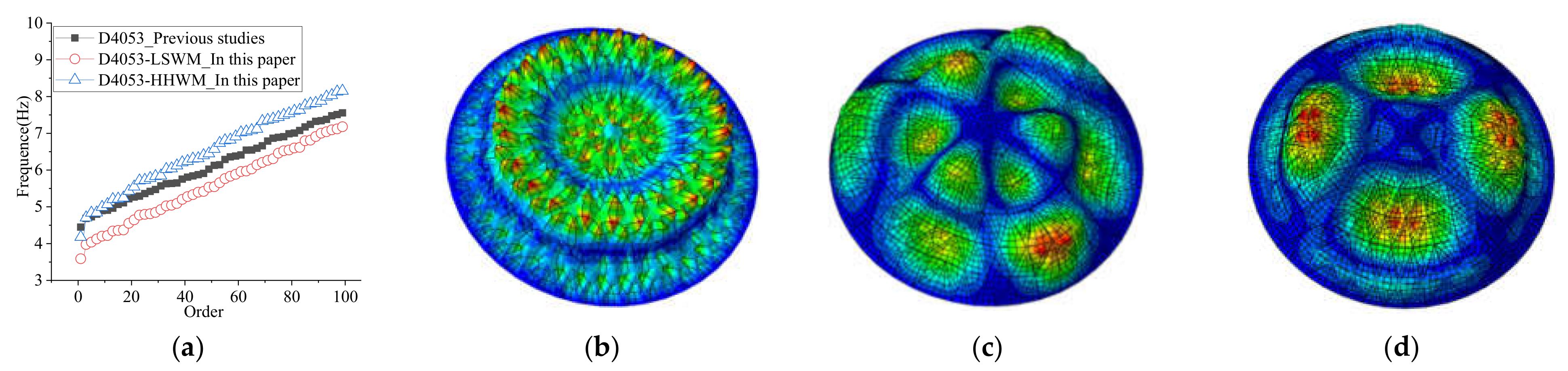
13]. In previous studies, the roofing system was directly connected with shell members without considering the influence of the purlin system and the connection between roof panel and shell members. The first 100 frequencies and the 8th order modes are compared in the shell of D4053.
As shown in
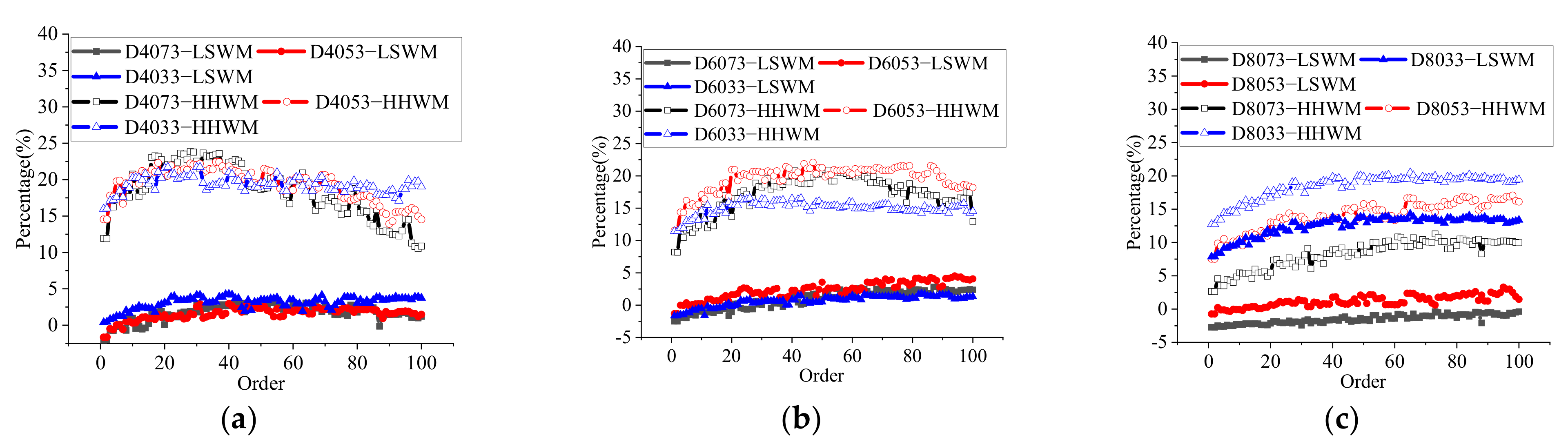
Figure 3a, there are larger differences between the finite element analysis results in previous studies and this paper. The fundamental frequency of the reticulated shell structure with the roofing system obtained by the previous research method is 19% and 7% higher than that of the bolted purlin roofing system and welded purlin roofing system established by the method in this paper. This difference occurs because the effects of the connection strength and stiffness between roof panel and shell members are not considered in previous studies, which significantly overestimates the skin effect of the roof panel on the reticulated shell structure. As shown in
Figure 3b–d, different modelling methods change the high-order modes of a reticulated shell structure, and different types of purlin joints will also make the high-order modes of reticulated shell structure different, which shows that it is necessary to consider the difference of purlin joints for the seismic response analysis of a reticulated shell structure. Based on this analysis, different finite element analysis methods for reticulated shell structures with roofing systems will lead to great differences in the dynamic response analysis. The finite element analysis method in this paper can reflect the influence of the main components of the roofing system in the reticulated shell structure and provide a better finite element analysis method for the seismic response analysis and strong earthquake failure analysis of reticulated shell structures with roofing systems.
3. Analysis of the Natural Frequency of the Shell with a Roofing System
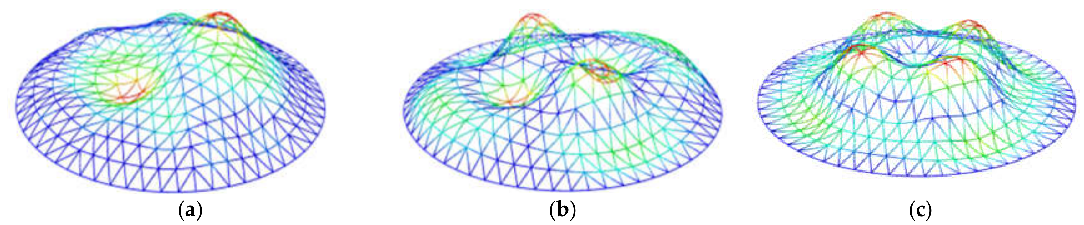
The influences of the roofing system are analysed by comparing the mode changes of the shell after the roofing system is added. The first buckling mode of the reticulated shell and roofing system is taken as the initial geometric imperfection mode of the structure, and the imperfection amplitude is taken as L/1500 (L—span of the shell).
As shown in
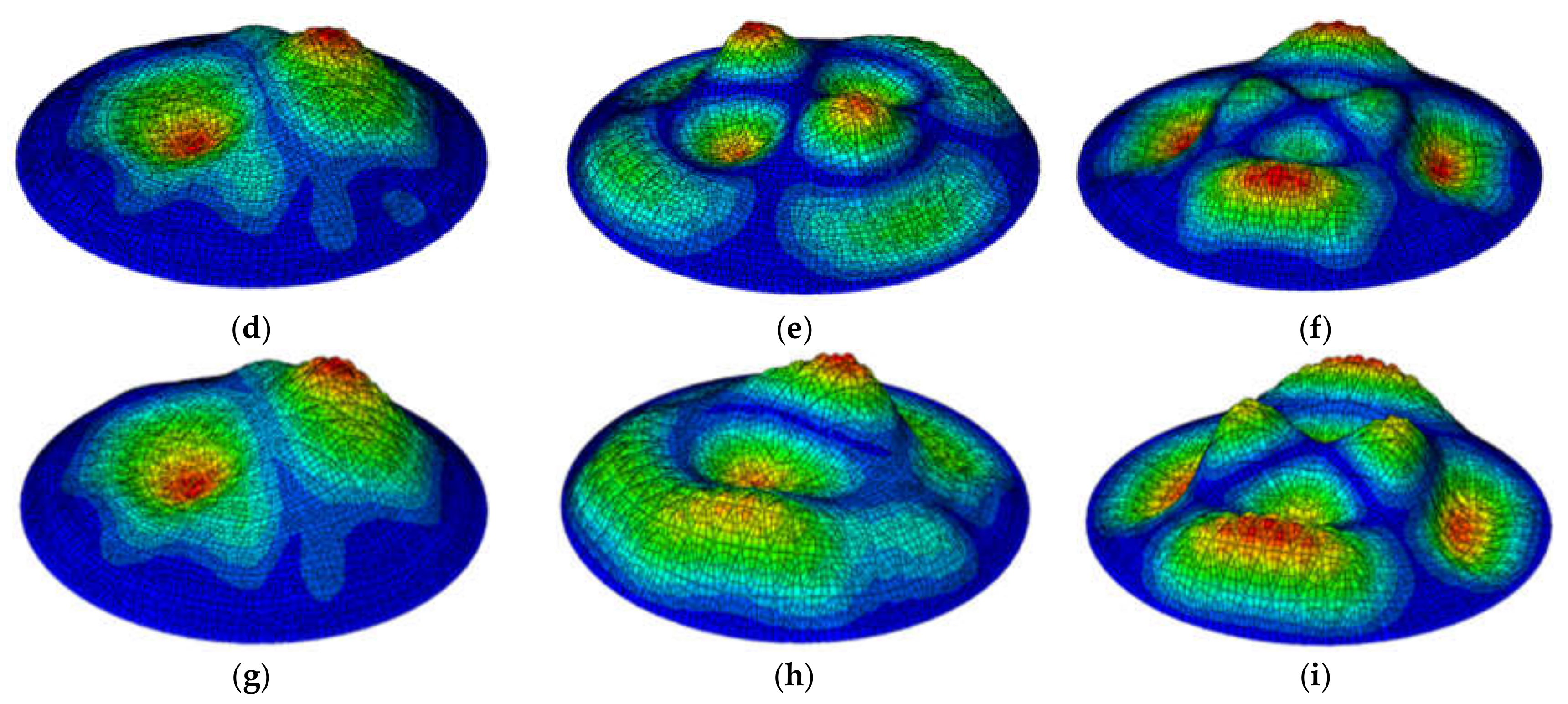
Figure 4, after the bolted purlin roofing system is installed, the first four lowest-order frequencies of the reticulated shell structure are reduced by approximately 1.4–3.0%, and the first six modes of the shell do not change notably. The reason is that the bolted purlin joints are relatively weak and cannot provide sufficient constraints on the shell nodes. Thus, this roofing system does not greatly increase the stiffness of the shell, although it increases the quality of the entire structure, which decreases the fundamental frequency of the shell. In contrast, the welded purlin roofing system increases the first 8th order frequencies of the shell by approximately 8.3–12.2%, and the vibration mode of the shell structure greatly changes from the 3rd order mode.
Figure 5 shows that the two types of roofing systems affect the first 100 frequencies of reticulated shell structures with different spans and rise-to-span ratios. The amplitude of the influence of the welded purlin roofing system on the fundamental frequency of the shell increases with increasing rise-to-span ratio and decreases with increasing span. The bolted purlin roofing system reduces the fundamental frequency of the shells with rise span ratios of 1/5 and 1/7, and the reduction amplitudes are approximately 0.7–1.65% and 2–2.7%, respectively.
4. Analysis of the Seismic Performance on the Shell with a Roofing System
4.1. Dynamic Time History Analysis
In this section, the seismic response of two shells (D4053 and D8073) is studied by dynamic time history analysis in the full load domain.
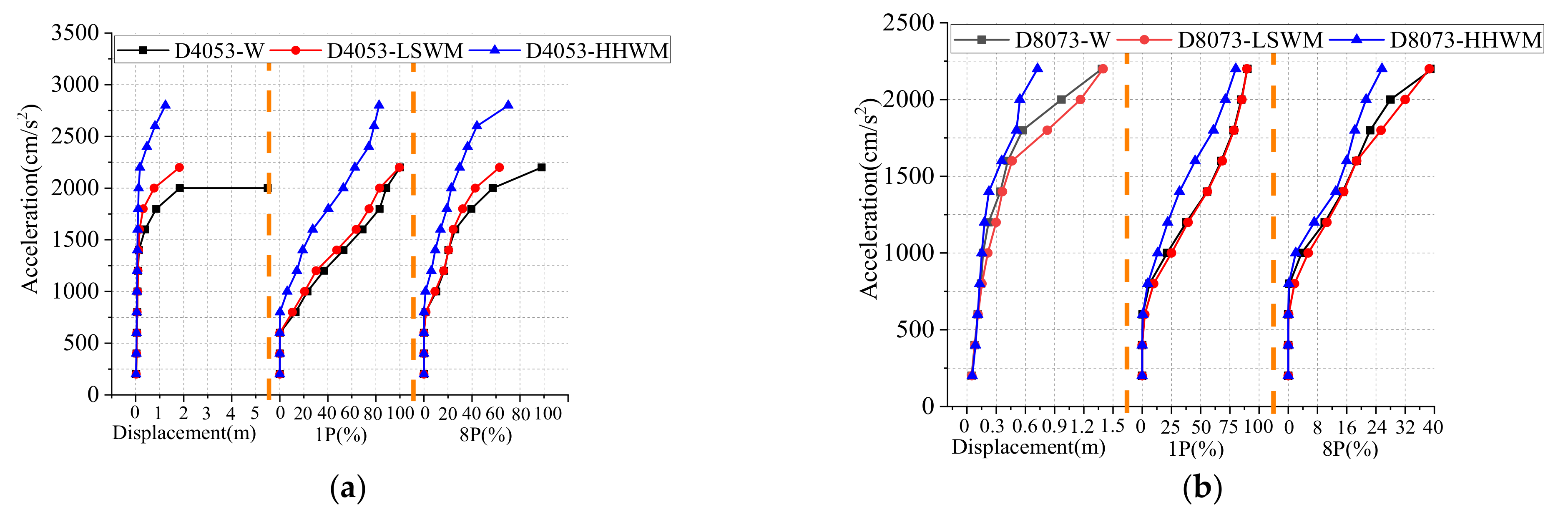
According to the above analysis, both roofing systems notably affect the seismic response of shell D4053, as shown in
Figure 6a. The bolted and welded purlin roofing systems greatly increase the ultimate seismic failure load of shell D4053 by 10 and 40%, respectively. Both roofing systems reduce the proportions of 1P and 8P plastic member percentages in the shell. As shown in
Figure 6b, the welded purlin roofing system reduces the maximum node displacement of shell D8073 by approximately to −13 to 7% and reduces the proportion of plastic members by approximately 1–24%. The bolted purlin roofing system greatly aggravates the deformation of shell D8073. In the entire loading process, the maximum node displacement of the shell increases by 6–45%.
As shown in
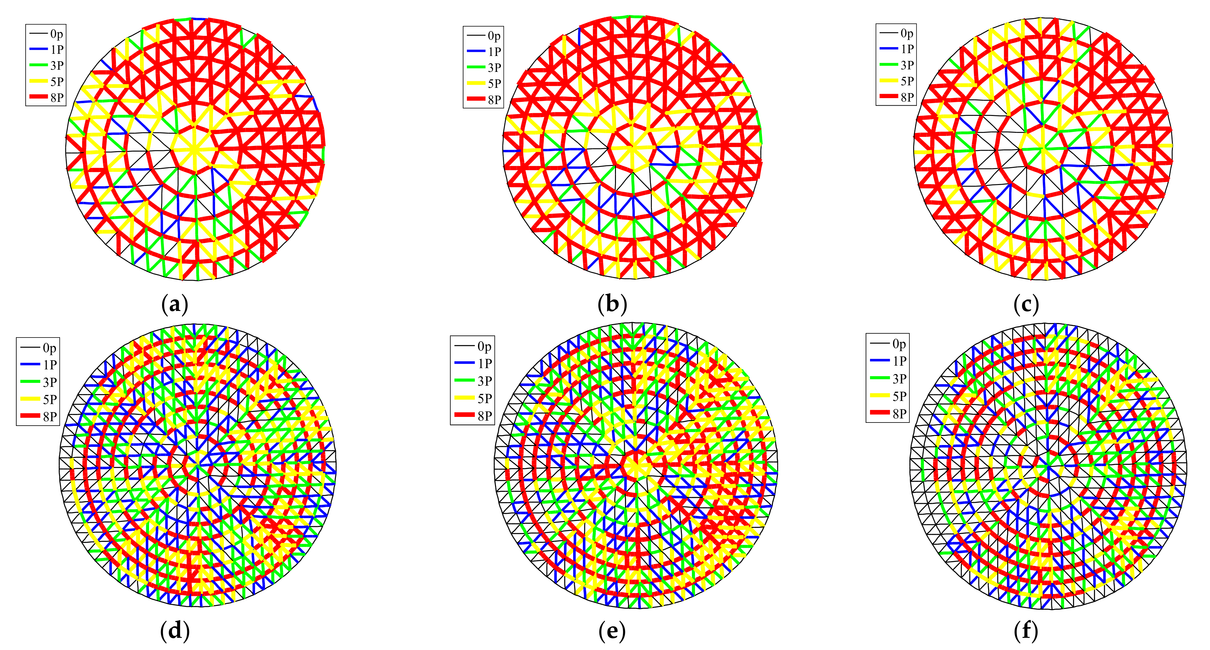
Figure 7a–c, the proportion of the full section yield (8P) shell members at the outermost edge of shell D0453 notably increases, which indicates that the roofing systems can assist the shell in transferring the load to the member near the support and improve the seismic performance of the structure. As shown in
Figure 7d–f, under a seismic acceleration amplitude of 1800 cm/s
2, shell D8073-LSWM exhibits more concentrated full-section yield members from near the third ring to the fourth ring from the support, which results in the continuous development of a local depression of the shell until failure occurs. According to this analysis, the roofing system can improve the degree of plastic development of the shell under seismic failure at the ultimate load, and the failure mode of the shell is more obvious than that of the dynamic strength.
4.2. Mechanism of the Influence of a Roofing System
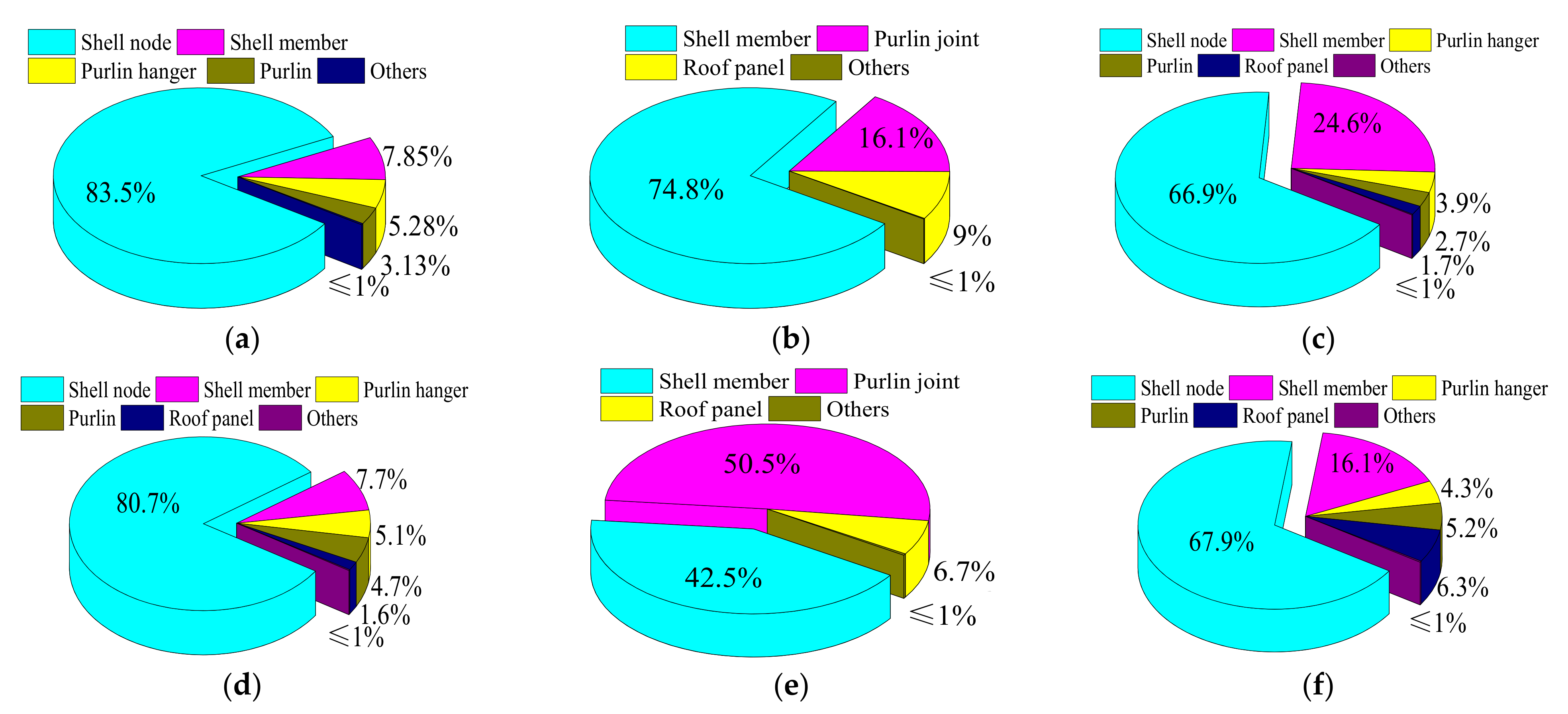
Figure 8 shows that in shell D4053 with a roofing system, most of the masses are concentrated on reticulated shell nodes and members, whose kinetic energy accounts for approximately 80% of the total kinetic energy of the structure under earthquake loading. Under the ultimate seismic failure load, the deformation energy consumption of the purlin joints in the two roofing systems accounts for 16.1 and 50.5% of the total deformation energy of the structure, the deformation energy consumption of the roof panels accounts for 8.95 and 6.68% of the total deformation energy of the structure, and the deformation energy consumption of other parts in the roofing system accounts for less than 1%. The damping energy consumption of the two types of roofing systems accounts for approximately 9.3 and 16% of the total damping energy consumption, of which the roof panel accounts for approximately 2.7 and 6.3%. Based on this analysis, for the shell with two roofing systems, the purlin joint is the main component for deformation energy dissipation, and it is necessary to further study the influence of purlin joints on the seismic performance of the shell with the roofing systems.
In the dynamic time history analysis of the shell with a roofing system, all components of the roofing system and the shell jointly bear the seismic action and consume seismic energy.
After installing the roofing system, the purlin and roof panel increase the axial stress area and flexural section modulus of the shell member and the membrane stiffness and flexural stiffness of the shell. The roofing system can make the shell members bear a larger axial force and out-of-surface bending moment, which improves the seismic performance of the shell. The purlin joint is an important force transfer component in the roofing system; it is generally connected to the purlin hanger with bolts or welds, and their mechanical properties are weaker than those of the purlin members. In the dynamic time history analysis, with the increase in axial force and bending moment in the purlin members, the axial stiffness and flexural stiffness of the purlin joint enter the nonlinear stage; when the purlin joint undergoes plastic deformation, the purlin member remains in the elastic stage. Therefore, damage to the purlin joint is the key to the ability of the roofing system to affect the seismic performance of the single-layer spherical reticulated shell structure.
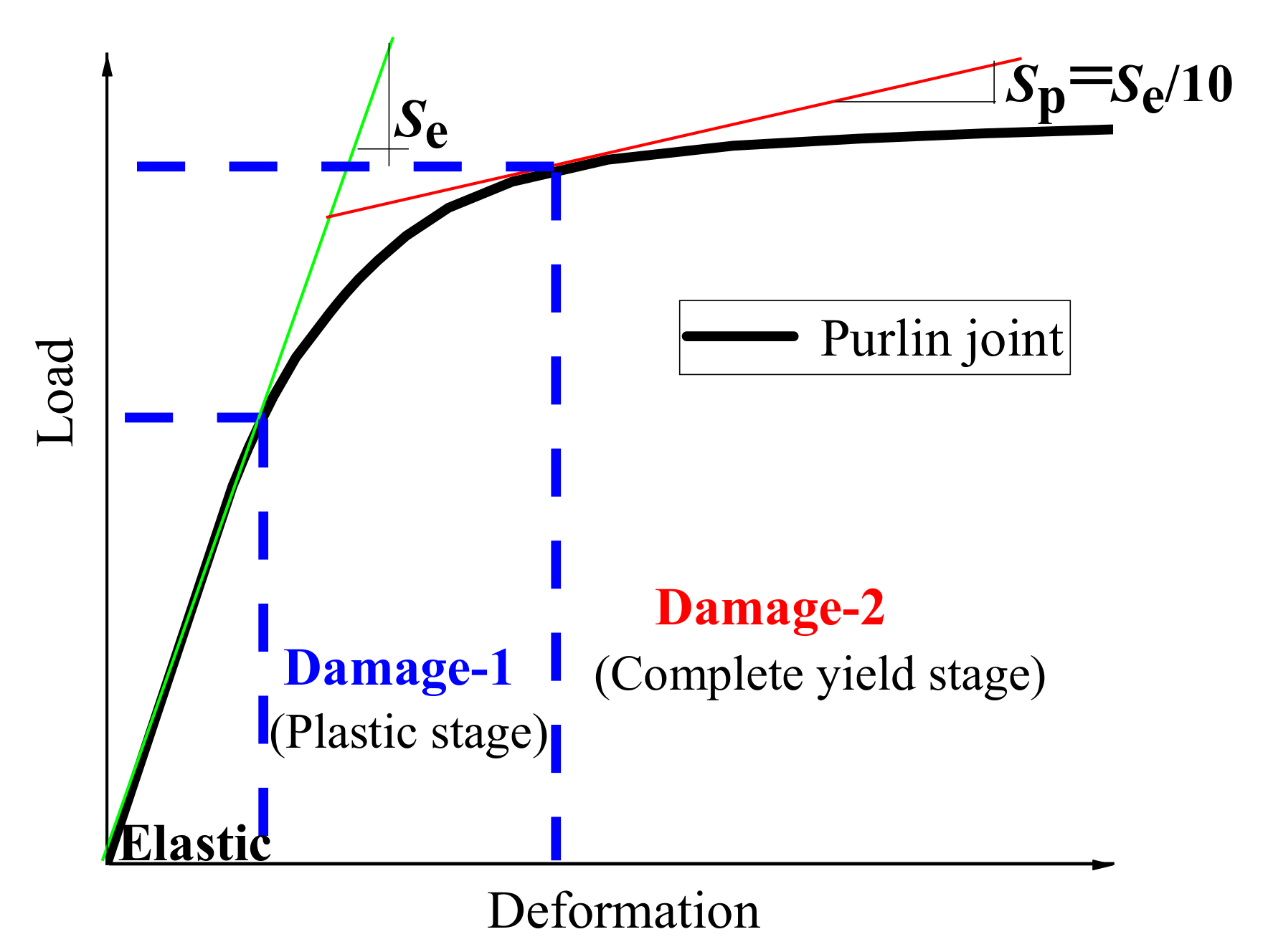
When the purlin joint bears increasing axial load or bending moment, the load-deformation curves of the purlin joint generally show three stages according to the joint damage degree in the single-layer spherical reticulated shell with semi-rigid joints [
16]: an elastic stage, a plastic stage and a complete yield stage. As shown in
Figure 9, the stage before the plastic deformation of the purlin joint in the axial load-displacement curve or moment-rotation curve is defined as the elastic stage. When the axial load or bending moment increases, the axial stiffness or flexural stiffness of the purlin joint begins to enter the nonlinear stage. The stage from the beginning of plastic deformation in the purlin joint to the reduction in stiffness to 10% of the initial stiffness (
Se) is defined as the Damage-1 stage. With the continuous increase in load, the plastic deformation of the purlin joint gradually deepens, and the stage in which the axial stiffness or flexural stiffness of the purlin joint decreases to less than 10% of the initial stiffness is defined as the Damage-2 stage. Thus, the purlin joint has been seriously damaged and cannot provide effective constraints for the shell with the roofing system.
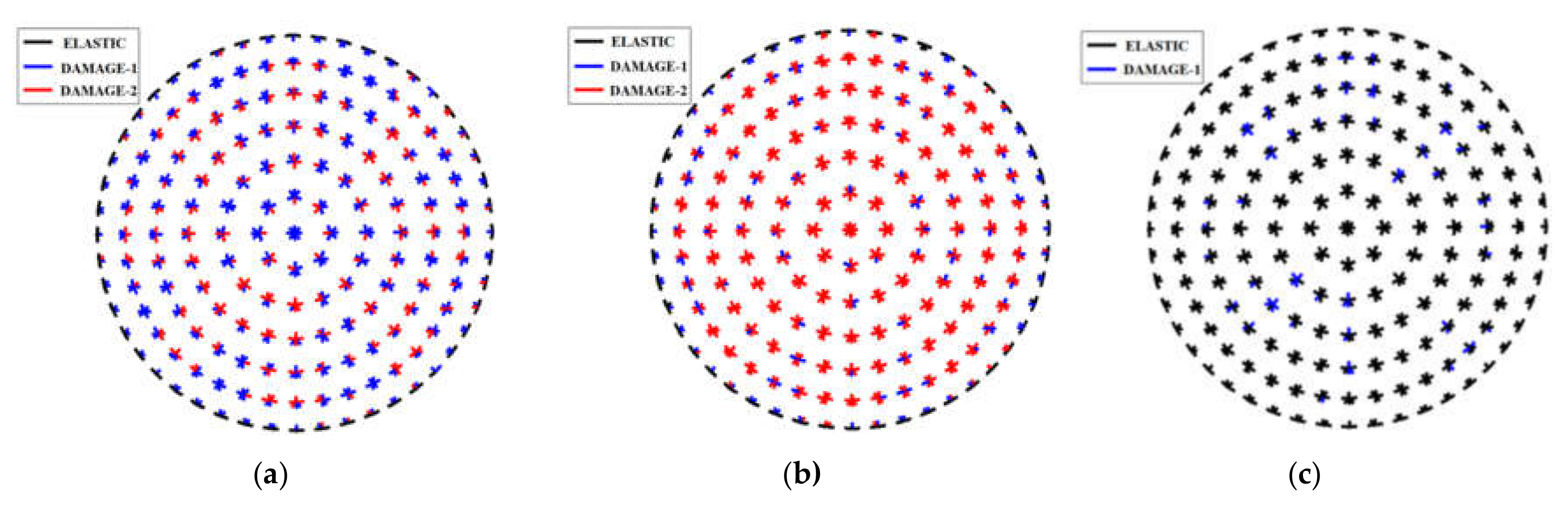
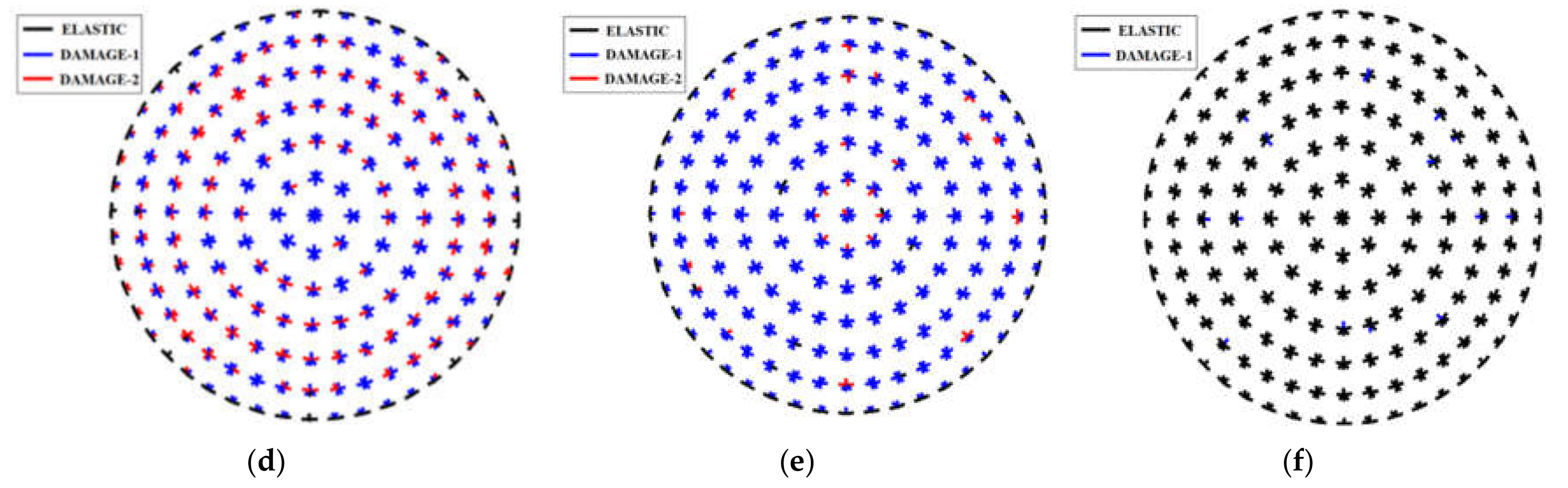
Figure 10a–f shows that in the bolted and welded purlin roofing systems, 89.7 and 87.7% of the axial constraints of purlin joints enter the Damage-1 stage, respectively, of which 33.1 and 27.4% enter the Damage-2 stage. Additionally, 88.8 and 88.3% of the out-of-surface bending constraints enter the Damage-1 stage, of which 73.1 and 9% enter the Damage-2 stage, and 8.3 and 1.75% of the in-surface bending constraints enter the Damage-1 stage. Based on this analysis, the out-of-surface bending constraints and axial constraints of the purlin joints are the main factors of the roofing system that affect the seismic performance of the reticulated shell structure. Bolted purlin joints are more prone to serious out-of-surface bending constraint failure, while welded purlin joints are more prone to serious axial constraint failure.
5. Discussion on the Influence on the Seismic Performance of the Shell with Different Parameters
According to the seismic response analysis of the reticulated shell with the roofing systems, the roofing system obviously affects the seismic response of the spherical reticulated shell, plastic development of the reticulated shell members, and local failure of the shell. The percent change in maximum node displacement of the reticulated shell before and after the addition of a roofing system is defined as the seismic influence coefficient of the roofing system (γ), as shown in Equation (1), where Dshell,max is the maximum node displacement of the reticulated shell without a roofing system, and Dshell,roof is the maximum node displacement of the reticulated shell with a roofing system. The proportion of the plastic shell members that change after the addition of a roofing system is defined as the variation coefficient of the plastic members of the shell (α), as shown in Equation (2), where Sshell,1P is the percentage of plastic shell members in the shell without a roofing system, and Sroof,1P is the percentage of plastic shell members in the shell with the roofing system.
In this section, a seismic performance analysis is conducted on reticulated shells with roofing systems of different spans, rise-to-span ratios, ground motions and purlin joint coefficients. The analysis parameters are shown in
Table 1. The seismic accelerations in three directions are applied to the reticulated shell structure. The proportion of three-direction peak ground accelerations (PGAs) is not changed, and the maximum PGA amplitude is adjusted until the ultimate failure load of the reticulated shell structures is reached.
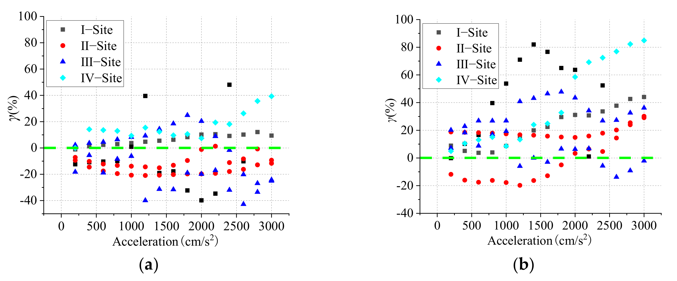
5.1. Influence of Different Ground Motions
Seven ground motions at different sites are applied to the shell with a roofing system, as shown in
Table 2 according to the code for seismic design of buildings in China. The average frequencies of seven ground motions are 1.1–3.2 Hz [
17,
18], which can envelope most of the basic frequencies of most reticulated shell structures. The effects of the roofing system on the maximum node displacement of the spherical reticulated shell under the ground motions of different sites are analysed.
As shown in
Figure 11, the influence ranges of the bolted and welded purlin roofing systems on the maximum node displacement of the shell are approximately to −43 to 49% and to −20 to 83%, respectively.
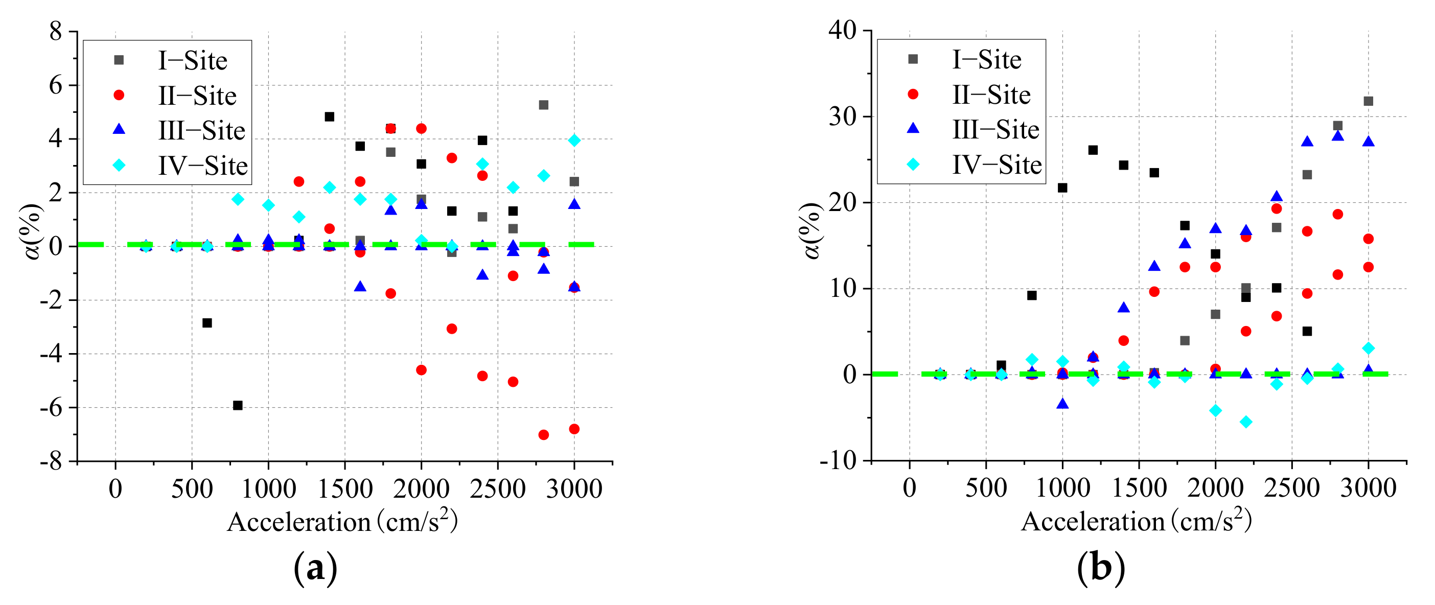
Figure 12 shows that the proportions of plastic members of the shell more obviously decrease. Under the action of ground motions of Class-II and -III sites, the bolted purlin roofing system notably deepens the plastic deformation of the shell members. Based on these analysis results, the bolted purlin roofing system more strongly aggravates the seismic response of the shell under the seismic action of Class-II and -III sites.
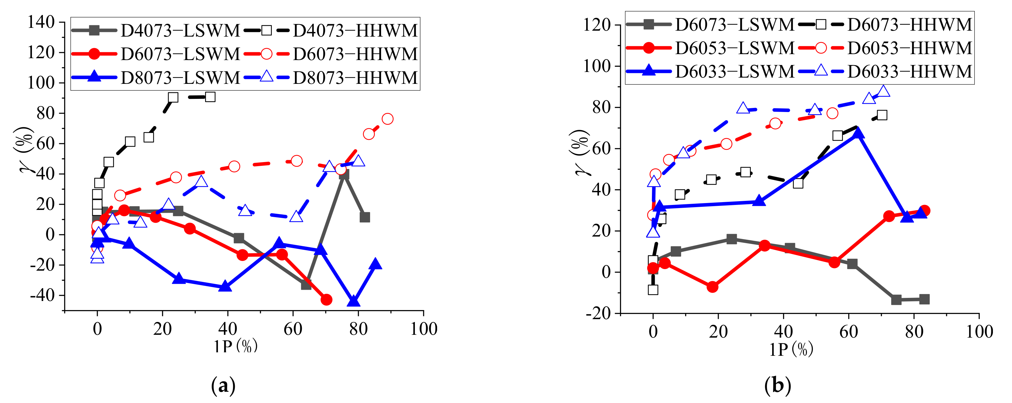
5.2. Influence of the Span and Rise-To-Span Ratio
The seismic responses of single-layer spherical reticulated shells with spans of 40, 60 and 80 m and rise-to-span ratios of 1/7, 1/5 and 1/3 under the influence of two roofing systems are analysed. The Taft seismic wave (Kern County, 1952) is selected for loading.
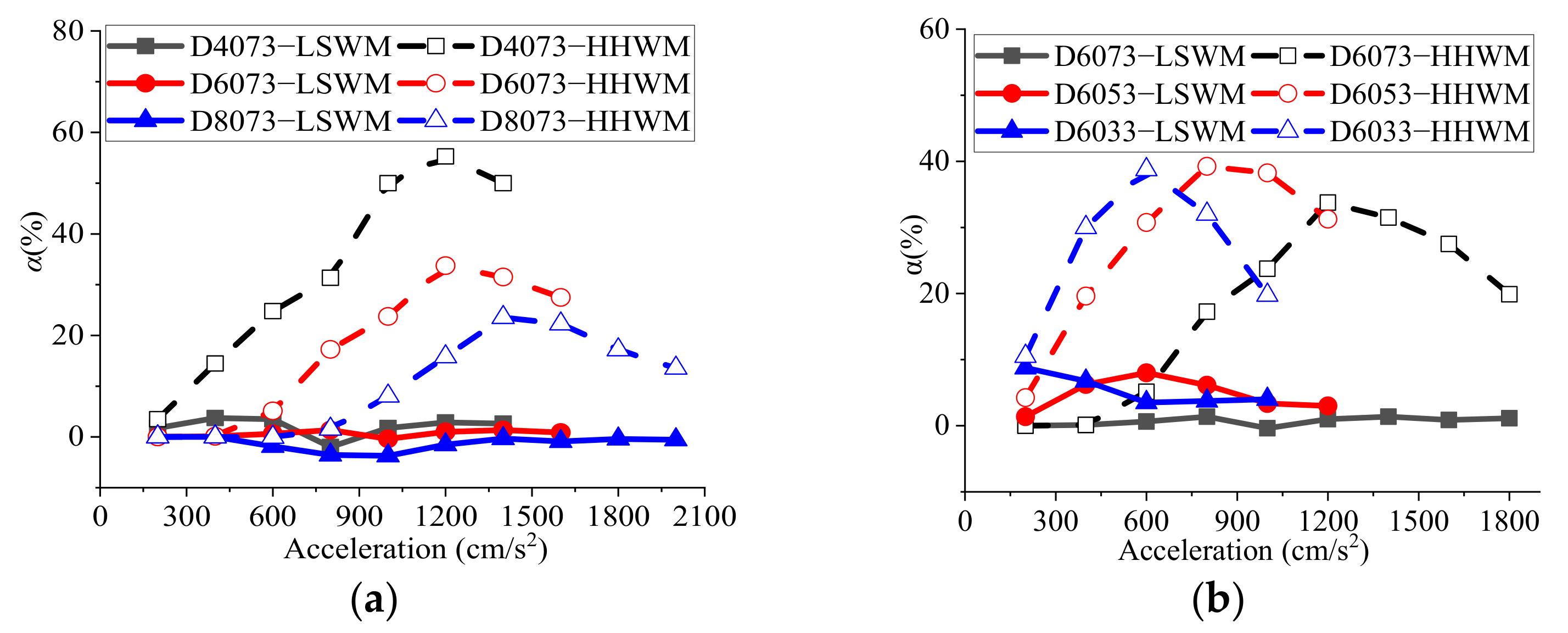
Figure 13 shows that with the increase in proportion of plastic members in the shells, the seismic reduction effect of the welded purlin roofing system on the shell gradually increases, and that of the bolted purlin roofing system first increases and subsequently decreases. The trend is most obvious in the shell with a 1/7 rise-to-span ratio, which is mainly due to the much smaller degree of damage of the welded purlin joints than the bolted purlin joints. Generally, the seismic reduction effect of the two roofing systems decreases with increasing span of the shell and increases with increasing rise-to-span ratio. As shown in
Figure 14, the effects of the two roofing systems on reducing the proportion of plastic members of the shell increase and are more obvious with the decrease in span of the shells. When the seismic acceleration amplitude is less than 600 cm/s
2, the two roofing systems more strongly reduce the proportion of plastic members of the shells with rise-to-span ratios of 1/5 and 1/3 vs. 1/7.
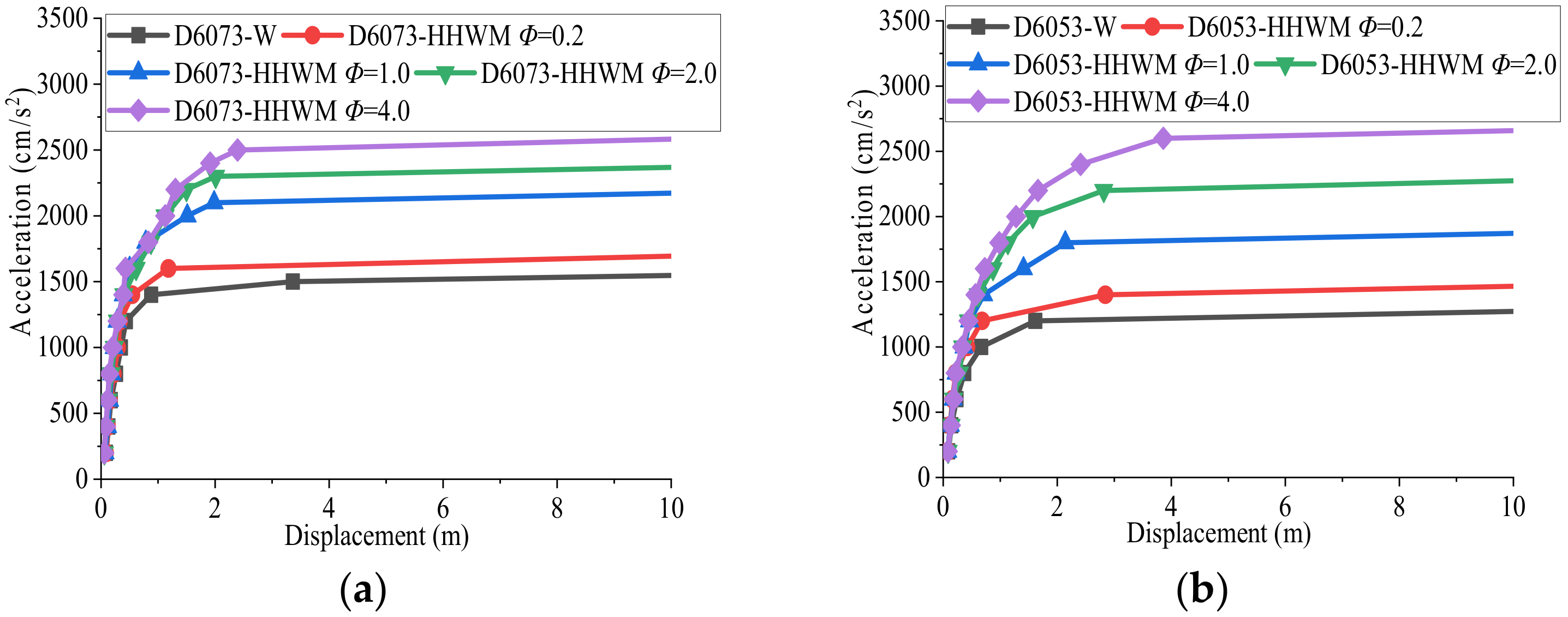
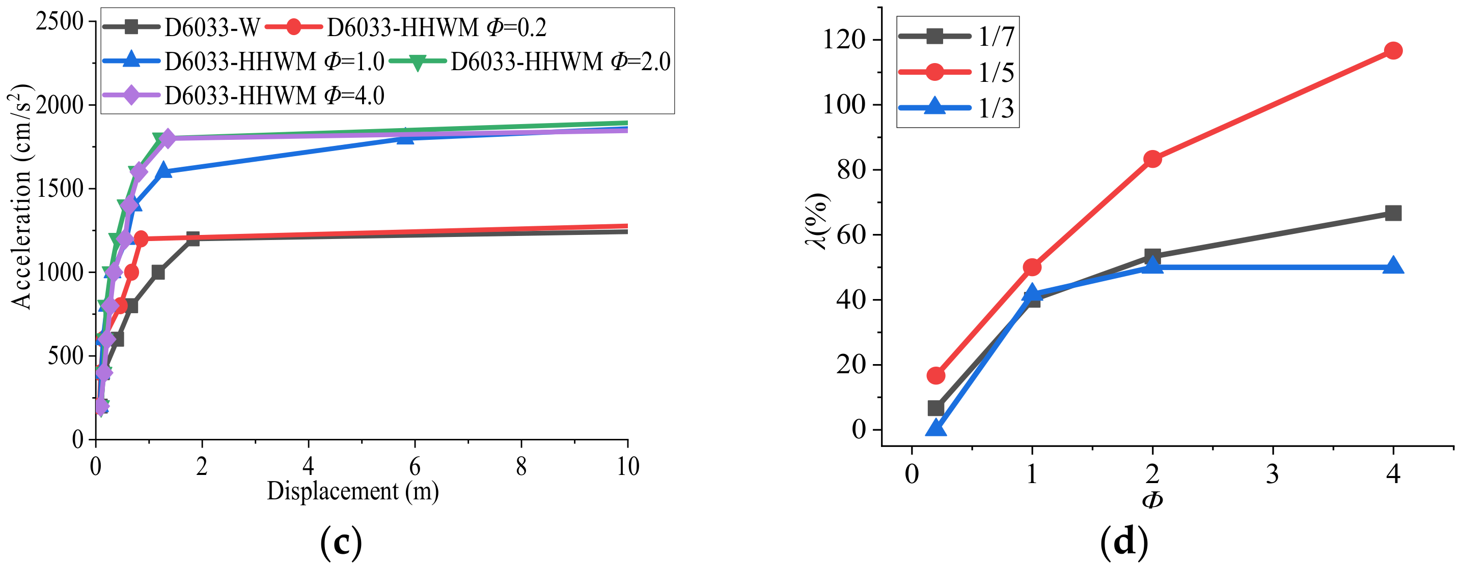
5.3. Influence of the Purlin Joint Coefficients
The strength and stiffness of the purlin joints are the key factors that affect the seismic performance of the shell with a roofing system. In this section, the purlin joint coefficient (
Φ) is defined as the multiple of purlin joint strength and stiffness. The influence of
Φ in the roofing system on the seismic performance of the shell is defined as the seismic ultimate failure load coefficient (
λ), as shown in Equation (3), where
LR is the seismic ultimate failure load of the shell with the roofing system, and
LS is the seismic ultimate failure load of the shell without the roofing system.
Based on the analysis, there are obvious differences in the effects of different purlin joint coefficients on the seismic performance of the shell.
Figure 15 shows that with the increase in purlin joint coefficient, the seismic ultimate failure load of the shell with a roofing system increases, and the purlin joint coefficient has the greatest effect on the improvement of the shell with a 1/5 rise-to-span ratio.
Figure 15c shows that when the purlin joint coefficient is 0.2, the roofing system does not increase the ultimate failure load of the shell but notably reduces the maximum displacement of the shell node, and the proportion of shell members with the full section yield is reduced by 8%. When the welded purlin roofing system is adopted for the shell with a 1/3 rise-to-span ratio, if the strength and stiffness of the purlin joint are weak, then the roofing system increases the risk of sudden collapse of the shell.
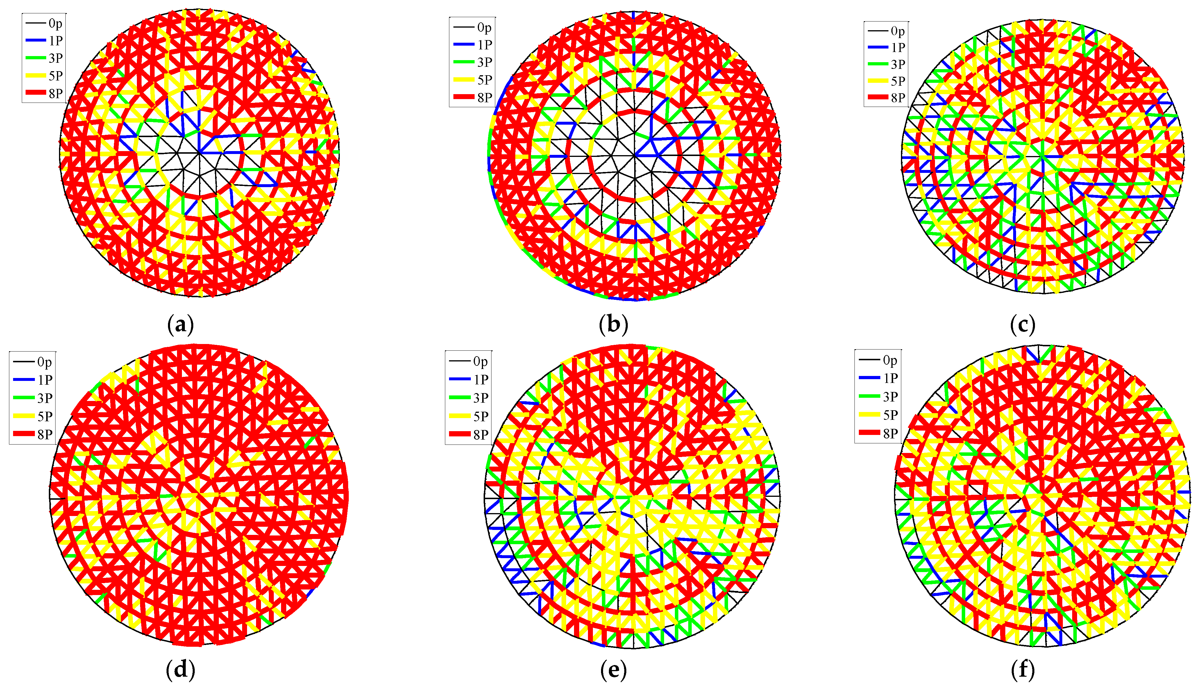
The roofing system with different purlin joint coefficients also considerably influences the seismic damage of the shell.
Figure 16a,b shows two obvious depressions near the fourth ring nodes near the central node and the second ring nodes near the support in D6033-W under the ultimate load. The shell eventually developed damage along these two depressions and finally collapsed. In D6033-HHWM (
Φ = 4.0), the failure phenomenon is that of full section yield in many members around the second ring nodes near the support, and the plastic development in some members near the central node of the shell is lower.
Figure 16c,d shows that when the rise-to-span ratio is 1/5 and the purlin joint coefficient is 4.0, the roofing system intensifies the development of the full section yield members of the shell under the seismic ultimate failure load, and 81.4% of the members’ yield in the full section of the shell. However, the proportion of full section yield in the shell without a roofing system is only 37.6%, which indicates that the roofing system with a larger purlin joint coefficient can more fully promote plastic development of the shell with a 1/5 rise-to-span ratio, and the dynamic strength failure of the shell is more obvious.
Figure 16e,f shows that when the rise-to-span ratio of the shell is 1/7, the change in purlin joint coefficient hardly affects the development of plastic shell members under the seismic ultimate failure load of the shell, and the failure of the shell has not notably changed.
6. Conclusions
In this paper, the seismic performance of a single-layer spherical reticulated shell with a roofing system was determined. The roofing system notably affected the maximum node displacement of the shell and even changed the seismic failure behaviour of the shell. The following conclusions were obtained:
- (1)
The roofing system notably affected the natural vibration characteristics of a single-layer spherical reticulated shell. Bolted and welded purlin roofing systems changed the high-order vibration modes of the shell. The bolted purlin roofing system reduced the fundamental frequency of the shell by approximately 0.7–2.7%, and the welded purlin roofing system increased the fundamental frequency of the shell by approximately 8.3–12.2%. The influence of the welded purlin roofing system on the fundamental frequency of the shell increased with increasing rise-to-span ratio and decreased with increasing span.
- (2)
Under the action of an earthquake, many bolted purlin joints yield, which makes the bolted purlin roofing system fail to provide sufficient constraints for reticulated shell structures. At this time, the bolted purlin roofing system is equivalent to the external load applied to the reticulated shell structure, which will aggravate the deformation of the reticulated shell structure. The welded purlin joints have larger strength and stiffness, most welded purlin joints will not seriously yield, and the welded purlin roofing system can more effectively restrict the reticulated shell nodes and reduce the displacement response of the shell.
- (3)
The purlin joints can provide the out-of-surface bending constraint, which can effectively restrain the obvious out-of-surface deformation of reticulated shell nodes. The axial constraint of purlin joints can ensure the load transfer of reticulated shell nodes on purlins. The out-of-surface bending constraint and axial constraint of the purlin joints in the roofing system are the main factors that affect the seismic response of single-layer spherical reticulated shells. The roofing system and shell together consume seismic energy, the purlin joint is the main deformation energy dissipation component of the roofing system, the energy dissipation effect of welded purlin joints is more obvious, and the roof panels consume nearly 10% of the total deformation energy, which cannot be ignored. With the increase in proportion of plastic shell members, the seismic reduction effect of the welded purlin roofing system on the spherical reticulated shell gradually increases, and the seismic reduction effect of the bolted purlin roofing system first increases and subsequently decreases. This behaviour is most obvious in the shell with a 1/7 rise-to-span ratio.
- (4)
Under the ground motions of Class-II and -III sites, the seismic influence coefficient of the bolted purlin roofing system on the single-layer spherical reticulated shell fluctuated between −43 and approximately 24%, and the bolted purlin roofing system more greatly aggravated the displacement response of the shell than the welded purlin roofing system. When the proportion of plastic members of the reticulated shell was small and the rise-to-span ratio of the shell was larger, the seismic reduction effects of the bolted purlin and welded purlin roofing systems were more obvious, and these effects decreased with increasing span of the shell. A greater purlin joint coefficient corresponds to a more obvious seismic reduction effect of the roofing system on the shell and even (notably) the change in damage behaviour of the shell. The shell with a 1/5 rise-to-span ratio was more sensitive than shells with other rise-to-span ratios to the change in purlin joint coefficient.
Author Contributions
Conceptualization, W.L.; methodology, W.L.; software, W.L.; validation, W.L.; formal analysis, W.L.; investigation, W.L.; resources, W.L.; data curation, W.L.; writing—original draft preparation, W.L. and X.Z.; writing—review and editing, W.L. and X.Z.; visualization, W.L.; supervision, X.Z. and F.F.; project administration, X.Z. and F.F.; funding acquisition, X.Z. and F.F. All authors have read and agreed to the published version of the manuscript.
Funding
This study was supported by the National Key Research and Development Program of China (2018YFC1504304), the Creative Research Groups of the National Natural Science Foundation of China (51921006) and the Natural Science Foundation of Heilongjiang Province of China (JQ2020E004).
Institutional Review Board Statement
Not applicable.
Informed Consent Statement
Not applicable.
Data Availability Statement
The data presented in this study are available on request from the corresponding author.
Acknowledgments
The authors extend their sincere gratitude for the support of Space Structure Research Center in School of Civil Engineering in Harbin Institute of Technology (Harbin).
Conflicts of Interest
The authors declare no conflict of interest.
References
- Cao, Z.; Zhang, Y. Analysis of Seismic Response Characteristics of Single Layer Spherical Reticulated Shells. Build. Struct. 1998, 8, 195–201. [Google Scholar]
- Lin, J.; Zhang, Y.; Zhao, Y. Seismic Analysis Methods of Long-Span Structures and Recent Advances. Adv. Mech. 2001, 31, 350–360. [Google Scholar]
- Fan, F.; Wang, M.L.; Cao, Z.G.; Shen, S. Seismic Behaviour and Seismic Design of Single-Layer Reticulated Shells with Semi-Rigid Joint System. Adv. Struct. Eng. 2012, 15, 1829–1841. [Google Scholar] [CrossRef]
- Ma, H.H.; Shan, Z.W.; Fan, F. Dynamic Behaviour and Seismic Design Method of Single-layer Reticulated Shell with Semi-Rigid Joints. Thin-Walled Struct. 2017, 119, 544–557. [Google Scholar] [CrossRef]
- Fan, F.; Zhi, X.D.; Shen, S. Failure Mechanism of Reticulated Shells under Earthquake, 2nd ed.; Science Press: Beijing, China, 2013; pp. 19–44. [Google Scholar]
- Zhi, X.D.; Fan, F.; Shen, S. Responses and Failure Mechanism of the Single-Layer Reticular Domes Subjected to Earthquake Motion. World Earthq. Eng. 2007, 23, 88–94. [Google Scholar]
- Zhi, X.D.; Fan, F.; Shen, S. Seismic Failure of Single-Layer Reticulated Domes. Eng. Mech. 2008, 25, 7–12. [Google Scholar]
- Chen, Y.; Shen, Z.; Xi, C. Study on Seismic Performance of Space Truss Considering Interaction of Roof and Slab. In Proceedings of the Sixth Conference on Spatial Structure, Guangzhuo, China, 2 December 1992; pp. 236–241. [Google Scholar]
- Koliou, M. Seismic Analysis and Design of Rigid Wall-Flexible Roof Diaphragm Buildings; State University of New York: New York, NY, USA, 2014. [Google Scholar]
- Koliou, M.; Filiatrault, A.; Kelly, D.J.; Lawson, J. Buildings with Rigid Walls and Flexible Roof Diaphragms. I: Evaluation of Current U.S. Seismic Provisions. J. Struct. Eng. 2016, 142, 04015166-1-13. [Google Scholar] [CrossRef]
- Koliou, M.; Filiatrault, A.; Kelly, D.J.; Lawson, J. Buildings with Rigid Walls and Flexible Roof Diaphragms. II: Evaluation of a New Seismic Design Approach Based on Distributed Diaphragm Yielding. J. Struct. Eng. 2016, 142, 04015167-1-9. [Google Scholar] [CrossRef]
- Cao, Z.; Zhou, C.; Yan, J. Seismic Response Analysis of an 80-meter Span Single-Layer Reticulated Dome with Bolt-Ball Joints. J. Harbin Inst. Technol. 2017, 49, 58–65. [Google Scholar]
- Zhou, Y. Shaking Table Tests and Performance Study of Single-Layer Reticulated Cylindrical Shells with Skin Diaphragm; Beijing University of Technology: Beijing, China, 2012. [Google Scholar]
- Li, W.; Zhi, X.; Wang, D.; Fan, F.; Shen, S. Static Stability Analysis of a Reticulated Shell with a Roofing System. Eng. Struct. 2019, 185, 315–331. [Google Scholar] [CrossRef]
- Li, W.; Zhi, X.; Wang, D.; Fan, F.; Shen, S. Influence of a Roofing System on the Static Stability of Reticulated Shells. Adv. Steel Constr. 2020, 16, 363–369. [Google Scholar]
- Ma, H.H. Study on Mechanical Behavior and Design Theory of Single-Layer Spherical Reticulated Shell with Semi-Rigid Joints; Harbin Institute of Technology: Harbin, China, 2011. [Google Scholar]
- Ministry of Housing and Urban-Rural Development of the People’s Republic of China. Code for Seismic Design of Building; China Planning Press: Beijing, China, 2016.
- Song, R.; Li, Y.; van de Lindt, J.W. Impact of Earthquake Ground Motion Characteristics on Collapse Risk of Post-Main. Eng. Struct. 2014, 81, 349–361. [Google Scholar] [CrossRef]
Figure 1.
Experimental models of a simple reticulated shell structure with a roofing system: (a) the shell without roofing system; (b) the shell with roofing system; (c) comparison of experimental and simulation results.
Figure 1.
Experimental models of a simple reticulated shell structure with a roofing system: (a) the shell without roofing system; (b) the shell with roofing system; (c) comparison of experimental and simulation results.
Figure 2.
The FEM of spherical reticulated shells with a roofing system adapted from Ref. [
16]: (
a) equivalent panel; (
b) weakened area; (
c) purlin; (
d) purlin hanger; (
e) pillar; (
f) single-layer spherical reticulated shell; (
g) reticulated shell structures with roofing system.
Figure 2.
The FEM of spherical reticulated shells with a roofing system adapted from Ref. [
16]: (
a) equivalent panel; (
b) weakened area; (
c) purlin; (
d) purlin hanger; (
e) pillar; (
f) single-layer spherical reticulated shell; (
g) reticulated shell structures with roofing system.
Figure 3.
Comparisons of the finite element analysis methods in the previous studies and this paper: (a) the first 100 frequencies; (b) the 8th order mode for D4053 in previous studies; (c) the 8th order mode for D4053-LSWM in this paper; (d) the 8th order mode for D4053-HHWM in this paper.
Figure 3.
Comparisons of the finite element analysis methods in the previous studies and this paper: (a) the first 100 frequencies; (b) the 8th order mode for D4053 in previous studies; (c) the 8th order mode for D4053-LSWM in this paper; (d) the 8th order mode for D4053-HHWM in this paper.
Figure 4.
Modal comparison of the shell with various roofing systems: (a) D4053-1500-W 1st order (2.52 Hz); (b) D4053-1500-W 3rd order (2.70 Hz); (c) D4053-1500-W 8th order (2.80 Hz); (d) D4053-1500-LSWM 1st order (2.46 Hz); (e) D4053-1500-LSWM 3rd order (2.66 Hz); (f) D4053-1500-LSWM 8th order (2.76 Hz); (g) D4053-1500-HHWM 1st order (2.73 Hz); (h) D4053-1500-HHWM 3rd order (3.02 Hz); (i) D4053-1500-HHWM 8th order (3.14 Hz).
Figure 5.
The comparison of the frequencies of the shell with various roofing systems: (a) 40 m; (b) 60 m; (c) 80 m.
Figure 5.
The comparison of the frequencies of the shell with various roofing systems: (a) 40 m; (b) 60 m; (c) 80 m.
Figure 6.
Maximum displacement and proportion of the plastic shell member curves: (a) D4053; (b) D8073.
Figure 6.
Maximum displacement and proportion of the plastic shell member curves: (a) D4053; (b) D8073.
Figure 7.
Distributions of the plastic shell member in the shell with various roofing systems: (a) D4053-W 2000 cm/s2; (b) D4053-LSWM 2200 cm/s2; (c) D4053-HHWM 2200 cm/s2; (d) D8073-W 1800 cm/s2; (e) D8073-LSWM 1800 cm/s2; (f) D8073-HHWM 1800 cm/s2.
Figure 7.
Distributions of the plastic shell member in the shell with various roofing systems: (a) D4053-W 2000 cm/s2; (b) D4053-LSWM 2200 cm/s2; (c) D4053-HHWM 2200 cm/s2; (d) D8073-W 1800 cm/s2; (e) D8073-LSWM 1800 cm/s2; (f) D8073-HHWM 1800 cm/s2.
Figure 8.
Energy dissipation distributions of the components in the shells: (a) D4053-LSWM 2200 cm/s2 kinetic energy; (b) D4053-LSWM 2200 cm/s2 deformation energy; (c) D4053-LSWM 2200 cm/s2 damping energy consumption; (d) D4053-HHWM 2800 cm/s2 kinetic energy; (e) D4053-HHWM 2800 cm/s2 deformation energy; (f) D4053-HHWM 2800 cm/s2 damping energy consumption.
Figure 9.
Damage stage divisions of a purlin joint.
Figure 9.
Damage stage divisions of a purlin joint.
Figure 10.
Damage distributions of purlin joints: (a) D4053-LSWM axial; (b) D4053-LSWM out-of-surface; (c) D4053-LSWM in-surface; (d) D4053-HHWM axial; (e) D4053-HHWM out-of-surface; (f) D4053-HHWM in-surface.
Figure 10.
Damage distributions of purlin joints: (a) D4053-LSWM axial; (b) D4053-LSWM out-of-surface; (c) D4053-LSWM in-surface; (d) D4053-HHWM axial; (e) D4053-HHWM out-of-surface; (f) D4053-HHWM in-surface.
Figure 11.
Values of γ and the seismic amplitude for the shell with each roofing system: (a) bolted purlin roofing system; (b) welded purlin roofing system.
Figure 11.
Values of γ and the seismic amplitude for the shell with each roofing system: (a) bolted purlin roofing system; (b) welded purlin roofing system.
Figure 12.
Values of α and the seismic amplitude for the shell with each roofing system: (a) bolted purlin roofing system; (b) welded purlin roofing system.
Figure 12.
Values of α and the seismic amplitude for the shell with each roofing system: (a) bolted purlin roofing system; (b) welded purlin roofing system.
Figure 13.
Values of γ−1P for shells with different spans and rise-to-span ratios: (a) influence of the span; (b) influence of the rise-to-span ratio.
Figure 13.
Values of γ−1P for shells with different spans and rise-to-span ratios: (a) influence of the span; (b) influence of the rise-to-span ratio.
Figure 14.
Values of α-1p for shells with different spans and rise-to-span ratios: (a) Influence of the span; (b) influence of the rise-to-span ratio.
Figure 14.
Values of α-1p for shells with different spans and rise-to-span ratios: (a) Influence of the span; (b) influence of the rise-to-span ratio.
Figure 15.
Seismic response curves of the shells with different purlin joint coefficients and the Φ-λ relationship: (a) D6073; (b) D6053; (c) D6033; (d) Φ-λ.
Figure 15.
Seismic response curves of the shells with different purlin joint coefficients and the Φ-λ relationship: (a) D6073; (b) D6053; (c) D6033; (d) Φ-λ.
Figure 16.
Distributions of plastic members of the shells with different purlin joints ratio: (a) D6033-W 1200 cm/s2; (b) D6033-HHWM Φ = 4.0 1800 cm/s2; (c) D6053-W 1200 cm/s2; (d) D6053-HHWM Φ = 4.0 2600 cm/s2; (e) D6073-W 1500 cm/s2; (f) D6073-HHWM Φ = 4.0 2100 cm/s2.
Figure 16.
Distributions of plastic members of the shells with different purlin joints ratio: (a) D6033-W 1200 cm/s2; (b) D6033-HHWM Φ = 4.0 1800 cm/s2; (c) D6053-W 1200 cm/s2; (d) D6053-HHWM Φ = 4.0 2600 cm/s2; (e) D6073-W 1500 cm/s2; (f) D6073-HHWM Φ = 4.0 2100 cm/s2.
Table 1.
Different parameters of spherical reticulated shells with roofing systems.
Table 1.
Different parameters of spherical reticulated shells with roofing systems.
| Influence Factor | Coefficient |
|---|
| Span/m | 40, 60, 80 |
| Rise-to-span ratio | 1/3, 1/5, 1/7 |
| Purlin joint coefficients | 0.2, 1.0, 2.0, 4.0 |
| Ground motion | (1) KOBE-Takarazuka, (2) Imperial Valley-02, (3) IWATE-IWTH25,
(4) Northridge-Arleta, (5) Tianjin, (6) Imperial Valley-06, and (7) KOCAELI |
Table 2.
Site types of the ground motions.
Table 2.
Site types of the ground motions.
| Site Type | I | II | III | IV |
|---|
| Ground motion | IWATE Northridge | Kobe Kocaeli | Imperial Valley-02 Tianjin | Imperial Valley-06 |
| Publisher’s Note: MDPI stays neutral with regard to jurisdictional claims in published maps and institutional affiliations. |
© 2022 by the authors. Licensee MDPI, Basel, Switzerland. This article is an open access article distributed under the terms and conditions of the Creative Commons Attribution (CC BY) license (https://creativecommons.org/licenses/by/4.0/).


