
Sound Transmission Loss of a Honeycomb Sandwich Cylindrical Shell with Functionally Graded Porous Layers

 ,
,  ,
,  ,
, 
Abstract
:1. Introduction
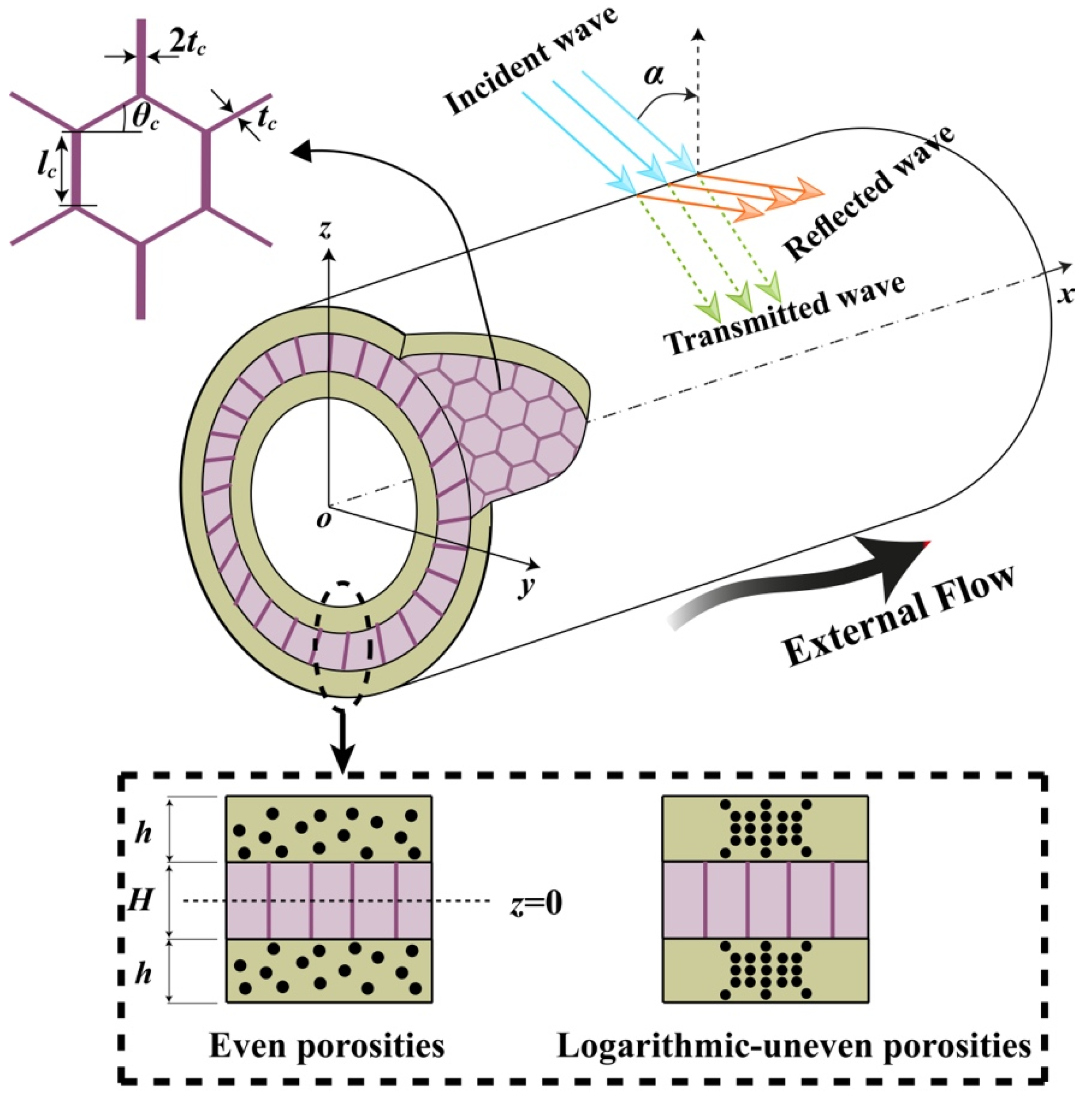
2. Mathematical Model
2.1. Acoustic Equation of Fluids
2.2. Equations of Motion
2.3. Continuity Conditions of Fluid/Structure
3. STL
4. Numerical Results and Discussion
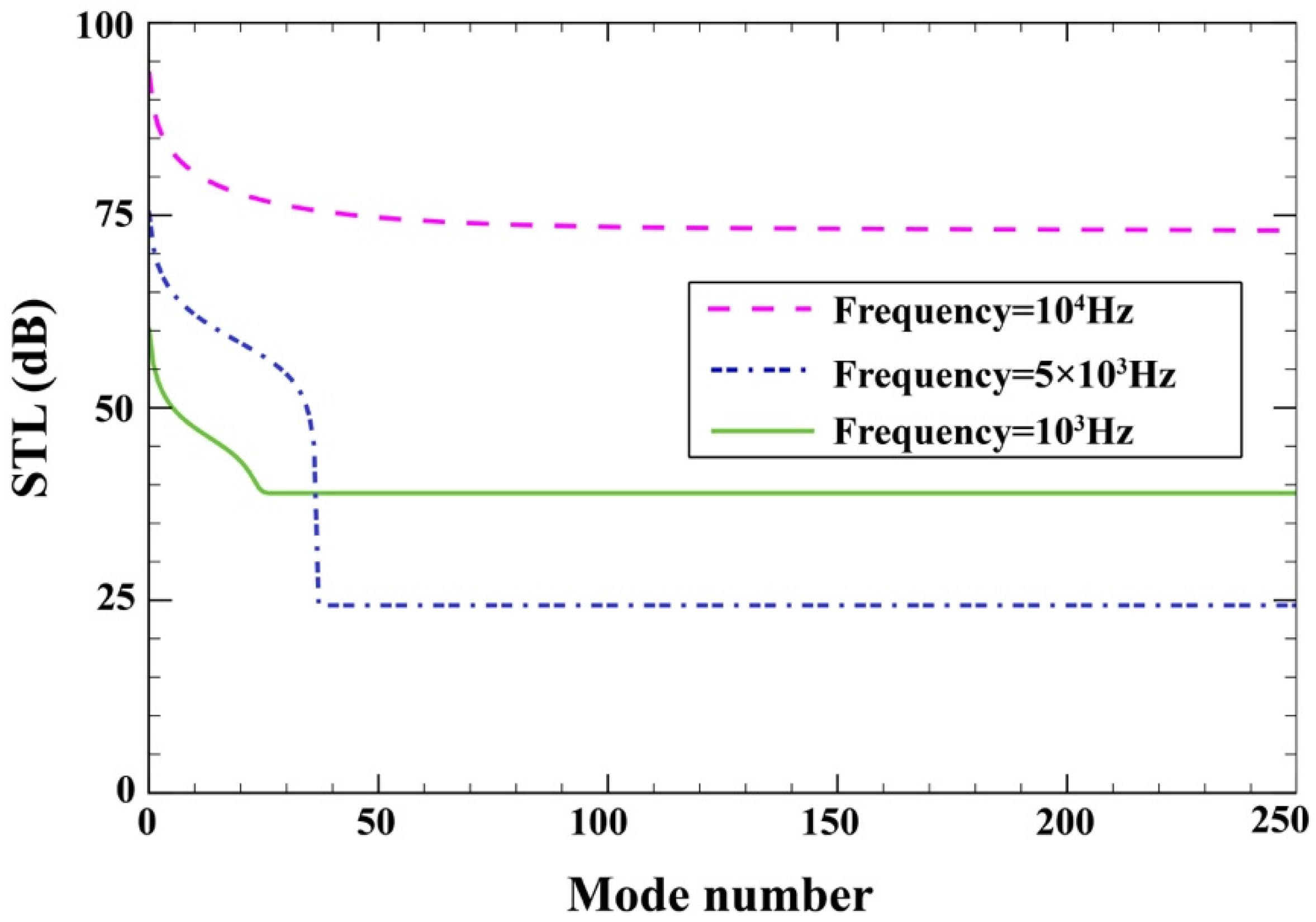
4.1. Mode Convergence
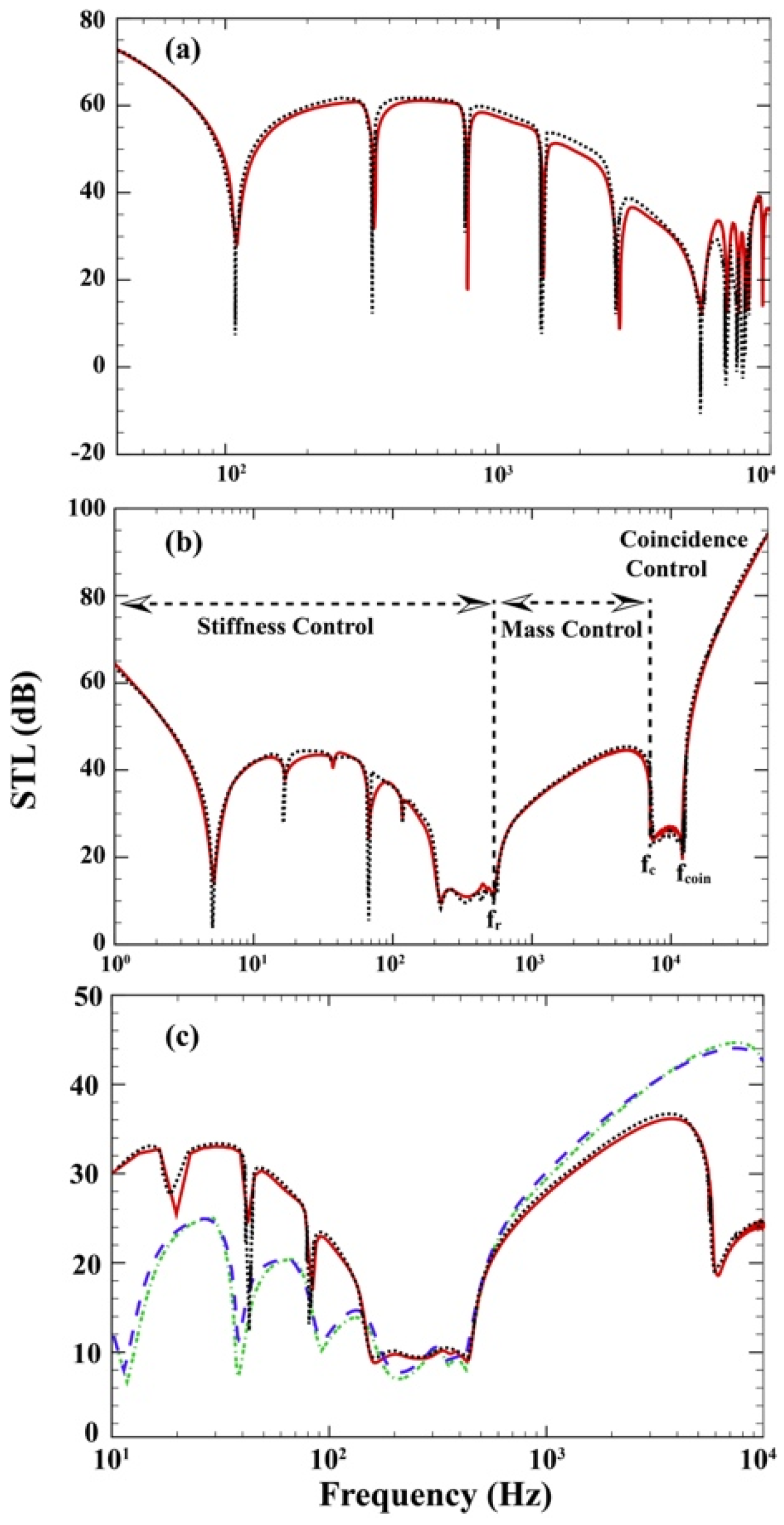
4.2. Comparison Study
4.3. Parametric Study
5. Conclusions
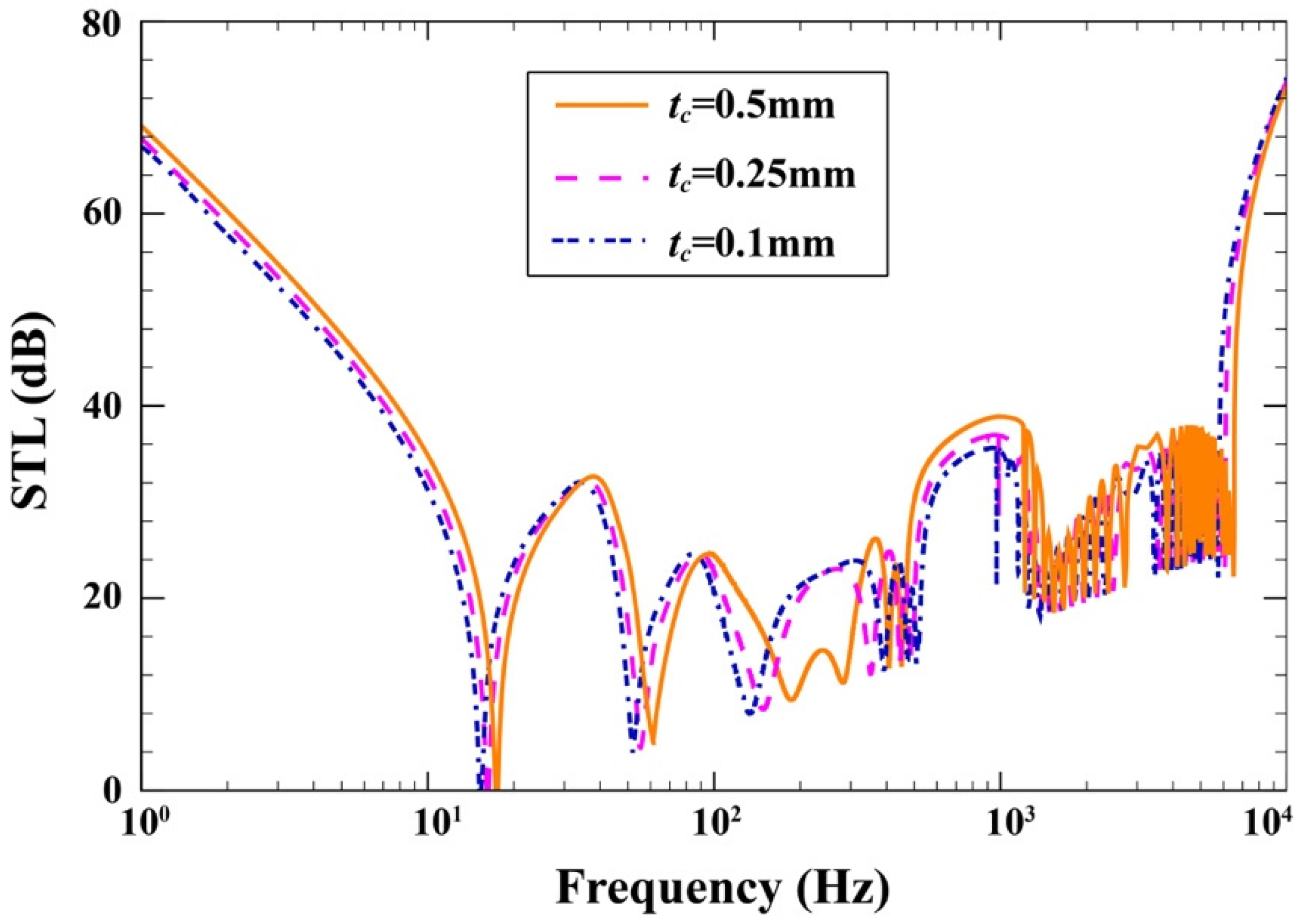
- The increase in the wall thickness of each honeycomb cell increases the core stiffness, so that STL grows.
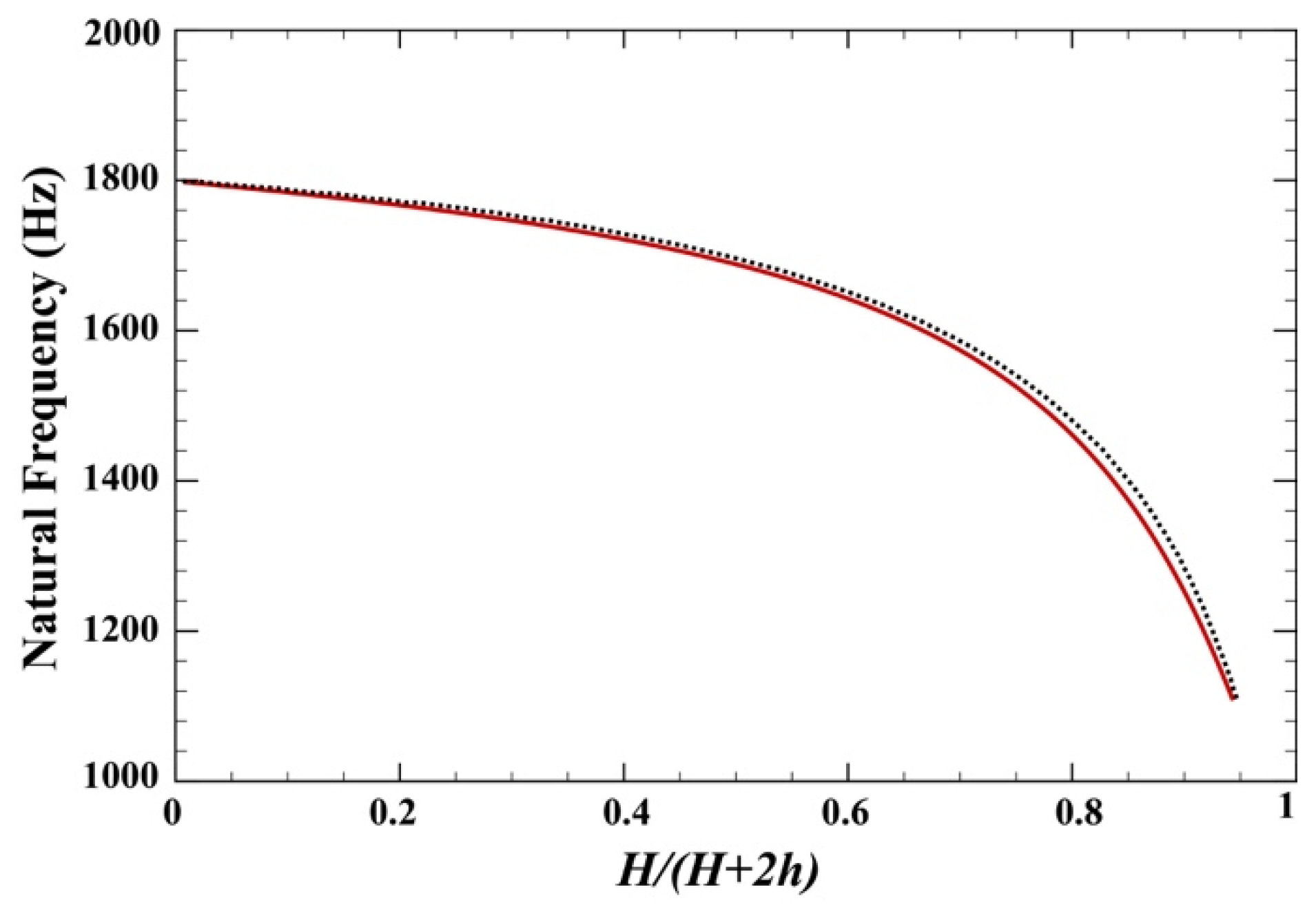
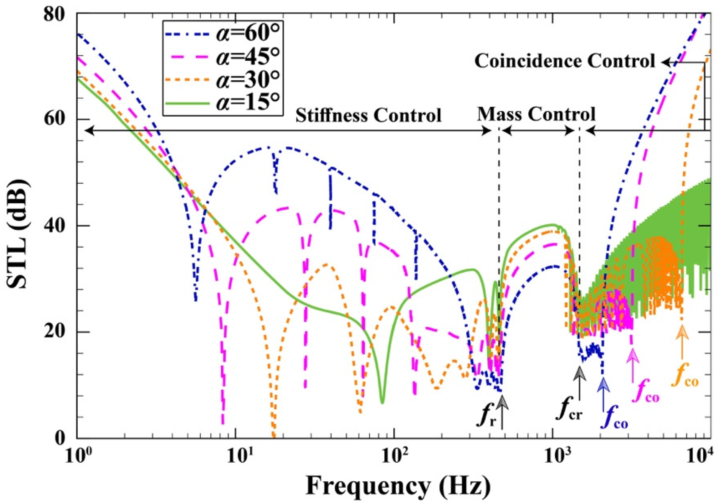
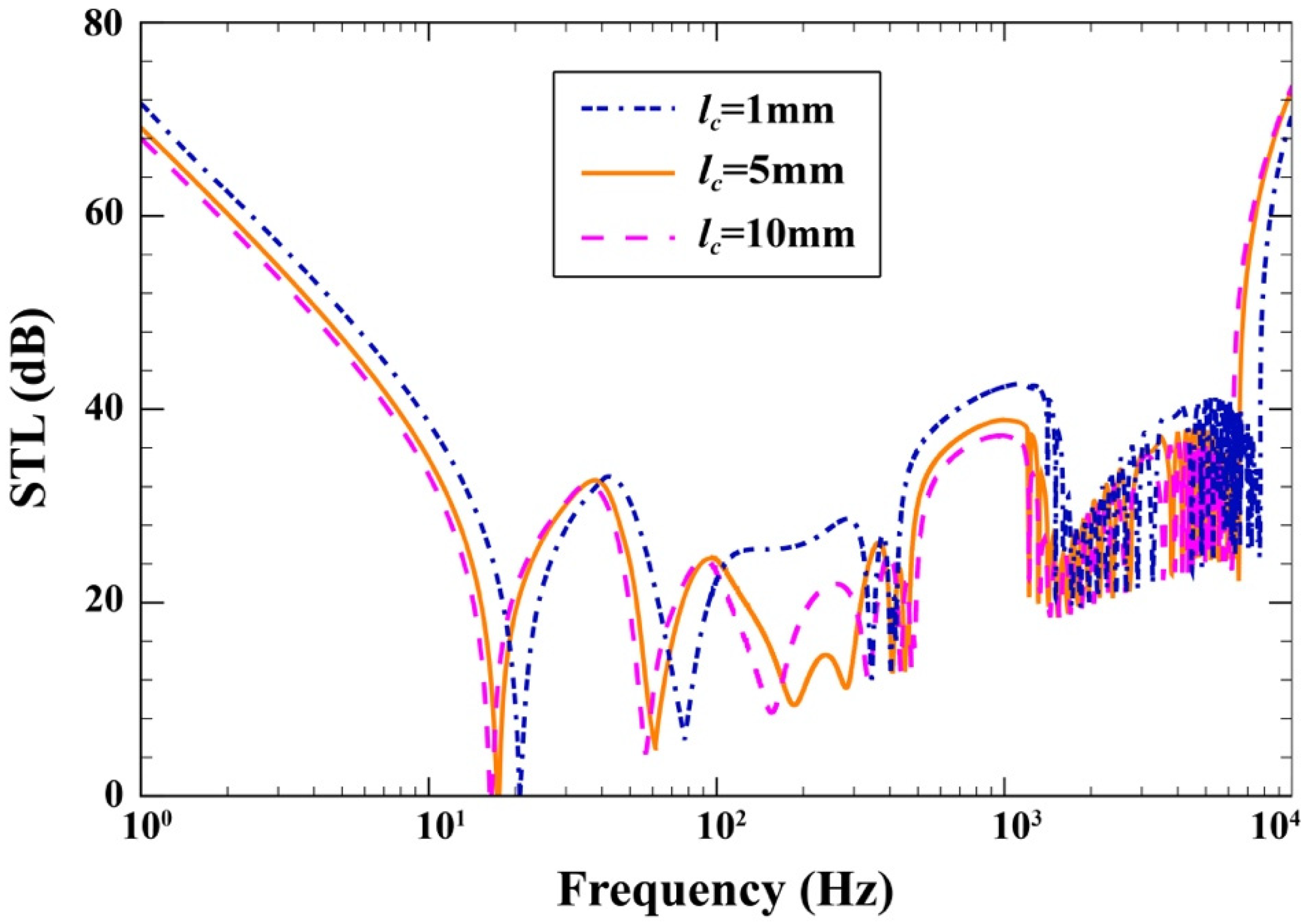
- Decreasing the value of concurrently increases the elastic modulus, total bending stiffness, and structure’s density, which increases STL in the stiffness-controlled and mass-controlled regions.
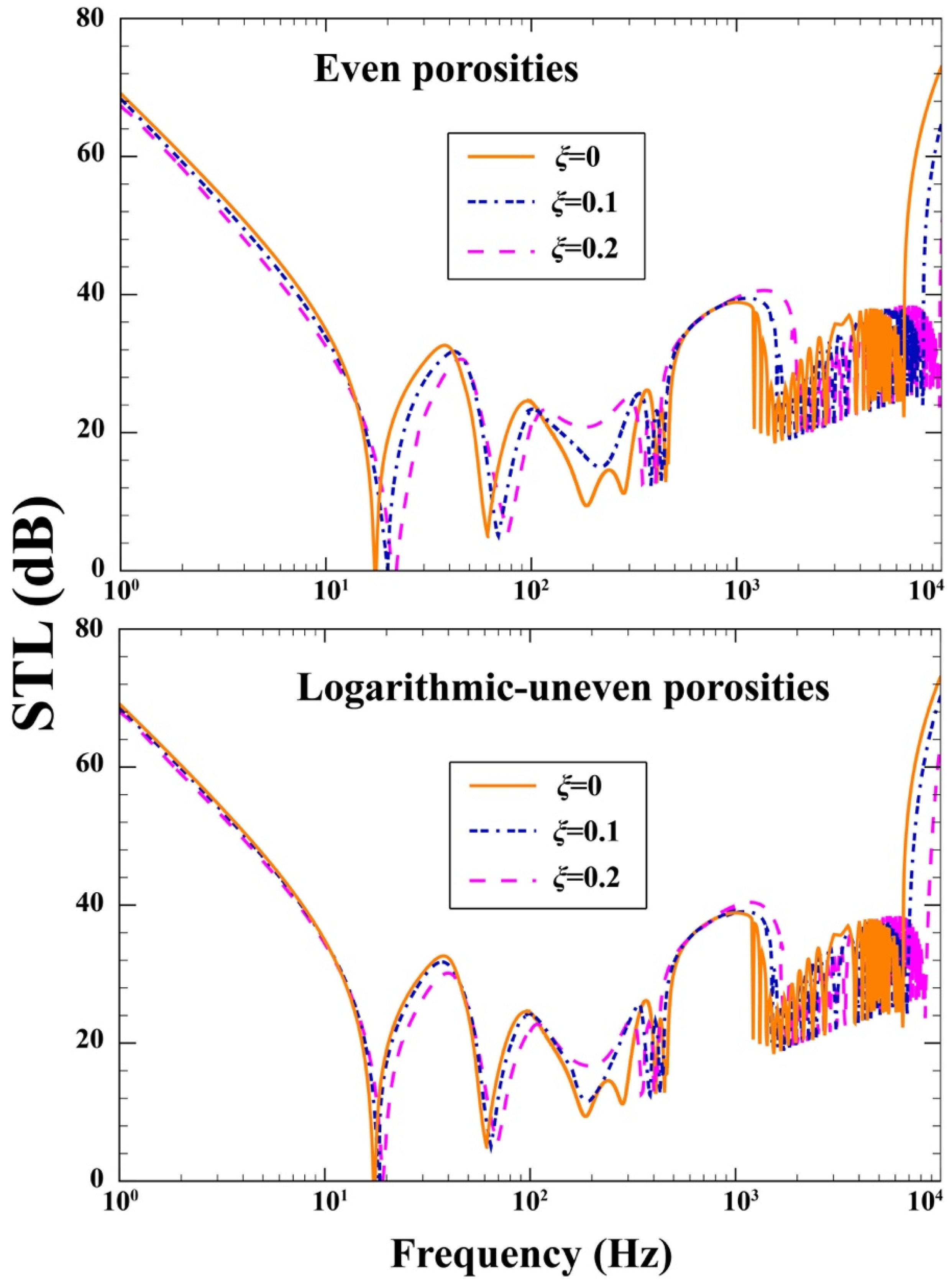
- STL reduces with growing porosity coefficient irrespective of porosity pattern.
- Higher levels of STL were obtained for the case of logarithmic-uneven distribution as it possesses a higher stiffness than even porosity distribution.
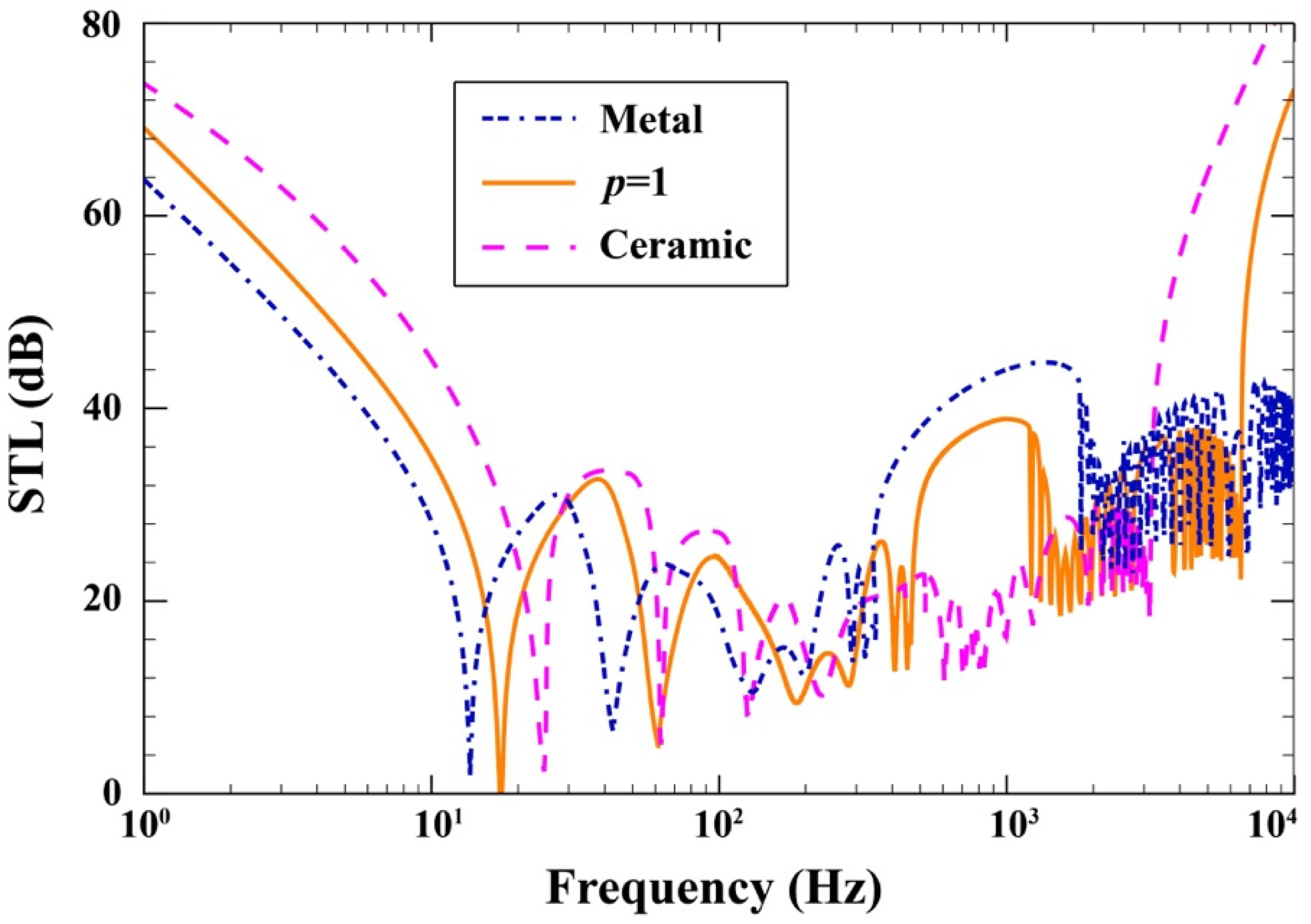
- Reducing the FG index, i.e., attaining a stronger ceramic behavior instead of metallic behavior, is one way to increase STL in the stiffness-controlled region.
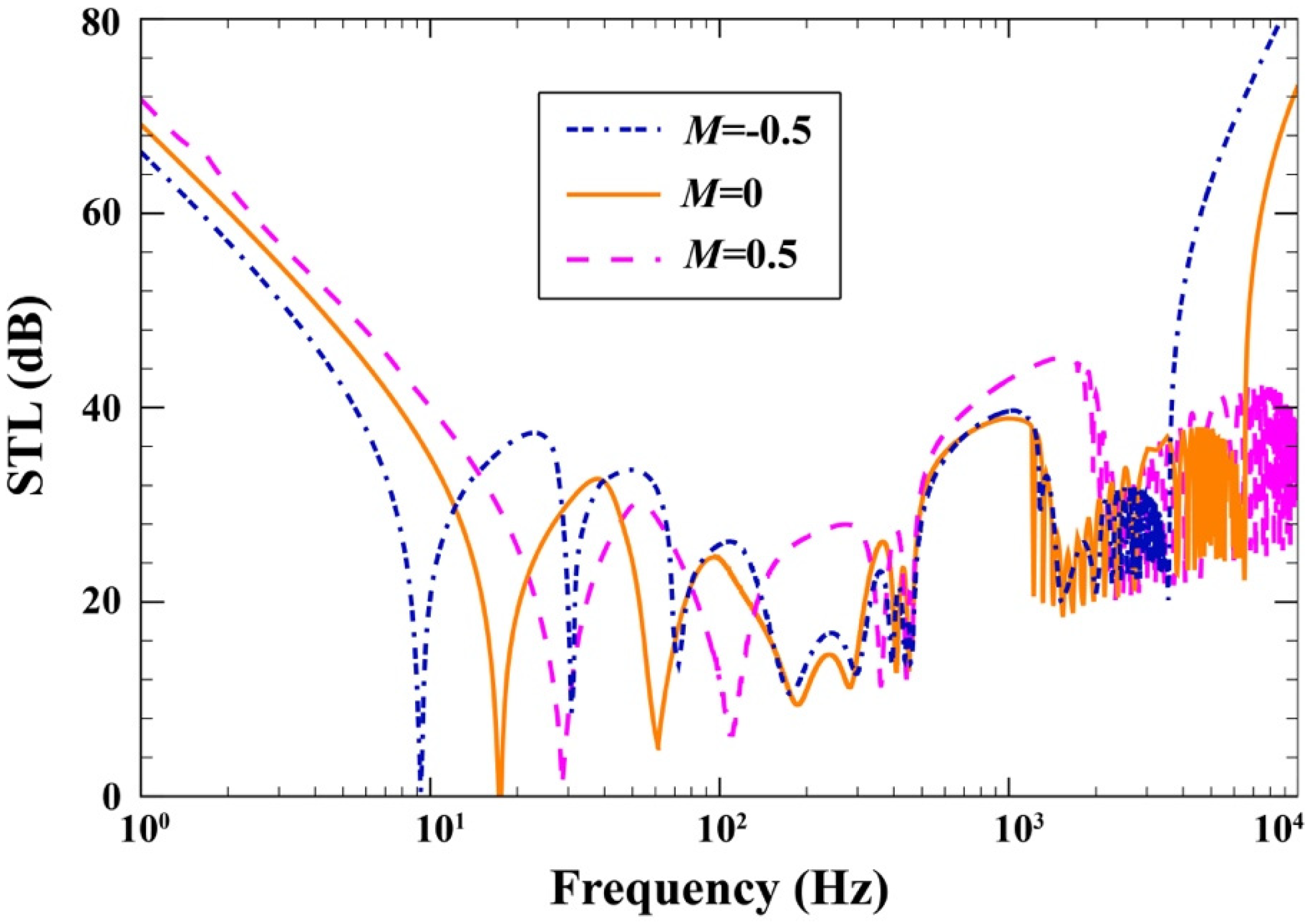
- The radiation damping after has the capability of increasing STL with a growing Mach number.
Author Contributions
Funding
Institutional Review Board Statement
Informed Consent Statement
Data Availability Statement
Acknowledgments
Conflicts of Interest
Appendix A
Appendix B
References
- Funari, M.F.; Spadea, S.; Lonetti, P.; Lourenço, P.B. On the elastic and mixed-mode fracture properties of PVC foam. Theor. Appl. Fract. Mech. 2021, 112, 102924. [Google Scholar] [CrossRef]
- Funari, M.F.; Greco, F.; Lonetti, P. Sandwich panels under interfacial debonding mechanisms. Compos. Struct. 2018, 203, 310–320. [Google Scholar] [CrossRef]
- Atas, C.; Sevim, C. On the impact response of sandwich composites with cores of balsa wood and PVC foam. Compos. Struct. 2010, 93, 40–48. [Google Scholar] [CrossRef]
- Bruno, D.; Fabbrocino, F.; Funari, M.F.; Greco, F.; Lonetti, P.; Spadea, S. An Experimental and Numerical Study to Evaluate the Crack Path Under Mixed Mode Loading on Pvc Foams. In Conference of the Italian Association of Theoretical and Applied Mechanics; Springer: Berlin/Heidelberg, Germany, 2019; pp. 378–388. [Google Scholar]
- Balcı, O.; Çoban, O.; Bora, M.Ö.; Akagündüz, E.; Yalçin, E.B. Experimental investigation of single and repeated impacts for repaired honeycomb sandwich structures. Mater. Sci. Eng. A 2017, 682, 23–30. [Google Scholar] [CrossRef]
- Li, Y.; Jin, Z. Free flexural vibration analysis of symmetric rectangular honeycomb panels with SCSC edge supports. Compos. Struct. 2008, 83, 154–158. [Google Scholar] [CrossRef]
- Yongqiang, L.; Feng, L.; Dawei, Z. Geometrically nonlinear free vibrations of the symmetric rectangular honeycomb sandwich panels with simply supported boundaries. Compos. Struct. 2010, 92, 1110–1119. [Google Scholar] [CrossRef]
- Duc, N.D.; Seung-Eock, K.; Tuan, N.D.; Tran, P.; Khoa, N.D. New approach to study nonlinear dynamic response and vibration of sandwich composite cylindrical panels with auxetic honeycomb core layer. Aerosp. Sci. Technol. 2017, 70, 396–404. [Google Scholar] [CrossRef]
- Duc, N.D.; Seung-Eock, K.; Cong, P.H.; Anh, N.T.; Khoa, N.D. Dynamic response and vibration of composite double curved shallow shells with negative Poisson’s ratio in auxetic honeycombs core layer on elastic foundations subjected to blast and damping loads. Int. J. Mech. Sci. 2017, 133, 504–512. [Google Scholar] [CrossRef]
- Li, Y.; Yao, W.; Wang, T. Free flexural vibration of thin-walled honeycomb sandwich cylindrical shells. Thin-Walled Struct. 2020, 157, 107032. [Google Scholar] [CrossRef]
- Eipakchi, H.; Nasrekani, F.M. Vibrational behavior of composite cylindrical shells with auxetic honeycombs core layer subjected to a moving pressure. Compos. Struct. 2020, 254, 112847. [Google Scholar] [CrossRef]
- Van Quyen, N.; Van Thanh, N.; Quan, T.Q.; Duc, N.D. Nonlinear forced vibration of sandwich cylindrical panel with negative Poisson’s ratio auxetic honeycombs core and CNTRC face sheets. Thin-Walled Struct. 2021, 162, 107571. [Google Scholar] [CrossRef]
- Koval, L.R. On sound transmission into a thin cylindrical shell under “flight conditions”. J. Sound Vib. 1976, 48, 265–275. [Google Scholar] [CrossRef]
- Lee, J.-H.; Kim, J. Analysis and measurement of sound transmission through a double-walled cylindrical shell. J. Sound Vib. 2002, 251, 631–649. [Google Scholar] [CrossRef]
- Talebitooti, R.; Choudari Khameneh, A.M.; Zarastvand, M.R.; Kornokar, M. Investigation of three-dimensional theory on sound transmission through compressed poroelastic sandwich cylindrical shell in various boundary configurations. J. Sandw. Struct. Mater. 2019, 21, 2313–2357. [Google Scholar] [CrossRef]
- Daneshjou, K.; Nouri, A.; Talebitooti, R. Sound transmission through laminated composite cylindrical shells using analytical model. Arch. Appl. Mech. 2007, 77, 363–379. [Google Scholar] [CrossRef]
- Kerboua, Y.; Lakis, A.A. Numerical model to analyze the aerodynamic behavior of a combined conical–cylindrical shell. Aerosp. Sci. Technol. 2016, 58, 601–617. [Google Scholar] [CrossRef]
- Ebrahimi, F.; Hashemabadi, D.; Habibi, M.; Safarpour, H. Thermal buckling and forced vibration characteristics of a porous GNP reinforced nanocomposite cylindrical shell. Microsyst. Technol. 2020, 26, 461–473. [Google Scholar] [CrossRef]
- Thongchom, C.; Refahati, N.; Saffari, P.R.; Saffari, P.R.; Niyaraki, M.N.; Sirimontree, S.; Keawsawasvong, S. An Experimental Study on the Effect of Nanomaterials and Fibers on the Mechanical Properties of Polymer Composites. Buildings 2022, 12, 7. [Google Scholar] [CrossRef]
- Deng, J.; Guasch, O.; Maxit, L.; Zheng, L. Vibration of cylindrical shells with embedded annular acoustic black holes using the Rayleigh-Ritz method with Gaussian basis functions. Mech. Syst. Signal Process. 2021, 150, 107225. [Google Scholar] [CrossRef]
- Roodgar Saffari, P.; Fakhraie, M.; Roudbari, M.A. Free vibration problem of fluid-conveying double-walled boron nitride nanotubes via nonlocal strain gradient theory in thermal environment. Mech. Based Des. Struct. Mach. 2020, 1–18. [Google Scholar] [CrossRef]
- Zarabimanesh, Y.; Roodgar Saffari, P.; Roudgar Saffari, P.; Refahati, N. Hygro-thermo-mechanical vibration of two vertically aligned single-walled boron nitride nanotubes conveying fluid. J. Vib. Control 2021. [Google Scholar] [CrossRef]
- Roodgar Saffari, P.; Fakhraie, M.; Roudbari, M.A. Size-Dependent Vibration Problem of Two Vertically-Aligned Single-Walled Boron Nitride Nanotubes Conveying Fluid in Thermal Environment Via Nonlocal Strain Gradient Shell Model. J. Solid Mech. 2021, 13, 164–185. [Google Scholar]
- Saffari, P.R.; Fakhraie, M.; Roudbari, M.A. Nonlinear vibration of fluid conveying cantilever nanotube resting on visco-pasternak foundation using non-local strain gradient theory. Micro. Nano Lett. 2020, 15, 181–186. [Google Scholar] [CrossRef]
- Hosseini, M.; Jamalpoor, A. Analytical Solution for Thermomechanical Vibration of Double-Viscoelastic Nanoplate-Systems Made of Functionally Graded Materials. J. Therm. Stress 2015, 38, 1428–1456. [Google Scholar] [CrossRef]
- Mahamood, R.M.; Akinlabi, E.T.; Shukla, M.; Pityana, S. Functionally Graded Material: An Overview. In Proceedings of the World Congress on Engineering 2012 Vol III (WCE 2012), London, UK, 4–6 July 2012. [Google Scholar]
- Belabed, Z.; Houari, M.S.A.; Tounsi, A.; Mahmoud, S.R.; Bég, O.A. An efficient and simple higher order shear and normal deformation theory for functionally graded material (FGM) plates. Compos. Part. B Eng. 2012, 60, 274–283. [Google Scholar] [CrossRef]
- Hosseini, M.; Jamalpoor, A.; Fath, A. Surface effect on the biaxial buckling and free vibration of FGM nanoplate embedded in visco-Pasternak standard linear solid-type of foundation. Meccanica 2017, 52, 1381–1396. [Google Scholar] [CrossRef]
- Hosseini, M.; Bahreman, M.; Jamalpoor, A. Thermomechanical vibration analysis of FGM viscoelastic multi-nanoplate system incorporating the surface effects via nonlocal elasticity theory. Microsyst. Technol. 2017, 23, 3041–3058. [Google Scholar] [CrossRef]
- Roodgar Saffari, P.; Fakhraie, M.; Roudbari, M.A. Free Vibration and Transient Response of Heterogeneous Piezoelectric Sandwich Annular Plate Using Third-Order Shear Deformation Assumption. J. Solid Mech. 2020, 12, 315–333. [Google Scholar] [CrossRef]
- Kato, K.; Kurimoto, M.; Shumiya, H.; Adachi, H.; Sakuma, S.; Okubo, H. Application of functionally graded material for solid insulator in gaseous insulation system. IEEE Trans. Dielectr. Electr. Insul. 2006, 13, 362–372. [Google Scholar] [CrossRef]
- Sinha, G.P.; Kumar, B. Review on vibration analysis of functionally graded material structural components with cracks. J. Vib. Eng. Technol. 2021, 9, 23–49. [Google Scholar] [CrossRef]
- Yılmaz, E.; Kabataş, F.; Gökçe, A.; Fındık, F. Production and Characterization of a Bone-Like Porous Ti/Ti-Hydroxyapatite Functionally Graded Material. J. Mater. Eng. Perform. 2020, 29, 6455–6467. [Google Scholar] [CrossRef]
- Loy, C.T.; Lam, K.Y.; Reddy, J.N. Vibration of functionally graded cylindrical shells. Int. J. Mech. Sci. 1999, 41, 309–324. [Google Scholar] [CrossRef]
- Pradhan, S.C.; Loy, C.T.; Lam, K.Y.; Reddy, J.N. Vibration characteristics of functionally graded cylindrical shells under various boundary conditions. Appl. Acoust. 2000, 61, 111–129. [Google Scholar] [CrossRef]
- Liu, T.; Wang, A.; Wang, Q.; Qin, B. Wave based method for free vibration characteristics of functionally graded cylindrical shells with arbitrary boundary conditions. Thin-Walled Struct. 2020, 148, 106580. [Google Scholar] [CrossRef]
- Wang, Y.; Ye, C.; Zu, J.W. Identifying the temperature effect on the vibrations of functionally graded cylindrical shells with porosities. Appl. Math. Mech. 2018, 39, 1587–1604. [Google Scholar] [CrossRef]
- Baghlani, A.; Khayat, M.; Dehghan, S.M. Free vibration analysis of FGM cylindrical shells surrounded by Pasternak elastic foundation in thermal environment considering fluid-structure interaction. Appl. Math. Model. 2020, 78, 550–575. [Google Scholar] [CrossRef]
- Sofiyev, A.H. Dynamic response of an FGM cylindrical shell under moving loads. Compos. Struct. 2010, 93, 58–66. [Google Scholar] [CrossRef]
- Baghbadorani, A.A.; Kiani, Y. Free vibration analysis of functionally graded cylindrical shells reinforced with graphene platelets. Compos. Struct. 2021, 276, 114546. [Google Scholar] [CrossRef]
- Nguyen, T.P.; Nguyen-Thoi, T.; Tran, D.K.; Ho, D.T.; Vu, H.N. Nonlinear vibration of full-filled fluid corrugated sandwich functionally graded cylindrical shells. J. Vib. Control 2021, 27, 1020–1035. [Google Scholar] [CrossRef]
- Ni, Y.; Zhu, S.; Sun, J.; Tong, Z.; Zhou, Z.; Xu, X.; Lim, C.W. An accurate model for free vibration of porous magneto-electro-thermo-elastic functionally graded cylindrical shells subjected to multi-field coupled loadings. J. Intell. Mater. Syst. Struct. 2021, 32, 2006–2023. [Google Scholar] [CrossRef]
- Cong, P.H.; Duc, N.D. Nonlinear thermo-mechanical analysis of ES double curved shallow auxetic honeycomb sandwich shells with temperature-dependent properties. Compos. Struct. 2021, 279, 114739. [Google Scholar] [CrossRef]
- Rodrıguez-Castro, R.; Wetherhold, R.C.; Kelestemur, M.H. Microstructure and mechanical behavior of functionally graded Al A359/SiCp composite. Mater. Sci. Eng. A 2002, 323, 445–456. [Google Scholar] [CrossRef]
- Wang, Y.; Wu, D. Free vibration of functionally graded porous cylindrical shell using a sinusoidal shear deformation theory. Aerosp. Sci. Technol. 2017, 66, 83–91. [Google Scholar] [CrossRef]
- Cuong-Le, T.; Nguyen, K.D.; Nguyen-Trong, N.; Khatir, S.; Nguyen-Xuan, H.; Abdel-Wahab, M. A three-dimensional solution for free vibration and buckling of annular plate, conical, cylinder and cylindrical shell of FG porous-cellular materials using IGA. Compos. Struct. 2021, 259, 113216. [Google Scholar] [CrossRef]
- Shahgholian, D.; Safarpour, M.; Rahimi, A.R.; Alibeigloo, A. Buckling analyses of functionally graded graphene-reinforced porous cylindrical shell using the Rayleigh–Ritz method. Acta Mech. 2020, 231, 1887–1902. [Google Scholar] [CrossRef]
- Ghadiri, M.; Safar Pour, H. Free vibration analysis of size-dependent functionally graded porous cylindrical microshells in thermal environment. J. Therm. Stress 2017, 40, 55–71. [Google Scholar] [CrossRef]
- Keleshteri, M.M.; Jelovica, J. Nonlinear vibration behavior of functionally graded porous cylindrical panels. Compos. Struct. 2020, 239, 112028. [Google Scholar] [CrossRef]
- Li, Z.; Zhong, R.; Wang, Q.; Qin, B.; Yu, H. The thermal vibration characteristics of the functionally graded porous stepped cylindrical shell by using characteristic orthogonal polynomials. Int. J. Mech. Sci. 2020, 182, 105779. [Google Scholar] [CrossRef]
- Hasheminejad, S.M.; Jamalpoor, A. Sound transmission control through a hybrid smart double sandwich plate structure. J. Sandw. Struct. Mater. 2021, 23, 2443–2483. [Google Scholar] [CrossRef]
- Heckl, M. The tenth Sir Richard Fairey memorial lecture: Sound transmission in buildings. J. Sound Vib. 1981, 77, 165–189. [Google Scholar] [CrossRef]
- Pellicier, A.; Trompette, N. A review of analytical methods, based on the wave approach, to compute partitions transmission loss. Appl. Acoust. 2007, 68, 1192–1212. [Google Scholar] [CrossRef]
- Ramezani, H.; Talebitooti, R. Vibroacoustic response of a double-walled cylindrical FGM shell with a porous sandwiched layer. Mech. Compos. Mater. 2015, 51, 581–592. [Google Scholar] [CrossRef]
- Daneshjou, K.; Talebitooti, R.; Tarkashvand, A. Analysis of sound transmission loss through thick-walled cylindrical shell using three-dimensional elasticity theory. Int. J. Mech. Sci. 2016, 106, 286–296. [Google Scholar] [CrossRef]
- Oliazadeh, P.; Farshidianfar, A. Analysis of different techniques to improve sound transmission loss in cylindrical shells. J. Sound Vib. 2017, 389, 276–291. [Google Scholar] [CrossRef]
- Ahmadi, M.; Talebitooti, M.; Talebitooti, R. Analytical investigation on sound transmission loss of functionally graded nanocomposite cylindrical shells reinforced by carbon nanotubes. Mech. Based Des. Struct. Mach. 2020, 1–18. [Google Scholar] [CrossRef]
- Hasheminejad, S.M.; Cheraghi, M.; Jamalpoor, A. Active damping of sound transmission through an electrorheological fluid-actuated sandwich cylindrical shell. J. Sandw. Struct. Mater. 2020, 22, 833–865. [Google Scholar] [CrossRef]
- Fu, T.; Wu, X.; Xiao, Z.; Chen, Z. Thermoacoustic response of porous FGM cylindrical shell surround by elastic foundation subjected to nonlinear thermal loading. Thin-Walled Struct. 2020, 156, 106996. [Google Scholar] [CrossRef]
- Hasheminejad, S.M.; Jamalpoor, A. Control of sound transmission into a hybrid double-wall sandwich cylindrical shell. J. Vib. Control 2021. [Google Scholar] [CrossRef]
- Li, F.; Yuan, W.; Zhang, C. Free vibration and sound insulation of functionally graded honeycomb sandwich plates. J. Sandw. Struct. Mater. 2021, 24, 565–600. [Google Scholar] [CrossRef]
- Daneshjou, K.; Nouri, A.; Talebitooti, R. Analytical model of sound transmission through orthotropic cylindrical shells with subsonic external flow. Aerosp. Sci. Technol. 2009, 13, 18–26. [Google Scholar] [CrossRef]
- Zhou, J.; Bhaskar, A.; Zhang, X. The effect of external mean flow on sound transmission through double-walled cylindrical shells lined with poroelastic material. J. Sound Vib. 2014, 333, 1972–1990. [Google Scholar] [CrossRef]
- Hosseini, M.; Mofidi, M.R.; Jamalpoor, A.; Jahanshahi, M.S. Nanoscale mass nanosensor based on the vibration analysis of embedded magneto-electro-elastic nanoplate made of FGMs via nonlocal Mindlin plate theory. Microsyst. Technol. 2018, 24, 2295–2316. [Google Scholar] [CrossRef] [Green Version]
- Kreja, I.; Schmidt, R.; Reddy, J.N. Finite elements based on a first-order shear deformation moderate rotation shell theory with applications to the analysis of composite structures. Int. J. Non Linear Mech. 1997, 32, 1123–1142. [Google Scholar] [CrossRef]
- Amabili, M. Nonlinear Vibrations and Stability of Shells and Plates; Cambridge University Press: Cambridge, UK, 2008. [Google Scholar]
- Liu, Y.; He, C. Diffuse field sound transmission through sandwich composite cylindrical shells with poroelastic core and external mean flow. Compos. Struct. 2016, 135, 383–396. [Google Scholar] [CrossRef]
- Kiani, A.; Sheikhkhoshkar, M.; Jamalpoor, A.; Khanzadi, M. Free vibration problem of embedded magneto-electro-thermo-elastic nanoplate made of functionally graded materials via nonlocal third-order shear deformation theory. J. Intell Mater. Syst. Struct. 2018, 29, 741–763. [Google Scholar] [CrossRef]
- Nikrad, S.F.; Kanellopoulos, A.; Bodaghi, M.; Chen, Z.T.; Pourasghar, A. Large deformation behavior of functionally graded porous curved beams in thermal environment. Arch. Appl. Mech. 2021, 91, 2255–2278. [Google Scholar] [CrossRef]
- Hasheminejad, S.M.; Jamalpoor, A. Cancelation of acoustic scattering from a smart hybrid ERF/PZT-based double-wall composite spherical shell structure. Mech. Adv. Mater. Struct. 2021, 1–22. [Google Scholar] [CrossRef]
- Talebitooti, R.; Zarastvand, M.R.; Gheibi, M.R. Acoustic transmission through laminated composite cylindrical shell employing Third order Shear Deformation Theory in the presence of subsonic flow. Compos. Struct. 2016, 157, 95–110. [Google Scholar] [CrossRef]
- Reaei, S.; Tarkashvand, A.; Talebitooti, R. Applying a functionally graded viscoelastic model on acoustic wave transmission through the polymeric foam cylindrical shell. Compos. Struct. 2020, 244, 112261. [Google Scholar] [CrossRef]


| Properties | Alumina (Ceramic) | Steel (Metal) |
| Elastic (GPa) | ||
| Poisson’s Ratio | ||
| Mass density ( ) | ||
| Properties (Acoustic Medium) | Air | |
| Sound Speed () | ||
| Mass density ( ) | ||
| Present | Ref. [24] | ||
|---|---|---|---|
| 0 | 1 | 12.905 | 12.917 |
| 2 | 31.578 | 31.603 | |
| 3 | 88.002 | 88.267 | |
| 1 | 1 | 13.189 | 13.234 |
| 2 | 32.267 | 32.418 | |
| 3 | 90.345 | 90.569 | |
| 2 | 1 | 13.317 | 13.344 |
| 2 | 32.549 | 32.683 | |
| 3 | 91.066 | 91.309 |
Publisher’s Note: MDPI stays neutral with regard to jurisdictional claims in published maps and institutional affiliations. |
© 2022 by the authors. Licensee MDPI, Basel, Switzerland. This article is an open access article distributed under the terms and conditions of the Creative Commons Attribution (CC BY) license (https://creativecommons.org/licenses/by/4.0/).
Share and Cite
Thongchom, C.; Jearsiripongkul, T.; Refahati, N.; Roudgar Saffari, P.; Roodgar Saffari, P.; Sirimontree, S.; Keawsawasvong, S. Sound Transmission Loss of a Honeycomb Sandwich Cylindrical Shell with Functionally Graded Porous Layers. Buildings 2022, 12, 151. https://doi.org/10.3390/buildings12020151
Thongchom C, Jearsiripongkul T, Refahati N, Roudgar Saffari P, Roodgar Saffari P, Sirimontree S, Keawsawasvong S. Sound Transmission Loss of a Honeycomb Sandwich Cylindrical Shell with Functionally Graded Porous Layers. Buildings. 2022; 12(2):151. https://doi.org/10.3390/buildings12020151
Chicago/Turabian StyleThongchom, Chanachai, Thira Jearsiripongkul, Nima Refahati, Peyman Roudgar Saffari, Pouyan Roodgar Saffari, Sayan Sirimontree, and Suraparb Keawsawasvong. 2022. "Sound Transmission Loss of a Honeycomb Sandwich Cylindrical Shell with Functionally Graded Porous Layers" Buildings 12, no. 2: 151. https://doi.org/10.3390/buildings12020151