Article

Frequency Domain Analysis of Alongwind Response and Study of Wind Loads for Transmission Tower Subjected to Downbursts

1
Chongqing Key Laboratory of Energy Engineering Mechanics & Disaster Prevention and Mitigation, Chongqing University of Science and Technology, Chongqing 401331, China
2
School of Civil Engineering and Architecture, Chongqing University of Science and Technology, Chongqing 401331, China
*
Author to whom correspondence should be addressed.
Buildings 2022, 12(2), 148; https://doi.org/10.3390/buildings12020148
Submission received: 16 December 2021 / Revised: 25 January 2022 / Accepted: 26 January 2022 / Published: 31 January 2022

Abstract

:
Downburst is one of the high-intensity winds that cause transmission tower failures. The regulations of transmission tower-line systems under downburst wind loads cannot meet the design requirements at present. In this paper, the calculation formulas of the background and resonant components of transmission tower under downburst wind loads are obtained, based on the modal analysis theory of non-stationary wind for the single-degree-of-freedom system in the frequency domain. The effects of structural dynamic characteristics, damping ratio, and mean wind speed vertical profile on dynamic effect on structural response are discussed. Then the equivalent static wind load (ESWL) is obtained according to the maximum response and compared with the finite element method (FEM) in the time domain. Applications of these formulas are addressed to the cases from the empirical model of Holmes and field record of a rear flank downdraft (RFD). The results show that the maximum responses obtained by the current formulas match well with those from the modal decomposition method and dynamic analysis with FEM. The internal forces of tower members calculated by ESWL based on maximum response are closer to the results from FEM than those calculated by downburst loads recommended in ASCE guidelines. The presented framework can be used to assist the wind-resistant design of transmission towers considering downburst wind load.

1. Introduction

Electricity is transported from the source of power generation to end customers by transmission lines (TLs). Transmission towers are an important part of TLs and are very sensitive to wind loads. In the past few decades, high-intensity winds (HIW), such as downbursts and tornados, caused a large number of failures to transmission towers around the world [1,2,3]. A downburst is a strong downdraft that induces an outward burst of damaging winds on or near the ground, and its maximum wind speed can exceed 60 m/s [4]. The characteristics of downbursts, including the vertical profile of mean velocity and other statistical characteristics, are very different from the atmospheric boundary layer (ABL). The maximum velocity of downburst outflow occurs near ground level and decreases with further increase in height, while the ABL profile increases monotonically with height and is commonly modeled with either a power or logarithmic law equation. In addition, downburst outflow is highly non-stationary and may cause very different responses of structures. At present, the main loads considered in the design of transmission tower-line structures are based on the ABL wind loads. This design principle may result in transmission towers being not able to resist HIW, such as downbursts. Although downburst is one of the main reasons for a large number of failure incidents to transmission towers, the research on the wind-induced vibration response of the transmission tower under downburst wind loading cannot meet the design requirements at present.
The time-domain method is widely used to study the wind-induced vibration of structures under the downburst due to its non-stationary characteristics. Field measurement is the most direct and reliable way to obtain wind data of downburst outflow [5,6,7,8]. However, due to the short duration and small size of the downburst, it is very difficult for the on-site measurements to give the available data needed for structural analysis [9]. The wind tunnel test is also an important way to study the characteristics of downburst wind field [10,11,12,13], but the scale of the wind tunnel test is usually small. Hence, there are two main ways to obtain the wind speed time history of downbursts in the time-domain analysis: the analytical model and computational fluid dynamics (CFD). These numerical simulations are also validated by experimental data or full-scale field measurement records. Based on the empirical model proposed by Holmes and Oliver [14], Savory et al. [15] analyzed the failures of transmission towers due to (HIW). There are many simplifications for aerodynamic wind load and corresponding tower structure in their analysis. The downburst is modeled as a quasi-steady event without the fluctuation component. Chen and Letchford [16] presented a deterministic-stochastic hybrid model of downbursts. The generated stochastic fluctuation is used to investigate the dynamic responses of a cantilevered structure. This model was widely used in the dynamic studies of transmission towers subjected to downbursts [17,18,19]. Kim and Hangan [20] used an unsteady Reynolds-averaged Navier–Stokes (RANS) CFD model to simulate the spatial and time variations of the wind field associated with downbursts, based on the transient impinging circular jet approach. The simulations provide time series which compared well with the RFD full-scale data. Shehata et al. [21,22] and Shehata and El Damatty [23] obtained the time history of the downburst wind data through the CFD model of Kim and Hangan [20] and then analyzed the structural performance of a transmission tower. The coupling effect of the tower-line system was also considered. They found that the internal forces of the transmission tower members were related to the location of the downburst, nozzle diameter, and other parameters. With the numerical technique illustrated by Shehata et al. [21], researchers carried out a large number of studies on transmission towers under downburst wind loading [23,24,25,26,27,28,29]. These studies on transmission towers with the wind loads from the CFD model are in favor of neglecting the dynamic effects. This is due to some defects in the simulation of fluctuating wind speed by the turbulence model based on RANS. Because the time-averaging operation on the momentum equations discards all details concerning the state of the flow contained in the instantaneous fluctuations, Boussinesq visibility models (BVM) are used to simulate turbulence [30]. When RANS methodologies are applied to transient flows, the fluctuation component of velocity cannot be well simulated. In contrast to this, direct numerical simulation (DNS) and large eddy simulation (LES) are known to be viable approaches to simulate unsteady turbulent flows [31]. However, these simulations involve very high computational costs mostly for the large Reynolds number cases of downburst investigation [20]. In addition, two physical models for simulation of the downburst outflow—radial and plane wall jet —are particularly challenging cases for numerical turbulence models [32,33]. Although hybrid numerical approaches, such as detached eddy simulation (DES) [34,35] and scale adaptive simulation (SAS) [36], can improve the calculation efficiency with good accuracy, the time cost still cannot meet the requirements of the structural design. Therefore, the analytical model developed by Chen and Letchford [16] is used to obtain the wind speed time histories of a downburst in the present study.
There is little research on the frequency domain analysis of transmission towers under downburst wind loading due to the non-stationary characteristics. It is considered that there are many difficulties in analyzing the dynamic response under downburst in the frequency domain, and analysis in the time domain is the only option [37] However, Chen [38] proposed a framework to analyze the alongwind response of high-rise buildings to transient nonstationary winds in the frequency domain based on modal analysis. The nonstationary aerodynamic characteristics are expressed by aerodynamic admittance and joint acceptance function. This framework makes it possible to analyze transmission towers under downburst in the frequency domain. So far, this method has only been applied in the study of high-rise buildings [39,40,41] and has not been used in transmission towers. In addition, when the modal analysis method is used to calculate the structural dynamic response, the influence of cross-coupling cannot be ignored. At the same time, the natural frequency of most structures is greater than the forcing frequencies from wind loading, especially for the transmission tower. This leads to low efficiency of the modal analysis method. To overcome this problem, the dynamic response of the structure can be decomposed into the background and resonant components, respectively. This method is more effective and widely used in structural analysis under synoptic stationary winds. However, the method of separating background and resonant components has not been applied in the non-synoptic and non-stationary wind, such as downbursts.
Previous studies mostly focused on the wind-induced vibration response characteristics of transmission tower-line systems under downburst wind loading, and only a few studies investigated the methods for structural design. Although wind engineering researchers have proposed that downburst should be taken into account in structural design [42,43], only a few codes, such as the American Society of Civil Engineers [44] and Australian/New Zealand Standard [45], require that the effect of this strong wind loading should be considered in the structural design of transmission towers [46,47]. The wind loads standard issued by International Organization for Standardization [48] also includes the downburst wind loads and recommends the wind speed profile. Mara and Hong [49] used the nonlinear static pushover analysis to obtain the capacity curve of a self-support tower with the wind loads specified in CAN/CSA C22.3 No. 60826-10. The shape of the velocity profile they selected is rectangular (uniform), which is quite different from downbursts. Yang and Zhang [50] studied the wind loads of transmission towers under downburst wind loads according to ASCE guidelines and analyzed the bearing performance of members. They found that downburst is more destructive in inland areas with lower design winds. Zhao et al. [51] analyzed the dynamic response of a transmission tower under moving downbursts by FEM and put forward the formula of equivalent static wind load according to the inertia force method. Generally, there is still a considerable gap between the existing research works on downburst and the systematic guidance for the structural design.
Although researchers have made efforts to study the effect of transmission towers subjected to downburst, most published studies are in the time domain and conducted in a quasi-static manner. The research on the downburst wind loads for structural design is rare. This study aimed to (1) derive the calculation formulas of structural background and resonant response under downburst wind loading, based on the non-stationary modal analysis method, and (2) discuss the dynamic effect and design wind loads of downburst on the transmission tower. Following Section 1, Section 2 introduces the generation of non-stationary wind time-histories using the deterministic–stochastic hybrid model. In Section 3, a framework for calculating the background and resonant response of transmission towers under downburst wind loading is presented. Applications of this framework are addressed to transmission towers with different time functions. The effects of damping ratio, structural dynamic characteristics time-varying mean, and mean wind speed vertical profile are discussed. Section 4 derives the formulas of the equivalent static wind load corresponding to the maximum response under downburst wind loads. Then the static analyses of a transmission tower are carried out by using these formulas and the loads from ASCE [44], respectively. Section 5 summarizes the main findings of this study.

2. Downburst Loading on Lattice Towers

Generally, the wind speed of downburst at any height can be decomposed into a deterministic time-varying mean component and fluctuating component as follows [16,52]:
V z , t = V ¯ z , t + v z , t
where V z , t is the wind speed at time t and height z, V ¯ z , t is a deterministic time-varying mean component, and v z , t is a stochastic fluctuating component. The field observations show that downbursts are non-stationary processes, and most of them are traveling events [53,54]. Xhelaj et al. [55] proposed a novel analytical model to simulate the horizontal mean wind velocity at a fixed height above the ground for a traveling downburst. However, the model is only two-dimensional and cannot incorporate the variation of the wind speed with the height AGL. Therefore, it is not suitable for structural analysis. Canepa et al. [56] found that the strength of the downburst outflow suppresses the effects of the background wind based on the field measurement data. So, the effect of environmental wind is not considered in the current study. Assuming that the maximum time-varying mean wind speed at different heights is reached at the same time, the time-varying mean wind speed can be expressed as the product of a vertical mean wind profile and the time function as follows:
V ¯ z , t = U ( z ) × g ( t )
where U(z) is the vertical profile of the maximum mean wind speed and g(t) is a time function with a maximum value of 1. Oseguera and Bowles [57], Vicroy [58] and Wood et al. [13] proposed three empirical models of the vertical profile for downbursts. By choosing the parameters summarized in Table 1. Figure 1 shows the comparison between the wind profiles of three downburst models and that of the ABL. The wind profile of the ABL adopts the power law. In Table 1, r is the radial coordinate from the center of the downburst; R is the characteristic radius of the downburst ‘shaft’; z* is a characteristic height out of the boundary layer; ε is a characteristic height in the boundary layer; λ is a scaling factor; and δ is the vertical position where the wind speed is half of the maximum wind speed. The surface roughness coefficient α is 0.16, and the mean wind speed at 10 m height, U10, is 30 m/s for ABL. The nominal height of the atmospheric boundary layer Zg is 350 m for Exposure B [59].
It is generally accepted that the impinging jet is the logical similarity model of the downburst [60]. The length scale δ and velocity scale Umax are usually used to achieve self-similarity for the mean flow of impinging jet [61]. Compared with the model from Oseguera and Bowles [57], the model from Wood et al. [13] requires fewer parameters and uses the length scale δ. In the present study, the Wood model is used for analysis and calculation, and the expression is as follows:
U z = 1.55 z δ 1 / 6 1 e r f 0.7 z δ U max
where erf is the error function. Umax is the maximum horizontal mean speed.
In the current study, two cases are considered. The time function of case 1 is an empirical model proposed by Holmes and Oliver [14] according to a full-scale field record at Andrew Air Force Base. In this model, the wind speed time histories of moving downburst are obtained as the vector sum of radial wind speed and translational speed. The time function of case 2 is obtained directly from the time history record of the real-flank downburst (RFD) by the wavelet method, as shown in Figure 2.
Because of the non-stationary characteristics of downbursts, Chen and Letchford [16] obtained the evolution spectrum spectral density (EPSD) of the fluctuation component by multiplying an amplitude modulation function based on time-varying average wind speed by a stationary Gaussian random process. The EPSD can be written as
S v ( t , z , ω ) = | a ( z , t ) | 2 × S ( z , ω )
where S ( z , ω ) is the power spectral density of the Gaussian random process κ z , t and a z , t is the modulation function, a z , t = 0.11 V z , t [62]. Therefore, the fluctuation can be obtained as follows:
v z , t = a z , t κ z , t
The EPSD of the two cases are shown in Figure 3.
In the current study, the von Karman spectrum was used as the stationary stochastic process [63]. After obtaining the EPSD of non-stationary stochastic processes, the spectral representation method (SRM) [64] can be utilized to generate the time histories of the downburst. The vertical wind profile of Wood et al. [13] is used in the present study. The maximum mean wind speed is determined as 70 m/s, and the simulation time is 512 s. The half-height of downburst is chosen as 400 m in the simulation. When the time function of case 1 is used, the simulated time history and fluctuation at a height of 75 m is shown in Figure 4. In addition, the comparison between the power spectrum density (PSD) of the stationary process κ z , t and the target spectrum is shown in Figure 5, which shows good agreement.

3. Response of Transmission Tower Subjected to Downburst

3.1. Theoretical Approaches of Frequency Domain Analysis

The response of structures under wind load can also be divided into the average response and fluctuating response. As a dynamic load, the fluctuating wind will make the structure resonate at its natural frequencies. This part of the response is called the resonant component, while the response at the non-resonance frequency of the structure is the background component. The resonant response only occurs at each natural frequency of the structure, which is related to the dynamic characteristics, such as mass, stiffness, damping, and so on. The background response occurs at almost all frequencies of the structure, which mainly reflects the frequency distribution characteristics of the wind load and belongs to the quasi-static response. Compared with the high-rise building with regular shape, the transmission tower has greater flexibility, a smaller damping ratio, and smaller mass per unit height, which leads to greater aerodynamic damping. The fundamental modal shape of the transmission tower is more nonlinear than high-rise building. For non-stationary random excitation, a more effective method is to separately compute the mean and background components.
Based on the theoretical method described in Holmes [65] and the above considerations, the main calculation equations of the three kinds of response for tower can be obtained. Therefore, the average wind load acting on the unit height of transmission tower at a height of z and time t is as follows:
d F _ ( z , t ) = 0.5 ρ a V ¯ 2 ( z , t ) C D ( z ) ϕ ( z ) w ( z ) d z
where ρ a is the air density, ϕ ( z ) is the solid ratio, C D ( z ) is the wind force coefficient, and w ( z ) is the width of each section of the transmission tower. The fluctuating wind load acting on a small cross-section of the transmission tower can be expressed as follows:
d F ~ ( z , t ) = ρ a V _ ( z , t ) ν ( z , t ) C D ( z ) ϕ ( z ) w ( z ) d z
(a)
Mean response
Through the influence function, the mean response of the tower can be obtained:
r _ ( z 0 , t ) = 0 H 1 2 ρ a V ¯ 2 ( z , t ) C D ( z ) ϕ ( z ) w ( z ) i ( z 0 , z ) d z
where i ( z 0 , z ) is the influence function of the tower.
(b)
Background response
The background component, which is independent of frequency, represents the quasi-static response caused by gusts below the natural frequency of the structure, and can be calculated by the following formula:
r B ~ 2 ( z 0 , t ) = ρ a 2 0 H 0 H C D ( z 1 ) C D ( z 2 ) ϕ ( z 1 ) ϕ ( z 2 ) × V ¯ ( z 1 , t ) V ¯ ( z 2 , t ) σ ν 1 σ ν 2 R ( ν z 1 , ν z 2 ) i ( z 0 , z 1 ) i ( z 0 , z 2 ) w ( z 1 ) w ( z 2 ) d z 1 d z 2
where R ( ν z 1 , ν z 2 ) is the cross-correlation coefficient between v at the two heights z1 and z2, and can be expressed by
R ( ν z 1 , ν z 2 ) = ν ( z 1 , t ) ν ( z 2 , t ) ¯ σ ν 1 σ ν 2 e ( Δ z / z L ν )
where Δ z = z 1 z 2 .
(c)
Resonant response
To calculate the resonant component, the EPSD of the generalized force can be obtained by the following formula [40]:
S Q j ( z , ω j , t ) = 4 Q R 2 S ν ( z , ω , t ) χ 2 ( ω ) g 2 ( t ) J z ω 2 / U 2 max
where χ 2 ( ω ) is the aerodynamic admittance function, S ν ( z , ω , t ) is the EPSD of non-stationary wind, and Q R = 0 H 0.5 ρ a C D ( z ) U 2 ( z ) w ( z ) ϕ ( z ) d z . The joint acceptance function J z ω 2 is given as
J z ω 2 = 1 H 2 0 H 0 H z 1 H β z 2 H β U ( z 1 ) U max × U ( z 2 ) U max Coh ( z 1 , z 2 , ω ) d z 1 d z 2
where Coh ( z 1 , z 2 , ω ) is a coherence function and follows an exponential function as
Coh ( z 1 , z 2 , ω ) = exp k z ω z 1 z 2 2 π U max
According to the theory of random vibration, the variance of the resonant component can be taken to be
σ R , j 2 ( t ) = 1 K j 2 S Q j ( ω j , t ) 0 H i ( ω ) 2 d ω
The integral 0 H j ( ω ) 2 d ω is equal to ω j / 8 ξ [65,66]. Then the resonant component in mode j can be written as
σ R , j 2 ( t ) ω j 8 ξ 1 K j 2 S Q j ( ω j , t )
where ξ is the modal damping ratio, including the structural damping ratio and aerodynamic damping ratio. The actual resonant response is the response in modal coordinates multiplied by the response participation factor
r ˜ R , j ( z 0 , t ) = σ R , j ( t ) 0 H m ( z ) ω j 2 μ j ( z ) i ( z 0 , z ) d z
where ω j is the natural frequency corresponding to mode j. Therefore, the expression of resonant response is as follows
r ˜ R , j ( z 0 , t ) = ω j S Q j ( ω j , t ) 8 ξ 0 H m ( z ) μ j ( z ) i ( z 0 , z ) d z 0 H m ( z ) μ j 2 ( z ) d z
The total fluctuating response of the transmission tower can be taken to be
r ˜ ( z 0 , t ) = r ˜ B 2 ( z 0 , t ) + j r ˜ R j 2 ( z 0 , t )
After obtaining all response components, the total response of the transmission tower under downburst can be calculated as
r ^ ( z 0 , t ) = r ¯ ( z 0 , t ) + g s r ˜ ( z 0 , t )
where gs is the peak factor.

3.2. Applying the Approaches on a Transmission Tower

3.2.1. Model Parameters

The self-supported transmission tower ZC27102 is chosen in this study. This type of transmission tower has three heights, which are 48.8, 66.8, and 84.8 m, as shown in Figure 6. Those towers are constructed by angle steel with the steel material of Q420. The cantilevered cross arm at the top of the tower has a height of 6.8 m and a width of 37 m. The design wind loads are determined only in consideration of ABL wind loads with a speed of 30 m/s at the height of 10 m above the ground. However, this design is ineffective when the tower encounters HIW, such as a downburst. Tower A is divided into 17 representative sections, referred to as panels, and the configuration of the transmission tower is presented in Figure 6.
Before the wind-induced vibration analysis under downburst wind loads, the finite element method is used to analyze the dynamic characteristics of these towers in ANSYS. The angle members are modeled using the three-dimensional thin-walled beam element BEAM188. BEAM188 is suitable for analyzing slender to moderately stubby/thick beam structures. The element is based on Timoshenko beam theory, which includes shear-deformation effects. This element is a linear, quadratic, or cubic two-node beam element in 3D [67] and provides options for unrestrained warping and restrained warping of cross-sections. The model of tower A consists of 686 elements and 235 nodes, as shown in Figure 7. A modal analysis was carried out on three models of the transmission tower, which showed that the first and second modes of vibration correspond to the transverse direction the longitudinal direction. The third mode of vibration is torsion. The first three natural frequencies of transmission towers are given in Table 2, and the first three modes of tower A are shown in Figure 7.
The dynamic response of the transmission tower is dominated by the damping ratio, which includes structural damping and aerodynamic damping. Typical values of structural damping extracted from the Chinese load code [59] and ASCE guidelines [44] are given in Table 3. The damping ratio value recommended by [59] is used in the current analysis by FEM.
H is the structural height. The aerodynamic damping for the towers can be estimated as [68]
ζ 1 = ρ a 4 π f 1 0 H V ¯ ( z ) C D ( z ) w ( z ) φ 1 2 ( z ) d z 0 H m ( z ) φ 1 2 ( z ) d z
where m(z) is the mass per unit length along with the structure. φ 1 ( z ) is the first mode shape. For transmission towers, only the first-order vibration mode is usually considered, and the influence of the higher-order vibration mode can be ignored [69]. The first-order vibration mode of the transmission tower can usually be expressed as
φ 1 ( z ) = z / H β
where β is the coefficient of mode shape [70].

3.2.2. Frequency Domain Analysis

Two cases of downburst in Section 2 are used to calculate the mean and fluctuation response of the tip displacement of transmission towers. The vertical profile of mean wind speed still uses Wood’s model [13]. The value of Um is 70 m/s and the half-height δ is 400 m. The frequency domain calculation formula (hereafter referred to as BR) derived in Section 3.1 is used to calculate the response of tower A with two time functions. At the same time, two other methods are used for comparison. The first method is the modal analysis (hereafter referred to as MOD) for nonstationary wind proposed by Chen (2008). With the MOD method, the root means square (RMS) of the structural response can be obtained by using the pseudo-excitation method (PEM) [71]. The second one is the pseudo-stationary method (hereafter referred to as PS). Su et al. [40] indicated that if the time-varying mean wind speed evolves with time very slowly, the response of the building can be directly evaluated by the quasi-static analysis. The mean and fluctuation RMS responses of the tip displacement calculated by the three methods are shown in Figure 8.
In case 1, the time of reaching the maximum response calculated by MOD and PS is almost the same, and there is no phenomenon, as mentioned in Chen [38], that the maximum value of non-stationary response in high-rise buildings ‘lags’ the quasi-static analysis. This is due to the larger natural frequency and aerodynamic damping of the transmission tower than those of high-rise buildings. It makes the values of “build up” time e 2 ξ 1 ω 1 t close to zero. For the region before reaching the maximum response, the MOD results are also very close to that from the PS method. Then the time-varying wind of the downburst begins to decrease, and the PS results are gradually smaller than the MOD results. In case 2, the MOD results are nearly consistent with the PS results, and only slightly smaller near the maximum.
In case 1, the results obtained by the BS method are very consistent with those obtained by the PS method, which is only slightly larger near the maximum value. In case 2, the maximum response from the BR method is close to that from the MOD method. There are some differences between the results from the BR method and those from the other two methods. This is because there is some uncertainty in the decoupling of non-stationary full-scale data and the estimation of EPSD by using the wavelet analysis method. Therefore, a more effective method for processing the full-scale data of downburst needs to be further studied [40].

3.2.3. Time-Domain Analysis

Based on the wind speed time history of downbursts obtained in Section 2, the transmission tower A, which was modeled in ANSYS, is used to analyze the dynamic response in the time domain. The wind loads can be calculated by dividing the tower into 17 representative panels. Those loads are evenly distributed to the nodes of each panel, and concentrated loads are applied to transmission tower A for transient dynamic analysis. The time history of the tower tip displacement in the transverse direction under the downburst wind loads calculated by FEM is shown in Figure 9. It can be seen that the peak displacement under downburst wind loads is about 0.45 m, which is much larger than that of transmission towers under conventional ABL wind loads [72]. The moving average method is used to obtain the mean response and fluctuating response of the tower. The fluctuating response of the transmission tower still has non-stationary characteristics. The traditional −5/3 law may not be applicable to distinguish the resonant component from the background response. Therefore, the method proposed by Elawady et al. [73] is used to separate the background response and resonance response in the time domain, as shown in Figure 10. To compare with the results of the frequency domain formula (BR) in the current study, the moving average method is used to obtain the time-varying RMS of background and resonant components every 4 s, as shown in Figure 11. The results from frequency domain analysis are very consistent with those from the time-domain analysis, and there is a slight lag in the maximum resonant component in the time-domain analysis.

3.2.4. Dynamic Effect

The fluctuating wind loads will amplify the dynamic response of the transmission towers. Because the structural response under the downburst changes with time, the amplification effect on the dynamic response of structures is not considered in most codes around the world. The amplification effect is usually investigated by the ratio of peak response to mean response at the time of maximum response [17,37]. This ratio is defined as the dynamic amplification factor (DAF):
DAF =   r ^ ( H , t max )   r ¯ ( H , t max )
To investigate the effects of structural dynamic characteristics, damping, and wind field characteristics on the dynamic response, the BR method is used to calculate the DAFs of three towers in Figure 6, with different structural damping ratios and the half-height of the downburst. The effects of ratio H/δ and structural frequency on DAF are shown in Figure 12a, with the structural damping ratio being 0.01, where H is the height of the transmission tower. The corresponding values of half-height can be obtained by dividing the tower heights by the scale factor. Figure 12b shows the effects of structural damping and ratio H/δ on the DAF of tower A.
When the ratio of H/δ is small, the effect of the structural frequency on DAF can be ignored. However, the effect of structural damping on DAF is larger than that of the structural frequency, and DAF decreases with the increase in the structural damping ratio. For example, when the damping ratio increases from 0.01 to 0.04, the DAF decreases from 1.39 to 1.32, with a value of H/δ = 0.2. The half-height of the vertical profile has a great influence on DAF. When the ratio of H/δ increases from 0.05 to 1, DAF decreases firstly and then increases. The minimum value of DAF appears at H/δ = 0.25. In addition, the effect of H/δ can be very small, within the range of 0.15–0.25. Previous studies have shown that the half-height of downbursts is usually about 400 m [13], and the height of most transmission towers is less than 100 m. Then, it can be concluded that the value of H/δ for most transmission towers is less than 0.25, and thus the influence of the half-height on the DAF for most transmission towers is very small. Some special super-high steel tube transmission towers with large values of H/δ, in which the steel tubes are filled with concrete [74,75], are not within the scope of the current study.
To consider the influence of the dynamic response in the structural design with synoptic wind field, the gust load factor (GLF) is defined as the ratio of the peak displacement response and the mean displacement response of the structure in the National building code of Canada [76]. In the present study, the GLF of the transmission tower is calculated by the frequency domain analysis and compared with the above DAFs. The methodology proposed by Loredo-Souza and Davenport [68] is used to calculate the GLF of tower A for synoptic wind loading. The mean wind profile and the PSD of fluctuation velocity for ABL adopt the power law in exposure categories B [59] and the von Karman spectrum, respectively. The comparison of the DAF of downburst and the GLF of ABL with three values of H/δ is shown in Figure 13. It can be seen that the DAF of tower A subjected to downbursts decreases with the increase in elevation, while the GLF in synoptic winds increases with the increase in elevation. In the upper part of the structure, when H/δ is small, the DAF defined in this paper is smaller than the GLF. In the lower part of the structure, when H/δ > 0.75, the DAF is much larger than the GLF.

4. Discussion on Design Wind Loading

From the above time domain and frequency domain analysis, it can be found that there are some differences and commonalities between the wind-induced vibration response of transmission towers with downburst wind loads and that with synoptic wind loads. Based on the BR method in Section 3.1 and the theory of equivalent static wind load (ESWL) proposed by Holmes [65], the equivalent static wind load F ˜ max z corresponding to the maximum fluctuating response can be expressed as
F ˜ max z = W B F B , max z + W R F R , max z
where F B , max z and F R , max z are the maximum equivalent load distributions of the background and resonant component, respectively, and can be given as
F B , max z = g B ρ z σ B max z
F R , max z = g R m z 2 π n 1 2 ϕ 1 z σ R , max
where gB and gR are the peak factors of the background and resonant component, respectively, which can be taken according to the peak factor for non-stationary wind proposed by Chen [77], and ρ z is the correlation coefficient of the load response and can be given as
ρ ( z ) = 0 H F z 1 , t F ( z , t ) ¯ i z r , z 1 d z 1 σ B max σ p ( z )
where σ p is the RMS of fluctuating wind loads. Therefore, Equation (24) can be rewritten as
F B , max z = g B 0 H F z 1 , t F ( z , t ) ¯ i z r , z 1 d z 1 σ B max
where W b and W r are weight factors, which can be expressed as
W B = g B σ r , Bmax g B 2 σ r , Bmax 2 + g R 2 σ r , Rmax 2 1 / 2
W R = g R σ r , Rmax g B 2 σ r , Bmax 2 + g R 2 σ r , Rmax 2 1 / 2
Therefore, the formula for maximum ESWL of downburst can be expressed as
F z = F ¯ z + F ˜ max z
The American Society of Civil Engineers [44] and Australia/New Zealand [45] have respectively made relevant provisions on the design of transmission lines under the HIW. ASCE guidelines [44] only consider loads of the transmission tower, while AS/NZS standard suggests that wind loads on the tower, conductor and ground wire should be considered at the same time. In the present study, only ASCE guidelines are used for comparison. ASCE guidelines [44] suggest that the calculation formula of wind load for towers under HIW is as follows:
F = Q K z K zt V RP 2 G C f A
where Q is a numerical constant with the value of 0.613. Kz is the velocity pressure exposure coefficient. Kzt is the topographic factor. G is the gust response factor for transmission towers. V is the three-second gust design wind velocity, in meter per second. Cf is the drag force coefficient, and the value of Cf recommended by [78] is adopted in the current study. A is the area of all members normal to the wind direction.
Taking the transmission tower A introduced in Section 3 as the calculation object, the static calculation is carried out, respectively, based on the above EWSL method and ASCE guidelines, and the axial forces of main members of the tower body for each panel, which is illustrated in Figure 6, are obtained, as shown in Figure 14. The results are also compared with the maximum results from the time-domain analysis in Section 3.2. It can be seen that the calculation results using ASCE guidelines are larger than the time domain results along with the whole tower. Especially in the range of 0–65 m, the results from the ASCE method are about 200 kN larger than that of the time domain. Although the current ESWL method gives larger results than both the ASCE method and the time domain under 30 m, the axial forces from the current ESWL method are very close to the time-domain results above 30 m. The difference between the results from the current ESWL and the time domain is only about 50 kN. The axial force from the current ESWL mothed at Panel 2 is 19 percent larger than the time-domain result. In addition, the deviations among the three methods are almost insignificant at 80 m.

5. Conclusions

In this paper, the calculation formulas of background and resonant components for transmission towers under downburst loads are presented. The equivalent static wind load is obtained based on the maximum response. The effectiveness of the calculation formulas is verified by comparing them with the time-domain analysis results. Moreover, the effects of structural parameters and the shape of the wind speed profile on the dynamic response of transmission towers are discussed. The following concluding remarks are drawn.
The fluctuating response of the transmission towers obtained by the current BR method is very close to the results obtained by the modal decomposition method, and the “lag” phenomenon is not obvious. Compared with the time-varying background and resonant response using the BR formulas in the current study, the results are in good agreement with the results from FEM, which further verifies the reliability of the frequency domain calculation formulas.
The effect of downburst fluctuating wind loads on the dynamic response of transmission towers cannot be ignored. The shape of the vertical wind speed profile has a great influence on the DAF. However, when the value of H/δ is located in the range of 0.15–0.25, the effect of H/δ on DAF is very small. When H/δ > 0.75, the DAF under downburst wind loads will be much greater than the GLF under the synoptic wind loads with the same maximum mean wind speed.
Through the comparison of calculation results of three methods, it can be concluded that it is conservative and uneconomical to use ASCE guidelines for the design of transmission towers under downburst, and it is reliable and economical to use the above ESWL method. The axial forces calculated with the current ESWL method are close to those from the FEM above 30 m, while the results obtained by ASCE guidelines are larger than those from FEM. Therefore, the BR formula and the ESWL method corresponding to the maximum response proposed in the current study are more economical and reliable and can provide a reference for the engineering design considering downburst wind loads. Although the method proposed in this paper can accurately calculate the wind-induced response of self-supported transmission towers subject to downburst in the frequency domain, the loading from transmission line is not included. Future research should focus on the calculation method of transmission tower-line coupling system for downburst wind loading.

Author Contributions

Conceptualization, Y.Z. and Z.Y.; methodology, Y.Z.; software, S.L.; formal analysis, W.J.; data curation, Y.L.; writing—original draft preparation, Y.Z.; writing—review and editing, Y.Z.; visualization, X.L.; project administration, Z.Y.; funding acquisition, Y.Z. and Z.Y. All authors have read and agreed to the published version of the manuscript.

Funding

The work described in this paper was supported by National Natural Science Foundation of China (Grant No.52008070, 51778097, and 51808088), the Open Fund of Chongqing Key Laboratory of Energy Engineering Mechanics & Disaster Prevention and Mitigation (EEMDPM2021205), the Research Foundation of Chongqing University of Science and Technology (Grant No. ckrc2019039), and the Science and Technology Research Program of Chongqing Municipal Education Commission (Grant No. KJQN202001511).

Conflicts of Interest

The authors declare no conflict of interest.

References

  1. Dempsey, D.; White, H. Wind Wreak Havoc on Lines. Transm. Distrib. World 1996, 48, 32–37. [Google Scholar]
  2. Stengel, D.; Thiele, K. Measurements of Downburst Wind Loading Acting on an Overhead Transmission Line in Northern Germany. Procedia Eng. 2017, 199, 3152–3157. [Google Scholar] [CrossRef]
  3. Abd-Elaal, E.-S.; Mills, J.E.; Ma, X. A Review of Transmission Line Systems under Downburst Wind Loads. J. Wind. Eng. Ind. Aerodyn. 2018, 179, 503–513. [Google Scholar] [CrossRef]
  4. Fujita, T. Satellite and Mesometeorology Research Paper No. 156. In Manual of Downburst Identification for Project NIMROD; University of Chicago: Chicago, IL, USA, 1978. [Google Scholar]
  5. Choi, E.C. Field Measurement and Experimental Study of Wind Speed Profile during Thunderstorms. J. Wind Eng. Ind. Aerodyn. 2004, 92, 275–290. [Google Scholar] [CrossRef]
  6. Gunter, W.S.; Schroeder, J.L. High-Resolution Full-Scale Measurements of Thunderstorm Outflow Winds. J. Wind Eng. Ind. Aerodyn. 2015, 138, 13–26. [Google Scholar] [CrossRef]
  7. Lombardo, F.T.; Smith, D.A.; Schroeder, J.L.; Mehta, K.C. Thunderstorm Characteristics of Importance to Wind Engineering. J. Wind Eng. Ind. Aerodyn. 2014, 125, 121–132. [Google Scholar] [CrossRef]
  8. Zhang, S.; Solari, G.; Yang, Q.; Repetto, M.P. Extreme Wind Speed Distribution in a Mixed Wind Climate. J. Wind. Eng. Ind. Aerodyn. 2018, 176, 239–253. [Google Scholar] [CrossRef]
  9. Solari, G.; Burlando, M.; De Gaetano, P.; Repetto, M.P. Characteristics of Thunderstorms Relevant to the Wind Loading of Structures. Wind Struct. Int. J. 2015, 20, 763–791. [Google Scholar] [CrossRef]
  10. Junayed, C.; Jubayer, C.; Parvu, D.; Romanic, D.; Hangan, H. Flow Field Dynamics of Large-Scale Experimentally Produced Downburst Flows. J. Wind. Eng. Ind. Aerodyn. 2019, 188, 61–79. [Google Scholar] [CrossRef]
  11. Mason, M.; Letchford, C.; James, D. Pulsed Wall Jet Simulation of a Stationary Thunderstorm Downburst, Part A: Physical Structure and Flow Field Characterization. J. Wind Eng. Ind. Aerodyn. 2005, 93, 557–580. [Google Scholar] [CrossRef]
  12. Romanic, D.; Hangan, H. Experimental Investigation of the Interaction between Near-Surface Atmospheric Boundary Layer Winds and Downburst Outflows. J. Wind Eng. Ind. Aerodyn. 2020, 205, 104323. [Google Scholar] [CrossRef]
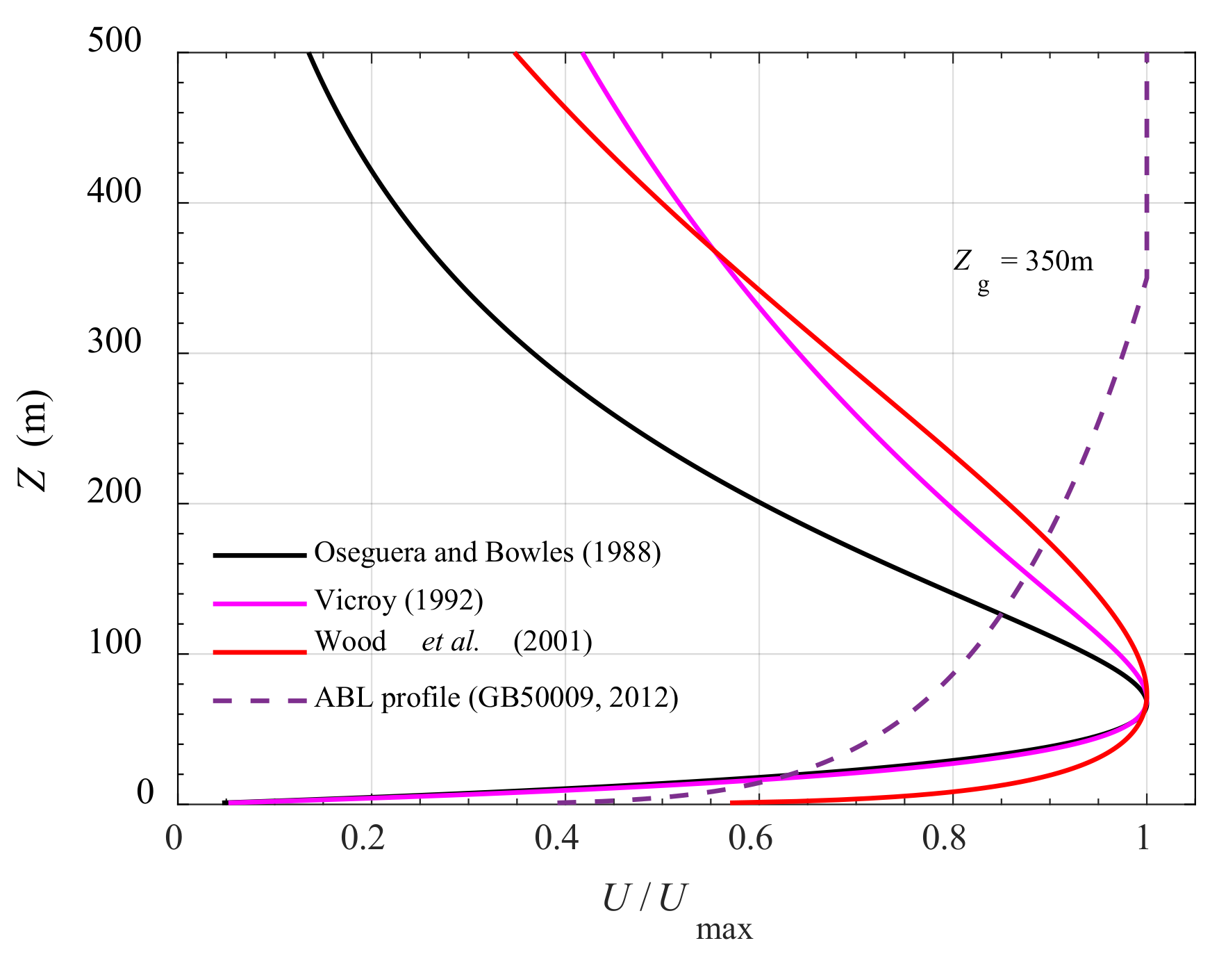
  13. Wood, G.S.; Kwok, K.C.; A Motteram, N.; Fletcher, D.F. Physical and Numerical Modelling of Thunderstorm Downbursts. J. Wind Eng. Ind. Aerodyn. 2001, 89, 535–552. [Google Scholar] [CrossRef]
  14. Holmes, J.D.; Oliver, S. An Empirical Model of a Downburst. Eng. Struct. 2000, 22, 1167–1172. [Google Scholar] [CrossRef]
  15. Savory, E.; Parke, G.A.; Zeinoddini, M.; Toy, N.; Disney, P. Modelling of Tornado and Microburst-Induced Wind Loading and Failure of a Lattice Transmission Tower. Eng. Struct. 2001, 23, 365–375. [Google Scholar] [CrossRef]
  16. Chen, L.; Letchford, C.W. A Deterministic–Stochastic Hybrid Model of Downbursts and its Impact on a Cantilevered Structure. Eng. Struct. 2004, 26, 619–629. [Google Scholar] [CrossRef]
  17. Wang, X.; Lou, W.; Li, H.N.; Chen, Y. Wind-Induced Dynamic Response of High-Rise Transmission Tower under Downburst Wind Load. J. Zhejiang Univ. 2009, 43, 1520–1525. (In Chinese) [Google Scholar]
  18. Wang, F.Y.; Xu, Y.L.; Qu, W.L. Multi-Scale Failure Analysis of Transmission Towers Under Downburst Loading. Int. J. Struct. Stab. Dyn. 2018, 18. [Google Scholar] [CrossRef]
  19. Sun, Q.; Wu, J.; Wang, D.; Xiang, Y.; Liu, H.; Sun, X. Analysis of the Quasi-Static Buffeting Responses of Transmission Lines to Moving Downburst. Comput. Model. Eng. Sci. 2020, 124, 287–302. [Google Scholar] [CrossRef]
  20. Kim, J.; Hangan, H. Numerical Simulations of Impinging Jets with Application to Downbursts. J. Wind Eng. Ind. Aerodyn. 2007, 95, 279–298. [Google Scholar] [CrossRef]
  21. Shehata, A.; El Damatty, A.; Savory, E. Finite Element Modeling of Transmission Line under Downburst Wind Loading. Finite Elements Anal. Des. 2005, 42, 71–89. [Google Scholar] [CrossRef]
  22. Shehata, A.; Nassef, A.; El Damatty, A. A Coupled Finite Element-Optimization Technique to Determine Critical Microburst Parameters for Transmission Towers. Finite Elem. Anal. Des. 2008, 45, 1–12. [Google Scholar] [CrossRef]
  23. Shehata, A.; El Damatty, A. Failure Analysis of a Transmission Tower during a Microburst. Wind Struct. Int. J. 2008, 11, 193–208. [Google Scholar] [CrossRef]
  24. Darwish, M.; El Damatty, A.A.; Hangan, H. Dynamic Characteristics of Transmission Line Conductors and Behaviour under Turbulent Downburst Loading. Wind Struct. Int. J. 2010, 13, 327–346. [Google Scholar] [CrossRef]
  25. Darwish, M.M.; El Damatty, A.A. Behavior of Self Supported Transmission Line Towers under Stationary Downburst Loading. Wind Struct. Int. J. 2011, 14, 481–498. [Google Scholar] [CrossRef]
  26. Ladubec, C.; El Damatty, A.A.; El Ansary, A.M. Effect of Geometric Nonlinear Behaviour of a Guyed Transmission Tower under Downburst Loading. Appl. Mech. Mater. 2012, 226–228, 1240–1249. [Google Scholar] [CrossRef]
  27. Aboshosha, H.; El Damatty, A. Effective Technique to Analyze Transmission Line Conductors under High Intensity Winds. Wind. Struct. 2014, 18, 235–252. [Google Scholar] [CrossRef]
  28. Elawady, A.; El Damatty, A. Longitudinal Force on Transmission Towers due to Non-Symmetric Downburst Conductor Loads. Eng. Struct. 2016, 127, 206–226. [Google Scholar] [CrossRef]
  29. Darwish, M.; El Damatty, A. Critical Parameters and Configurations Affecting the Analysis and Design of Guyed Transmission Towers under Downburst Loading. Pract. Period. Struct. Des. Constr. 2017, 22, 04016017. [Google Scholar] [CrossRef]
  30. Versteeg, H.; Malalasekera, W. An Introduction to Computational Fluid Dynamics; Prentice-Hall: Hoboken, NJ, USA, 2007. [Google Scholar]
  31. Lübcke, H.; Schmidt, S.; Rung, T.; Thiele, F. Comparison of LES and RANS in Bluff-Body Flows. J. Wind. Eng. Ind. Aerodyn. 2001, 89, 1471–1485. [Google Scholar] [CrossRef]
  32. Sengupta, A.; Sarkar, P.P. Experimental Measurement and Numerical Simulation of an Impinging Jet with Application to Thunderstorm Microburst Winds. J. Wind Eng. Ind. Aerodyn. 2008, 96, 345–365. [Google Scholar] [CrossRef]
  33. Yan, Z.; Zhong, Y.; Lin, W.E.; Savory, E.; You, Y. Evaluation of RANS and LES Turbulence Models for Simulating a Steady 2-D Plane Wall Jet. Eng. Comput. 2018, 35, 211–234. [Google Scholar] [CrossRef]
  34. Spalart, P.R. Detached-Eddy Simulation. Annu. Rev. Fluid Mech. 2009, 41, 181–202. [Google Scholar] [CrossRef]
  35. Abd-Elaal, E.S.; Mills., J.E.; Xing M, . Empirical models for predicting unsteady-state downburst wind speeds. J. Wind. Eng. Ind. Aerodyn. 2014, 129, 49–63. [Google Scholar] [CrossRef]
  36. Menter, F.R.; Egorov, Y. The Scale-Adaptive Simulation Method for Unsteady Turbulent Flow Predictions. Part 1: Theory and Model Description. Flow Turbul Combust. 2010, 85, 113–138. [Google Scholar] [CrossRef]
  37. Chen, L.; Letchford, C. Parametric Study on the Along-Wind Response of the CAARC Building to Downbursts in the Time Domain. J. Wind Eng. Ind. Aerodyn. 2004, 92, 703–724. [Google Scholar] [CrossRef]
  38. Chen, X. Analysis of Alongwind Tall Building Response to Transient Nonstationary Winds. J. Struct. Eng. 2008, 134, 782–791. [Google Scholar] [CrossRef] [Green Version]
  39. Huang, G.; Liao, H.; Li, M. New formulation of Cholesky Decomposition and Applications in Stochastic Simulation. Probabilistic Eng. Mech. 2013, 34, 40–47. [Google Scholar] [CrossRef]
  40. Su, Y.; Huang, G.; Xu, Y.-L. Derivation of Time-Varying Mean for Non-Stationary Downburst Winds. J. Wind Eng. Ind. Aerodyn. 2015, 141, 39–48. [Google Scholar] [CrossRef]
  41. Peng, L.; Huang, G.; Chen, X.; Yang, Q. Evolutionary Spectra-Based Time-Varying Coherence Function and Application in Structural Response Analysis to Downburst Winds. J. Struct. Eng. 2018, 144, 04018078. [Google Scholar] [CrossRef]
  42. Holmes, J.D. Recent Developments in the specification of wind loads on transmission lines. J. Wind. Eng. 2008, 5, 8–18. [Google Scholar]
  43. Letchford, C.; Mans, C.; Chay, M. Thunderstorms—their Importance in Wind Engineering (A Case for the Next Generation Wind Tunnel). J. Wind Eng. Ind. Aerodyn. 2002, 90, 1415–1433. [Google Scholar] [CrossRef]
  44. American Society of Civil Engineering. ASCE Manuals and Reports on Engineering Practice No.74; Wong, C.J., Miller, M.D., Eds.; American Society of Civil Engineering: Reston, VA, USA, 2020. [Google Scholar]
  45. AS/NZS 7000. Australia/New Zealand Standard Overhead Line Design—Detailed Procedures; AS/NZS 7000: Sydney, Australia, 2010. [Google Scholar]
  46. Choi, E.C.C. Proposal for unified terrain categories exposures and velocity profiles. In Proceedings of the Seventh Asia-Pacific Conference on Wind Engineering, Taipei, Taiwan, 8–12 November 2009. [Google Scholar]
  47. Holmes, J.D. Developments in codification of wind loads in the Asia Pacific. In Proceedings of the Seventh Asia-Pacific Conference on Wind Engineering, Taipei, Taiwan, 8–12 November 2009. [Google Scholar]
  48. ISO 4354 International Standard Wind Actions on Structures; International Organization for Standardization: Geneva, Switzerland, 2009.
  49. Mara, T.; Hong, H. Effect of Wind Direction on the Response and Capacity Surface of a Transmission Tower. Eng. Struct. 2013, 57, 493–501. [Google Scholar] [CrossRef]
  50. Yang, F.; Zhang, H. Two Case Studies on Structural Analysis of Transmission Towers under Downburst. Wind Struct. Int. J. 2016, 22, 685–701. [Google Scholar] [CrossRef]
  51. Zhao, Y.; Sun, Q.; Song, Z.; Wang, D.; W, X. A Dynamic Responses and Evaluation Method of the Downburst Wind Loads Effect on a Transmission Tower. J. Vib. Shock. 2021, 40, 179–188+195. (In Chinese) [Google Scholar]
  52. Chay, M.T.; Wilson, R.; Albermani, F. Gust Occurrence in Simulated Non-Stationary Winds. J. Wind. Eng. Ind. Aerodyn. 2008, 96, 2161–2172. [Google Scholar] [CrossRef]
  53. Hjelmfelt, M.R. Structure and Life Cycle of Microburst Outflows Observed in Colorado. J. Appl. Meteorol. 1988, 27, 900–927. [Google Scholar] [CrossRef]
  54. Zhang, S.; Yang, Q.; Solari, G.; Li, B.; Huang, G. Characteristics of Thunderstorm Outflows in Beijing Urban Area. J. Wind. Eng. Ind. Aerodyn. 2019, 195, 104011. [Google Scholar] [CrossRef]
  55. Xhelaj, A.; Burlando, M.; Solari, G. A General-Purpose Analytical Model for Reconstructing the Thunderstorm Outflows of Travelling Downbursts Immersed in ABL Flows. J. Wind. Eng. Ind. Aerodyn. 2020, 207, 104373. [Google Scholar] [CrossRef]
  56. Canepa, F.; Burlando, M.; Solari, G. Vertical Profile Characteristics of Thunderstorm Outflows. J. Wind. Eng. Ind. Aerodyn. 2020, 206, 104332. [Google Scholar] [CrossRef]
  57. Oseguera, R.M.; Bowles, R.L. A Simple, Analytic 3-Dimensional Downburst Model Based on Boundary Layer Stagnation Flow; NASA Technical Memorandum 100632; National Aeronautics and Space Administration: Hampton, VA, USA, 1988; p. 19. [Google Scholar]
  58. Vicroy, D.D. Assessment of Microburst Models for Downdraft Estimation. J. Aircr. 1992, 29, 1043–1048. [Google Scholar] [CrossRef]
  59. GB 50009–2012. Load Code for the Design of Building Structures; China Architecture and Building Press: Beijing, China, 2012. (In Chinese) [Google Scholar]
  60. Lin, W.; Savory, E. Large-Scale Quasi-Steady Modelling of a Downburst Outflow Using a Slot Jet. Wind Struct. Int. J. 2006, 9, 419–440. [Google Scholar] [CrossRef]
  61. George, W.K.; Abrahamsson, H.; Eriksson, J.; Karlsson, R.I.; Löfdahl, L.; Wosnik, M. A Similarity Theory for the Turbulent Plane Wall Jet without External Stream. J. Fluid Mech. 2000, 425, 367–411. [Google Scholar] [CrossRef]
  62. Chay, M.T.; Albermani, F.; Wilson, R. Numerical and Analytical Simulation of Downburst Wind Loads. Eng. Struct. 2006, 28, 240–254. [Google Scholar] [CrossRef] [Green Version]
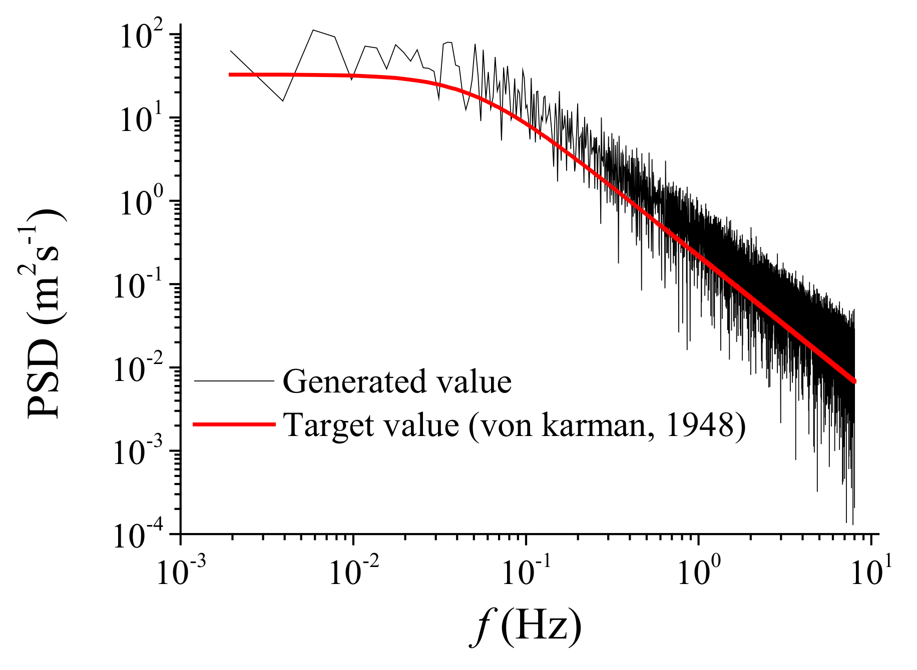
  63. Von Karman, T. Progress in the Statistical Theory of Turbulence. Proc. Natl. Acad. Sci. USA 1948, 34, 530–539. [Google Scholar] [CrossRef] [PubMed] [Green Version]
  64. Shinozuka, M.; Deodatis, G. Simulation of Stochastic Processes by Spectral Representation. Appl. Mech. Rev. 1991, 44, 191–204. [Google Scholar] [CrossRef]
  65. Holmes, J.D. Wind Loading of Structures, 3rd ed.; CRC Press: Boca Raton, FL, USA, 2015. [Google Scholar]
  66. Crandall, S.H.; Mark, W.D. Random Vibration in Mechanical Systems; Academic Press: New York, NY, USA, 1963. [Google Scholar]
  67. ANSYS, Inc. ANSYS Mechanical APDL Element Reference; ANSYS, Inc.: Canonsburg, PA, USA, 2018. [Google Scholar]
  68. Loredo-Souza, A.; Davenport, A. The Influence of the Design Methodology in the Response of Transmission Towers to Wind Loading. J. Wind Eng. Ind. Aerodyn. 2003, 91, 995–1005. [Google Scholar] [CrossRef]
  69. Holmes, J. Along-Wind Response of Lattice Towers: Part I-Derivation of Expressions for Gust Response Factors. Eng. Struct. 1994, 16, 287–292. [Google Scholar] [CrossRef]
  70. Holmes, J.D. Along-Wind Response of Lattice Towers—II. Aerodynamic Damping and Deflections. Eng. Struct. 1996, 18, 483–488. [Google Scholar] [CrossRef]
  71. Lin, J.; Zhang, Y.; Li, Q.; Williams, F. Seismic Spatial Effects for Long-Span Bridges, Using the Pseudo Excitation Method. Eng. Struct. 2004, 26, 1207–1216. [Google Scholar] [CrossRef]
  72. Lin, W.; Savory, E.; McIntyre, R.; Vandelaar, C.; King, J. The Response of an Overhead Electrical Power Transmission Line to Two Types of Wind Forcing. J. Wind Eng. Ind. Aerodyn. 2012, 100, 58–69. [Google Scholar] [CrossRef]
  73. Elawady, A.; Aboshosha, H.; El Damatty, A.; Bitsuamlak, G.; Hangan, H.; Elatar, A. Aero-Elastic Testing of Multi-Spanned Transmission Line Subjected to Downbursts. J. Wind Eng. Ind. Aerodyn. 2017, 169, 194–216. [Google Scholar] [CrossRef]
  74. Li, Y.; Li, Z.; Savory, E.; Zhong, Y.; Yan, Z. Wind Tunnel Measurement of Overall and Sectional Drag Coefficients for a Super High-Rise Steel Tube Transmission Tower. J. Wind Eng. Ind. Aerodyn. 2020, 206, 104363. [Google Scholar] [CrossRef]
  75. Zhao, S.; Yan, Z.; Savory, E. Design Wind Loads for Transmission Towers with Cantilever Cross-Arms Based on the Inertial Load Method. J. Wind Eng. Ind. Aerodyn. 2020, 205, 104286. [Google Scholar] [CrossRef]
  76. National Research Council of Canada. National Building Code of Canada; National Research Council of Canada: Ottawa, ON, Canada, 2015.
  77. Chen, X. Analysis of Multimode Coupled Buffeting Response of Long-Span Bridges to Nonstationary Winds with Force Parameters from Stationary Wind. J. Struct. Eng. 2015, 141, 04014131. [Google Scholar] [CrossRef]
  78. DL/T 5154–2012. Technical Code for the Design of Tower and Pole Structures of Overhead Transmission Lines; China Planning Press: Beijing, China, 2012. (In Chinese) [Google Scholar]
Figure 1. Comparison among three vertical profile models and conventional ABL profile.
Buildings 12 00148 g001
Figure 2. Time functions of the time-varying mean wind speeds, (a) Case 1. (b) Case 2.
Buildings 12 00148 g002
Figure 3. EPSD estimation of time modulation functions. (a) Modulation function 1. (b) Modulation function 2.
Buildings 12 00148 g003
Figure 4. Simulated downburst wind speed time history.
Buildings 12 00148 g004
Figure 5. PSD of generation versus corresponding targets for stationary components κ (z, t).
Buildings 12 00148 g005
Figure 6. Details of transmission towers.
Buildings 12 00148 g006
Figure 7. FEM diagram of transmission tower A: (a) isometric view, (b) plan views, (c) first mode, (d) second mode, (e) third mode.
Buildings 12 00148 g007
Figure 8. Mean and RMS responses of the tower tip displacement. (a) Case 1. (b) Case 2.
Buildings 12 00148 g008
Figure 9. Time history of tip displacement.
Buildings 12 00148 g009
Figure 10. Time history of background and resonant components.
Buildings 12 00148 g010
Figure 11. Comparison of predicted RMS response from time domain and frequency domain analysis.
Buildings 12 00148 g011
Figure 12. The influence of different parameters on DAF, (a) effect of half-height of downburst and structural frequency, (b) effect of half-height of downburst and damping ratio.
Buildings 12 00148 g012
Figure 13. Comparison of DAF and GLF.
Buildings 12 00148 g013
Figure 14. Comparison of axial forces from ESWL, FEM and ASCE guidelines.
Buildings 12 00148 g014
Table 1. Parameters for the vertical profile models in Figure 1.
Parametersr (m)R (m)z* (m)ε (m)λ (1/s)Zmax (m)δ (m)α
Oseguera and Bowles [57]11211000200300.41465 *--
Vicroy [58]-----67--
Wood [13]------400-
Power law of ABL [59]-------0.16
* These values are calculated from other independent parameters. - There is no value in the corresponding model.
Table 2. First three natural frequencies of selected towers (unit: Hz).
1st-Order2nd-Order3rd-Order
Tower A1.2571.2891.927
Tower B1.4301.4841.915
Tower C1.7271.8382.006
Table 3. Approximate dynamic properties from codes.
Type of StructureFundamental Frequency, f1 (Hz)Damping Ratio, ξs
Latticed Tower [44]2.0–4.00.04
H-Frame [44]1.0–2.00.02
Pole [44]0.5–1.00.02
Steel structure [59](0.007–0.013) H0.01
Publisher’s Note: MDPI stays neutral with regard to jurisdictional claims in published maps and institutional affiliations.

