
Potential Application of BIM in RFI in Building Projects


 , ,
, ,  and
and
Abstract
:1. Introduction
2. Materials and Methods
2.1. Stage 1: Contextualization of RFIs in the AECO Industry
2.2. Stage 2: RFI Case Applied to 17 Projects
2.3. Stage 3: RFI from a BIM Perspective
3. Background
3.1. Performance Indicators
3.2. RFI Issuance Process
3.3. RFI from a BIM Perspective
4. Results and Discussion
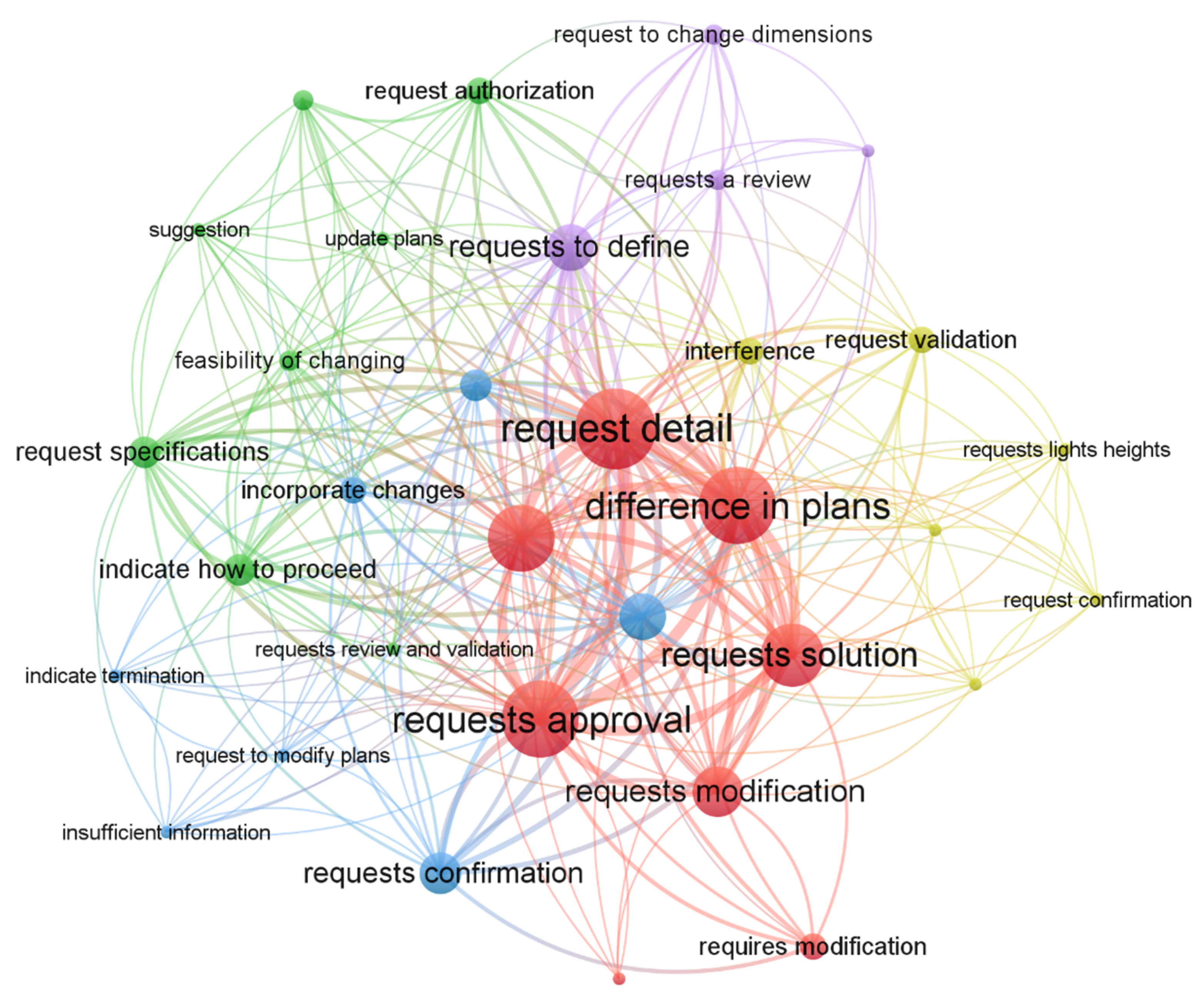
4.1. RFI Classification Methodology
4.2. RFI Issuance and Response Process
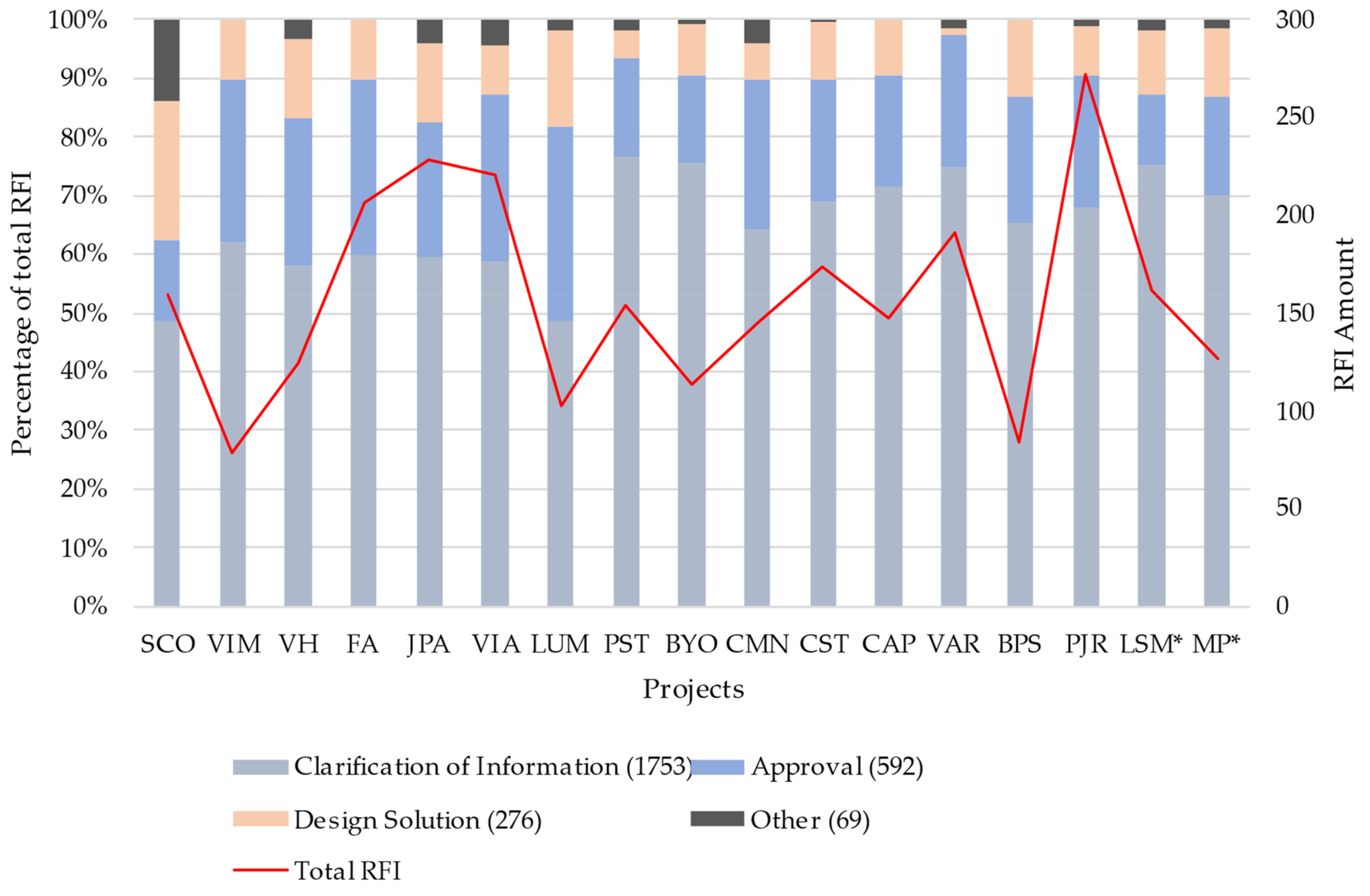
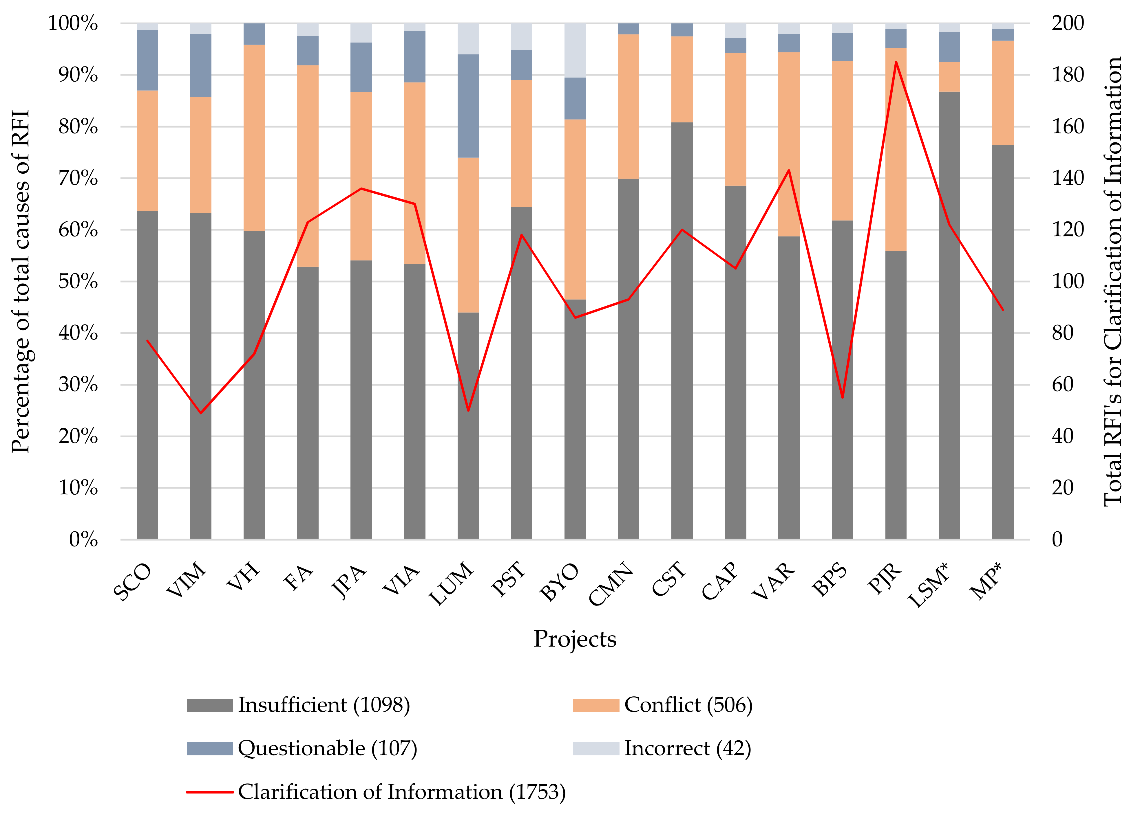
4.3. Analysis of RFIs Associated with Building Projects
4.4. Reactive or Preventive BIM Uses
4.5. Analysis of the Potential Benefit of BIM Uses for the Mitigation of RFI
5. Discussion
6. Conclusions
Author Contributions
Funding
Institutional Review Board Statement
Informed Consent Statement
Data Availability Statement
Acknowledgments
Conflicts of Interest
References
- Saldías, R. Estimación de los Beneficios de Realizar una Coordinación Digital de Proyectos con Tecnologías BIM; Universidad de Chile: Santiago, Chile, 2010. [Google Scholar]
- PlanBIM. Estándar BIM para Proyectos Públicos; Planbim Corfo: Santiago, Chile, 2019. [Google Scholar]
- Monteiro, A.; Poças Martins, J. BIM Modeling for Contractors—Improving; CIV W078: Beirut, Lebanon, 2012; pp. 17–19. [Google Scholar]
- BIMnD. Mediciones y Presupuestos del Edificio Virtual Desarrollado en BIM; BIMnD: Granada, Spain, 2018. [Google Scholar]
- Sawhney, A.; Riley, M.; Irizarry, J. Construction 4.0: An Innovation Platform for the Built Environment, 2020th ed.; Sawhney, A., Riley, M., Irizarry, J., Eds.; Routledge: New York, NY, USA, 2020; Volume 53, ISBN 9788578110796. [Google Scholar]
- Madera21. BIM: La Metodología que da mas Eficiencia a las Construcciones; Madera21: Santiago, Chile, 2017. [Google Scholar]
- Araya, F. State of the art of the use of BIM for resolution of claims in construction projects. Rev. Ing. Constr. 2019, 34, 299–306. [Google Scholar] [CrossRef] [Green Version]
- Latorre Uriz, A.; Sanz, C.; Sánchez, B. Aplicación de un modelo Lean-BIM para la mejora de la productividad en redacción de proyectos de edificación. Inf. Constr. 2019, 71, e313. [Google Scholar] [CrossRef] [Green Version]
- PMG. Business Improvement Proyecto Diagnóstico de Formación de Capital Humano en BIM; PMG: Santiago, Chile, 2018; p. 139. [Google Scholar]
- Radujković, M.; Vukomanović, M.; Dunović, I.B. Application of key performance indicators in South—Eastern European Construction. J. Civ. Eng. Manag. 2011, 3730, 521–530. [Google Scholar] [CrossRef]
- Herrera, R.F.; Mourgues, C.; Alarcon, L.F.; Pellicer, E. Assessing Design Process Performance of Construction Projects. In Proceedings of the CIB World Building Congress 2019, Hong Kong, China, 17–21 June 2019; pp. 1–10. [Google Scholar]
- Anumba, C.J.; Baugh, C.; Khalfan, M. Organisational structures to support concurrent engineering in construction. Ind. Manag. Data Syst. 2002, 102, 260–270. [Google Scholar] [CrossRef]
- Hanna, A.S.; Tadt, E.J.; Whited, G.C. Request for Information: Benchmarks and Metrics for Major Highway Projects. J. Civ. Eng. Manag. 2012, 138, 1347–1352. [Google Scholar] [CrossRef]
- Tilley, P.A.; Wyatt, A.; Mohamed, S. Indicators of Design and Documentation Deficiency. In Proceedings of the IGLC-5, Fifth Annual Conference of the International Group for Lean Construction, Gold Coast, Australia, 16–17 July 1997; pp. 137–148. [Google Scholar]
- Love, P.E.D.; Zhou, J.; Sing, C.; Kim, J. Assessing the impact of RFIs in electrical and instrumentation. J. Enfineering Des. 2014, 25, 177–193. [Google Scholar]
- Mohamed, S.; Tilley, P.A.; Tucker, S. Quantifying the Time and Costo Associated with the Request for Infomation (RFI) Process in Construction. Int. J. Constr. Inf. Technol. 1999, 7, 35–50. [Google Scholar]
- Shim, E.; Carter, B.; Kim, S. Request for Information (RFI) Management: A Case Study. In Proceedings of the 52nd ASC Annual International Conference Proceedings, Provo, UT, USA, 13–16 April 2016. [Google Scholar]
- Dinsmore, R.C. Investigating the Impact of the Request for Information Process in Construction. Bachelor’s Thesis, University of Southern Queensland, Queensland, Australia, 2013. [Google Scholar]
- Project Management Institute (PMI). A Guide to the Project Management Body of Knowledge PMBOK GUIDE, 6th ed.; PMI: Newtown Square, PA, USA, 2017; ISBN 9781628253825. [Google Scholar]
- Wilkins, C.; Kiviniemi, A. Engineering-centric BIM. ASHRAE J. 2008, 50, 44–48. [Google Scholar]
- Kreider, R.G.; Messner, J.I. The Uses of BIM: Classifying and Selecting BIM Uses; Penn State University: State College, PA, USA, 2013. [Google Scholar]
- Arayici, Y. Towards building information modelling for existing structures. Struct. Surv. 2008, 26, 210–222. [Google Scholar] [CrossRef] [Green Version]
- Lee, Y.S.; Kim, J.J. A Cost-Based Interior Design Decision Support System for Large-Scale Housing Projects. IntechOpen 2010, 2, 64. [Google Scholar] [CrossRef] [Green Version]
- Jongeling, R.; Kim, J.; Fischer, M.; Mourgues, C.; Olofsson, T. Automation in Construction Quantitative analysis of work flow, temporary structure usage, and productivity using 4D models. Autom. Constr. 2008, 17, 780–791. [Google Scholar] [CrossRef]
- Khanzode, A.; Fischer, M.; Reed, D. Benefits and Lessons Learned of Implementing Building Virtual Design and Construction (VDC) Technologies for Coordination of Mechanical, Electrical and Plumbings (MEP) Systems on a Large Healthcare Project. J. Inf. Technol. Constr. 2008, 13, 324–342. [Google Scholar]
- Tardif, M.; BIM: Reaching Forward, Reaching Back. AIArchitect This Week. 2008. Available online: https://info.aia.org/aiarchitect/thisweek08/0321/0321rc_face.htm (accessed on 31 December 2021).
- Majumdar, T.; Fischer, M.A.; Schwegler, B.R. Conceptual Design Review with a Virtual Reality Mock-Up Model. In Proceedings of the Joint International Conference on Computing and Decision Making in Civil and Building Engineering, Montréal, QC, Canada, 14–16 June 2006; pp. 2902–2911. [Google Scholar]
- Chau, K.W.; Anson, M.; Zhang, J.P. Four-Dimensional Visualization of Construction Scheduling and Site Utilization. J. Constr. Eng. Manag. 2004, 130, 598–606. [Google Scholar] [CrossRef] [Green Version]
- TEKLA International. TEKLA Corporation and Trimble to Improve Construction Field Layout Using Building Information Modeling; Trimble: Sunnyvale, CA, USA, 2008. [Google Scholar]
- Woo, J.; Wilsmann, J.; Kang, D. Use of As-Built Building Information Modeling; ASCE: Banff, AB, Canada, 2010; ISBN 978-0-7844-1109-4. [Google Scholar]
- Campbell, D.A. Building information modeling: The Web3D application for AEC. In Proceedings of the Twelfth International Conference on 3D Web Technology, Perugia, Italy, 15–18 April 2007; pp. 173–176. [Google Scholar]
- Freire, J.; Alarcón, L.F. Achieving Lean Design Process: Improvement Methodology. J. Constr. Eng. Manag. 2002, 128, 248–256. [Google Scholar] [CrossRef] [Green Version]
- Messner, J.; Anumba, C.; Dubler, C.; Goodman, S.; Kasprzak, C.; Kreider, R.; Leicht, R.; Saluja, C.; Zikic, N. BIM Project Execution Planning Guide—Version 2.2. Build. Alliance 2011, 1–135. [Google Scholar] [CrossRef]
- Zhiliang, M.; Zhenhua, W.; Wu, S.; Zhe, L. Application and extension of the IFC standard in construction cost estimating for tendering in China. Autom. Constr. 2011, 20, 196–204. [Google Scholar] [CrossRef]
- Kassem, M.; Brogden, T.; Dawood, N. BIM and 4D planning: A holistic study of the barriers and drivers to widespread adoption. J. Constr. Eng. Proj. Manag. 2012, 2, 1–10. [Google Scholar] [CrossRef] [Green Version]
- Barnes, P.; Davies, N. BIM in Principle and in Practice, 2nd ed.; ICE Publishing: London, UK, 2015. [Google Scholar]
- Gledson, B.J.; Greenwood, D.J. Surveying the extent and use of 4D BIM in the UK. J. Inf. Technol. Constr. ITcon 2016, 21, 57–71. [Google Scholar]
- Nisa Lau, S.E.; Zakaria, R.; Aminudin, E.; Saar, C.C.; Yusof, A.; Hafifi Che Wahid, C.M.F. A Review of Application Building Information Modeling (BIM) during Pre-Construction Stage: Retrospective and Future Directions. IOP Conf. Ser. Earth Environ. Sci. 2018, 143, 012050. [Google Scholar] [CrossRef]
- Oh, M.; Lee, J.; Hong, S.W.; Jeong, Y. Integrated system for BIM-based collaborative design. Autom. Constr. 2015, 58, 196–206. [Google Scholar] [CrossRef]
- Jung, N.; Lee, G. Automated classification of building information modeling (BIM) case studies by BIM use based on natural language processing (NLP) and unsupervised learning. Adv. Eng. Inform. 2019, 41, 100917. [Google Scholar] [CrossRef]
- Alwisy, A.; Al-Husseing, M.; Al-Jibouri, S.H. BIM Approach for Automated Drafting and Design for Modular Construction Manufacturing. In Proceedings of the International Conference on Computing in Civil Engineering, Clearwater Beach, FL, USA, 17–20 June 2012. [Google Scholar]
- Kubicki, S.; Guerriero, A.; Schwartz, L.; Daher, E.; Idris, B. Assessment of synchronous interactive devices for BIM project coordination: Prospective ergonomics approach. Autom. Constr. 2019, 101, 160–178. [Google Scholar] [CrossRef]
- Hergunsel, M.F. Benefits of Building Information Modeling for Construction Managers and BIM Based Scheduling. Master’s Thesis, Worcester Polytechnic Institute, Worcester, MA, USA, 2011. [Google Scholar]
- Kelly, D.; Ilozor, B. Performance outcome assessment of the integrated project delivery (IPD) method for commercial construction projects in USA. Int. J. Constr. Manag. 2020, 1–9. [Google Scholar] [CrossRef]
- Das, M.; Tao, X.; Liu, Y.; Cheng, J.C.P. A blockchain-based integrated document management framework for construction applications. Autom. Constr. 2022, 133, 104001. [Google Scholar] [CrossRef]
- Vahabi, A.; Nasirzadeh, F.; Mills, A. Impact of project briefing clarity on construction project performance. Int. J. Constr. Manag. 2020, 1–13. [Google Scholar] [CrossRef]
- Kim, J.J.; Petrov, A.L.; Lim, J.; Kim, S. Comparing Cost Performance of Project Delivery Methods Using Quantifiable RFIs: Cases in California Heavy Civil Construction Projects. Int. J. Civ. Eng. 2021, 1–13. [Google Scholar] [CrossRef]


| ID | Company Size | Construction Type | Number of Levels | Number of Subways | Constructed Meters (m2) |
|---|---|---|---|---|---|
| SCO | Large | Hotel | 36 | 4 | 31,000 |
| VIM | Large | Habitational | 14 | 2 | 22,630 |
| VH | Large | Habitational | 15 | 1 | 17,434 |
| FA | Large | Habitational | 11 | 2 | 16,681 |
| JPA | Large | Habitational | 6 | 2 | 13,550 |
| VIA | Large | Habitational | 24 | 2 | 21,352 |
| LUM | Large | Habitational | 5 | 2 | 9904 |
| PST | Large | Habitational | 10 | 3 | 9100 |
| BYO | Large | Habitational | 3 | 4 | 10,010 |
| CMN | Large | Habitational | 16 | 1 | 13,215 |
| CST | Large | Habitational | 15 | 2 | 12,500 |
| CAP | Large | Shopping Mall | 8 | 3 | 31,790 |
| VAR | Medium | Habitational | 20 | 2 | 19,939 |
| BPS | Medium | Habitational | 24 | 2 | 36,000 |
| PJR | Large | Habitational | 5 | 3 | 11,000 |
| LSM | Large | Habitational | 20 | 2 | 11,842 |
| MP | Large | Habitational | 18 | 2 | 20,187 |
| Indicator | Description |
|---|---|
| Cost of designers (CD) | Sum of the hours spent by each professional on the project multiplied by the hourly cost of each designer. |
| Reworking (RW) | Percentage of hours the design team spends working on a task that has already been performed (rework) as a proportion of the total time spent working on the project during that week. |
| Latency (LA) | Average waiting time between request for and delivery of information between two or more project members. |
| Quality defects (QD) | Number of failures, errors, or nonconformities detected in the design process per week. |
| Achieving commitment (AC) | Percentage of the plan completed during the week. |
| List deviation (SD) | The ratio between the actual number of days and the expected number of days in the design stage. |
| Cost deviation (CD) | The ratio of the actual cost to the expected cost of the design stage. |
| Request for information (RFI) | The number of requests for information at the end of the design stage, before construction begins. |
| Indicator | Description |
|---|---|
| Change requirements (CR) | Number of change requirements at the construction stage. |
| Cost of changes (CC) | Costs associated with changes required at the construction stage (design cost + construction cost). |
| Request for information (RFI) | The number of post-design information requests during construction. Includes interference problems. |
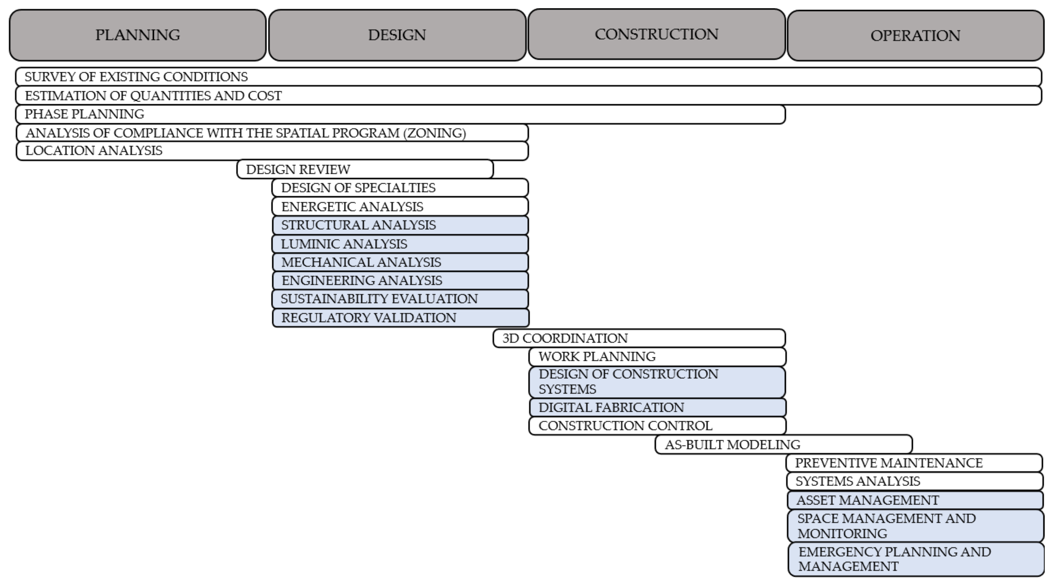
| Primary BIM Use | Definition | Scope, Application and Potential Uses |
|---|---|---|
| Existing conditions survey | Process of developing one or more BIM models to consider the current conditions of a site and/or its facilities and/or a specific area within a building or infrastructure. |
|
| Quantity and cost estimating | Process of using information to extract quantities of project components and materials at different stages of the project. Allows for efficient cost management. |
|
| Phase planning | Process of using one or more 4D models to plan the construction sequence of a project and/or occupancy stages. Four-dimensional modeling is a powerful visualization and communication tool that can give the project team, including the client, a better understanding of project milestones and construction plans. |
|
| 3D coordination: | Planning process between the different disciplines prior to design to avoid potential interferences, including the detection of interference once the disciplines’ designs are generated. |
|
| Spatial program compliance analysis | Process of evaluating whether the design efficiently and accurately meets the areas included in the project requirements, considering established regulations and standards. |
|
| Location analysis | Process of using one or more BIM and/or GIS models to evaluate the properties of an area and determine the best location and orientation of a future project. |
|
| Specialty design | Process of creating BIM models of the various disciplines involved in a project. It is also considered a prerequisite for design review. |
|
| Design review | Process of reviewing possible responses to project requirements in different areas through the creation of BIM models that may contain multiple design alternatives. It includes aspects such as evaluation of program compliance and preview of space aesthetics and layout in a virtual environment. |
|
| Engineering analysis | Process involving the most relevant traditional engineering methods based on design specifications, including structural analysis; lighting analysis; energy, mechanical and sanitary analyses, etc. [21]. |
|
| Site planning | Process in which the activities related to the existing, temporary, and proposed elements of a project are planned graphically during construction. |
|
| Construction control | Process of monitoring, analyzing, managing and optimizing construction through one or more BIM models. |
|
| As-built modeling | Modeling process in which the physical conditions of all elements that are part of a building or infrastructure are accurately represented. The model of record must, at a minimum, contain information relating to the main architectural, structural, and MEP elements. It is the culmination of all BIM modeling throughout the project. |
|
| Systems analysis | Process in which the performance analysis of a building or infrastructure is performed according to the original design approach of the specialties. |
|
| Preventive maintenance | Process in which the functional maintenance of the structure of a building or infrastructure and its equipment is developed during its operation. |
|
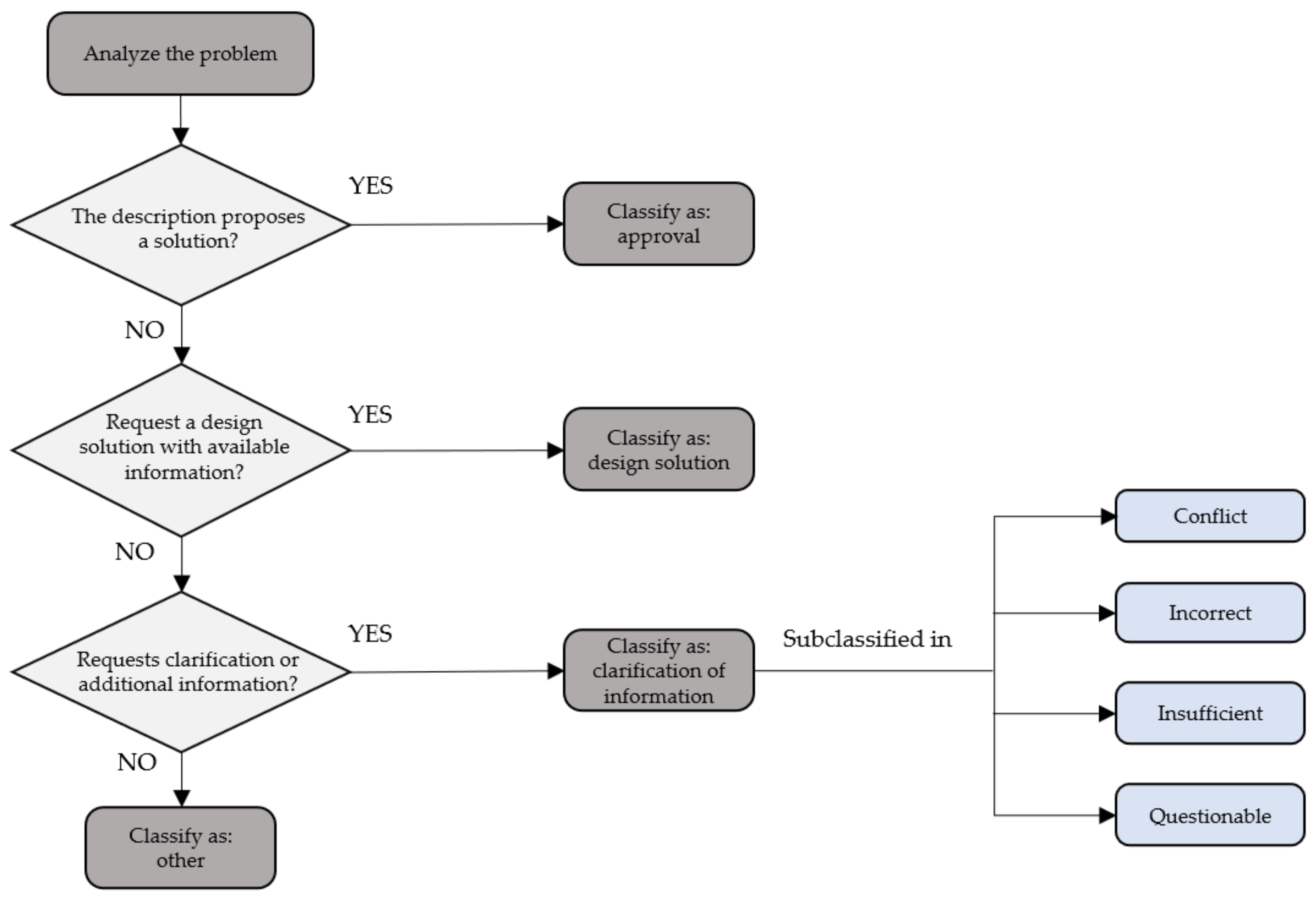
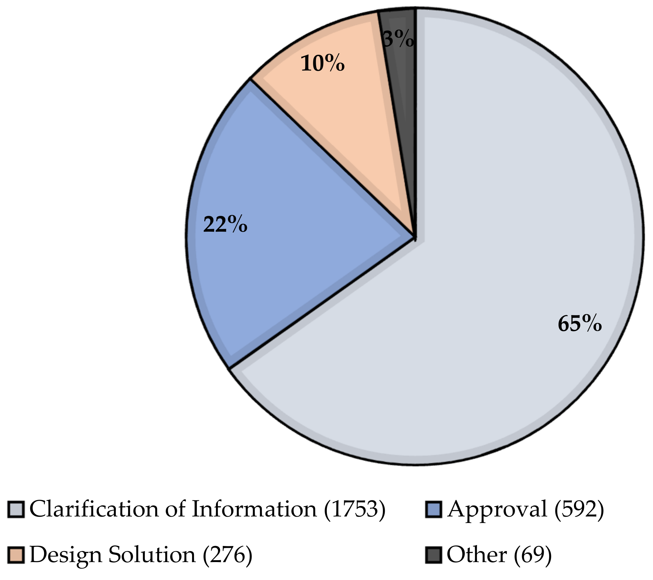
| Type of RFI | Description |
|---|---|
| Alternative design solutions | Requests for an alternative design solution from the design team/manager based on the information available. |
| Approvals | Drawings, documents, material samples, or technical samples of information submitted to the design team/manager for approval. |
| Clarifications of information | Requests for additional information or clarification of information from the design team/manager. |
| Other | Issued for any other reason. |
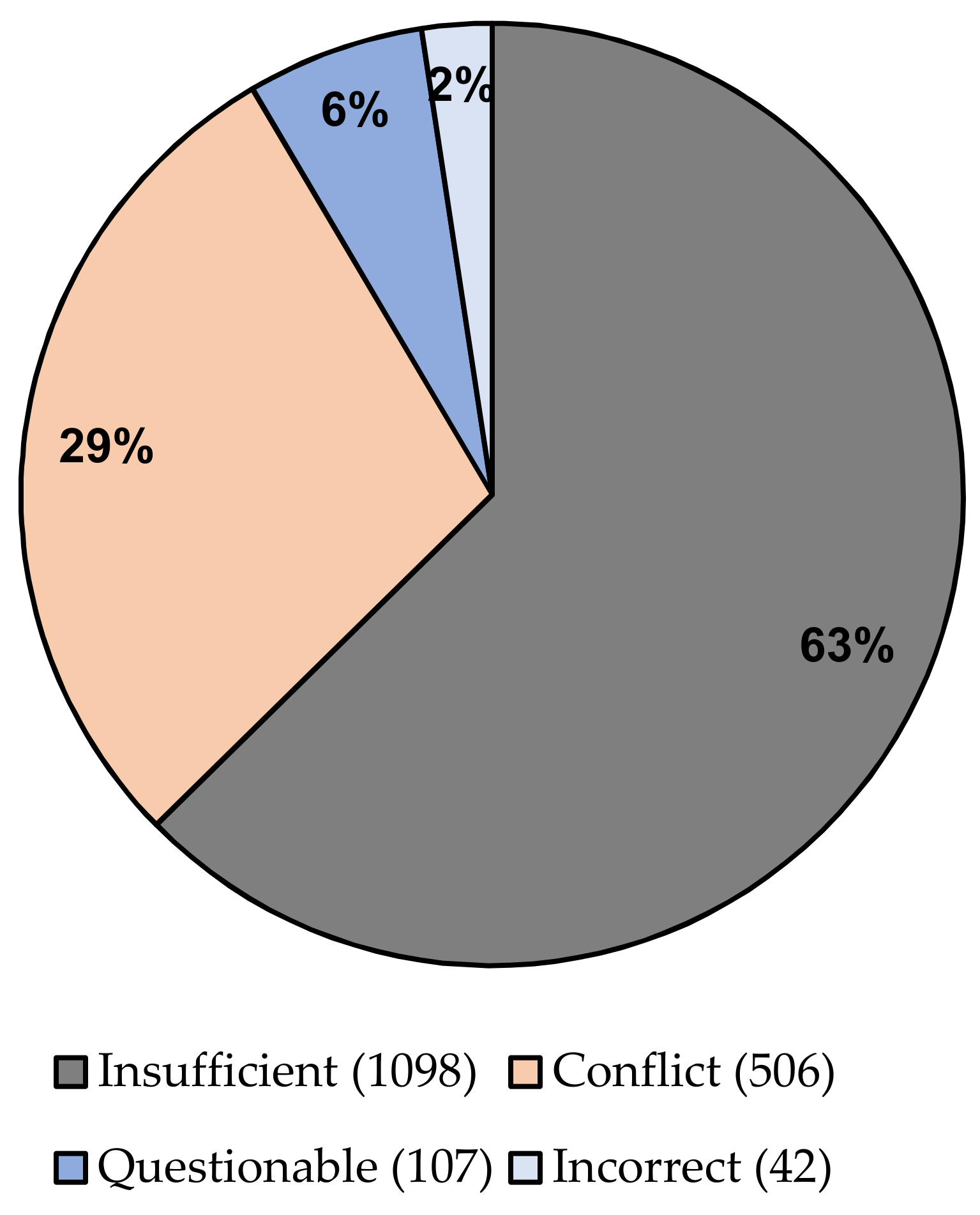
| Cause of RFI | Description of the Cause |
|---|---|
| Conflict | Issuance of RFI when two or more contract documents provide contradictory information on the same element or item. |
| Incorrect | Issuance of RFI when the contract documents provide erroneous information. |
| Insufficient | Issuance of RFI when the information provided in the contract document is considered incomplete. |
| Questionable | Issuance of RFI when the information provided in the contract documents is considered inappropriate in relation to its application in the project, although construction can still be carried out as designed. |
| Situation | Type of RFI | Cause |
|---|---|---|
| “Please clarify at every how many m2 the soil density should be taken in compacted fills”. | Clarification of information | Insufficient information |
| “It is suggested to install a double angle 30 × 30 × 3, in horizontal joints of OSB sheets, since there is no detail. This will prevent buckling and provide better fastening. If approved, a cost increase will be evaluated”. | Approval | Submits information and proposal for evaluation and subsequent validation. |
| “In axis 11/B the cable named S3-1077 cannot be tensioned due to the presence of the pillar present in 11/B. Please provide a tensioning solution for this level and the levels above”. | Alternative design solution | It is not possible to carry out the action as planned, so another alternative is requested in order to be able to execute it. |
| “The formalization of materialization of provisional boundary closing with definitive character has been made by means of plates of height 2.00 mts plus straight passing post with three strands of barbed wire, without cost for the real estate, once the work is finished the closings will be delivered in good condition corresponding to lot 3A between the vertices Z2 to Z3”. | Other | This type of RFI is used for information rather than to express a query, so it is not possible to include it in the above-mentioned categories. |
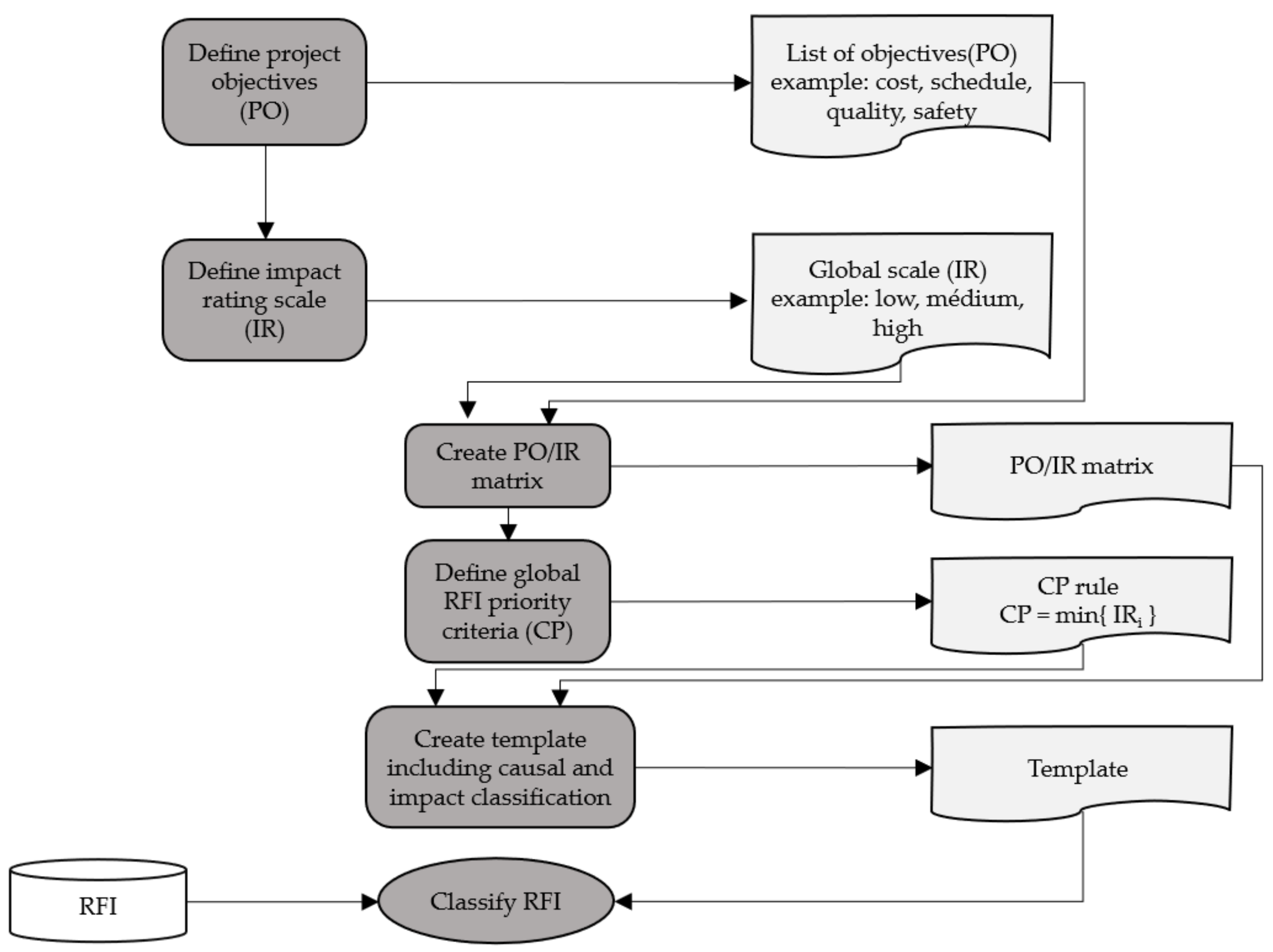
| Objectives | Very Low (0.05) | Low (0.10) | Moderate (0.20) | High (0.40) | Very High (0.80) |
|---|---|---|---|---|---|
| Cost | Negligible increase in costs | Cost increase <10% | 10–20% cost increase | 20–40% cost increase | Cost increase >40%. |
| Time | Negligible time increase | Time increase <5%. | 5–10% increase in time | 10–20% increase in time | Time increase >20%. |
| Scope | Decrease in range barely noticeable | Secondary scope areas affected | Major scope areas affected | Reduction in scope unacceptable to the client | The final element of the project is effectively unusable |
| Quality | Decrease in quality hardly noticeable | Only very demanding applications are affected | Reduction in quality requires client approval | Reduction in quality unacceptable to the client | The final element of the project is effectively unusable |
| BIM Uses | Preventive | Reactive |
|---|---|---|
| Survey of existing conditions | ✓ | ✓ |
| Estimation of quantities and costs | ✓ | |
| Phase planning | ✓ | |
| Special program compliance analysis | ✓ | |
| Location analysis | ✓ | |
| 3D Coordination | ✓ | ✓ |
| Specialty design | ✓ | |
| Design review | ✓ | ✓ |
| Engineering analysis | ✓ | ✓ |
| Site planning | ✓ | ✓ |
| Construction control | ✓ | |
| As-built modeling | ✓ |
| BIM Uses | Approval | Alternative Design Solution | Clarification of Information | Others |
|---|---|---|---|---|
| Survey of existing conditions | 0 | 0 | 0 | 0 |
| Estimation of quantities and costs | 0 | 1 | 30 | 0 |
| Phase planning | 0 | 1 | 8 | 3 |
| Special program compliance analysis | 0 | 2 | 0 | 0 |
| Location analysis | 0 | 5 | 0 | 0 |
| 3D Coordination | 0 | 49 | 385 | 4 |
| Specialty design | 9 | 135 | 935 | 21 |
| Design review | 2 | 2 | 15 | 1 |
| Engineering analysis | 1 | 21 | 8 | 5 |
| Site planning | 0 | 3 | 4 | 3 |
| Construction control | 0 | 1 | 0 | 0 |
| As-built modeling | 0 | 0 | 2 | 0 |
| BIM Uses | Approval | Alternative Design Solution | Clarification of Information | Others |
|---|---|---|---|---|
| Survey of existing conditions | 0 | 0 | 0 | 0 |
| Estimation of quantities and costs | 0 | 0 | 1 | 1 |
| Phase planning | 0 | 0 | 1 | 0 |
| Special program compliance analysis | 0 | 0 | 0 | 0 |
| Location analysis | 0 | 0 | 0 | 0 |
| 3D Coordination | 1 | 0 | 3 | 1 |
| Specialty design | 2 | 3 | 37 | 14 |
| Design review | 565 | 232 | 1679 | 44 |
| Engineering analysis | 23 | 41 | 31 | 6 |
| Site planning | 1 | 0 | 0 | 2 |
| Construction control | 0 | 0 | 1 | 1 |
| As-built modeling | 0 | 0 | 0 | 0 |
Publisher’s Note: MDPI stays neutral with regard to jurisdictional claims in published maps and institutional affiliations. |
© 2022 by the authors. Licensee MDPI, Basel, Switzerland. This article is an open access article distributed under the terms and conditions of the Creative Commons Attribution (CC BY) license (https://creativecommons.org/licenses/by/4.0/).
Share and Cite
Morales, F.; Herrera, R.F.; Rivera, F.M.-L.; Atencio, E.; Nuñez, M. Potential Application of BIM in RFI in Building Projects. Buildings 2022, 12, 145. https://doi.org/10.3390/buildings12020145
Morales F, Herrera RF, Rivera FM-L, Atencio E, Nuñez M. Potential Application of BIM in RFI in Building Projects. Buildings. 2022; 12(2):145. https://doi.org/10.3390/buildings12020145
Chicago/Turabian StyleMorales, Francisca, Rodrigo F. Herrera, Felipe Muñoz-La Rivera, Edison Atencio, and Manuel Nuñez. 2022. "Potential Application of BIM in RFI in Building Projects" Buildings 12, no. 2: 145. https://doi.org/10.3390/buildings12020145