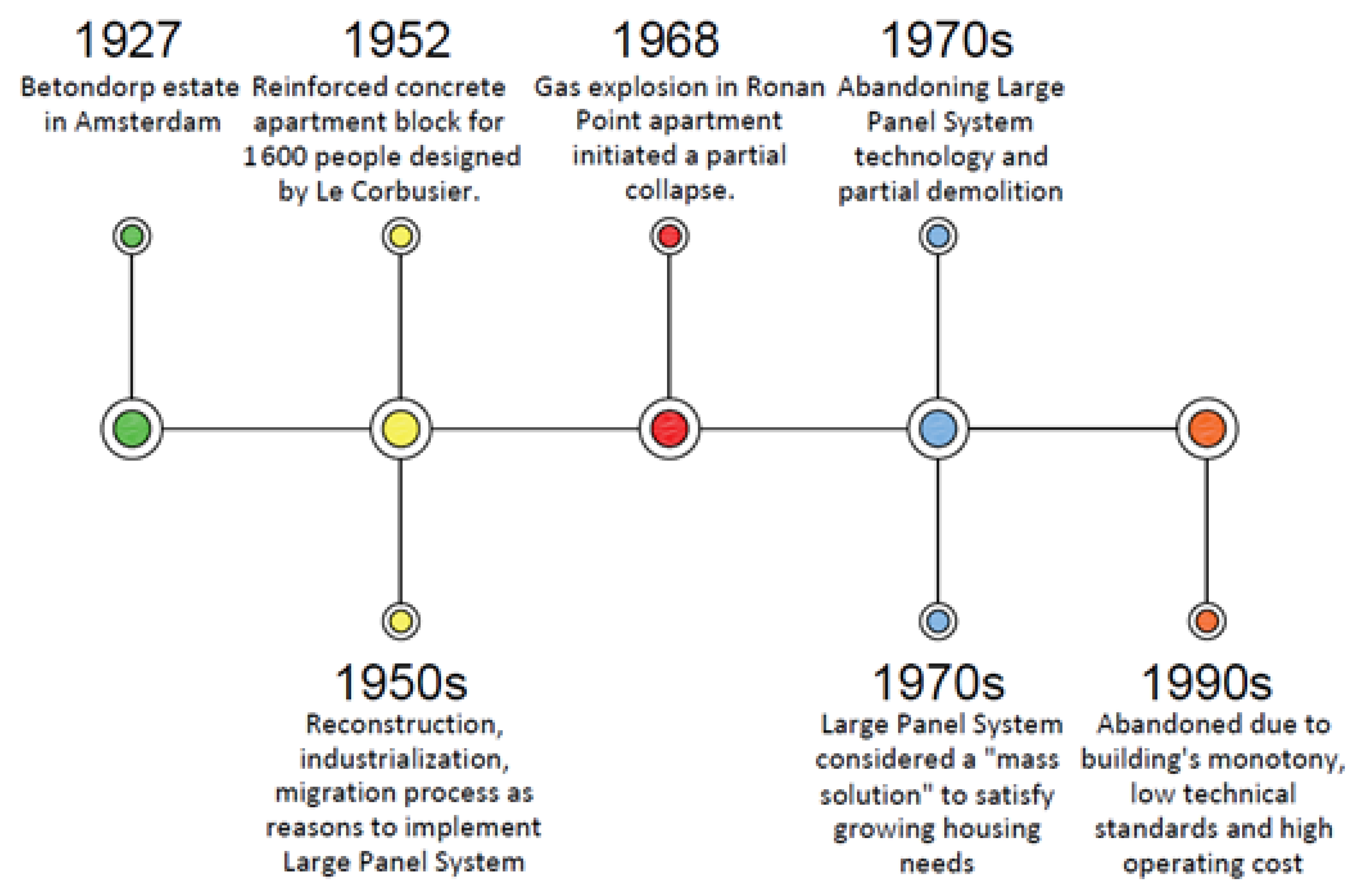
After the construction boom period involving LPS technology in the 1960s, two main events occurred: in 1963 many LPS buildings in Skopje, North Macedonia, were destroyed because of the earthquake and, in 1968, the partial collapse of Ronan Point occurred due to a gas explosion. Both events led, ultimately, to the creation of huge amounts of waste [
48]. After that, attention was focused on the need of addressing abnormal loads in the design of towers and joints, the weakest points in the structure, in order to prevent accidental collapses. Unfortunately, even today, regulations remain rather generic and there are no specific, exhaustive codes against abnormal loads. This and the poor quality of all construction stages show LPS technology in a very bad light. These are the reasons LPS technology was abandoned in Western Europe in 1970 (see
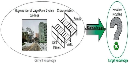
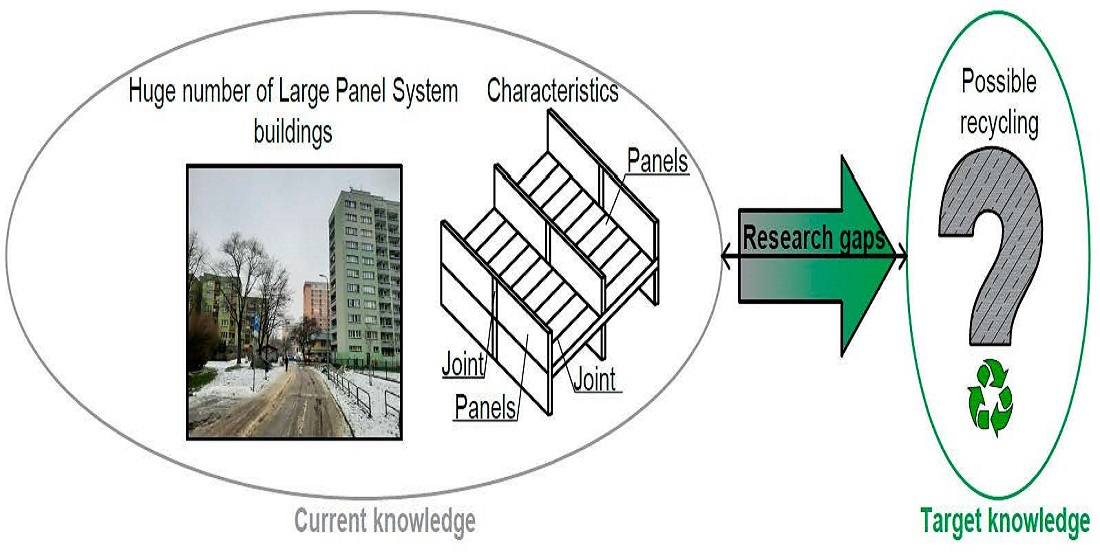
Section 3), and the authors believe similar processes will happen in Eastern and Central Europe. The disadvantages having an impact on LPS durability have been discussed in this section. Authors suggest there is an urgent need of evaluating waste from LPS buildings for recycling as some of the buildings will be destroyed. However, one of the still valid advantages is concrete load bearing panels are—even today—in good condition. In case of a demolition (planned or accidental), there is potential to re-use them in new constructions, which would be beneficial for the environment.
4.1. Seismic Resistance
Firstly, one should ask why LPS buildings are so vulnerable to earthquakes. During ground motions arising from earthquakes, the ductility of steel framed or in-situ concrete structures is responsible for dissipating energy. In LPS structures, developing flexural ductility is difficult to achieve due to the limited vertical continuity. A. Pall, C. Marsh and P. Fazio, in [
49], stated that for LPS buildings designed for earthquake resistance, the damage of developing cracks usually affects only the joints with minor or no damage to panels. A non-linear behaviour is applied to the entire building along the joints, while the panels remain in the elastic range. The suggestion was that panel connection should be maximized for energy dissipation capacity since it is the only location possible for this process. In [
50], A. Pall suggests that the vertical joints are the most suitable for it. Under the flexible action of the cantilevered shear walls, even after an energy dissipation slip, they can return to their previous position. To the best of the authors’ knowledge, no jointing system in 1980 and before could function as an efficient means of energy dissipation and at the same time fulfil basic design assumptions and carry the usual service loads without exceeding the elastic range. Thus, A. Pall, C. Marsh and P. Fazio, in [
49], concluded that only developing the limited slip bolted joint (
Figure 8) meets the requirements of an efficient energy dissipating connection with elasto-plastic behaviour and stable hysteretic characteristics.
Unfortunately, especially in the beginning of designing LPS buildings, in areas where earthquake is marked as a major risk, because of no codes available, seismic resistance of buildings was no major concern. As an example, in Bosnia and Hercegowina, structures built up to about 1965 had no seismic code applied, as no such regulations existed in that time there [
51]. Another example is North Macedonia, where a lot of LPS multi-storey family houses suffered a wide range of damage or collapsed, implicating serious causalities during the 1963 earthquake [
52]. The remaining ones were subject to structural rehabilitation and strengthening by means of inserting new extra horizontal and vertical reinforced concrete strips and throwing in supporting pillars within massive structural walls [
53]. After 1963, LPS buildings in North Macedonia started to be better quality and safer to resist strong seismic activity in the region. According to the survey, buildings that were built after the earthquake (the most in the 1970s, around 70% of national stock) are mostly in good condition [
54,
55]. Still, no evidence was found that LPS waste from the earthquake was somehow re-used or recycled, which would be beneficial if such events ever occurred again.
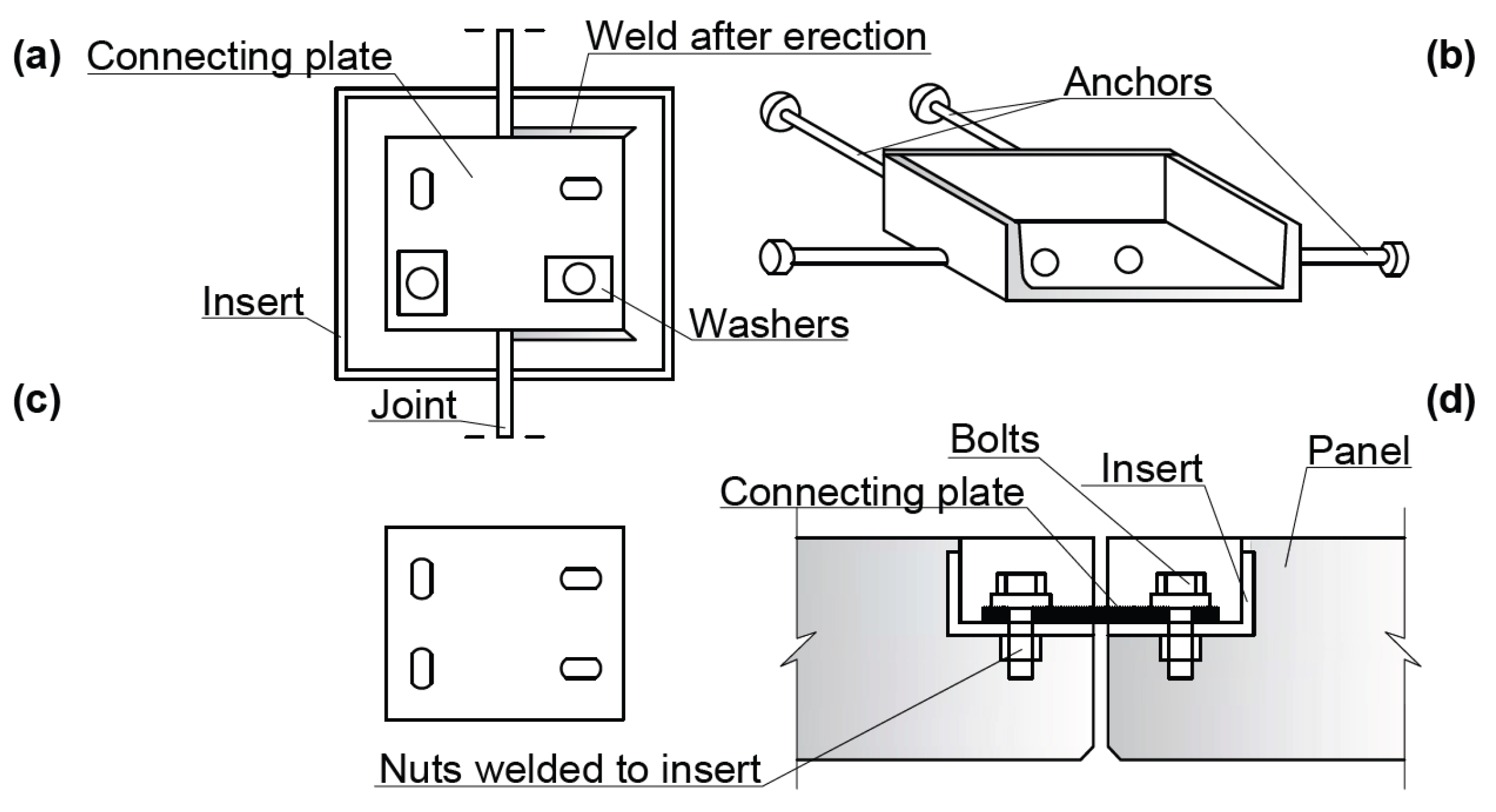
Figure 8.
Details of limited wall-to-wall slip bolted joint: (
a) elevation (
b) insert (
c) connecting plate (
d) section (based on the information provided in [
53]).
Figure 8.
Details of limited wall-to-wall slip bolted joint: (
a) elevation (
b) insert (
c) connecting plate (
d) section (based on the information provided in [
53]).
4.2. Structural Integrity and Progressive Collapse
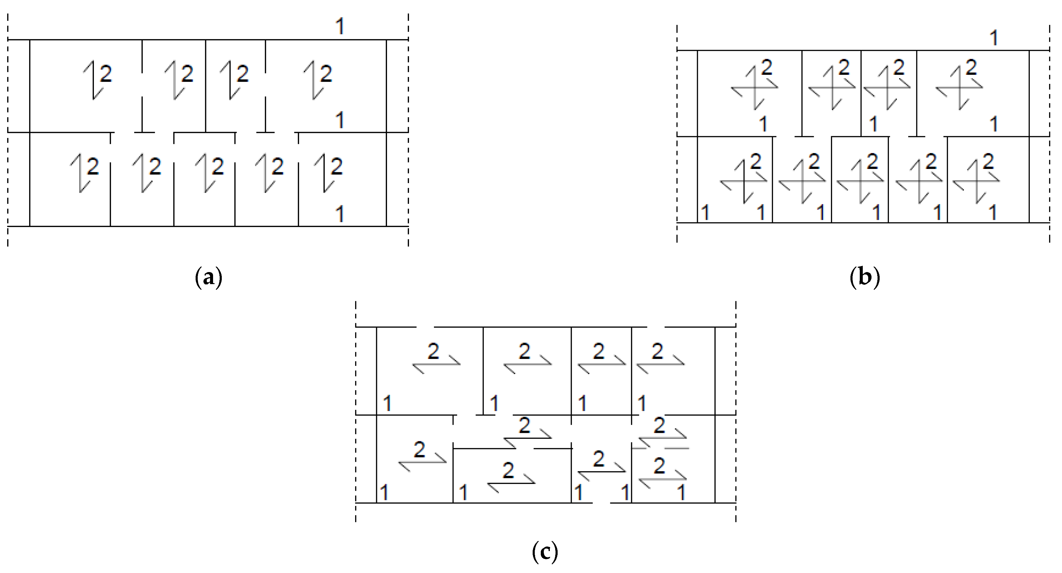
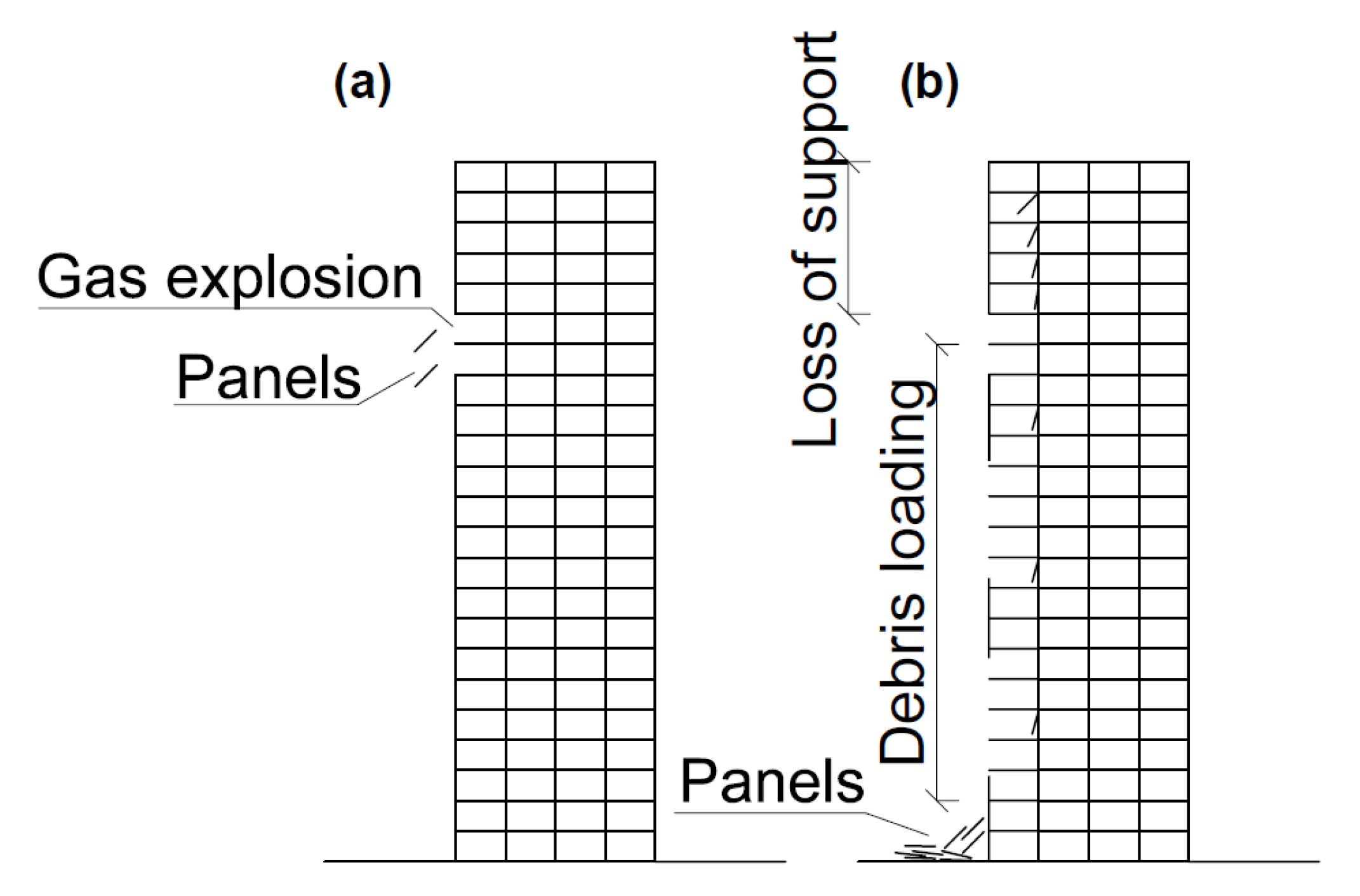
The Ronan Point example showed that progressive or disproportionate collapse (
Figure 9) occurs when a small part of the building is damaged by any form of abnormal load, and the whole structure losses its stability. LPS buildings are structures vulnerable to it, lacking flexural ductility and continuity [
56]. Because identifying and eliminating the hazard can be in some cases impossible, designing all elements to be robust to withstand abnormal loads is expensive; the most acceptable solution seems to be designing alternative paths to redirect the load while the local failure occurs [
57].
In order to develop a design for alternative load paths, a maximum damage volume or area must be defined. It can be achieved using [
58]:
direct approach (notional removal of structural elements, accurate but troublesome and time-consuming);
indirect approach (seeking and verifying alternate load paths, allows to evaluate indirect design, can be applied to many forms of structure).
Because of the structure with vertical and horizontal joints, other research studies lean towards the indirect approach in the case of LPS buildings [
57,
58].
In the 1970s, the Portland Cement Association (PCA), under the sponsorship of Housing and Urban Development (HUD), conducted research on the structural integrity and progressive collapse resistance of LPS structures. The results of their work are shown in
Table 2 and
Table 3.
Table 2.
Results of tests by the Portland Cement Association (based on the information provided in [
59,
60,
61,
62,
63]).
Table 2.
Results of tests by the Portland Cement Association (based on the information provided in [
59,
60,
61,
62,
63]).
| Analysed Element | Testing | Results |
|---|
| Cantilever behaviour of walls while removing a panel | Scale model depicting a six-storey building where five of them acted as a cantilever over the removed wall. The loading included floor dead load, partition dead load and 1/3 of the live load for the catastrophic condition | The cantilever behaviour of the walls is the main mechanism for unfolding alternate load paths. The cantilever rest moment depends on the tension at the joints on each storey and the compression at the lowest level. |
| The slab suspension mechanism | Removal of the support between two full-size floor slabs (jointed in the centre) | The slab suspension provided an additional alternate load path. Tensile joints above the damaged area provided partial support for the load. |
| Horizontal joints, the transmission to the vertical loads and the potential for wall splitting | Horizontal joints with platform framing. The analysed properties: mortar strength, amount of wall transverse reinforcement, filled or unfilled slab cores, applied moment and rotation | Results enabled the design of guidelines for the joints based on the variables investigated. |
Table 3.
Horizontal and vertical joints–recommendations based on results (based on the information provided in [
64,
65,
66,
67,
68]).
Table 3.
Horizontal and vertical joints–recommendations based on results (based on the information provided in [
64,
65,
66,
67,
68]).
| Name of the Joint | Role | Characteristics |
|---|
| Transverse joint | To transfer vertical shear from the walls above the damage to adjacent walls in the line of the damaged wall by providing cantilever and beam action | To be installed in floor and roof systems and over interior wall supports and between members and exterior walls, the joints should provide a nominal strength of 2.03 kNm (1500 lb*ft) with enough shear strength to prevent horizontal panels from sliding. Spacing of bearing walls should also be the maximal spacing of joints perpendicular to floor or roof slab spans. |
| Longitudinal joint | To develop membrane action of the floor | Spacing of the joints parallel to the span of the ceiling or the roof slab should be at intervals of maximum 3 m. It must be ensured that the forces are transmitted around the openings. |
| Vertical joint | To develop suspension action on ineffective walls to reduce debris load | To be installed in all walls and along the height of the building, the joints should provide a nominal tensile strength not less than 4.07 kNm (3000 lb*ft). Each panel should have at least two joints. |
Figure 9.
Problems with structural integrity in LPS buildings: (
a) immediate local damage followed by (
b) progressive collapse (based on the information provided in [
64]).
Figure 9.
Problems with structural integrity in LPS buildings: (
a) immediate local damage followed by (
b) progressive collapse (based on the information provided in [
64]).
Currie et al. [
65] defined typical defects of joints in LPS buildings: lack of or poorly compacted dry-pack, reinforcement bars and anchors not correctly located or lapped in the joints, small diameter bars and their different end treatment or reinforcement cut-off or bent back from the concrete element, all resulting in weak connections. Although, after the Ronan Point collapse, efforts have been made to require a minimum level of resistance to progressive collapse, they remain rather generic and there are no specific, exhaustive codes against abnormal loads [
14]. Thus, there is still a possible danger when an accident generates huge amounts of waste that must be disposed of.
4.3. Reliability and Fire Safety
Folic, Laban and Milanko [
58] investigated large panel system residential buildings in three countries: Bulgaria, North Macedonia and Serbia, in terms of reliability and sustainability. According to their research, most of the LPS buildings in the Balkans lack essential fire safety regulations. The authors suggest that improving fire protection means and analysing risks should be key aspects during renovations. However, even when improved fire regulations over time were mandatory to follow, the authors stated that in many cases they failed to be implemented. For example, in North Macedonia, according to [
57,
66], only 30% of LPS buildings are being well maintained, repaired and renovated over time, despite the fact that numerous amendments to fire safety regulations have appeared since erecting the estates. In Serbia, only in 1984 did detailed regulations on fire protection appear, even while using LPS technology since 1960. Even then, these rules were often being neglected, reduced to the simple solution and extrapolated to larger models [
58]. Still, one of the key problems is the lack of maintaining buildings in terms of fire safety, even if it is required by law [
67].
In 2011, three LPS buildings, each in a different Balkan country, were comparatively analysed and evaluated (
Table 4). Unfortunately, despite constant renovations and maintenance, no analysed buildings met the current fire safety regulations. If many LPS buildings (according to the literature survey) are not properly maintained, based on their disadvantages (see
Section 4.1 and
Section 4.2), they might not fulfil their planned service life.
4.4. Defects during Design, Execution and Exploitation Stages
Although the LPS structure remains one of the most significant construction technologies of the 20th century, it is impossible not to mention the disadvantages of all construction stages, especially when analysing buildings from the post-war period 1945–1990, as presented in
Table 5.
Although initially, LPS buildings appeared to be innovative and a relatively cheap housing option for the working class, the perception of the large panel system has changed dramatically over the years. The prefabricated elements were often heavy and required to be delivered to the construction site by expensive means of transport, adapted to heavy and large-size elements. Loading, unloading and assembly required the use of a crane. A significant problem, especially for the construction industry of socialist Poland, was the low quality of workmanship. Salaries were low and production plants, together with construction sites, were characterized by poor work organization. A large percentage of elements, which did not meet the dimensional standards, often disorganized work on the site. Some of the problems appeared only in ready-made facilities, and therefore remedial actions were taken, such as additional board anchoring or patching cracks with tar sealants. The classic large panel was uniformly flat, and slight damage to the edges resulted in gaps that were difficult to fill.
LPS housing estates are generally grey, often built with the use of materials harmful to health—e.g., asbestos. Flats are small and too expensive to operate (related to the fact that an uninsulated large slab has very high thermal transmittance, thus heating costs are very high). Despite many improvements, the joints between panels are still difficult to seal. The wall thermal insulation standards were over three times lower than those required today [
70]. Insulating buildings began in the mid-1980s, and this tendency intensified in the later years due to a significant increase in the cost of heat supplied to apartments. In many housing estates, works are carried out to improve the insulating properties—usually the facades [
71]. However, a layer of insulation with a thickness of several centimetres, and a new plaster and colour, can change the appearance of a building. Many such renovations are controversial because the original facade is lost, and new colour and patterns are sometimes inconsistent with modernist architecture.
4.5. Concrete Load-Bearing Elements
It is worth noticing that the research studies below, in many cases, focus on other topics connected with concrete (for instance, durability of interlayer connections or insulation in external sandwich walls). Concrete itself is hardly ever the primary case in studies on large panel system buildings. The authors of various studies agree that the concrete is still in satisfactory condition. Possible cracks and scratches in concrete and unsealing of partitions are usually caused by reinforcement defects of structural and textured concrete layers and methods of their bonding.
Jasiczak and Girus, in [
72], examined the external layer of the external wall of the edifice completed in 1986 with LPS technology (R-76, version of
Rataje closed variant) with 13 overground storeys in Poznan, Poland. The thickness of triple-layer curtain wall layers were: external concrete layer of 6cm (expanded clay concrete C12/15 or standard concrete C16/20), thermal insulation of 9cm and structural concrete layer of 21 cm (expanded clay concrete C12/15 or standard concrete C16/20). The structure was transverse and longitudinal, with 4.8 m and 2.4 m spacing of load-bearing walls. The condition of concrete was determined by hardness and compressive strength. For a non-destructive test, authors used a Schmidt sclerometer. The tested concrete was in the air-dry state, and the temperature was 20–25 °C. The surface was prepared for measurement by splitting the surface layer of grit and grinding with smoothing with a wire end. Significant differences may result from conducting the test on the not-rigid-enough component (minimum thickness of the element, according to recommendations, should be 100 mm). Results are presented in
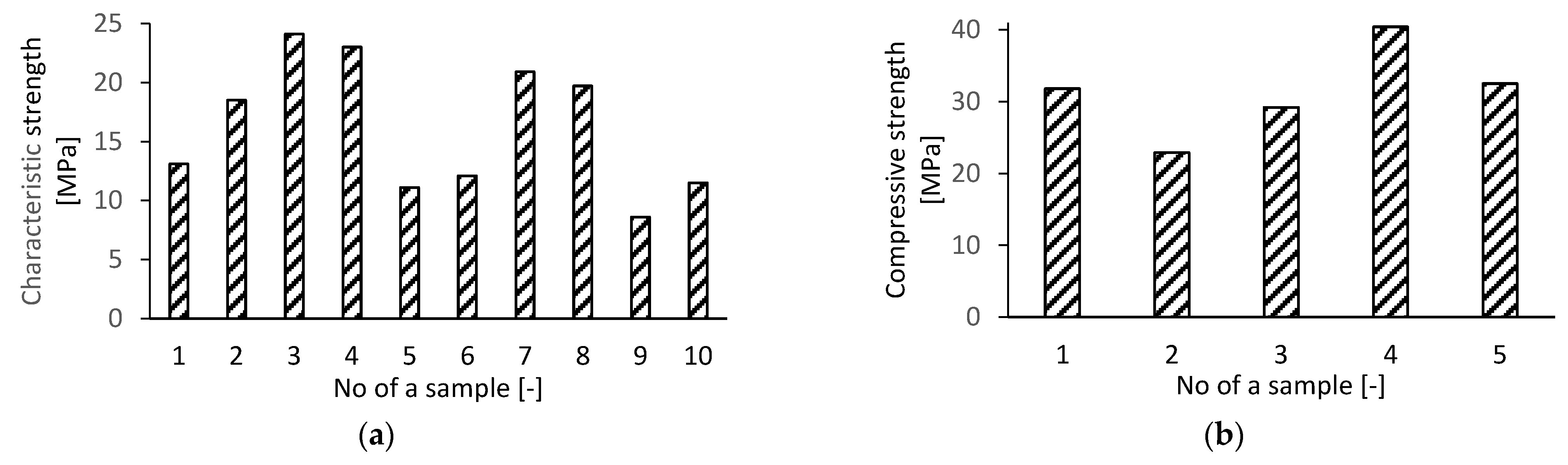
Figure 10a. To determine compressive strength, the cored boreholes of 43–44 mm diameter were taken from the same structure. In order to avoid reinforcement in the samples, the location of steel rods was determined using a ferromagnetic device. For testing, a universal testing machine SATEC was used, and the results are shown in
Figure 10b. Errors during construction stages, years of exploitation and poor maintenance [
73] resulted in a great number of scratched panels, falling grit, visible hangers and pins in the examined building. However, results regarding the state of concrete are favourable.
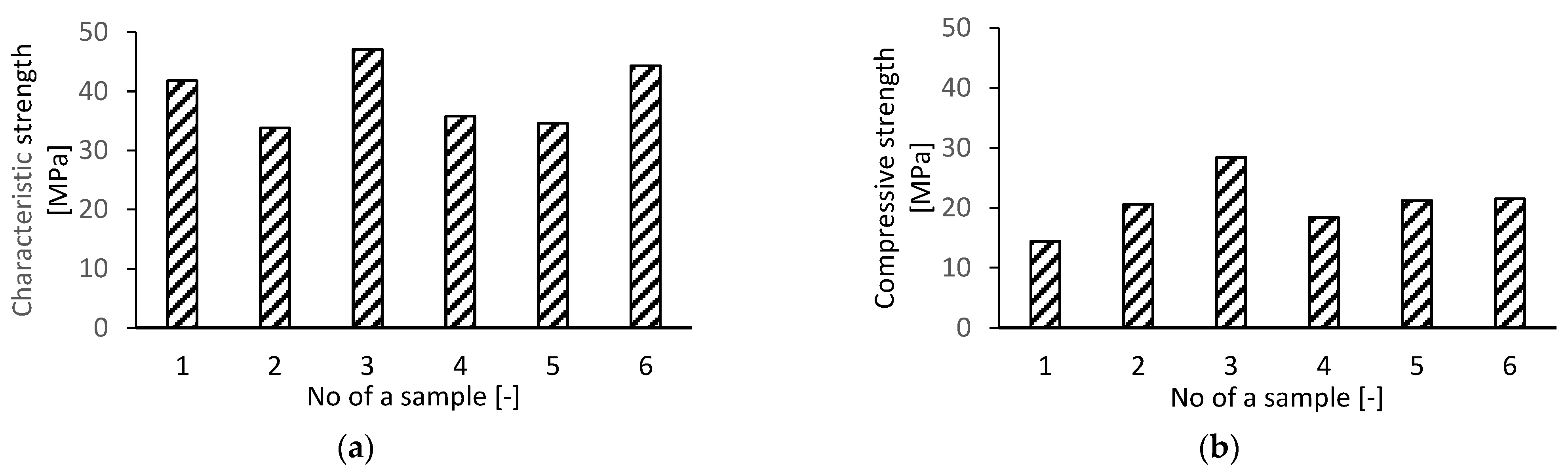
Girus [
74] evaluated the external layer of the external wall of the edifice completed in 1988 with LPS technology (SL-85, version of
S-Sz closed variant) with five overground storeys in Poznan, Poland. The thickness of triple-layer curtain wall layers were: external concrete layer of 8 cm (expanded clay concrete C12/15 or standard concrete C16/20), thermal insulation of 6cm and structural concrete layer of 22 cm (expanded clay concrete C12/15 or standard concrete C16/20). The structure was transverse with 4.8 m and 2.4 m spacing of load-bearing walls. To determine compressive strength, again, the cored boreholes of about 44 mm diameter were taken from the structure. The test was carried out on the Instron SATEC testing machine. Differences in strength, shown in
Figure 11a, can be related to concrete segregation and depend on the arrangement of the expanded clay aggregate [
74]. However, in most cases, the results are satisfactory and confirm the design assumptions.
Bacharz et. al. [
75] analysed loggia wall in W-70/M-K system in Kielce, Poland. The precast walls were made of concrete class C12/15 (B17.5). To evaluate the compressive strength of concrete, N-type Schmidt hammer was used at six points. The results are presented in
Figure 11b and indicate that the concrete class was C25/30 (B30) and so higher than the assumed design class.
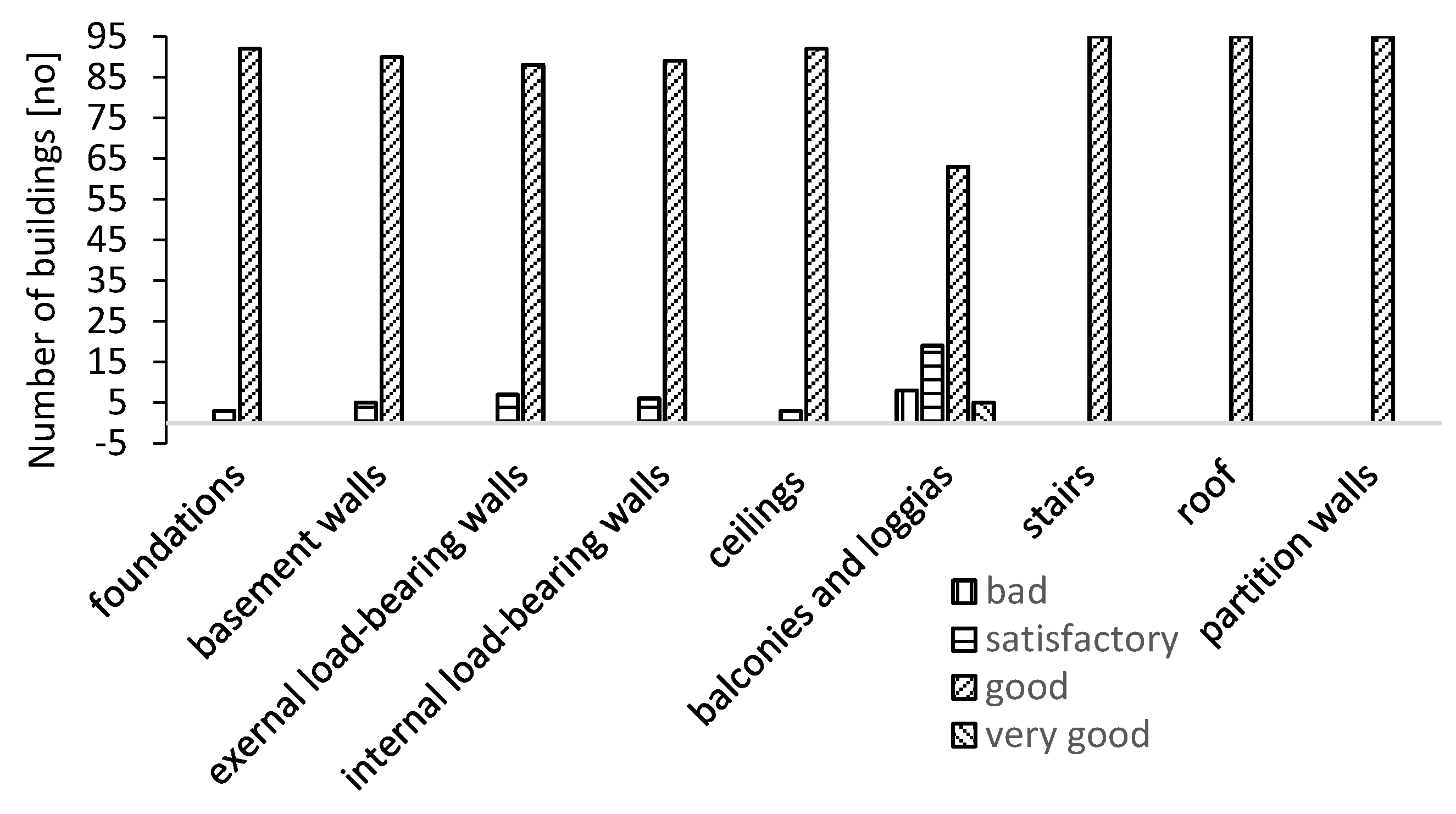
Knyziak [
76] analysed the durability of 95 apartment buildings in Warsaw, Poland—33 in large block technology and 62 in large panel technology. Although he noted several defects, including insufficient thermal insulation, devastated window frames, bad condition of water drains and old building’s infrastructure, the conclusion was that concrete load-bearing elements are in good condition. The results from the research are shown in
Figure 12. The vast majority of elements present good condition. The inspection was carried out according to [
77].
Knyziak et al. [
78] noted that the thickness of concrete in the façade layers often exceeded the design values. Although it resulted in reduction of thermal insulation and increase in weight, objectively speaking, there is a relatively thick layer of load-bearing wall made of good quality concrete.
Tofiluk et al. [
79], based on their own research and experience of other scientists, created a list of typical necessary work to perform in large panel system buildings as part of repairs and assuring the safety of exploitation. The list includes:
Strengthening of hangers fixing external panels;
Modernization of thermal insulation;
Improvement of acoustic insulation;
Replacement of improvement of old ironwork of balconies;
Replacement of dry rises.
The authors suggest that the main factor determining the technical usefulness of a structure is the deterioration degree of the foundation and load-bearing walls. However, the list of works to perform do not include improvement of concrete precast elements. The authors agree that concrete is in good condition.
Krentowski et al. [
80] examined the condition of external curtain walls used in common late LPS systems (1980s) in Poland. He stated that the durability of the external partition (concrete structural layer, thermal insulation, outer layer of textured concrete) is highly influenced by the quality of the connections of layers. The state of the external partition is important as it affects LPS resistance to the possibility of a progressive collapse of the whole building. The conducted research and observations of buildings proved that the tested concrete of precast wall elements had sufficient tightness. It has been noticed that the internal structural concrete layer is not exposed to the direct weather influence and, from the external side of the building, it is covered by insulation material. In terms of durability estimation, the work conditions of the wall panels are good.
Szlendak et al. [
81] presented the results of load capacity of the anchorage system connecting the textured layer with the structural wall.
The above statements seem true also for LPS buildings in other countries. In [
54], the authors analysed the durability of estates in Bulgaria, Serbia and Macedonia. In all three countries, despite a lot of deteriorations (especially connected with façade), concrete bearing elements are in good condition. Additionally, thickness of the concrete in the façade layers often exceeded the design values.
Botici et al. [
82] used three large panel typologies: T744R, 770 and 1340 to determine possibilities of sustainable retrofitting. The reinforced concrete structural layer was 11 cm thick for T744R and 1340, while 9.5–12 cm for 770. The external layer was 5–6 cm for all systems. All layers were made with C16/20 equivalent concrete class and preserved the strength at the time of research.
Muntean et al. [
83] analysed the building with one of the most popular typologies in Romania—770. According to the authors, this five-storey residential unit built during the 1970s, offered 14 cm C12/15-equivalent concrete panels in the interior floors. The exterior wall panels were made of two layers of C16/20-equivalent concrete class. The ultimate cubic compressive strength of concrete for the tested wall panel was 17.5 MPa [
84]. Joints between the panels were made by welding the concrete steel reinforcements and C18/22.5-equivalent concrete class.
From previous paragraphs, one can assume that large panel system buildings constructed during the 1945–1990 period approach or have already exceeded their service life. However, from the information presented in this section, one can find out the concrete used in the construction of panels seems to be in satisfactory condition. This creates opportunities of re-using or recycling panels.
Figure 11.
Results of concrete strength parameters: (
a) on loggia wall, using Schmidt hammer, based on [
80] (
b) on external wall, using SATEC machine (based on the information provided in [
79]).
Figure 11.
Results of concrete strength parameters: (
a) on loggia wall, using Schmidt hammer, based on [
80] (
b) on external wall, using SATEC machine (based on the information provided in [
79]).
Figure 12.
Technical state of bearing elements (based on the information provided in [
76]).
Figure 12.
Technical state of bearing elements (based on the information provided in [
76]).


