Article

Development of Psi Factors for Thermal Bypass Due to Insulation Gaps in Low-Slope Roofing Assemblies

National Research Council Canada, Ottawa, ON K2J5N8, Canada
*
Author to whom correspondence should be addressed.
Buildings 2022, 12(1), 68; https://doi.org/10.3390/buildings12010068
Submission received: 3 December 2021 / Revised: 7 January 2022 / Accepted: 9 January 2022 / Published: 11 January 2022
(This article belongs to the Section Building Energy, Physics, Environment, and Systems)

Abstract

:
In commercial roofs, the presence or formation of gaps could be due to improper installation, thermal expansion, and dimensional changes in the insulation boards. The heat loss from these gaps could lead to higher thermal transmittance in the roof assembly. The current research study conducted around 70 experiments to investigate the effect of gap height, gap width and gap offset on the thermal transmittance of the roofing assembly. The measured data showed that in a staggered insulation layout with a joint offset of 610 mm (24 in), formation of 6.4 mm (1/4 in) to 12.7 mm (1/2 in) gaps at the insulation joints could contribute to an average decrease of 2% to 9% in the effective R-value of the roof assembly. As the insulation thermal resistance increases or becomes thicker, the thermal losses in the roof assembly increase. Generalized gap impact curves were developed to provide the relation between gap parameters (i.e., gap widths and height) and the thermal performance of the roof assembly. The experimental data were further analyzed using the psi factor approach of linear thermal bridging generating thermal transmittance data to support the calculation of thermal bypass from gaps in the thermal roof design.

1. Introduction

In commercial buildings, roofs occupy a large portion of the surface area of the envelope. The typical components of a conventional roof assembly include waterproofing membrane, cover board, thermal insulation, vapor barrier, and roof deck. The thermal resistance of these roofing components and exterior and interior air films control the heat flow through the roof assembly. The thermal insulation is the primary component to provide resistance to heat flow within the roof assembly, i.e., the highest R-Value within the roof assembly. Therefore, the efficient use of thermal insulation materials in the building envelop thermal design remains one of the most effective ways of improving a building’s energy performance.
Over the decades, the North American roof insulation market has advanced. Insulations with R values ranging from RSI 0.07 to RSI 4.17 per cm (R-1 to R-60 per inch) [1] have been developed, and the industry is advancing with new-age insulation materials. However, the role of insulation has also evolved from its primary function of providing thermal resistance to fire protection, sound reduction, wind uplift resistance, drainage, and a surface for installing the waterproofing membrane. The governing factors for the thermal insulation selection in the commercial roof design include its thermal resistance value per inch, dimensional stability, compressive strength, thermal drifting, flexural strength, facer characteristics, and moisture performance. In addition, the insulation’s compatibility with other roof assembly components, i.e., its attachment within the assembly, is equally important when assembling the roof assembly components. Thus, selecting the appropriate insulation product depends on the designer.
The thermal resistance of insulation referred to as “rated R-value” in the ASHRAE 90.1 [2] is obtained at a reference temperature of 24 °C (75°F) when conducted per the ASTM C 518 [3] laboratory testing procedure. Using the rated R-value of the insulation, the required insulation thickness to design a code-compliant roof assembly is determined. The efficiency of this design process depends on the thermal effectiveness of the insulation as a component and as an integrated part of the roof assembly. In commercial roofs, the insulation materials usually take the form of 1219 mm × 1219 mm (4 ft × 4 ft) or 1219 mm × 2438 mm (4 ft × 8 ft) rigid boards. During the installation of these rigid boards to construct a roof assembly, gaps might exist between the boards with lower thermal resistance than the insulation itself. The heat transfer that bypasses the conductive heat transfer between two regions is called thermal bypass [4]. In roof assemblies, the thermal bypass is the heat loss through intentional or unintentional openings via air, heat, and moisture movement. A good example is the heat losses at the gaps in the insulation joints. These gaps lead to cold bridges at the insulation joints, complicating the heat flow analysis through the roof assembly.
The gaps between insulation boards can be formed due to several factors, including the following (Figure 1):
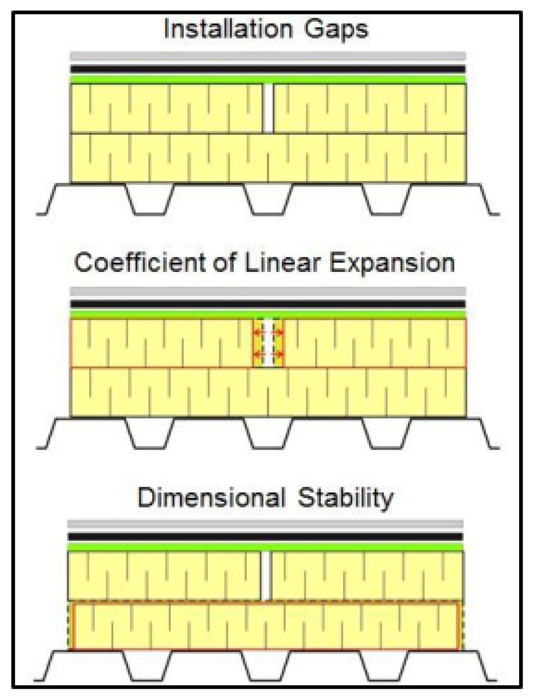
  • When the insulation is installed during the roof assembly construction, it is not uncommon to see between 1.6 mm (1/16 in) and 3.2 mm (1/8 in) gaps between the insulation boards. These gaps can be further compounded by the deficiencies in the manufactured boards;
  • The daily and seasonal temperature variations in the life cycle of the roof assemblies can cause the insulation boards to expand or contract depending on their coefficient of expansion. These changes in the board dimensions might not be permanent, and the boards could return to their original dimensions. However, this expansion and contraction leads to gap formation and transfers stresses to the attached components within the roof assembly;
  • The dimensional stability of the insulation boards could also lead to gaps between the boards. In simple terms, dimensional stability is the material’s permanent change in dimensions (length, width, and thickness) in response to the changes in temperature and humidity conditions to which it is exposed;
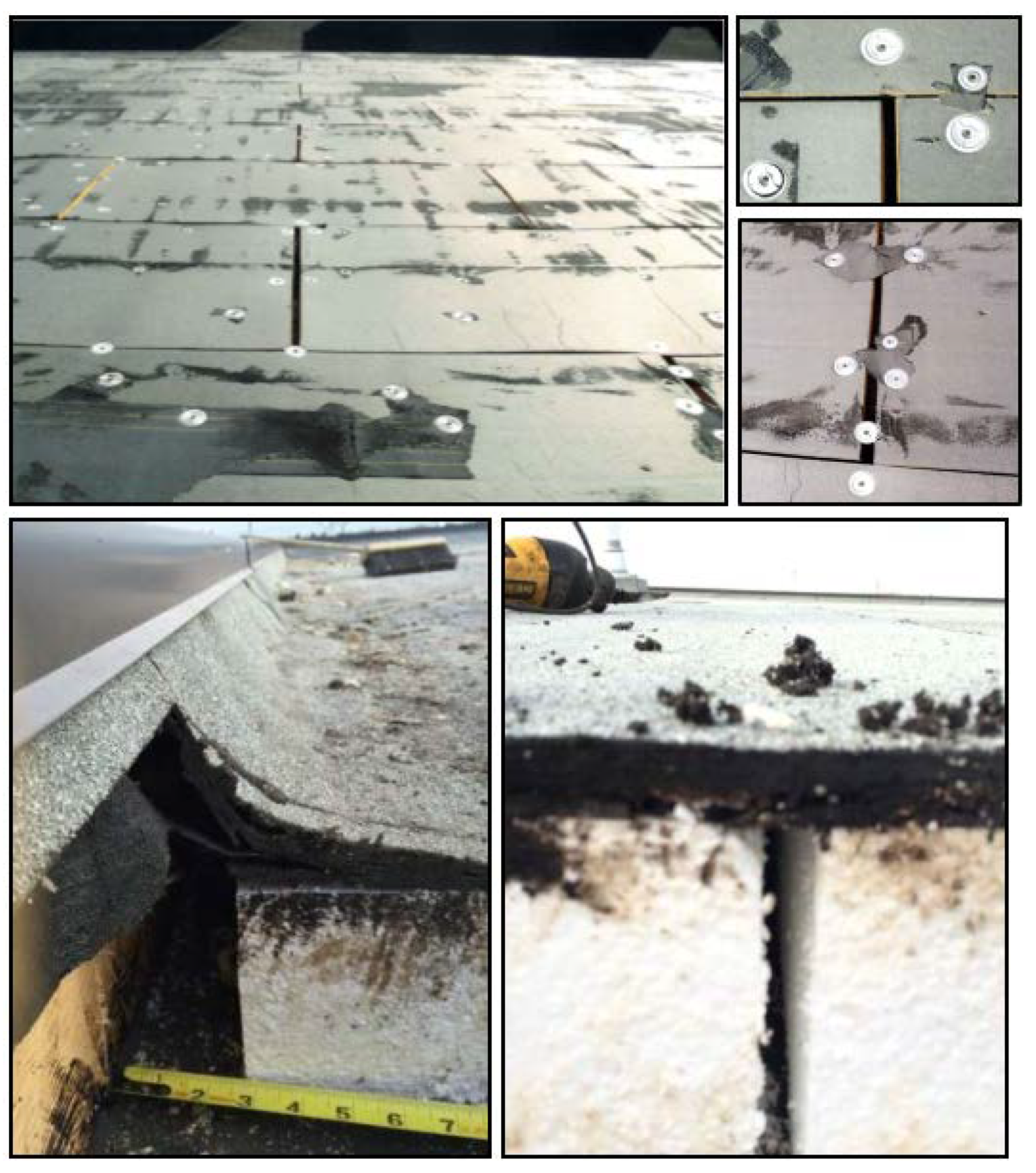
  • Gaps in the range of an inch or greater at the insulation joints may seem far-fetched, but the reality is that these gaps exist. Figure 2 shows the field examples of the magnitude of gap formation in commercial roofs that further emphasizes the importance of considering gaps in the thermal design of roofs.
The gap characteristics such as size, shape, and location can impact the thermal performance of the roof assembly. Therefore, if the gaps are not considered in the roof design, there could be a mismatch between the designer’s roof thermal design that he has put on the paper and the roof design installed and operating in actual service conditions.
The effect of air gaps on the thermal properties of walls has been investigated and presented in research papers throughout the literature (Chebil et al. [5]; Bankvall and Sikander [6]; Qin et al. [7]; Šeduikytė and Paukštys [8]; Šadauskienė et al. [9]; Kosinski [10]; Kosinski [11]). However, there are no data on the thermal bypass through vertical air gaps formed in the thermal insulation layer laid horizontally in the conventional low-slope membrane roofs.
Lewis [12] investigated the effect of gaps between insulation boards on thermal transmittance using analytical modeling and limited validation through experimental testing. He developed a relationship between gap width and the percent increase in thermal transmittance through roofing systems. The study was conducted with 2 insulation layers having a through gap and staggered gap configuration for gap widths up to 25.4 mm (1 in) wide and 57 mm (2 1/4 in) in height. The tests were conducted on only fiberglass insulation.
Hedlin [13] conducted field studies on conventional and protected membrane roofs to measure heat loss through insulation joints. Measurements were made on extruded polystyrene having butt joints, beveled butt joints, and shiplap joints. The butt joint ranged up to 25.4 mm (1 in) wide, the beveled joint was 28 mm (1.10 in) at the deck, and the shiplap was a 3 mm (1/8 in) joint. The heat flow through the insulation joints was measured by placing heat flux transducers at the underside of the deck at various locations to measure the heat flow through the insulation joints. The measured heat loss through the 2.5 mm (3/32 in) and 12.7 mm (1/2 in) butt joints was about 4% and 17% in conventional roofs. Measurements in the protected membrane roofs with butt joints ranging from 2.5 mm (3/32 in) to 25.4 mm (1 in) showed a heat loss ranging from 4 % to 35%. For the beveled butt joint tapering from 3 mm (1/8 in) to 28 mm (1.10 in) width at the deck, the average heat loss from tests was 14.4%. The 3 mm (1/8 in) wide shiplap joints measured the smallest increase in heat loss between 1 and 2%.
Petrie et al. [14] investigated the impact of insulation gaps and fasteners on the thermal performance of low-slope roofs with polyisocyanurate insulation. Testing was conducted on single- and double-layer insulation boards 51 mm (2 in) thick with a gap of 25 mm (1 in) following the ASTM C1363 [15] at various mean temperatures in addition to tests with fasteners. The 25 mm (1 in) gap between insulation boards resulted in a 15% loss of thermal resistance for 2 layers of insulation boards and a 17% loss in single-layer tests.
Šadauskienė et al. [16] determined the impact of vertical air gaps on the effective thermal conductivity of the thermal insulating layer through experimental testing and calculations. The investigation was conducted on single-ply mineral wool boards. The thermal measurements of 50 mm (2 in) thick insulation boards with air gaps widths of 3 mm to 20 mm (1/8 in to ¾ in) showed thermal conductivity increases with increased air gap widths. Moreover, the effective thermal conductivity coefficient proportionally increases as the height of the air gaps increases.
Concerning standards on thermal bridging, including thermal bypass due to insulation joints, ISO 14683 [17] provides the procedure for determining the overall heat transfer coefficient as follows:
H D = i A i U i + k l k Ψ k + j χ j
where
HD is the building direct transmission heat transfer coefficient in W/K (Btu/(hr·ft·°F))
Ai is the area of the element i of the building envelope, in m2 (ft2)
Ui is the thermal transmittance of element I of the building envelop in W/(m2∙K) (Btu/(hr·ft2·°F))
lk is the length of linear thermal bridge k, in m (ft);
Ψk is the linear thermal transmittance of linear thermal bridge k, in W/(m∙K) (Btu/(hr·ft·°F))
χ j is the Chi-factor of point transmittance of the fastener used in the particular assembly (W/K, Btu/(hr·ft·°F))
The linear thermal transmittance, Ψ, provides an approach for assessing the impact of gaps in insulation joints within roofing assemblies.
Building energy codes, such as [2,18,19], provide minimum performance requirements for the design of energy-efficient roofs. These codes present approaches to determine the roof assembly’s thermal transmittance (U-value), limited to opaque roof assemblies. However, they do not provide any design criteria for thermal bridging and thermal bypass, omitting major thermal design parameters for energy-efficient roof design. The reasons for the omission could include the absence of data and a lack of information demonstrating the significance of thermal bridging and thermal bypass in roof thermal design.
The National Research Council Canada (NRC) developed an industry consortium, “Energy Resistance of Commercial roofs” (ERCR), to enhance the energy efficiency of the commercial roof designs. These partners include the National Roofing Contractors Association (NRCA), Canadian Roofing Contractors Association (CRCA), Roofing Contractors Association of British Columbia (RCABC), Roofing Consultants Institute (RCI now IIBEC), Sika, Trufast, EPS Industry Alliance, Rockwool, Soprema, 2001 Company, Natural Resource Canada—Program of Energy Research and Development.
The ERCR project had two major tasks. Task 1 evaluated the effective thermal resistance of current roof designs and validated their compliance with the energy code requirements using large-scale testing of roofing specimens of 6.1 m × 2.4 m (20 ft × 8 ft). Task 2 focused on quantifying the thermal bridging due to metal fasteners and thermal bypass from gaps between the insulation boards.
The research outcome of Task 1 is published in a conference paper [20]. The impact of thermal bridging quantified from Task 2 is detailed in the paper [21], while a roofing magazine article reported the preliminary results on insulation gaps [22]. This paper extends the article [22], providing additional research results of the thermal bypass study.
As mentioned above, currently, the building codes do not provide any guidance for thermal bypass in the thermal design of roofs. This paper aims to present codifiable research data on the influence of vertical air gaps on the effective thermal resistance of the commercial roof assembly. The research information is presented in two parts. Part 1 discusses the experimental investigation on quantifying the thermal bypass from the gaps at the insulation joints. It identifies the thermal losses in staggered joints and cross joints and the combined thermal losses from fasteners and gaps in roof thermal design. Part 2 focuses on developing Psi factors for the characterization of the gaps. Psi value is a measure of linear thermal heat transmittance through a length of material or assembly, usually at a roof-wall junction. In the current project, the Psi value approach has been adopted to the thermal bypass from the gaps at the insulation joints. From the experimental data, Psi factors for the different gap types (width and thickness) have been developed to best model the thermal transmittance of a roofing system.

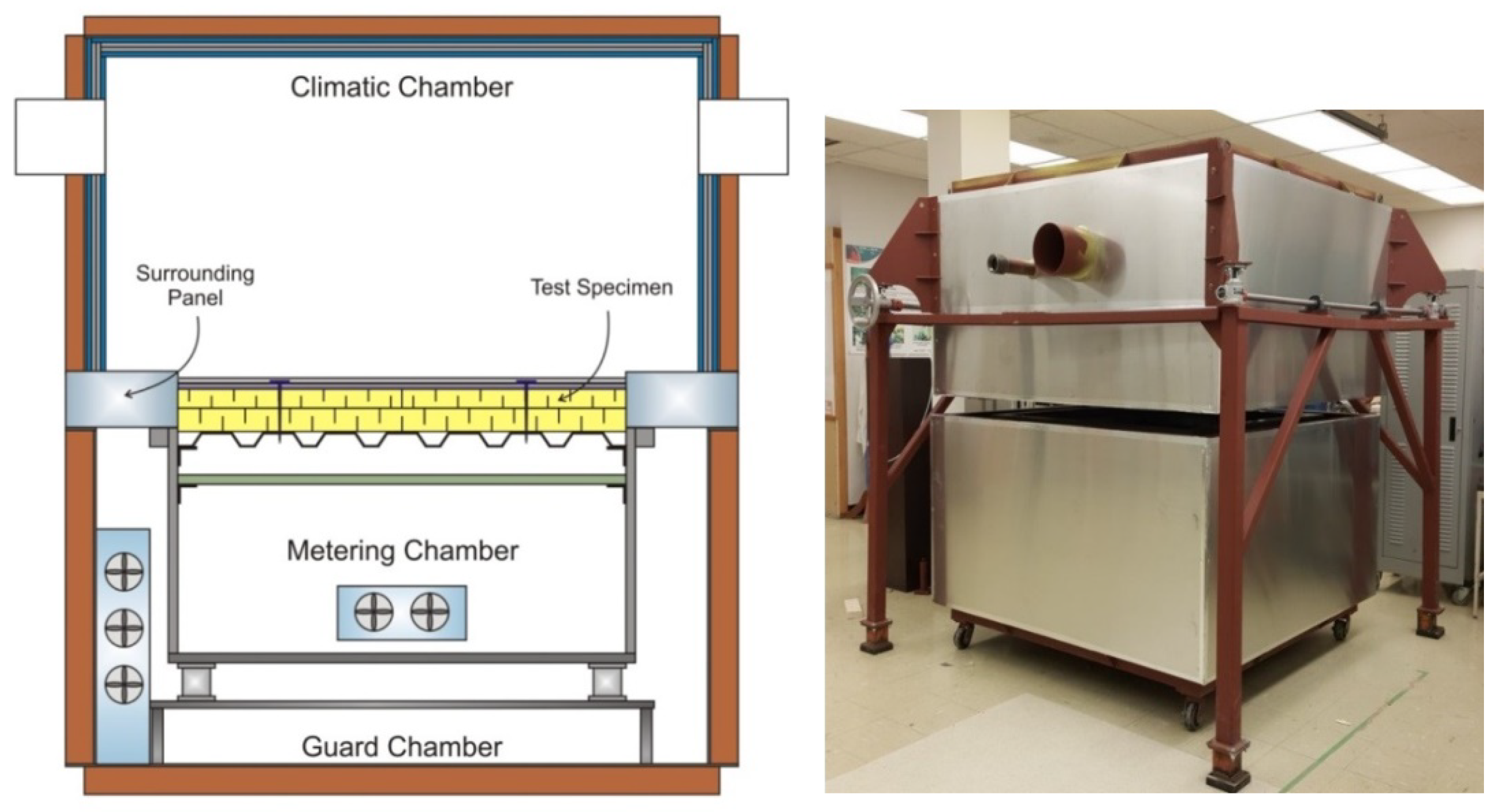
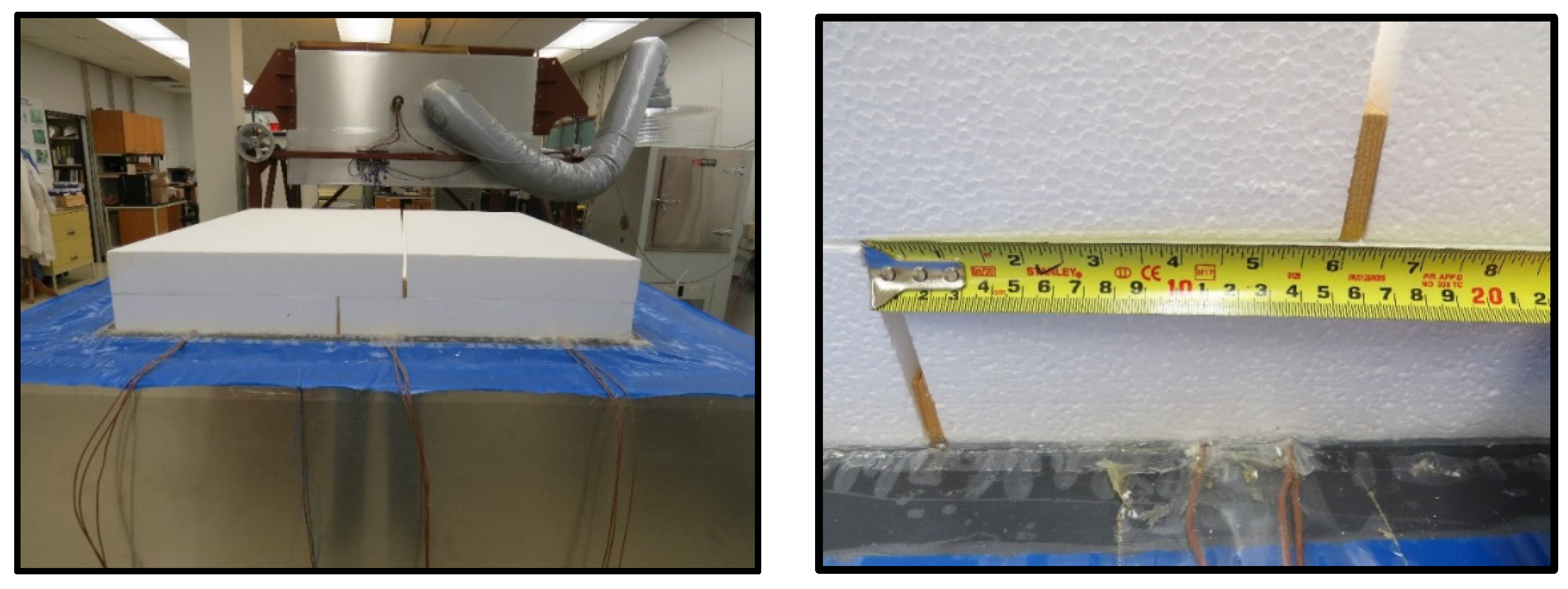
2. Part 1: Experimental Approach

The thermal bypass, due to insulation gaps in roofing assemblies, was quantified using a 1.2 m × 1.2 m (4 ft by 4 ft) guarded hot box apparatus (GHB) (Figure 3). The GHB has been designed, constructed, and calibrated following the ASTM C1363 standard [8]. All of the thermal bypass experiments were conducted at a mean temperature of 24 °C (75 °F).
The ERCR steering committee members designed multiple conventional low-sloped membrane roofing systems by including three commonly used conventional insulations. The insulation types used in the study were glass-fiber-reinforced organic facer polyisocyanurate (Type II), Expanded Polystyrene, EPS (Type II in Canada per S701.1), and Rockwool. In addition, the consortium members also provided the rated R-value of their insulation products The R-value was used to determine the overall insulation thicknesses (top and bottom layers) for the 3 design categories, R25.21, R30.21, R35.21, as shown in Table 1. The thermal resistance of the insulation was determined through the heat flow meter (HFM) test apparatus following ASTM C518-17 [3]. Insulation boards from each design category were tested individually and then as an assembly of boards (two layers) depending on the thickness limitation of the HFM. Ref. [12] provides more information selecting these design categories and the thermal characteristics of the insulations used in the ERCR study.
All of the designed assemblies comprised two insulation layers. The insulation layers were installed by arranging the boards in a staggered vertical alignment by offsetting the joints. This layout is referred to as staggered joints (Figure 4). A total of 2 joint offsets, 1 at a distance of 610 mm (24 in) and the other at 152 mm (6 in) apart (Figure 4 and Figure 5) were evaluated in the current study. For each joint offset, testing was conducted for 3 cases: (1) butt joint with no gap between the insulation boards, (2) gap width of 6.4 mm (1/4 in) at the insulation joints and (3) gap width of 12.7 mm (1/2 in) at the insulation joints. In addition, to assess the impact of cross joints (one joint in the bottom layer of insulation crossing with a top joint in the other direction), testing was conducted on the EPS R-26 System for the three test cases.
As mentioned above, apart from determining the thermal bypass at insulation joints, the research focus of Task 2 of the ERCR consortium was also the quantification of thermal bridging from roofing fasteners [21]. Therefore, additional testing was carried out in the current study by combining thermal bypass and thermal bridging in the roof thermal design. The testing was performed on all 3 insulation types with the R-31 designed roof assemblies. The insulation layout comprised 2 layers with a staggered joint offset of 610 mm (24 in). A gap width of 12.7 mm (1/2 in) for the thermal bypass was created at the joints. For thermal bridging, the insulation was mechanically fastened with 10 fasteners per board (Figure 4).
Table 2 lists the test matrix of all the tests conducted in the current experiment study.

3. Part 2: Numerical Analysis—Psi Factor Approach

Psi value is a meaure of linear thermal heat transmittance through a length of material or assembly. In the current project, the Psi value approach has been adopted to the thermal bypass from the gaps at the insulation joints.
Appendix F of the ISO 6946 [23] provides a simplified approach for quantifying the impact of point thermal bridges, including the thermal bridging due to mechanical fasteners penetrating an insulation layer. The corrected thermal transmittance, Uc, is determined as:
U c = U + Δ U f
where U is the thermal transmittance of the opaque assembly or assembly without fasteners, and Δ U f is the thermal correction due to the point thermal bridge of fasteners defined as:
Δ U f = n f χ
where n f is the number of fasteners per unit area in m2 (ft2) and χ is the Chi-factor of point transmittance of the fastener used in the particular assembly (W/K, Btu/(hr·ft·°F)).
This approach provides a means of normalizing the impact of fasteners on the thermal performance of the roof assembly and is valid in cases where the fastener is thermally connected to a component of high thermal conductivity, such as a metal roof deck, as was the case in this analysis.
When examining the case of thermal bypass due to insulation gaps, an approach based on ISO 14683 [17], as shown above in Equation (1), was used. The following equation was developed for insulation gaps within a roof assembly based on this equation.
A r   U C = A r   U + k l k Ψ k
where A r is the area of roof being considered in m2 (ft2) and U C is the thermal transmittance corrected for gaps in the insulation in W/m·K (Btu/(hr·ft·°F)),
U is the thermal transmittance of the roofing assembly without gaps in W/m·K (Btu/(hr·ft·°F)).
lk is the length of the gap and Ψ k is linear thermal transmittance.
In cases of gaps in the joints of insulation boards, the increase in thermal transmittance due to insulation gaps is simplified to:
Δ U g = k l k Ψ k A r
Additionally, in cases of examining a single gap width between insulation boards as was considered in the GHB testing, the equation can be simplified as the summation is removed.
Δ U g = l · Ψ A
Using Equations (2) and (6), the thermal bypass in the gaps was normalized and quantified.
In the tested cases where there are gaps in the insulations and fasteners, the thermal transmittance due to the gaps and the fasteners were added together to determine the corrected thermal transmittance, as shown in the equation below.
U c = U + Δ U g + Δ U f
As part of the ERCR project, the impact of fastener density and thermal transmittance on the point thermal bridging of roofing fasters was quantified [21]. The equation for χ is determined using the following equation.
χ = a · U + b · n f + c
where
a = 2.714 · 10 3
b = 5.253 · 10 5
c = 3.601 · 10 3
χ is the chi factor of the system with through fasteners, #14 type.
This equation was used in combination with Equation (3) and then Equation (6) to calculate the thermal bridging due to gaps and fasteners in combination.

4. Results and Discussion

4.1. Part 1: Experimental Approach

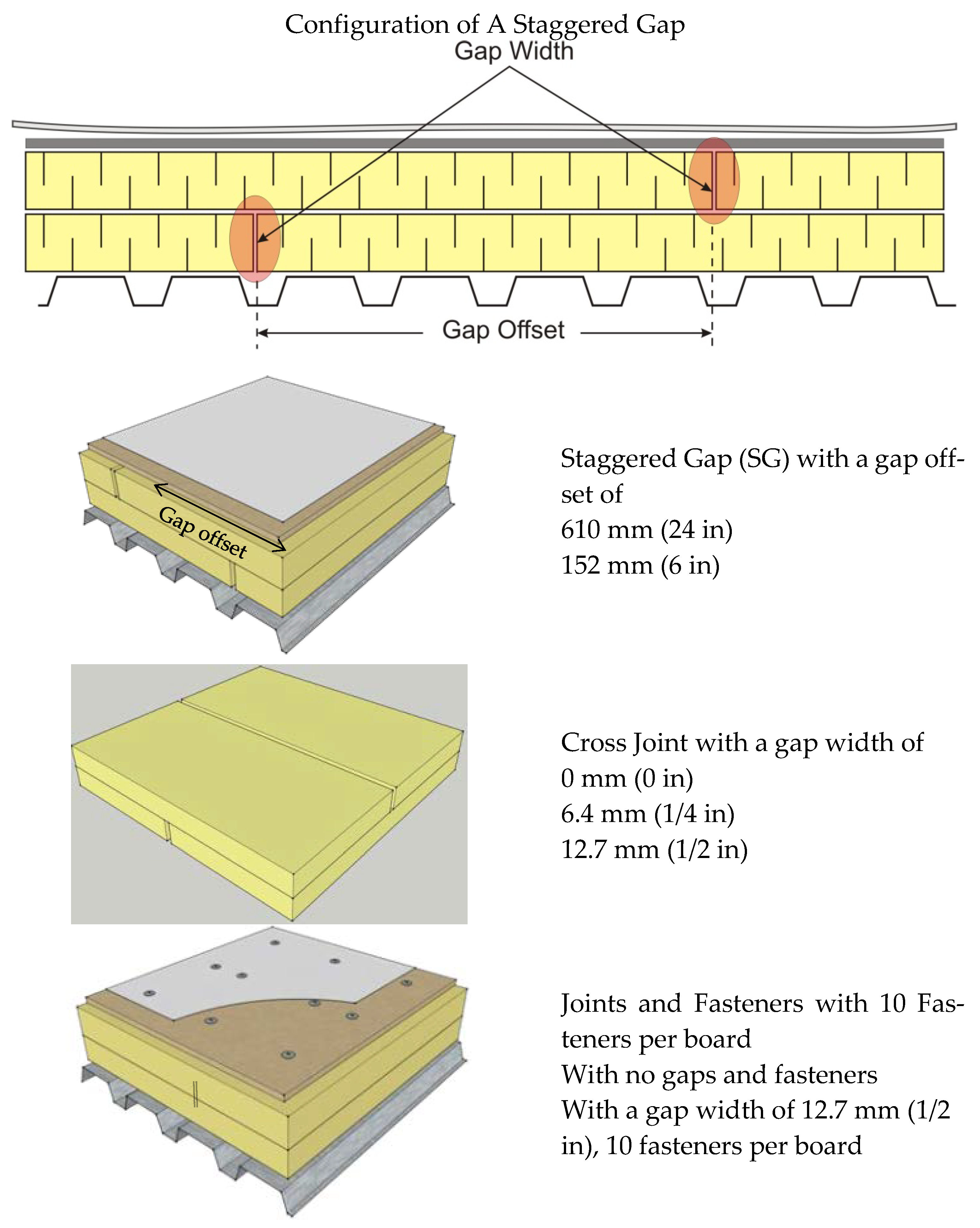
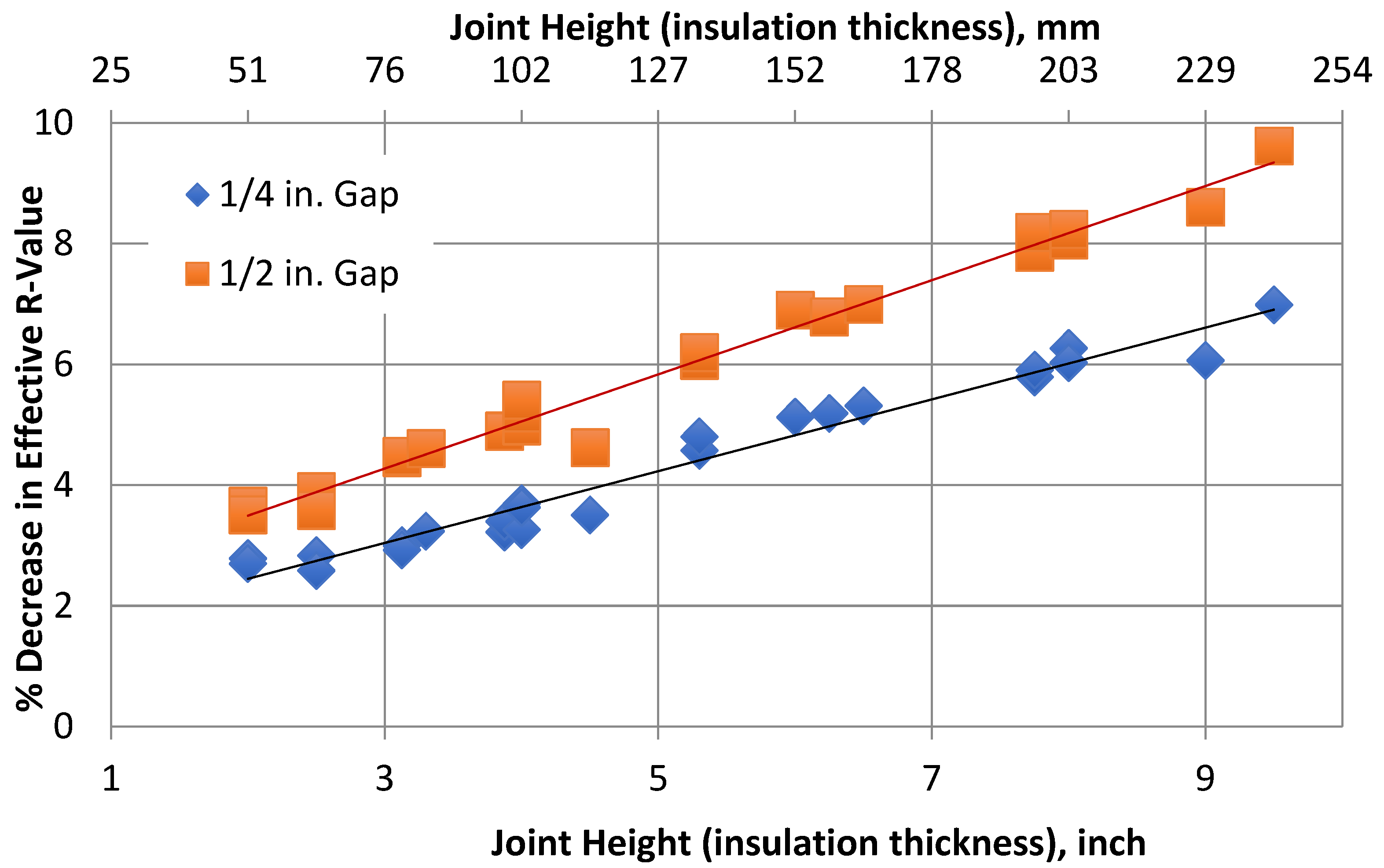
4.1.1. Gap Impact Factor

Figure 6 shows the relation between the effective R-value and the thermal bypass developed from all the roof assembly tests of R-26, R-31 and R-36. The plotted data determines the thermal losses from two gap widths by relating the joint height with the decrease in effective R-Value. It should be emphasized that the results presented here are for a standard industry practice of staggered gap arrangement of 610 mm (24 in) between the insulation boards. Moreover, this simplified data shown apply to the tested case of a single joint of 1.2 m (4 ft) length in an area of 1.49 m2 (16 ft2).
The measured data indicates a linear relationship between the assembly’s gap parameters (width and height) and thermal losses. In a two-layer staggered insulation layout, if gaps develop at the insulation joints, the data indicated that the effective R-value of the roof assembly decreases with increasing gap width and joint height or insulation thickness. For example, in a 2-layer insulation layout with the top and bottom layers 76 mm (3 in) each, a gap width of 12.7 mm (1/2 in) in the bottom layer reduces the effective R-value of the assembly by 4.2 %. If the same gap width exists in both layers, the effective R-value is lowered by 6.5%. Now, relating the gap width and the joint height to the effective R-value of the roof assembly, the measured data shows that for joint height ranging from 51 to 241 mm (2 to 9.5 in), a 6.4 mm (1/4 in) gap width lowers the thermal performance from 2.4% to 6.9% and a 1/2 in gap width leads to thermal bypass of 3.5% to 9.3%.

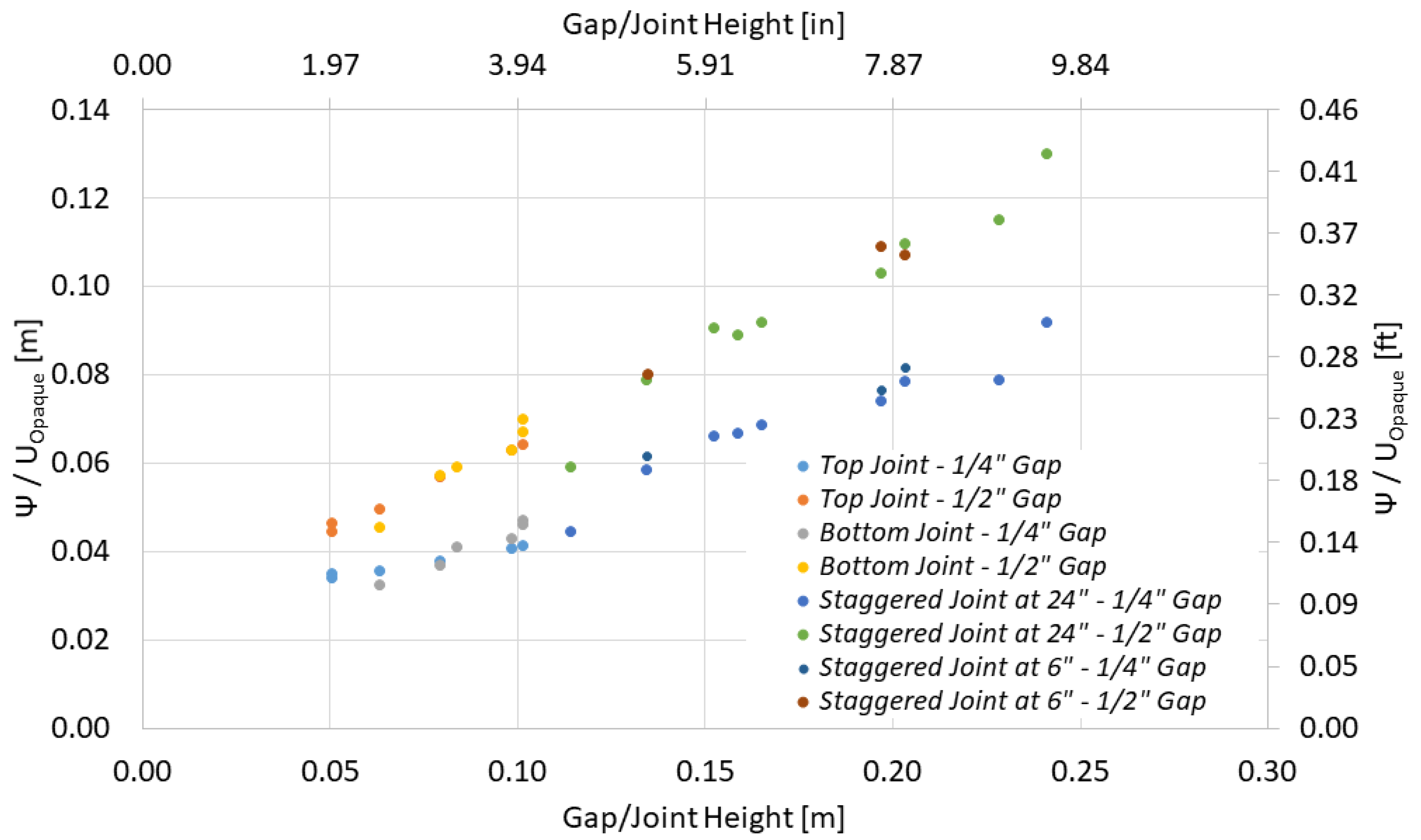
4.1.2. Impact of Joint Offset in Staggered Insulation
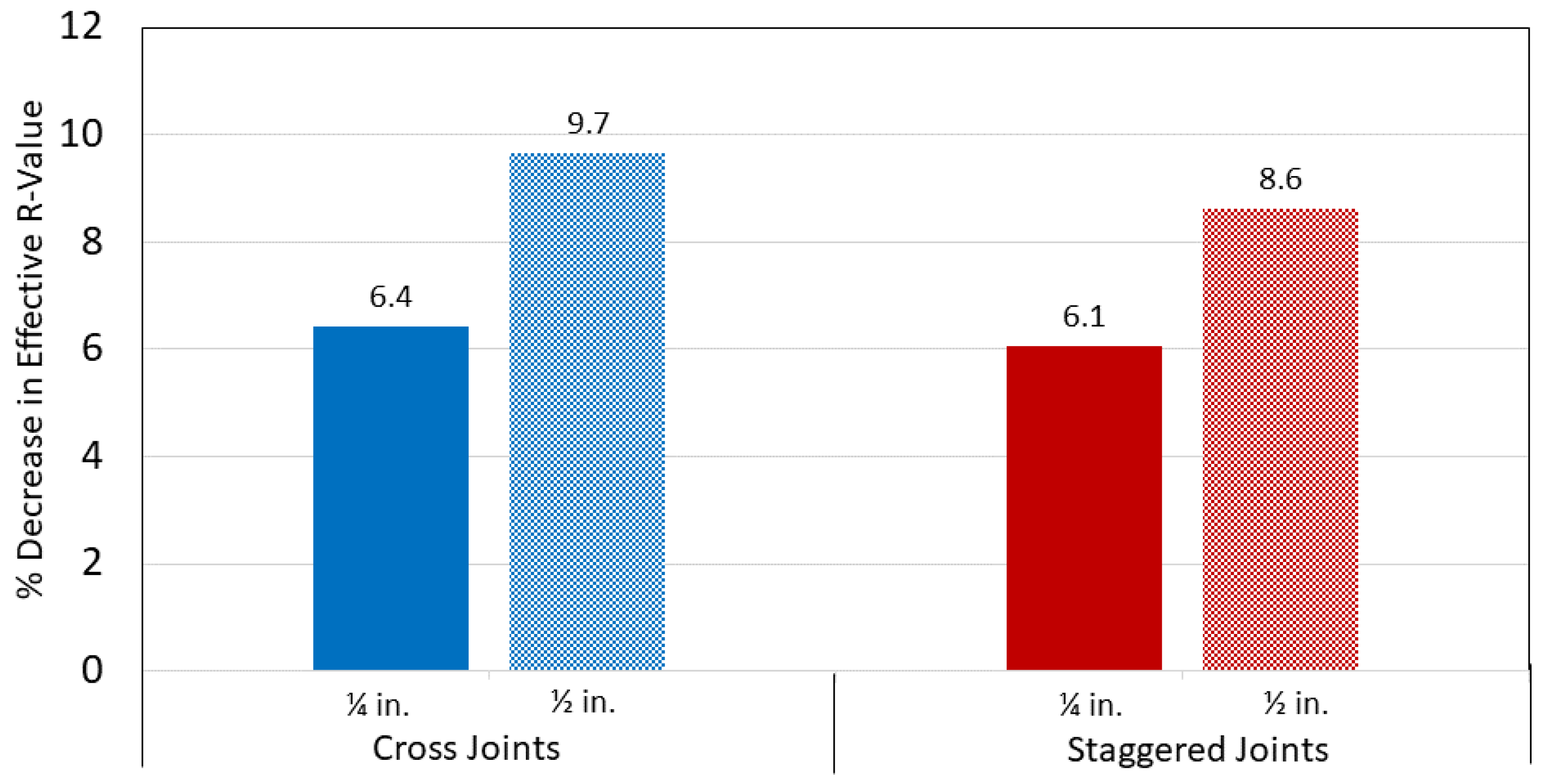
A total of 2 joint offsets, 610 mm and 152 mm (24 in and 6 in), were evaluated with the R-31 designed roof assemblies with each insulation type in its configuration. The standard industry practice of insulation joint offset in the multi-layer insulation layout is 610 mm (24 in). Therefore, the 152 mm (6 in) offset is the investigative parameter for comparing the performance relative to the 610 mm (24 in) offset.
Figure 7 shows the relation between joint offset and the overall thermal performance of the roof assembly. Irrespective of the insulation type and gap widths, the measured data showed that roof assemblies with 152 mm (6 in) joint offset showed on average 3% lower effective R-value than the 610 mm (24 in) offset. Furthermore, the data comparison for the effect of gap widths indicated a similar relationship to Figure 6, i.e., increasing gap widths lowered the overall thermal performance of the roof assembly.

4.1.3. Cross Joint

The cross joint was examined to determine if there would be a major increase in the thermal bypass. As a result, a single, albeit small, airspace going from the bottom of the insulation layers to the top was created. The testing was conducted on the EPS R-36 system with 229 mm (9 in) insulation. The results, shown in Figure 8, show the change in the effective thermal resistance of the EPS R-36 system. For the R36 EPS roofing assembly, there were a 6% and 12% increase in the percentage loss in effective R-Value for the 6.4 mm (1/4 in) and 12.7 mm (1/2 in) gaps. This indicates that the thermal losses increase due to the cross joints. To further quantify this phenomenon, further investigation is required.

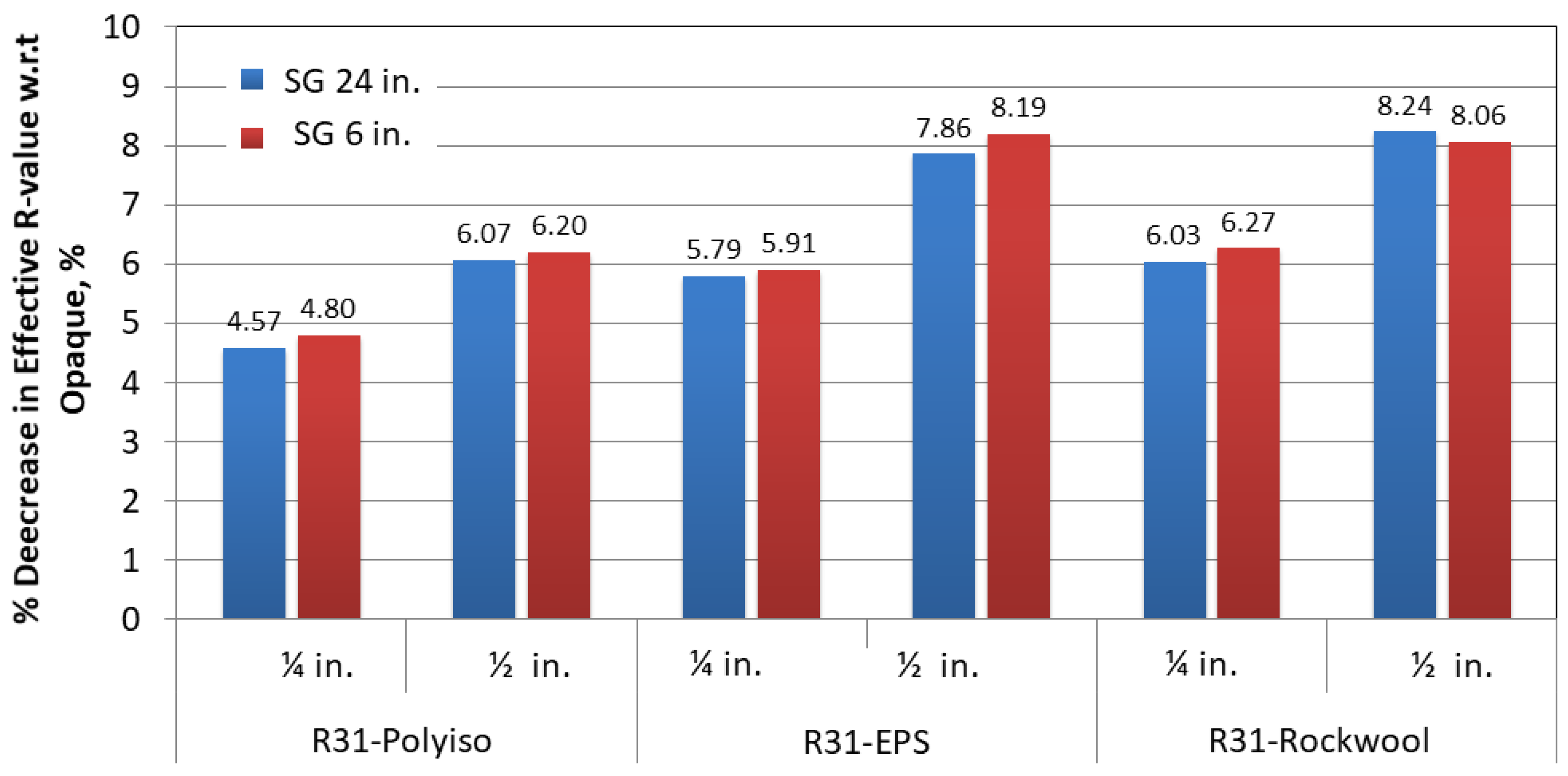
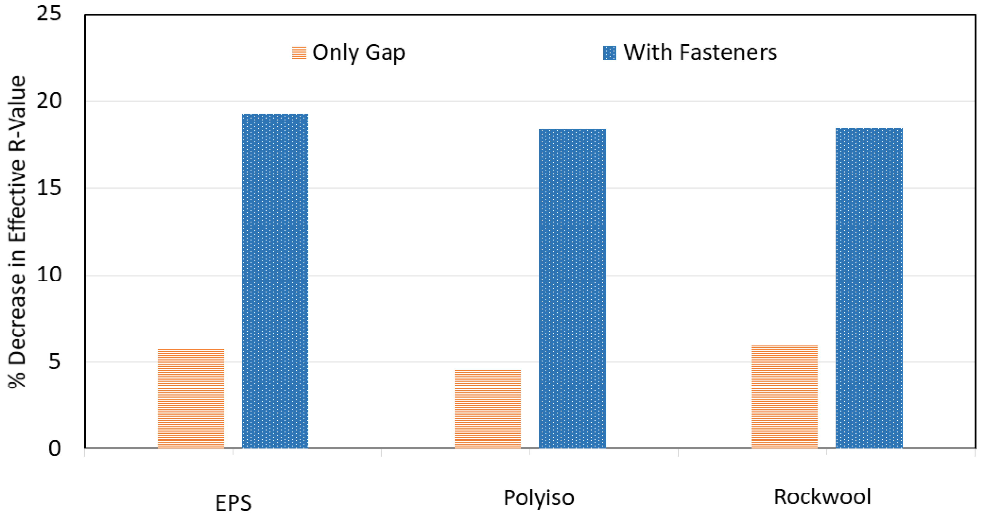
4.1.4. Joints and Fasteners

The testing on the joints and fasteners was conducted on the R31 assemblies for EPS, ISO, and Rockwool. The testing gap was maintained at 12.7 mm (1/2 in) in staggered joints at 610 mm (24 in) offset and with a fastener density of 10 fasteners per board (6.73 fasteners per m2, 0.625 fasteners per ft2). The percentage loss in R-Value is compared in Figure 9 between the case of only an insulation gap and the case of fasteners and insulation gaps. The 12.7 mm (1/2 in) gaps were responsible for 29% of the reduction in thermal resistance.

4.2. Part 2: Numerical Approach

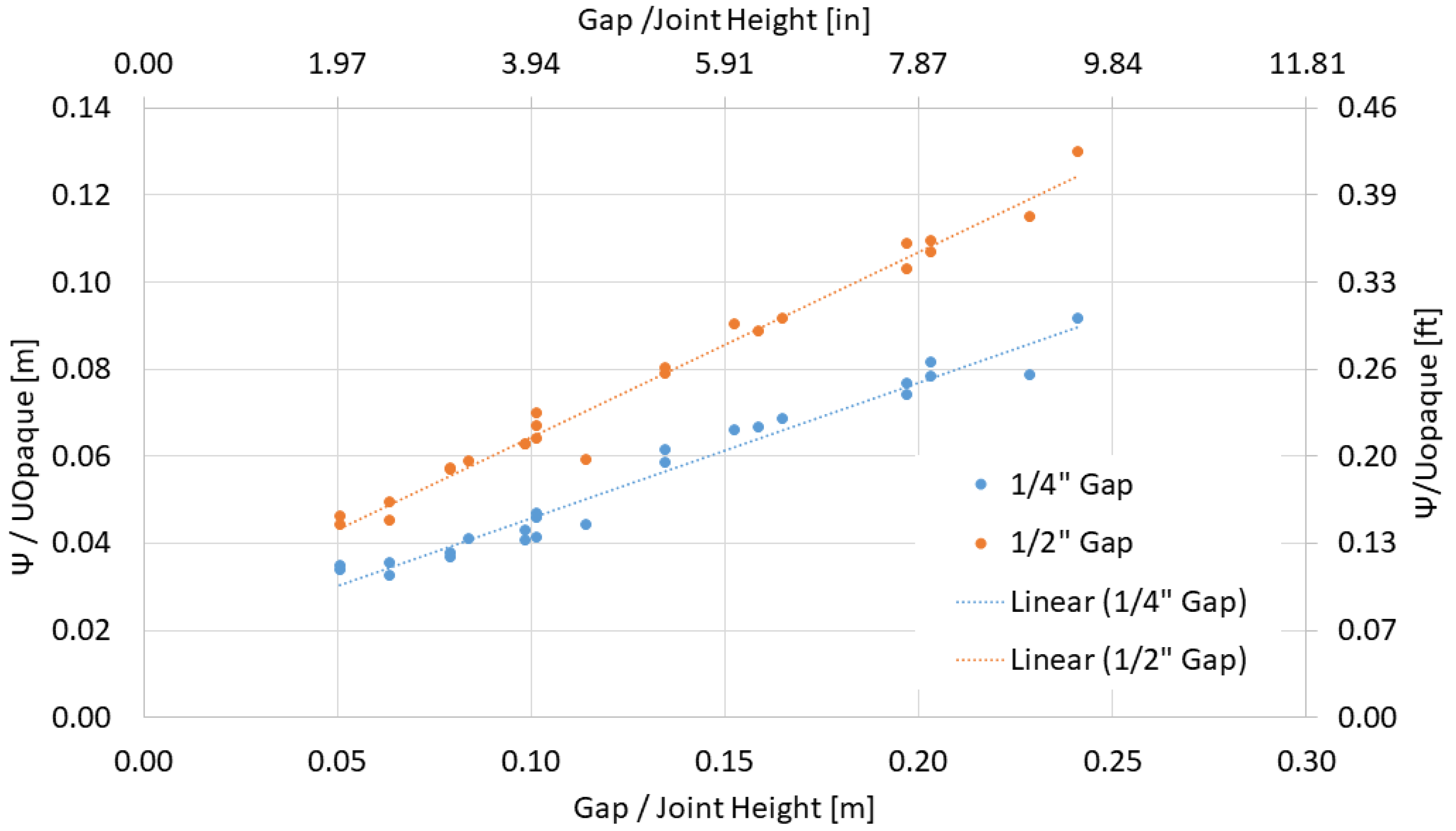
4.2.1. Psi Factor Approach

The Psi factor, as described above, was used as a means of normalizing the impact of gaps on the thermal performance of the roof assembly. As per the gap adjustment factor, the analysis of gap height and location was conducted on the systems considering the bottom, top, and the 610 mm (24 in) staggered gap [22]. In addition, the 152 mm (6 in) staggered gap configuration was also considered. To evaluate the impact of the gaps, the change in the Psi factor due to the gap in the insulation joint, Ψ , was divided by the U value of the system with no gap in the joint, Uopaque. This value was then graphed as a function of the joint height (or gap height) for all the configurations mentioned (Figure 10). The graph confirms the linear relationship between Ψ /Uopaque as a function of the Height of the Joint for all Joint Configurations.
To further normalize the results and determine the Psi factor for the joint gaps, the relationship in Equation (6) was applied to the results and graphed in Figure 11.
Based on this relationship, a linear least squares regression analysis was conducted to determine equations for the psi factor as a function of the gap height, and thermal transmittance was determined.
The relationship for the 12.7 mm (1/4 in) gap was:
Ψ = U O p a q u e · ( 0.0144 + 0.313 · h ) .   in   SI   Units Ψ = U O p a q u e · ( 0.0472 + 0.0260 · h ) .   in   I- P   Units
The relationship for the 1/2 in gap was:
Ψ = U O p a q u e · ( 0.0219 + 0.426 · h ) .   in   SI   Units Ψ = U O p a q u e · ( 0.0717 + 0.0355 · h ) .   in   I- P   Units
where h is the height of the gap, in m.
These two relationships provide a basis for determining the impact of gaps by using the Psi factor approach. This will allow users to assess the thermal bridging of staggered gaps in roofing systems with two insulation layers.
In commercial roof construction, the insulation layout around the roof drain and surrounding area has tapered insulation layers to provide the required slope to the roof assembly. The total thermal resistance varies over this tapered roof design. The thermal transmittance is usually defined by an integral over the area. The current Psi factor approach has not been evaluated to calculate the thermal transmittance of components with tapered layers. This would be a focus of future research studies.
Equations (6), (7) and (9) are used to calculate the anticipated thermal bridging and thermal bypass due to the fasteners and gaps and calculate the total change in thermal transmittance (Figure 12) of the roof assemblies. The measured data show the relative impact of the fastener and gap contribution. They also indicate a slightly higher thermal transmittance with the fasteners and gaps when tested in the guarded hot plate box than the equations. This could be due to thermal interactions between the fasteners and the gaps. However, further investigation is required to quantify this interaction further.

4.2.2. Application of Psi Factors

The following section will provie some information regarding the application of the Psi factors in terms of a general procedure for determining the thermal transmittance of a roofing system with insulation gaps specific to the 6.4 mm (1/4 in) and 12.7 mm (1/2 in) between 19 mm × 1219 mm (4 ft × 4 ft) insulation boards as well as the 1219 mm × 2438 mm (4 ft × 8 ft) insulation boards.
The procedure below provides a general application for determining the thermal bypass due to gaps within the insulation:
Step 1. Determine the Psi factor for gaps in the insulation boards based on the height of the gap using Equation (8) for each 6.4 mm (1/4 in) gap and Equation (9) for each 12.7 mm (1/2 in) gap in the roof area.
Step 2. Using Equation (5), multiply the psi factor by the length of gap length for each of the gaps, complete a summation of these values, and divide by the roof area being considered.
Step 3. Determine the corrected thermal transmittance of the roof area being considered using Equation (2).
An attempt was made to apply the Psi factors to the two sources examined in the literature review. However, in both cases [12] and [14], the exact orientation and lengths of the insulation gaps were unclear, so a direct comparison could not be made as the Psi factor could not be calculated. In addition, the width of the gaps studied was 25.4 mm (1 in). Overall, the measured loss in R-Value at the temperature of 24°C (75 °F) was 12.2% for a 10.2 cm (4 in) high staggered joint and 15.3% for a through joint of 5.1 cm (2 in) in height.

5. Summary and Conclusions

NRC developed an industry consortium project, “Energy Resistance of Commercial Roofs,” to generate codifiable data for thermal bridging and thermal bypass that would aid in the energy-efficient design of roofs. In assessing the impact of thermal bypass, more than 70 experiments were conducted highlighting the effect of staggered gaps, the gap width, through gaps, cross joints, and the impact of fasteners and gaps. The key highlights of this study are:
  • Thermal bypass increases with the gap width between insulation boards. The relative (percentage) thermal bypass also increases as the gap height increases. Overall, the average loss in effective R-value ranged from 2% to 7% and 4% to 9% for 6.4 mm (1/4 in) and 12.7 mm (1/2 in), respectively, for gap height ranging from 51 mm (2 in) to 241 mm (9.5 in). Generalized gap impact curves applicable for all three design categories-R26, R31 and R36 were developed;
  • Testing on cross joints on the EPS R-36 system having 229 mm (9 in) of insulation showed a 6% and 12% increase in the percentage loss in effective R-Value for the 6.4 mm (1/4 in) and 12.7 mm (1/2 in) gaps, respectively. This indicates an increase in the thermal losses due to the cross joints. However, to further quantify this phenomenon, further investigation is required;
  • A psi factor relationship was developed from the experimental data to support the calculation of linear thermal bypass effects on the thermal performance of the commercial roofs. These relationships provide a basis for determining the impact of gaps by using the Psi factor approach. This will allow users to assess the thermal bypass of staggered gaps and top and bottom gaps in roofing systems with two insulation layers. This testing was conducted over a range of R-values from R-26 to R-36 with 6.4 mm (1/4 in) and 12.7 mm (1/2 in) insulation gaps;
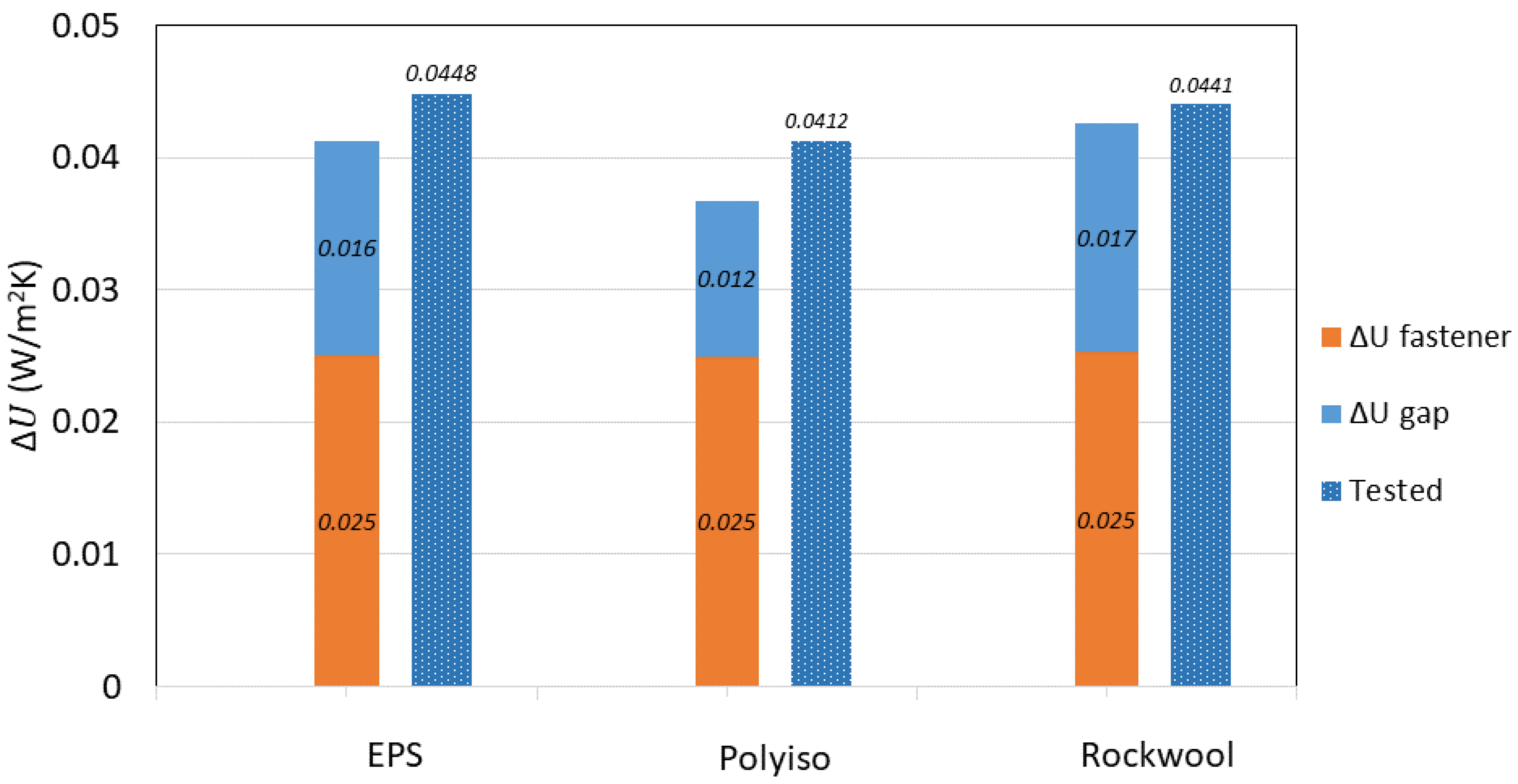
  • The psi and chi factors developed from the experimental testing were used to determine the anticipated thermal bridging and thermal bypass due to the combined fasteners and gaps and calculate the total transmittance. When comparing the test with combined fasteners and gaps, it was found that there was a higher thermal transmittance with the fasteners and gaps compared to the calculations. This could be due to thermal interactions between the fasteners and the gaps. However, further investigation is required to quantify this interaction further;
  • Based on the developed psi factors, a procedure was developed for determining the thermal transmittance due to 6.4 mm (1/4 in) and 12.7 mm (1/2 in) gaps within insulation boards in roofing systems.

Author Contributions

Conceptualization, S.M.; methodology, S.M.; formal analysis, D.v.R.; investigation, D.v.R.; resources, S.M.; data curation, S.M. and D.v.R.; writing—S.M. and D.v.R.; writing—review and editing, S.M.; supervision, S.M.; project administration, S.M.; funding acquisition, S.M. All authors have read and agreed to the published version of the manuscript.

Funding

This research received no external funding.

Institutional Review Board Statement

Not applicable.

Informed Consent Statement

Not Applicable.

Data Availability Statement

Not Applicable.

Conflicts of Interest

The authors declare no conflict of interest.

References

  1. Mukhopadhyaya, P.; Kumaran, M.K.; Ping, F.; Normandin, N. Use of vacuum insulation panel in building envelope construction: Advantages and challenges. In Proceedings of the 13th Canadian Conference on Building Science and Technology, Winnipeg, MB, Canada, 10–13 May 2011. [Google Scholar]
  2. ASHRAE 90.1; Energy Standard for Building Except Low-Rise Residential Buildings (ANSI/ASHRAE/IES Standarad 90.1). ASHRAE: Atlanta, GA, USA, 2019.
  3. ASTM Standard C518-17; Steady-State Thermal Transmission by Heat Flow Meter Apparatus. ASTM International: West Conshohocken, PA, USA, 2017.
  4. Harrje, D.T.; Dutt, G.S.; Gadsby, K.J. Convective Loop Heat Losses in Buildings. ASHRAE Trans. 1985, 91, 751–760. [Google Scholar]
  5. Chebil, S.; Galanis, N.; Zmeureanu, R. Computer Simulation of Thermal Impact of Air infiltration through Multi-layered Exterior Walls. In Proceedings of the Eighth International IBPSA Conference, Eindhoven, The Netherlands, 11–14 August 2003; pp. 155–162. [Google Scholar]
  6. Bankvall, C.; Sikander, E. Air Transport in Building Envelope and Construction Process. In Proceedings of the 8th Symposium on Building Physics in the Nordic Countries, Copenhagen, Denmark, 16–18 June 2008; Volume 3, pp. 1389–1396. [Google Scholar]
  7. Qin, M.; Belarbi, R.; Aït-Mokhtar, A.; Nilsson, L.O. Coupled heat and moisture transfer in multi-layer building materials. Constr. Build. Mater. 2009, 23, 967–975. [Google Scholar] [CrossRef]
  8. Šeduikytė, L.; Paukštys, V. Evaluation of indoor environmental conditions in offices located in buildings with large glazed areas. J. Civ. Eng. Manag. 2008, 14, 39–44. [Google Scholar] [CrossRef] [Green Version]
  9. Šadauskienė, J.; Stankevičius, V.; Bliūdžius, R.; Gailius, A. The impact of the exterior painted thin-layer render’s water va[our and liquid water permeability on the moisture state of the wall insulating system. Constr. Build. Mater. 2009, 23, 2788–2794. [Google Scholar] [CrossRef]
  10. Kosinski, P. Air thermal bridges. Tech. Trans. 2014, 3-B, 221–228. [Google Scholar]
  11. Kosinski, P. Thermal Bridge Effect of Air Gaps in Wall Construction. Tech. Sci. 2015, 18, 159–169. [Google Scholar]
  12. Lewis, J.E. Thermal Evaluation of the Effects of Gaps Between Adjacent Roof Insulation Panels. J. Therm. Insul. 1979, 3, 80–103. [Google Scholar] [CrossRef]
  13. Hedlin, C.P. Effect of insulation joints on heat loss through flat roofs. ASHRAE Trans. 1985, 91, 608–622. [Google Scholar]
  14. Petrie, T.W.; Atchley, J.A.; Desjarlais, A.O.; Christian, J.E. Effects of Mechanical Fasteners and Gaps between Insulation Boards on Thermal Performance of Low-Slope Roofs. J. Therm. Envel. Build. Sci. 2000, 23, 292–317. [Google Scholar] [CrossRef]
  15. ASTM Standard C1363-19; Standard Test Method for Thermal Performance of Building Materials and Envelop Assemblies by Means of Hot Box Apparatus. ASTM International: West Conshohocken, PA, USA, 2019.
  16. Šadauskiene, J.; Buska, A.; Burlingis, A.; Bliūdžius, R.; Gailius, A. The effect of vertical air gaps to thermal transmittance of horizontal thermal insulating layer. J. Civ. Eng. Manag. 2009, 15, 309–315. [Google Scholar] [CrossRef] [Green Version]
  17. ISO 14683:2007; Thermal Bridges in Building Construction—Linear Thermal Transmittance—Simplified Methods and Default Values. ISO: Geneva, Switzerland, 2007.
  18. International Code Council. Internation Energy Conservation Code (IECC); International Code Council: Country Club Hills, IL, USA, 2018. [Google Scholar]
  19. Canadian Commission on Building and Fire Codes. National Energy Code of Canada for Buildings; National Research Council of Canada: Ottawa, ON, Canada, 2015. [Google Scholar]
  20. Molleti, S.; Baskaran, A. Energy Resistance of Commercial Roofs; ASTM International: West Conshohocken, PA, USA, 2020; pp. 161–185. [Google Scholar] [CrossRef]
  21. Molleti, S.; van Reenen, D.; Baskaran, A. Development of chi-factors towards codification of the thermal bridging in low slope roofing assemblies. Energy Build. 2021, 231, 110559. [Google Scholar] [CrossRef]
  22. Molleti, S. Mind the gap: Thermal bypass occurs through gaps between insulation boards in low-slope roof assemblies. NRCA Prof. Roof. 2020, 50. [Google Scholar]
  23. ISO 6946:2007; Building Components and Building Elements—Thermal RESISTANCE and Thermal Transmittance—Calculation Method. ISO: Geneva, Switzerland, 2007.
Figure 1. Causes of gap formation.
Buildings 12 00068 g001
Figure 2. Typical examples of gap formations in low-slope roof assembly (Courtesy: 2001 Company & CRCA).
Buildings 12 00068 g002
Figure 3. 1.2 m × 1.2 m (4 ft × 4 ft) Guarded Hot Box (GHB).
Buildings 12 00068 g003
Figure 4. Gap Configurations.
Buildings 12 00068 g004
Figure 5. Photos of Staggered Gap Configuration.
Buildings 12 00068 g005
Figure 6. Gap Impact Factor for Top Joint, Bottom Joint, and 610 mm (24 in) Staggered Joint Configurations.
Buildings 12 00068 g006
Figure 7. Effect of Joint Offset in Staggered Joint Configuration.
Buildings 12 00068 g007
Figure 8. Cross vs. Staggered Joint: % Decrease in Effective R-Value.
Buildings 12 00068 g008
Figure 9. Decrease in Effective R-Value for R31 Systems tested with Fasteners and Gaps.
Buildings 12 00068 g009
Figure 10. Change in Ψ /Uopaque as a function of the Height of the Joint for all Joint Configurations.
Buildings 12 00068 g010
Figure 11. Psi Factor Divided by Thermal Transmittance as a Function of the Height of the Joint.
Buildings 12 00068 g011
Figure 12. Fasteners and Gaps: Comparison of the Calculated and Tested Thermal Transmittance, ΔU.
Buildings 12 00068 g012
Table 1. Design insulation nominal thickness for achieving the respective thermal resistance.
Board ThicknessR-25.21R-30.21R-35.21
Polyisocyanurate (polyiso) 51   mm + 64   mm
[2 in + 2.5 in]
51   mm + 84   mm
[2 in + 3 1/3 in]
51   mm + 102   mm
[2 in + 4 in]
Expanded Polystyrene (EPS) 80   mm + 80   mm
[3 1/8 in + 3 1/8 in]
98   mm + 98   mm
[3 7/8 in + 3 7/8 in]
117   mm + 117   mm
[4.625 in + 4.625 in]
Rockwool 64   mm + 102   mm
[2.5 in + 4 in]
102   mm + 102   mm
[4 in + 4 in]
140   mm + 102   mm
[5.5 in + 4 in]
Note: R26, R31 and R36 are effective thermal resistances that include outside and inside air films. Excluding air films, the designed thermal resistance for the roofing assemblies are R35.21, R40.21 and R46.21.
Table 2. Test Matrix for Testing on Insulation Gaps.
SystemStaggered Joints (610 mm [24”] OC)Staggered Joints (152 mm [6”] OC)Joints and Fasteners
mm [in]mm [in]mm [in]
0.0
[0]
6.4
[0.25]
12.7
[0.50]
0.0
[0]
6.4
[0.25]
12.7
[0.50]
0
[0]
12.7
[0.50]
EPSR-26
R-31
R-36
ISOR-26
R-31
R-36
SWR-26
R-31
R-36
Additional Tests
      Cross Joints—EPS R-26 System for 0, 6.4, 12.7 mm (0, 1/4 and 1/2 in)
Publisher’s Note: MDPI stays neutral with regard to jurisdictional claims in published maps and institutional affiliations.

