
Post-Earthquake Rapid Damage Assessment of Road Bridges in Glina County


Abstract
:1. Introduction
2. Theoretical and Practical Background in Bridge Assessment
2.1. Bridges Visual Inspection—Practices Overview
2.2. Bridge Seismic Assessment Methods
3. Petrinja Post-Earthquake Rapid Assessment Actions
3.1. Damage Assessment Management
3.2. Bridge Post-Earthquake Rapid Assessment Methodology
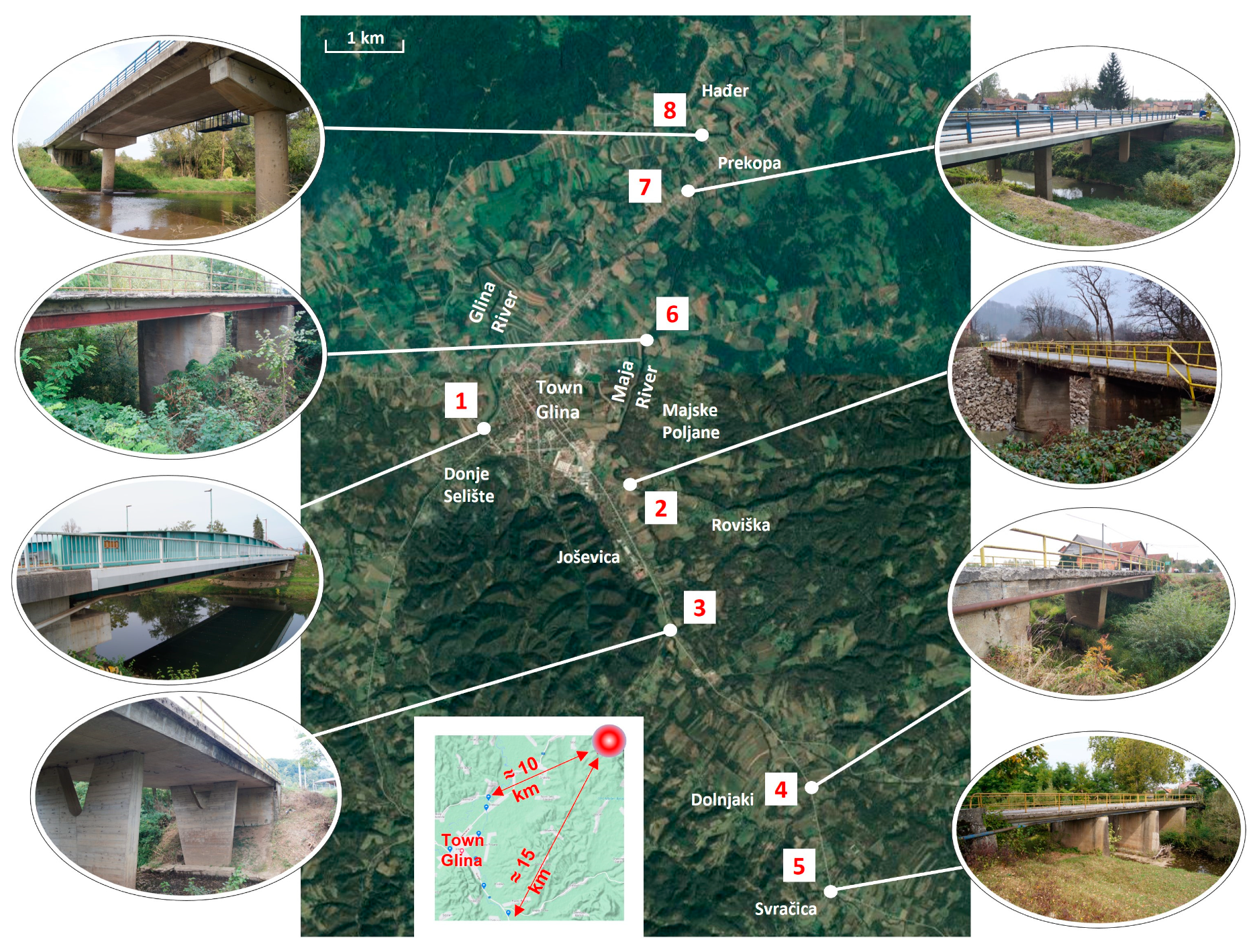
4. Glina Bridges Assessment and Damage Detection
4.1. Glina Bridge
4.2. Matija Gubec Street Bridge
4.3. Roviška Bridge
4.4. Maja Bridge
4.5. Svračica Bridge
4.6. Nikola Tesla Street Bridge
4.7. Prekopa Bridge
4.8. Hađer Bridge
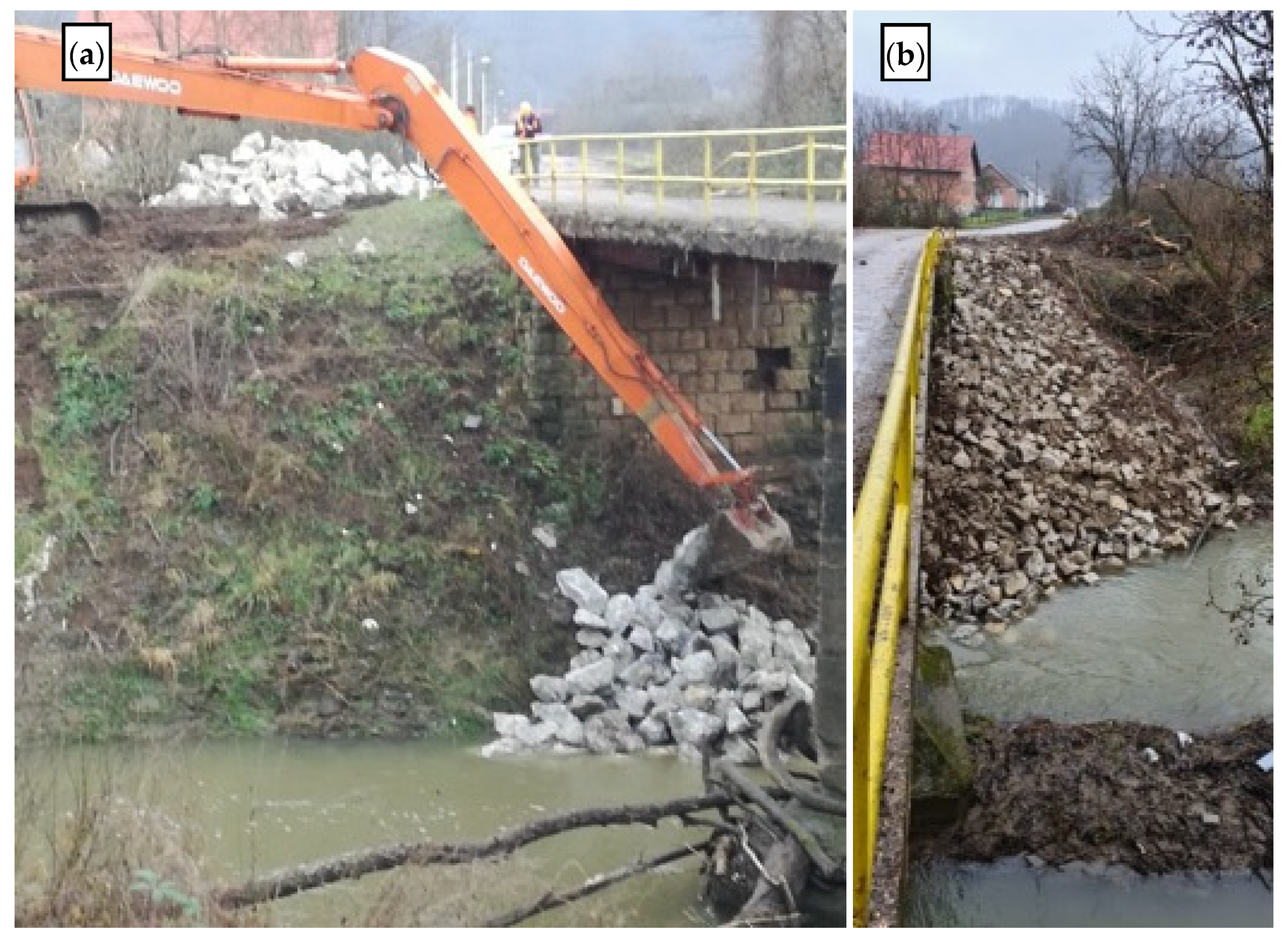
5. Immediate Strengthening Measures
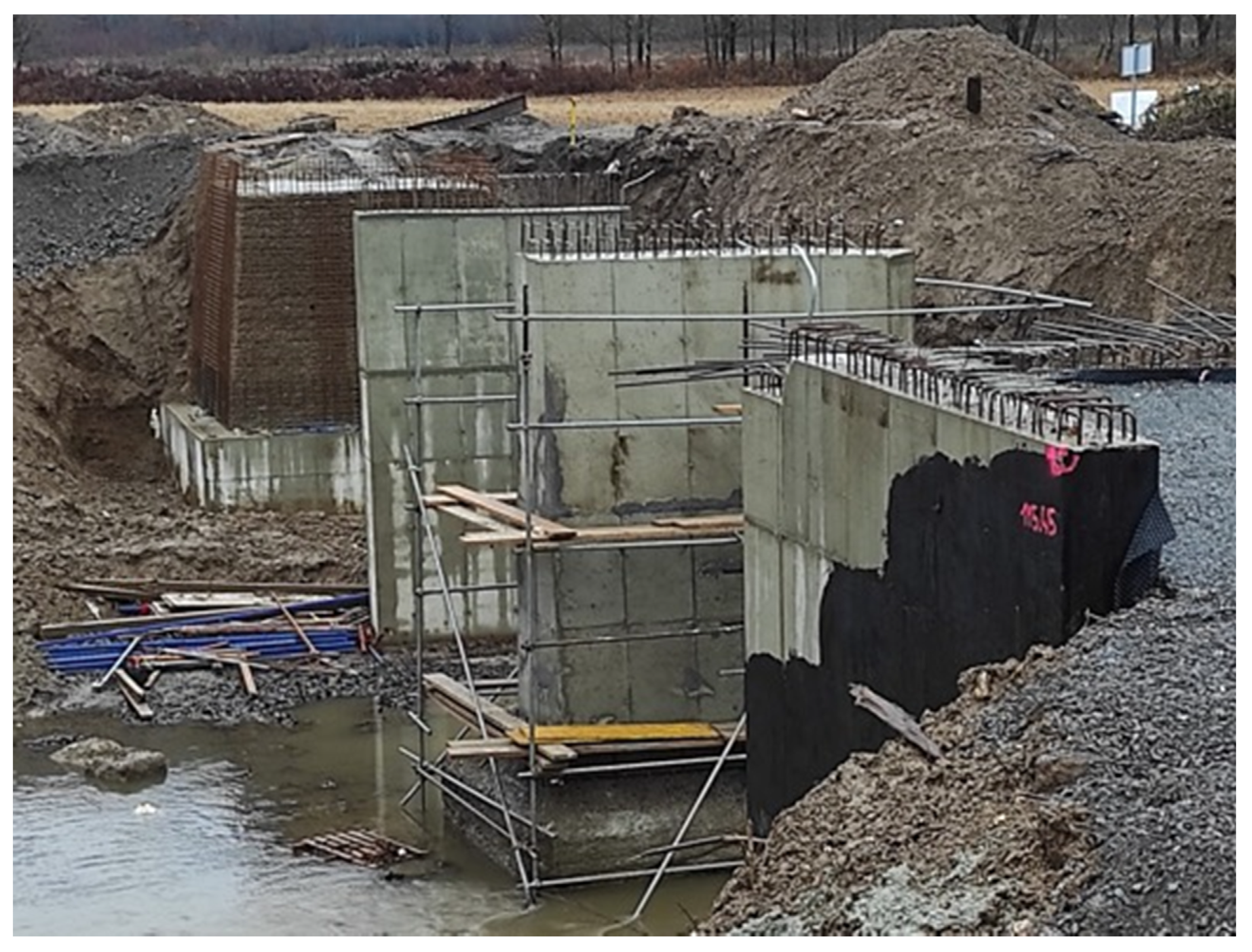
6. Recommendations for Further Rehabilitation Work and Current Progress
7. Conclusions
Author Contributions
Funding
Institutional Review Board Statement
Conflicts of Interest
References
- Government of Croatia World Bank Report. Croatia Earthquake Rapid Damage and Needs Assessment; Government of Croatia World Bank Report: Zagreb, Croatia, 2020. [Google Scholar]
- Perković, N.; Stepinac, M.; Rajčić, V.; Barbalić, J. Assessment of Timber Roof Structures before and after Earthquakes. Buildings 2021, 11, 528. [Google Scholar] [CrossRef]
- Stepinac, M.; Kisicek, T.; Renić, T.; Hafner, I.; Bedon, C. Methods for the Assessment of Critical Properties in Existing Masonry Structures under Seismic Loads-the ARES Project. Appl. Sci. 2020, 10, 1576. [Google Scholar] [CrossRef] [Green Version]
- Novak, M.Š.; Uroš, M.; Atalić, J.; Herak, M.; Demšić, M.; Baniček, M.; Lazarević, D.; Bijelić, N.; Crnogorac, M.; Todorić, M. Zagreb Earthquake of 22 March 2020—Preliminary Report on Seismologic Aspects and Damage to Buildings. Gradjevinar 2020, 72, 843–867. [Google Scholar] [CrossRef]
- Markušić, S.; Stanko, D.; Penava, D.; Ivančić, I.; Oršulić, O.B.; Korbar, T.; Sarhosis, V. Destructive M6.2 Petrinja Earthquake (Croatia) in 2020—Preliminary Multidisciplinary Research. Remote Sens. 2021, 13, 1095. [Google Scholar] [CrossRef]
- Korbar, T.; Markušić, S.; Stanko, D.; Penava, D. Petrinja M6.2 earthquake in 2020 damaged also solid linear: Are there similar active faults in Croatia? In Proceedings of the 1st Croatian Conference on Earthquake Engineering 1CroCEE, Zagreb, Croatia, 22 March 2021; Faculty of Civil Engineering, University of Zagreb: Zagreb, Croatia, 2021; pp. 353–362. [Google Scholar]
- Bacic, M.; Sasa Kovacevic, M.; Librić, L.; Žužul, P. Sinkholes induced by the Petrinja M6.2 earthquake and guidelines for their remediation. In Proceedings of the 1st Croatian Conference on Earthquake Engineering 1CroCEE, Zagreb, Croatia, 22 March 2021; Faculty of Civil Engineering, University of Zagreb: Zagreb, Croatia, 2021; pp. 341–352. [Google Scholar]
- Grünthal, G.; European Seismological Commission; Working Group “Macroseismic Scales”. European Macroseismic Scale 1998: EMS-98; European Seismological Commission, Subcommission on Engineering Seismology, Working Group Macroseismic scales: Luxembourg, 1998. [Google Scholar]
- Spence, R.; Foulser-Piggott, R. The international macroseismic scale-extending EMS-98 for global application. In Proceedings of the Second European Conference on Earthquake Engineering and Seismology, Istambul, Turkey, 25 August 2014. [Google Scholar]
- Milic, I.; Ivankovic, A.M.; Syrkov, A.; Skokandic, D. Bridge Failures, Forensic Structural Engineering and Recommendations for Design of Robust Structures. Gradjevinar 2021, 73, 717–736. [Google Scholar]
- Yokoyama, K.; Inaba, N.; Honma, A.; Ogata, N. Development of Bridge Management System for Expressway Bridges in Japan. Tech. Memo. Public Work. Res. Inst. 2006, 4009, 99–104. [Google Scholar]
- Goran Puž, A.; Radić, J.; Puž, G.; Tenžera, D. Bridge Condition Forecasting for Maintenance Optimisation. Građevinar 2013, 65, 1079–1088. [Google Scholar] [CrossRef]
- Estes, A.C.; Asce, M.; Frangopol, D.M.; Asce, F. Updating Bridge Reliability Based on Bridge Management Systems Visual Inspection Results. J. Bridge Eng. 2003, 8, 374–382. [Google Scholar] [CrossRef] [Green Version]
- Tenžera, D.; Puž, G.; Radić, J. Visual Inspection in evaluation of Bridge Condition. Gradjevinar 2012, 64, 717–726. [Google Scholar]
- Gattulli, V.; Chiaramonte, L. Condition Assesment by Visual Inspection for a Bridge Management System. Comput.-Aided Civ. Infrastruct. Eng. 2005, 20, 95–107. [Google Scholar] [CrossRef]
- Quirk, L.; Matos, J.; Murphy, J.; Pakrashi, V. Visual Inspection and Bridge Management. Struct. Infrastruct. Eng. 2018, 14, 320–332. [Google Scholar] [CrossRef]
- Graybeal, B.A.; Phares, B.M.; Rolander, D.D.; Moore, M.; Washer, G. Visual Inspection of Highway Bridges. J. Nondestruct. Eval. 2002, 21, 67–83. [Google Scholar] [CrossRef]
- Agdas, D.; Rice, J.A.; Martinez, J.R.; Lasa, I.R. Comparison of Visual Inspection and Structural-Health Monitoring as Bridge Condition Assessment Methods. J. Perform. Constr. Facil. 2016, 30, 04015049. [Google Scholar] [CrossRef] [Green Version]
- Marić, M.K.; Ivanković, A.M.; Vlašić, A.; Bleiziffer, J.; Srbić, M.; Skokandić, D. Assessment of Reinforcement Corrosion and Concrete Damage on Bridges Using Non-Destructive Testing. Gradjevinar 2019, 71, 843–862. [Google Scholar]
- Ivanković, A.M.; Skokandić, D.; Marić, M.K.; Srbić, M. Performance-Based Ranking of Existing Road Bridges. Appl. Sci. 2021, 11, 4398. [Google Scholar] [CrossRef]
- Mandić Ivanković, A.; Skokandić, D.; Žnidarič, A.; Kreslin, M. Bridge Performance Indicators Based on Traffic Load Monitoring. Struct. Infrastruct. Eng. 2019, 15, 899–911. [Google Scholar] [CrossRef]
- Skokandić, D.; Mandić Ivanković, A. Value of Additional Traffic Data in the Context of Bridge Service-Life Management. Struct. Infrastruct. Eng. 2020, 1–20. [Google Scholar] [CrossRef]
- Pelà, L.; Aprile, A.; Benedetti, A. Seismic Assessment of Masonry Arch Bridges. Eng. Struct. 2009, 31, 1777–1788. [Google Scholar] [CrossRef]
- Pelà, L.; Aprile, A.; Benedetti, A. Comparison of Seismic Assessment Procedures for Masonry Arch Bridges. Constr. Build. Mater. 2013, 38, 381–394. [Google Scholar] [CrossRef]
- Franetović, M.; Ivanković, A.M.; Radić, J. Seismic Assessment of Existing Reinforced-Concrete Arch Bridges. Gradjevinar 2014, 66, 691–703. [Google Scholar] [CrossRef] [Green Version]
- Monteiro, R.; Delgado, R.; Pinho, R. Probabilistic Seismic Assessment of RC Bridges: Part I—Uncertainty Models. Structures 2016, 5, 258–273. [Google Scholar] [CrossRef]
- Monteiro, R. Sampling Based Numerical Seismic Assessment of Continuous Span RC Bridges. Eng. Struct. 2016, 118, 407–420. [Google Scholar] [CrossRef]
- Cassese, P.; de Risi, M.T.; Verderame, G.M. Seismic Assessment of Existing Hollow Circular Reinforced Concrete Bridge Piers. J. Earthq. Eng. 2020, 24, 1566–1601. [Google Scholar] [CrossRef]
- Srbić, M.; Ivanković, A.M.; Vlašić, A.; Kovačević, G.H. Plastic Joints in Bridge Columns of Atypical Cross-sections with Smooth Reinforcement without Seismic Details. Appl. Sci. 2021, 11, 2658. [Google Scholar] [CrossRef]
- Homaei, F.; Yazdani, M. The Probabilistic Seismic Assessment of Aged Concrete Arch Bridges: The Role of Soil-Structure Interaction. Structures 2020, 28, 894–904. [Google Scholar] [CrossRef]
- Zelaschi, C.; Monteiro, R.; Pinho, R. Parametric Characterization of RC Bridges for Seismic Assessment Purposes. Structures 2016, 7, 14–24. [Google Scholar] [CrossRef]
- Morbin, R.; Zanini, M.A.; Pellegrino, C.; Zhang, H.; Modena, C. A Probabilistic Strategy for Seismic Assessment and FRP Retrofitting of Existing Bridges. Bull. Earthq. Eng. 2015, 13, 2411–2428. [Google Scholar] [CrossRef]
- Stepinac, M.; Lourenço, P.B.; Atalić, J.; Kišiček, T.; Uroš, M.; Baniček, M.; Šavor Novak, M. Damage Classification of Residential Buildings in Historical Downtown after the ML5.5 Earthquake in Zagreb, Croatia in 2020. Int. J. Disaster Risk Reduct. 2021, 56, 102140. [Google Scholar] [CrossRef]
- Lulić, L.; Ožić, K.; Kišiček, T.; Hafner, I.; Stepinac, M. Post-Earthquake Damage Assessment-Case Study of the Educational Building after the Zagreb Earthquake. Sustainability 2021, 13, 6353. [Google Scholar] [CrossRef]
- Baggio, C.; Bernardini, A.; Colozza, R.; Pinto, A.; Taucer, F. Field Manual for Post-Earthquake Damage and Safety Assessment and Short Term Countermeasures (AeDES); Translation from Italian: Maria ROTA and Agostino GORETTI; European Commission: Luxembourg, 2007. [Google Scholar]
- Setunge, S.; Li, C.Q.; Mcevoy, D.; Zhang, K.; Mullett, J.; Mohseni, H.; Mendis, P.; Ngo, T.; Herath, N.; Karunasena, K.; et al. Failure Mechanisms of Bridge Structures under Natural Hazards; RMIT: Melbourne, Australia, 2018. [Google Scholar]
- Tanimura, S.; Sato, T.; Umeda, T.; Mimura, K.; Yoshikawa, O. A Note on Dynamic Fracture of the Bridge Bearing Due to the Great Hanshin-Awaji Earthquake. Int. J. Impact Eng. 2002, 27, 153–160. [Google Scholar] [CrossRef]
- Mitchell, D.; Huffman, S.; Tremblay, R.; Saatcioglu, M.; Palermo, D.; Tinawi, R.; Lau, D. Damage to Bridges Due to the 27 February 2010 Chile Earthquake. Can. J. Civ. Eng. 2013, 40, 675–692. [Google Scholar] [CrossRef]
- Kawashima, K.; Buckle, I. Structural Performance of Bridges in the Tohoku-Oki Earthquake. Earthq. Spectra 2013, 29, 315–338. [Google Scholar] [CrossRef]
- Hajdin, R.; Kušar, M.; Mašović, S.; Linneberg, P.; Amado, J.; Tanasić, N. COST Action TU1406: Quality Specifications for Roadway Bridges, Standardization at a European Level; WG3 Technical Report: Establishment of a Quality Control Plan; COST: Brussels, Belgium, 2018. [Google Scholar]


| Bridge | Seismic Damage | Degradation | Design Flaws |
|---|---|---|---|
| Glina bridge | No damage | Expansion joints clogged, steel corrosion | Not evident |
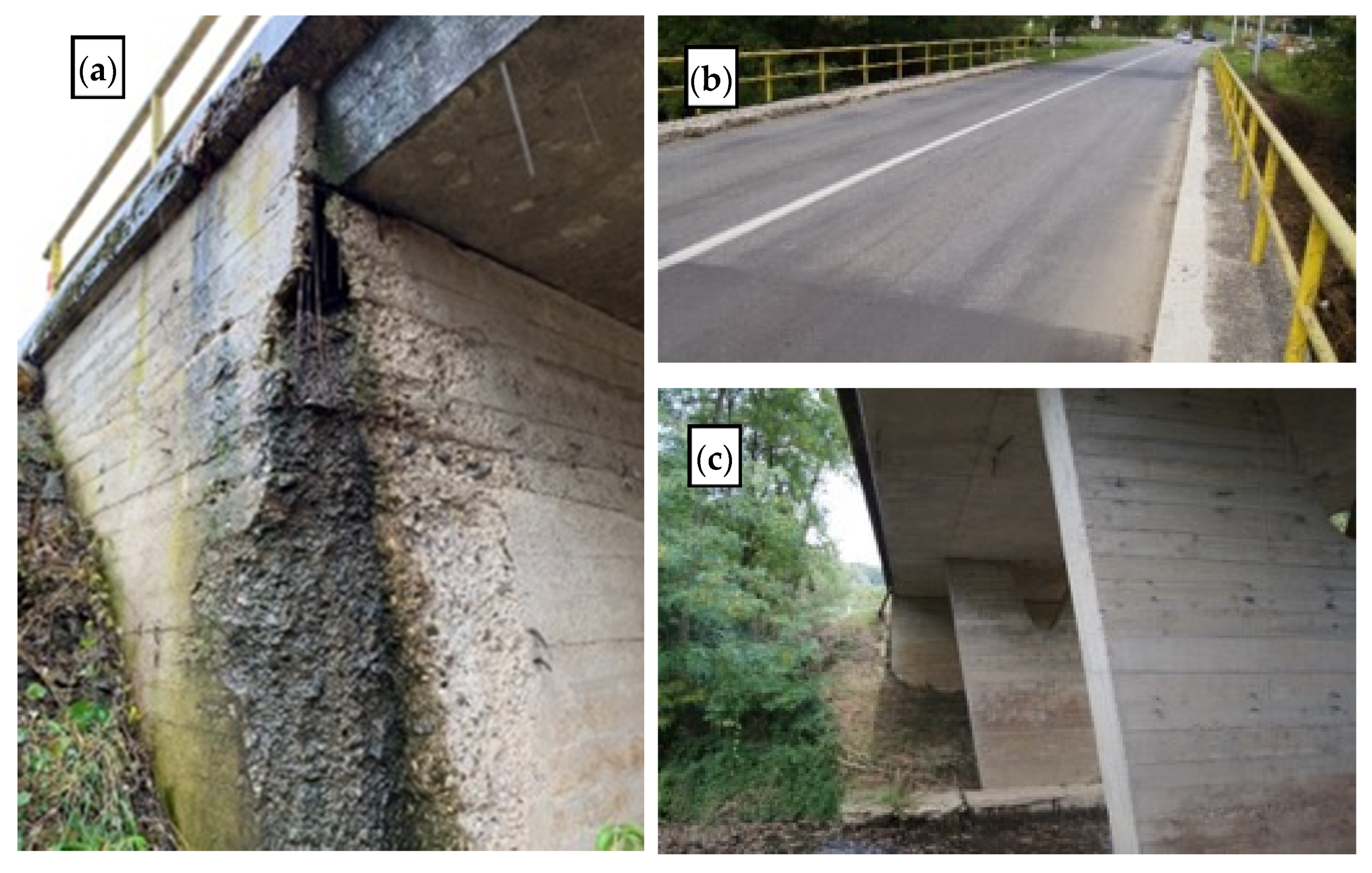
| Matija Gubec Street bridge | Abutment sliding and block wall damage | Heavy steel corrosion, concrete spalling and reinforcement corrosion, scour, footways and cornice partly missing | Insufficient foundation for one column, one abutment from stone blocks and one from reinforced concrete, no waterproofing and drainage |
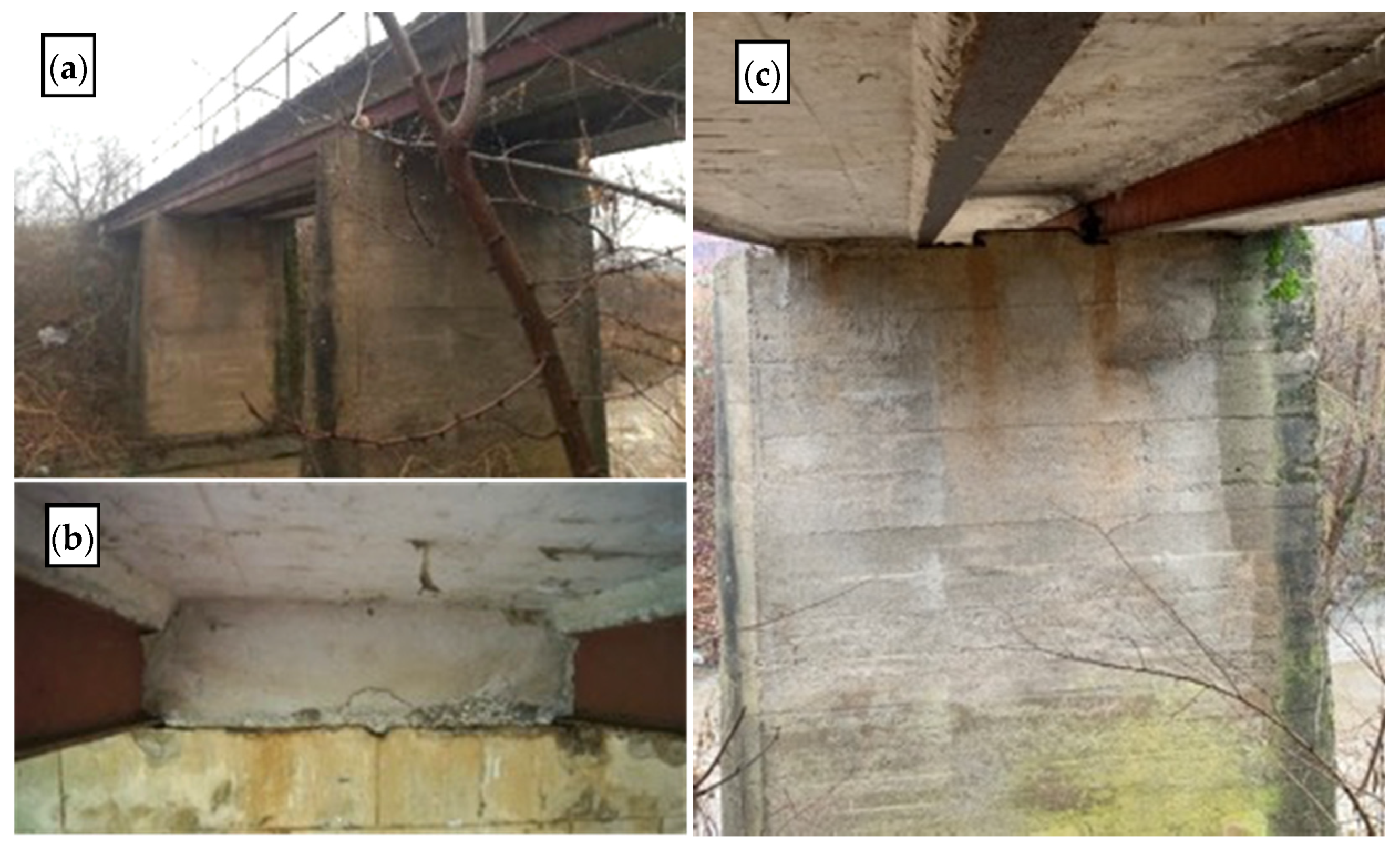
| Roviška bridge | No damage | Abutment wall reinforcement corrosion, parts of side wall missing, heavily degraded footway and cornice, possible column foundation scour | Abutment side wall with insufficient reinforcement and poor concrete, no waterproofing and drainage |
| Maja bridge | No damage | Clogged drainage, heavily degraded footway, abutments exposed to water damage | Poor waterproofing, dilatation between abutment wall and wings |
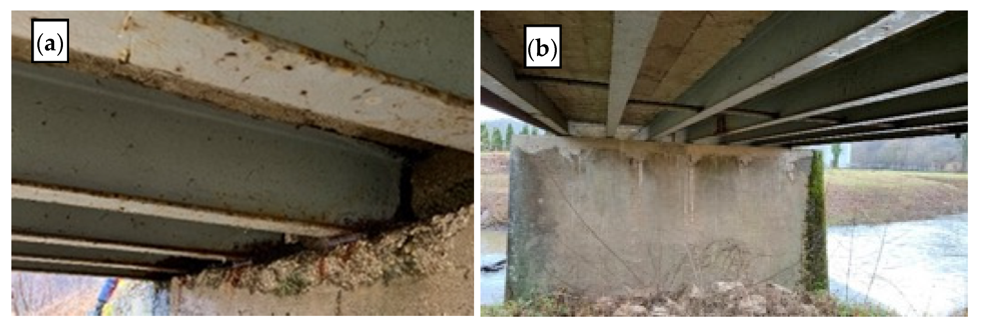
| Svračica bridge | No damage | Steel girder corrosion, columns reinforcement corrosion | No waterproofing or drainage |
| Nikola Tesla Street bridge | No damage | Steel girder corrosion, columns reinforcement corrosion, heavily degraded footway and cornice, heavy asphalt damage | No waterproofing or drainage |
| Prekopa bridge | No damage | Expansion joint clogged and with failed waterproofing, abutment wall water leakage | Not evident |
| Hađer bridge | Excessive movements, abutment wall damage, asphalt damage, cornice damage | Heavy water leakage on abutment walls and column head, concrete spalling and reinforcement corrosion, cracked column head | No expansion joints, no bearings, no drainage, girders not symmetrically supported |
Publisher’s Note: MDPI stays neutral with regard to jurisdictional claims in published maps and institutional affiliations. |
© 2022 by the authors. Licensee MDPI, Basel, Switzerland. This article is an open access article distributed under the terms and conditions of the Creative Commons Attribution (CC BY) license (https://creativecommons.org/licenses/by/4.0/).
Share and Cite
Vlašić, A.; Srbić, M.; Skokandić, D.; Mandić Ivanković, A. Post-Earthquake Rapid Damage Assessment of Road Bridges in Glina County. Buildings 2022, 12, 42. https://doi.org/10.3390/buildings12010042
Vlašić A, Srbić M, Skokandić D, Mandić Ivanković A. Post-Earthquake Rapid Damage Assessment of Road Bridges in Glina County. Buildings. 2022; 12(1):42. https://doi.org/10.3390/buildings12010042
Chicago/Turabian StyleVlašić, Anđelko, Mladen Srbić, Dominik Skokandić, and Ana Mandić Ivanković. 2022. "Post-Earthquake Rapid Damage Assessment of Road Bridges in Glina County" Buildings 12, no. 1: 42. https://doi.org/10.3390/buildings12010042