Article

Assessment of the Seismic Behavior of a Precast Reinforced Concrete Industrial Building with the Presence of Horizontal Cladding Panels

1
RISCO, Civil Engineering Department, University of Aveiro, 3810-193 Aveiro, Portugal
2
CDRSP, ESTG-Polytechnic of Leiria, 2411-901 Leiria, Portugal
3
CERIS, Civil Engineering Department, ESTG-Polytechnic of Leiria, 2411-901 Leiria, Portugal
*
Author to whom correspondence should be addressed.
Buildings 2021, 11(9), 400; https://doi.org/10.3390/buildings11090400
Submission received: 26 July 2021 / Revised: 23 August 2021 / Accepted: 26 August 2021 / Published: 7 September 2021
(This article belongs to the Collection Structural Analysis for Earthquake-Resistant Design of Buildings)

Abstract

:
The latest earthquakes in Europe exposed some critical problems in the connections of cladding panels in industrial precast reinforced concrete (PRC) structures. These connections did not perform as desired, causing the panels to fall, leading to significant nonstructural damage that resulted in the loss of human life and significant socio-economic impacts due to the interruption of business. Furthermore, in addition to the behavior of the cladding system itself, it is still not clear to what extent it can influence the overall seismic performance of the main structure. Making use of a simplified macroelement, the present study assesses the seismic performance of commonly employed cladding-to-structure connections, as well as the interaction of cladding panels with industrial PRC buildings. The analyses were carried out considering a PRC building representative of a Portuguese industrial park, studied with and without cladding panels. The seismic behavior of the structure was assessed considering both nonlinear static and dynamic procedures.

1. Introduction

In Europe, industrial precast reinforced concrete (PRC) buildings represent a significant part of the industrial building stock [1,2]. Recent earthquakes have exposed the main vulnerabilities of PRC buildings, highlighting both structural and nonstructural damage, mostly related to the deficient transfer of horizontal loads at the connections between elements [1]. The inadequate design of these connections may have caused the cladding panels (with weights of up to 10 tons) to collapse, representing a potential risk for humans, even during evacuation procedures [3], as well as significant economic losses [4].
The recent earthquakes in Italy, such as L’Aquila in 2009 and Emilia in 2012, highlighted some critical issues associated with the behavior of the cladding-to-structure devices utilized in the past [5]. It was observed that the different cladding-to-structure fastenings play key roles in the safety, performance, and the economics of both the cladding system as well as the main structure itself. Several authors reported heavy damage related to cladding panels [4,6,7,8]. In particular, Bournas et al. [9] reported that approximately 75% of industrial PRC buildings designed without seismic provisions exhibited damage and detachment of the exterior cladding panels, as shown in Figure 1a.
The undesirable behavior and contribution of the cladding panels to the seismic response of buildings occur due to the high stiffness of the panels when compared with the stiffness of the connections, and because these connections are not ductile enough to accommodate the displacement demand imposed by the structure [10].
The current design practice for industrial PRC buildings is based on bare-frame models and the cladding-panel contribution is generally neglected; therefore, no interaction between the panels and the structure is considered [1]. Furthermore, it was observed in a recent survey carried out on Portuguese PRC buildings [11] that cladding panels, both in old and recent buildings, are generally not considered in the design, not even with simplified procedures, ignoring the interaction with the frame and it is considered that they do not contribute to seismic behavior. Several authors, however, have demonstrated that cladding panels can have a significant contribution to the seismic response [1,4,12,13,14,15,16].
In a Portuguese industrial park, the most current arrangement of observed cladding panels is the horizontal one (Figure 2), which has been identified by several authors ([10,17,18]) as the most vulnerable arrangement, based on the damage observed from recent earthquakes. Typically, the connection to the masin structure is ensured through mechanical connections that are designed to support forces that are orthogonal to the plane of the panels. As shown by [1,13,14], this approach may lead the panels to became part of the resistance system, attracting higher seismic forces than those calculated based on a bare frame model, causing the fastening elements to fail (Figure 1b).
Considering that the connection between the cladding panels and the main structure was one of the least investigated issues in PRC [18], the project Safecladding, emerged to give answers to the problems previously mentioned, aiming to improve the conception and design of new fastening systems to guarantee good seismic performance of the panels and the structure itself [15]. Nonetheless, the deficient connection of the existing panels is not sufficiently covered in the existing literature nor by the industry [3].
Taking into consideration the previous issues, this study analyzes the capacity of commonly employed cladding panels, as well as their importance in the seismic response of PRC considering a building representative of the Portuguese industrial park. The contribution of the panels might be particularly relevant in the seismic performance considering the high flexibility and low horizontal strength found in these building by Sousa et al. [19]. The seismic performance, assessed with nonlinear static and dynamic analyses, is analyzed considering models with and without cladding panels, simulated through a simplified macroelement representative of the cladding-to-structure connections commonly used. This novel model was calibrated based on experimental tests and can be easily applied in future simulation in different software platforms. Finally, the results of the analysis and seismic assessment were carried out as a function of force, displacement, and dissipated energy.

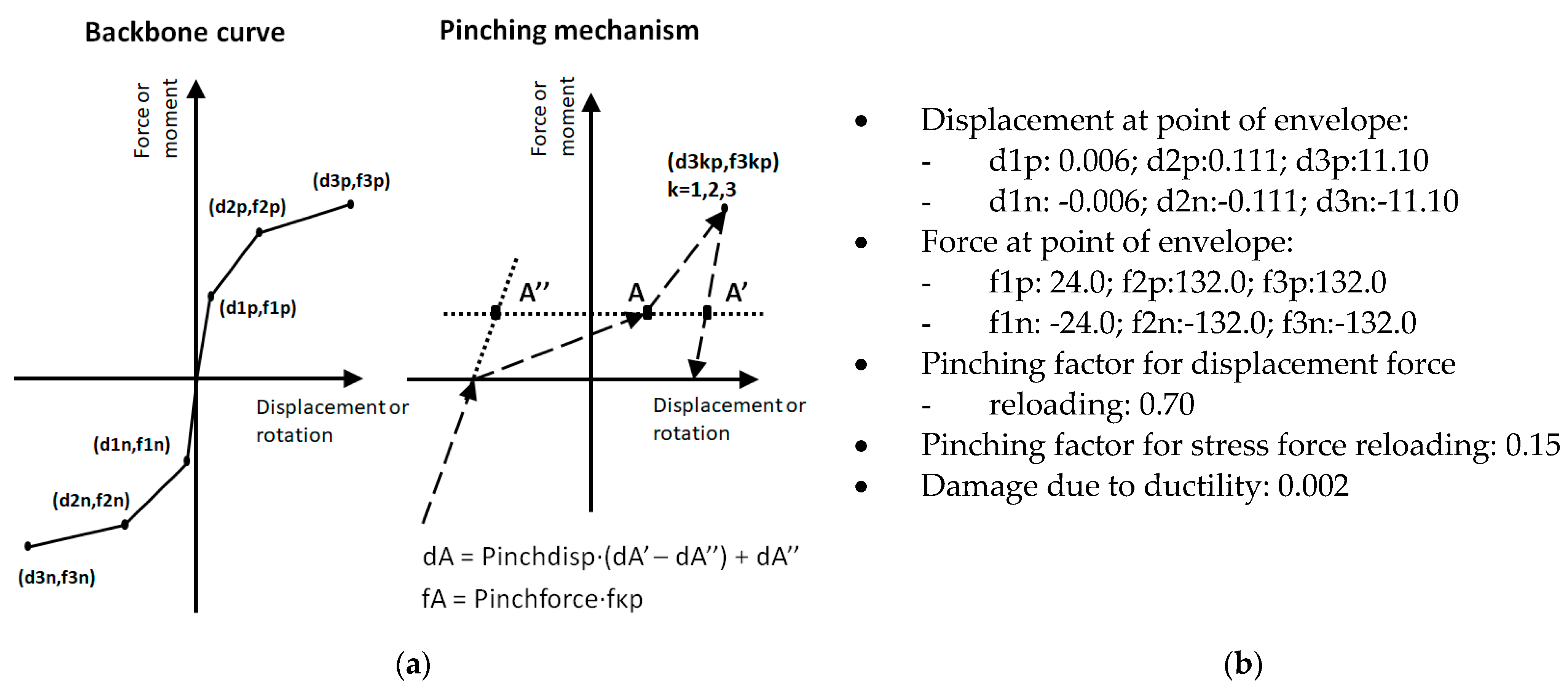
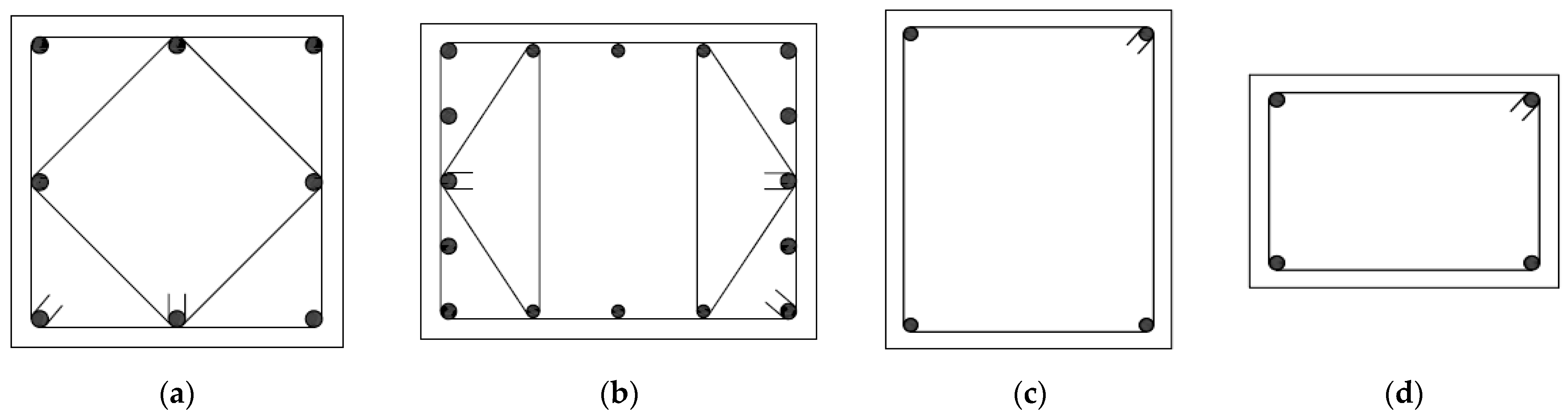
2. Numerical Modelling of Cladding Panels

Precast reinforced concrete industrial buildings are structures with significantly more flexibility when compared with traditional RC residential building, due to the higher story height (in Portugal the typically story height is between 6 and 8 m [11]) and the column boundary condition, usually materialized through cantilever columns fixed at the base with prestressed beams with hinged connections between these two elements.
The way to model the contribution of the cladding panels in the PRC building has suffered several improvements in the last years [17,20], from elastic elements mixed with rigid bars to include the initial stiffness, to multiple struts and springs to include the mass and nonlinear behavior of the connections [21], among other strategies. Belleri et al. [3] presented a numerical model of horizontal panels, with elastic beams connected to the columns by means of nonlinear springs. The panel mass is directly included in the model by assigning a mass density to the corresponding beam element and the columns are fixed at the base and modelled with nonlinear fibre elements. This strategy aims to represent each panel that constitutes the façade wall, and each connection is simulated by a nonlinear spring. Alternatively, Starešinič et al. [22] formulated a more detail numerical macro-model, capable of simulating the response of the connections combining different material models. Although these solutions seem to produce reliable results, their relative complexity inhibits their generalized application by engineer practitioners.

Simplified Macroelement

The present work proposes a modelling strategy inspired by the simplified model developed for infill masonry walls by [23], that consists of a simplified macroelement aiming to simulate the contribution of a conventional horizontal cladding system (panels and associated connections) to the main PRC structure.
In this PRC cladding panel model, the contribution of all the horizontal panels within a frame is concentrated in one macroelement defined at the centre of the frame and connected to the column’s edges through four diagonal truss elements, with a rigid behavior. Figure 3 illustrates the concept by showing the hysteretic behavior assumed for a single connection (left) and that would be expected if one includes the contribution of all the 12 connections (four per panel) within the frame. With this arrangement, the nonlinear hysteretic behavior resulting from the contribution of all the panels and associated connections is concentrated in the central element, whose behavior reflects the lateral resisting force as a function of the relative horizontal displacement measured between the top and the bottom of the columns. Differently from the models presented by Belleri et al. [3] and Starešinič et al. [22] that simulate different connections at the top and bottom of the cladding panel, in this model the central element concentrates the contribution of all the connections. The main advantage of the proposed model relies on its simplicity, when compared with other existing strategies, avoiding the need for the column’s intermediate nodes.
The hysteretic response of the central element encompasses the contribution of all the connections in a given frame and was calibrated based on the experimental tests conducted on a “Standard” connection by Del Monte et al. [5], whose results and calibration for two connections are presented in Figure 4. This choice was based on the similarities of this connection with the commercial solution typically used in Portugal (Figure 2b), referring to the isostatic sliding-frame system for horizontal panels consisting of an anchor channel installed with hammerhead screws. The incorporation of the experimental test results in the numerical model was carried out through the pinched asymmetric model, available in SeismoStruct [24], which managed to adequately fit the cyclic hysteretic behavior described in the work of Del Monte et al. [5] in terms of force−deformation and energy dissipation. The backbone curve of this model is defined by a trilinear relationship, associated with each direction along the panel’s plane, whilst five additional parameters allow for the adjustment of the unloading/reloading curves and the strength degradation. The model parameters were adjusted to minimize the difference between the experimental result and the numerical result obtained in the simulation of the same test. The proposed model parameters are identified in Figure 5.
Considering that numerical spring includes the contribution of all the connections within the frame, the force and displacements assigned to each reference point of the trilinear relation ( F m a c r o and δ m a c r o ) should be determined based on the following Equations (1) and (2):
F m a c r o = F 1 × N p   × N c
δ m a c r o = δ 1 × N p × 2
In the previous equations, F1 and δ1 refer to the forces and displacements corresponding to a single connection only, i.e., the force and displacement values proposed in Figure 5. To obtain the force and displacement capacity of all the panels in a frame, these should be multiplied by the number of panels (NP) and the number of connections per panel (NC). These equations assume that the panels remain undeformable in their own plane and that each connection has an equal contribution in terms of force and deformation capacity.

3. Description of Seismic Analysis
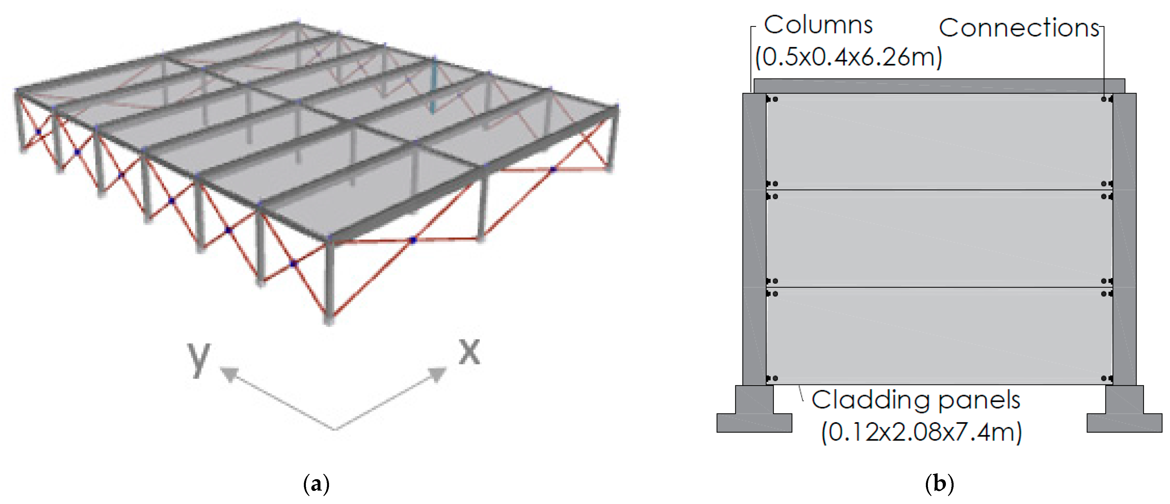
3.1. Case Study

The case study refers to an existing PRC industrial building, located in Portugal in the seismic zone 1.5, characterized by a reference peak ground acceleration of 0.06 g, for a return period of 475 years and a soil type B, according with the seismic zonation defined in the Portuguese version of the Eurocode 8–Part 1 [25]. The building under study is a framed structure (Figure 6) consisting of one floor with a height of 6.26 m and an area of 39.32 × 44.8 m2. The structure has two spans in the X direction with 18.12 m and 21.2 m and six spans in the Y direction with 7.4 m (edge spans) and 7.5 m (inner spans). The columns, assumed fixed to the foundation, have a height of 6.26 m and two different cross-sections: a 0.4 × 0.4 m2 section at the central columns and 0.5 × 0.4 m2 in the remaining ones (Figure 7). The building features two types of precast prestressed beams: the longitudinal beams with a cross section of 0.5 × 0.4 m2, and the transversal beams with a cross section of 0.4 × 0.3 m2. The concrete used was from the class C40/50 and the steel from the class S500 NR-SD.

3.2. Numerical Analyses

The structural analyses were carried out along the two main directions with a 3D model using the computer program SeismoStruct [24], a finite elements package capable of predicting the large displacement behavior of space frames under static or dynamic loading, taking into account both geometric nonlinearities and material inelasticity. In the model developed, the columns were modelled with fibre-based nonlinear force-based elements with five integration points, following the recommendations of Sousa et al. [26], whilst an elastic behavior was assumed for both longitudinal and transverse beams, as they are expected to remain essentially undamaged. This is a common assumption in past studies on PRC buildings and results from the fact that negligible seismic moments are expected to develop along the beams, given the type of beam support on the column. This option is also supported by the observations of damaged buildings after severe earthquakes. In terms of materials, the Mander’s concrete model [27] and Menegotto-Pinto steel model [28] were assigned to the elements’ cross-section concrete and reinforcement fibres, respectively. Finally, the beam-to-column connections were assumed as pinned connections to minimize the bias in the analysis of the contribution of the cladding panels. The self-weight of the roof, composed of girders with a maximum height of 1.3 m, together with a light roof cladding system, was assumed in the numerical model through concentrated loads applied at the end nodes of the beams, corresponding to a distributed load of 0.45 kN/m2.
The aim of the numerical analyses carried out is to access the influence of the cladding panels in the seismic performance of the reference building presented in the previous section. To further evaluate the influence of the panels, the building was analyzed considering a flexible and rigid diaphragm at the roof level. The analyses were carried out following a nonlinear static approach as well as the nonlinear dynamic counterpart. In addition to the general conclusions associated with the presence of the panels, the building was also assessed in terms of horizontal deformations (ultimate chord rotations) and forces (shear capacity), as defined in the Eurocode 8–Part 3 [29] for existing buildings.

3.2.1. Static Pushover Analysis

The pushover analyses were performed considering two conventional load distributions: one uniform, proportional to the buildings mass, and the other modal, proportional to the first mode along the X and Y directions, as recommended in the Eurocode 8–Part 1. In order to assess the performance for the expected hazard level, the target displacement was determined following the N2 method proposed by [30] and suggested in Eurocode 8–Part 1. The analyses were carried out along the two main directions with and without the consideration of the cladding panels.

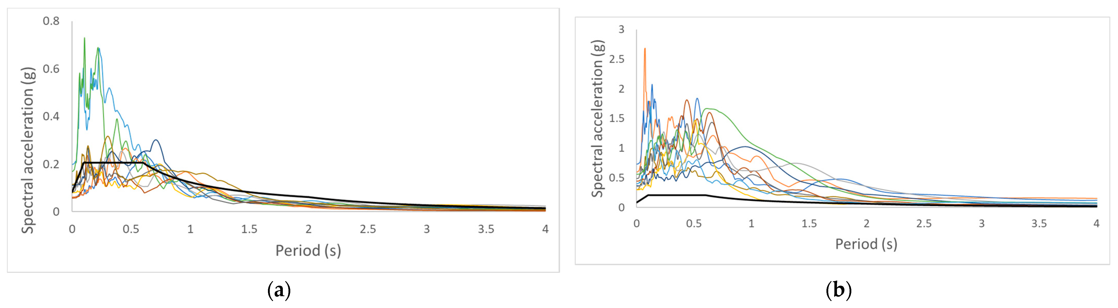
3.2.2. Nonlinear Dynamic Analysis

In addition to the variability associated with the record-to-record properties, the consideration of the dynamic analysis intends to evaluate the eventual importance of higher modes and, more importantly, the effects of cyclic degradation on the cladding panels. The dispersion in the structural response resulting from the specific properties associated with each accelerogram implies the need to consider several registers in order to obtain a wide and reliable set of results [31]. For this purpose, 2 groups of 10 accelerograms were selected. The records used in this study were selected from nearly 3500 records (including two horizontal and a vertical component) from a database of ground motions recorded in the Mediterranean region. The selection and scaling follow generically the strategy presented in [32], i.e., selecting the accelerograms whose geometric mean spectra of the two horizontal directions better approach the code spectral acceleration for the average of the fundamental periods along the two directions. Following this procedure, 10 ground motions were selected whose arithmetic mean along the period interval of 0.5 and 2 times the buildings’ average period of vibration.
Two groups of five records were considered in the present study. The first group of records was selected based on the seismic intensity characteristics of the place where the building is located, and whose response spectrum is presented in Figure 8a. To assess the behavior of the panels’ influence for higher levels of seismic action, a group of records was also selected considering the spectral accelerations five times higher than those considered in the first group (Figure 8b), representative of the seismic hazard expected in the southern region of Portugal. In order to optimize the time consumption of the analyses, every record was trimmed based on the 5% maximum peak ground acceleration following the work by Bommer et al. [33].
In order to account for the energy dissipation other than the hysteretic one, tangent stiffness proportional damping was considered, for a mean period of 0.7 s and a damping ratio of 1%. Considering the number of records, analyzed along the two main directions, with and without cladding panels, and with roof diaphragm (in the models with panels only), a total of 60 dynamic analyses were carried out.

4. Parametric Study

This section presents the results of the different analyses carried out aiming to assess the seismic performance of the cladding panels, as well as its impact in the overall performance of the building. For this purpose, different configurations of the building were considered, namely, varying the presence of the cladding panels and the in-plane stiffness of the roof. The different cases were analysed through modal analysis, as well as nonlinear static and dynamic analyses.

4.1. Modal Analysis

As expected, the presence of claddings panels increases the horizontal stiffness of the building leading to an increase in the frequency of vibrations. Yet, as shown in Table 1, this effect is more pronounced when the consideration of the panels in the facades is combined with a rigid diaphragm at the roof level (RD hereinafter), particularly along the Y direction where a large number of panels are aligned in their in-plane direction.

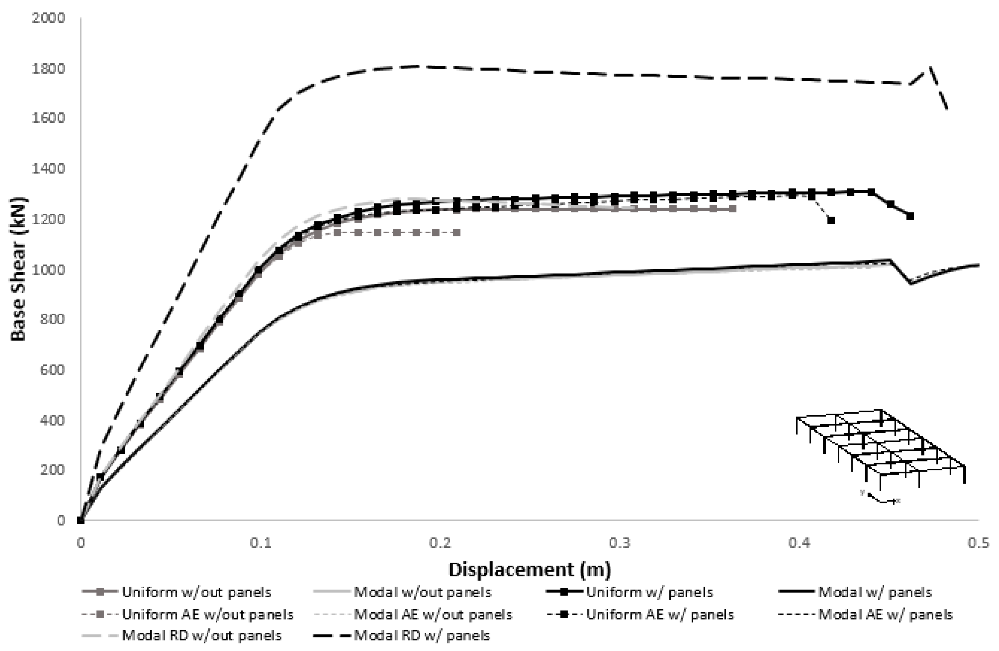
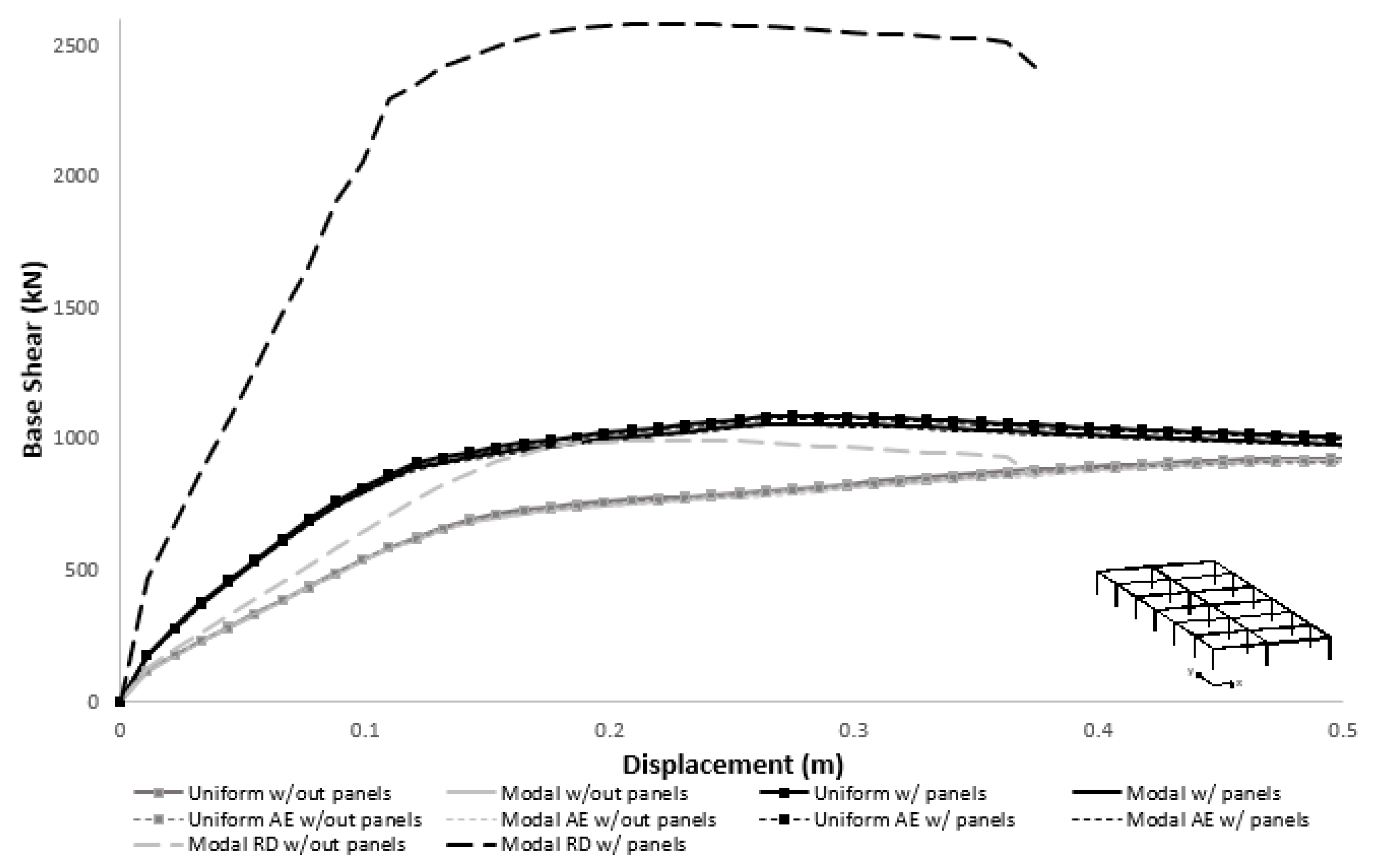
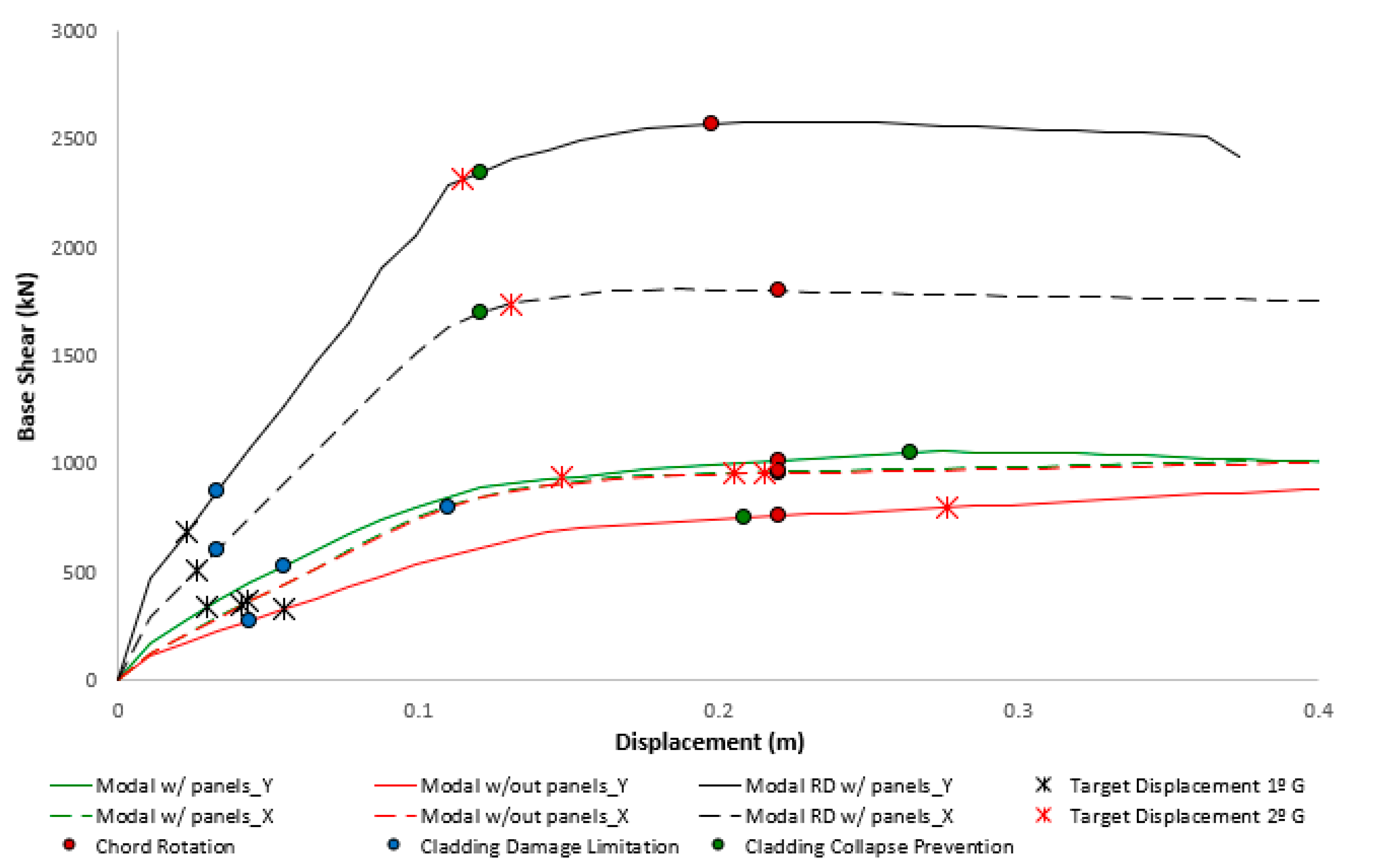
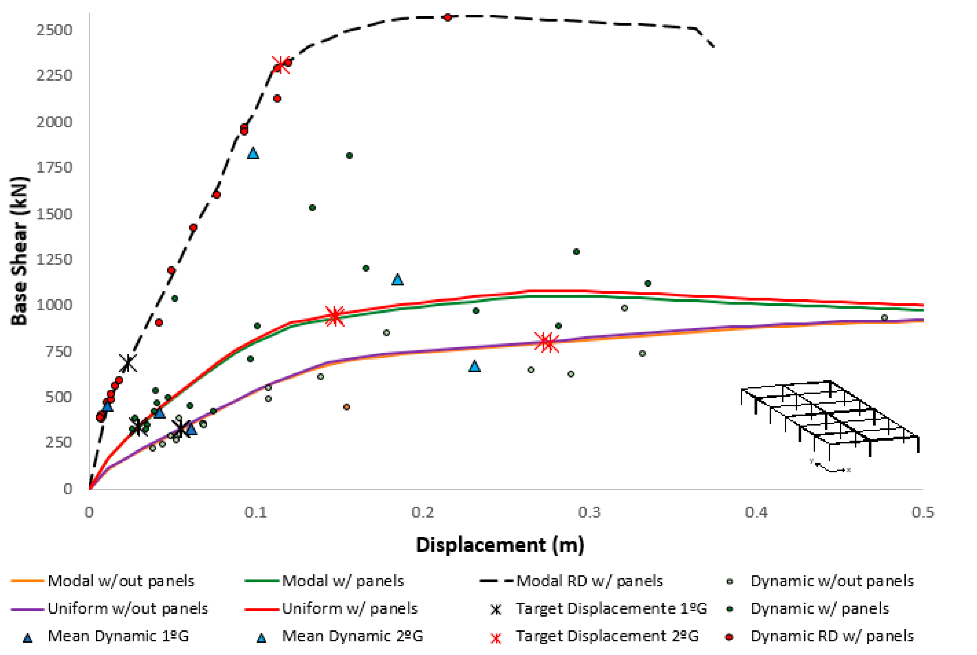
4.2. Nonlinear Static Analysis

Following the recommendations of Eurocode 8–Part 3 [29], two different load distributions were applied in the pushover analysis—a uniform one and a distribution proportional to the fundamental mode of vibration (designated as modal hereinafter). For both cases, an accidental eccentricity (AE) corresponding to a shift of the buildings mass in 5% of the building’s length was also considered, as prescribed by the same code. The capacity curves obtained for the two main directions, with and without panels (with and without panels) are presented in Figure 9 and Figure 10.
Regarding the influence of the cladding panels on the models without a rigid diaphragm, the results obtained in the pushover analyses revealed a distinct behavior along the two main directions. In the X direction it was apparent that the presence of the cladding panels had a minor contribution to the horizontal strength and stiffness, given that the panels were considered only in the extreme facades. In this case, the lateral deformation of the building was mainly concentrated in the middle frames. However, in the presence of a very large in-plane stiffness of the roof it was possible to mobilize the panels, as observed in the pushover analysis with the consideration of a rigid diaphragm. On the other hand, given that in the orthogonal direction only one out of the three frames do not include panels, the horizontal strength and stiffness increased significantly, even in the absence of a rigid diaphragm. It is therefore clear that the consideration of the infill panels is more relevant when the roof features a significant in-plane stiffness or if the building features relatively compact dimensions at least along one direction. The presence of a rigid diaphragm without panels has an insignificant effect on the global behavior.
In terms of lateral load distributions, for the analysis along the X direction, the uniform distribution (proportional to the buildings mass) differed significantly from the modal one, highlighting the natural tendency for a larger deformability in the frames near the middle of the building. Finally, regardless of the direction under analysis, the consideration of an accidental eccentricity resulted in minor differences in the behavior of the building.
When looking at the building’s performance for the seismic hazard level expected at its location, it was observed that the building’s main structure presents an adequate level of safety, given that no shear failures are expected and the lateral deformation for which the ¾ ultimate chord rotation (reference value for significant damage limit states) is first reached, occurs for a top displacement of approximately 0.2 m, much higher than the target displacement of approximately 0.05 m. The results were obtained assuming a limit knowledge level for which the material properties are divided by a confidence factor of 1.35. As illustrated in Figure 11, these conclusions are valid for different load distributions and in-plane roof stiffness. Nevertheless, when looking to the building’s performance for the seismic hazard level closer to the highest level expected in Portugal (approximately five times higher), these conclusions are not valid for the analysis without considering the cladding panels. Yet, the same conclusions cannot be drawn regarding the performance of the cladding panels. Based on the limit state thresholds proposed by Cornali et al. [34], namely 1 cm and 4 cm of relative deformation between panel connections, for damage limitation and collapse prevention, it was observed that some damage is expected in the pushover analysis with a modal distribution when the cladding panels are not included in the model. This observation highlights the importance to include the cladding panels in the models to attain a more reliable seismic assessment. For the second group of earthquakes, it was observed that some damage is expected in all analyses.

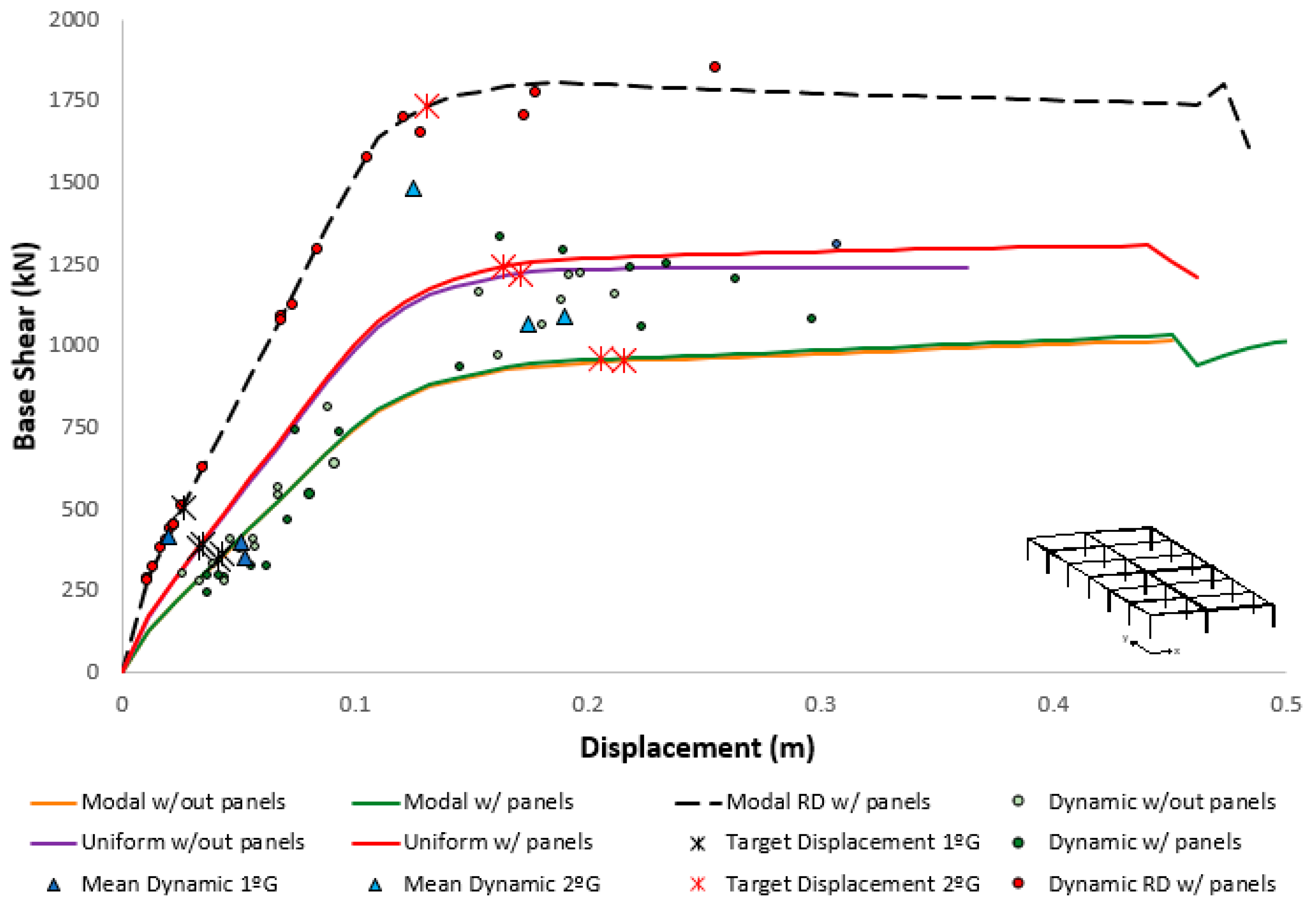
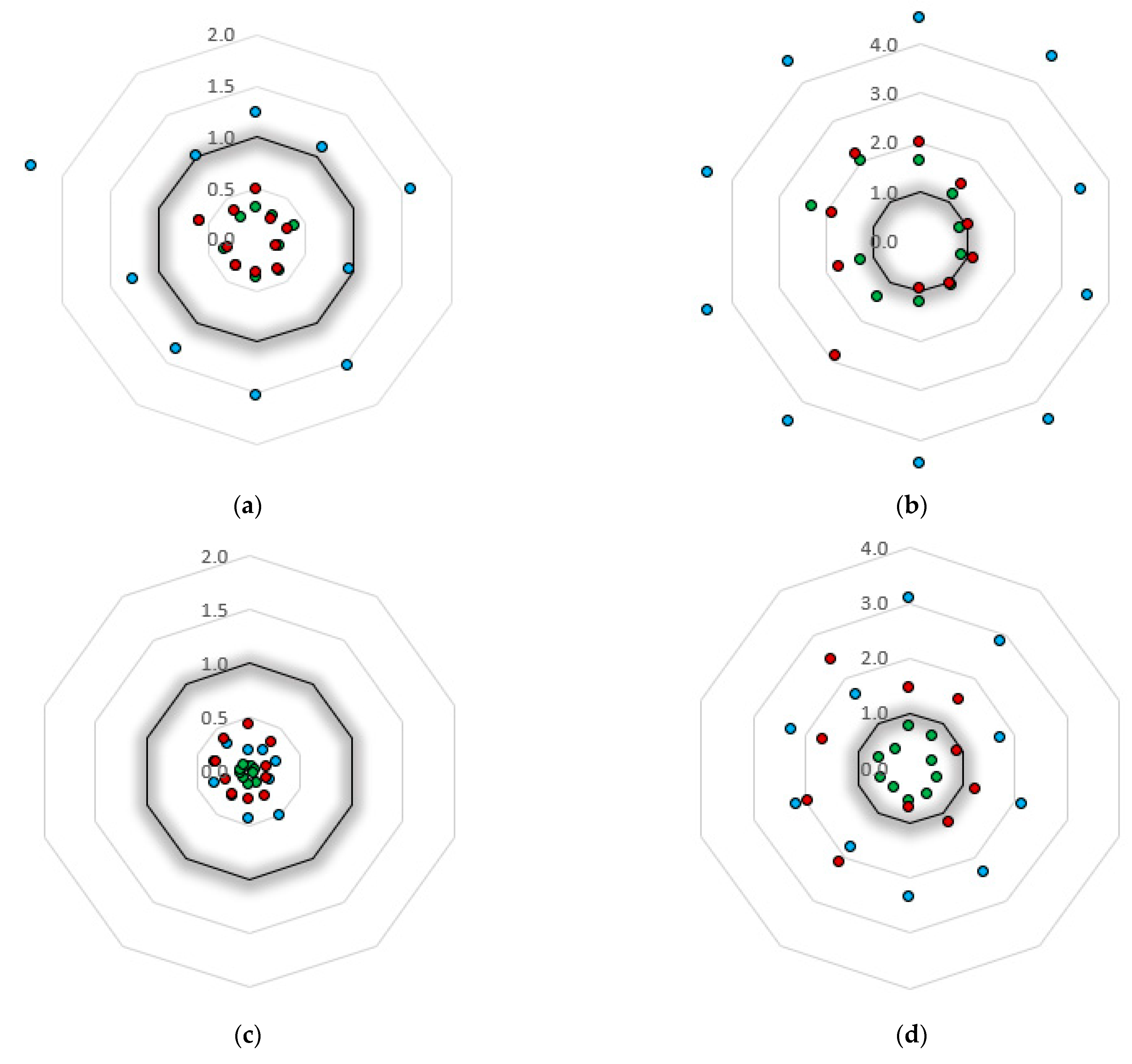
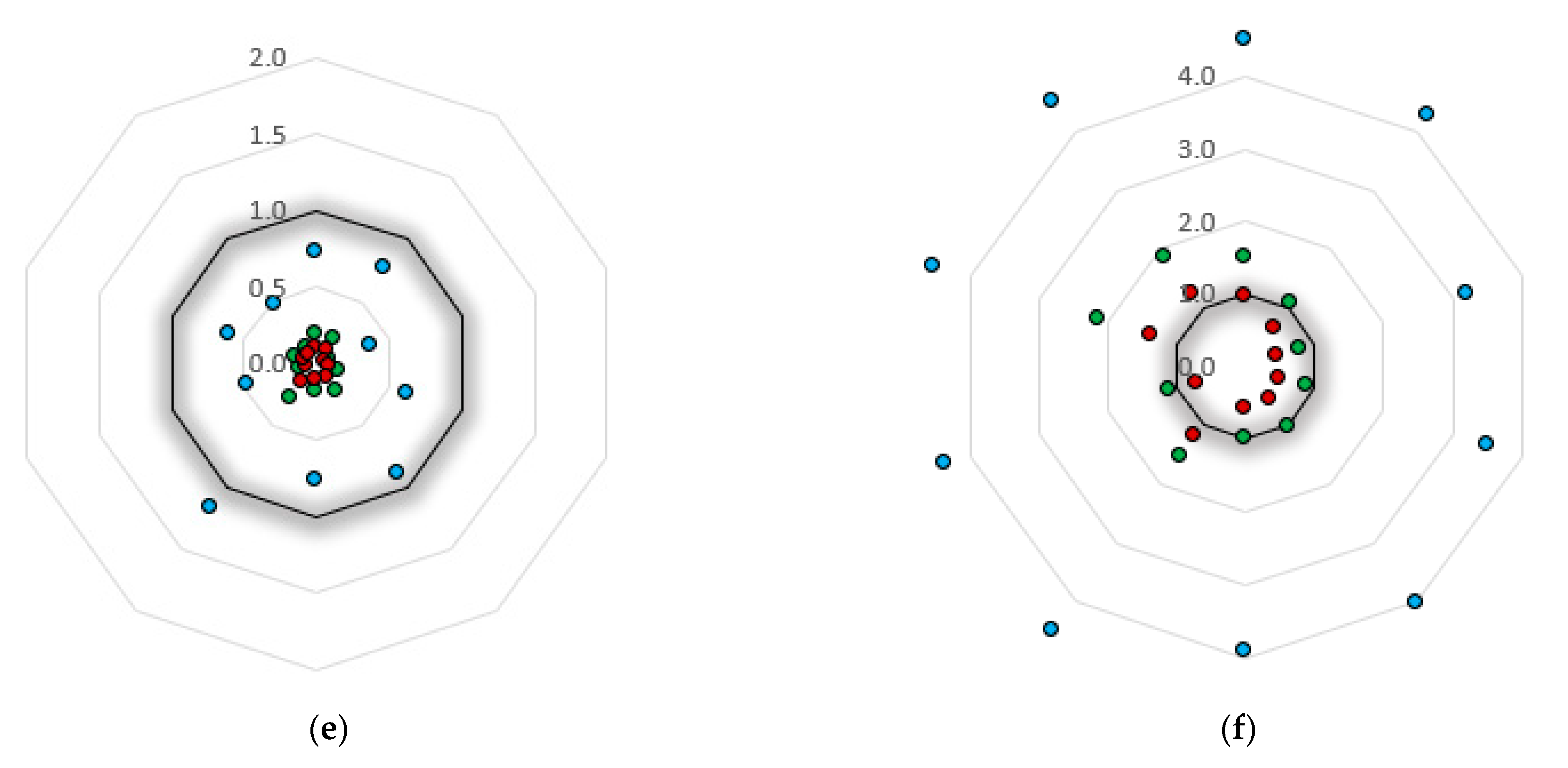
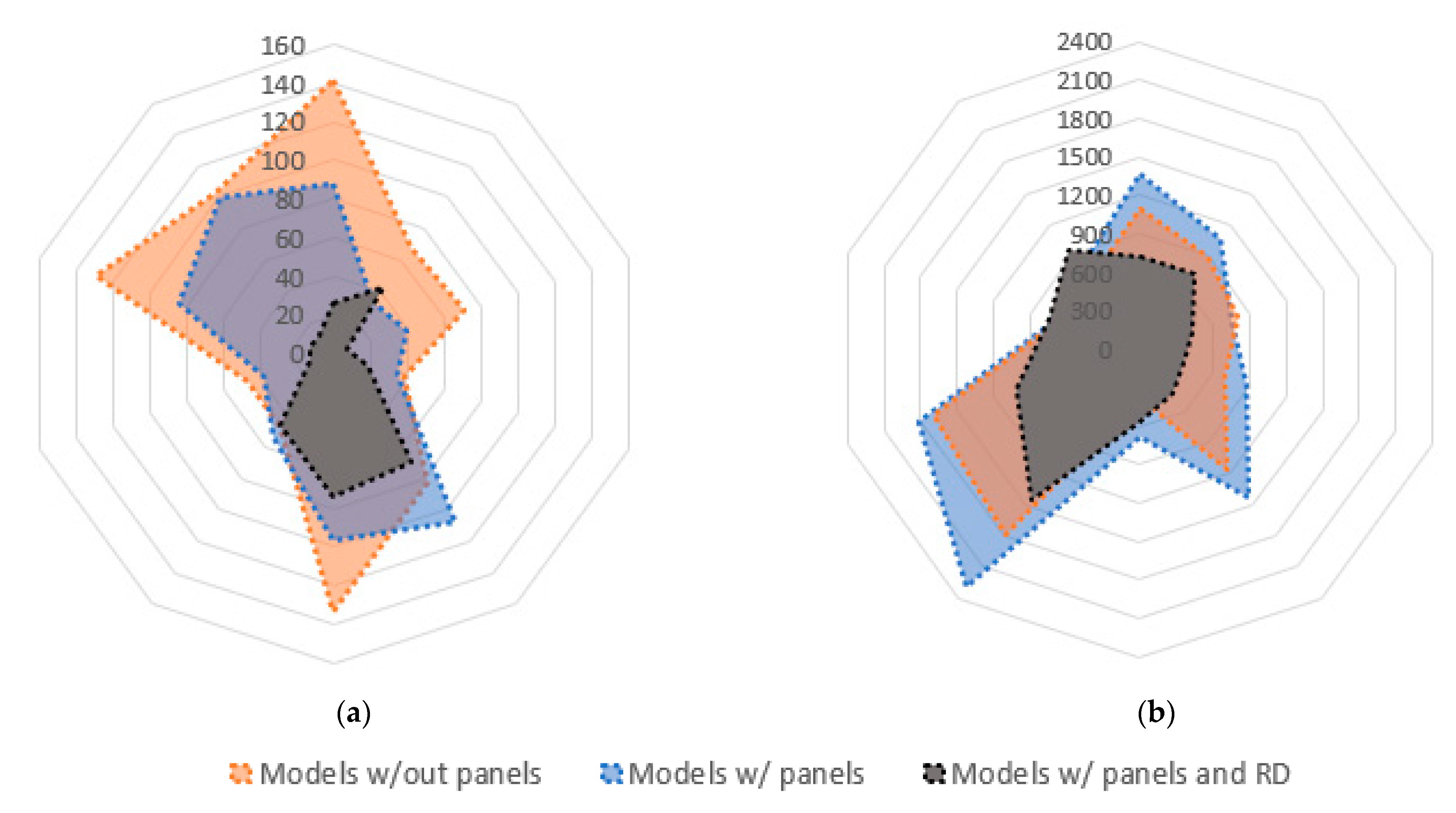
4.3. Nonlinear Dynamic Analysis

As previously described, two groups of records were considered, the first aiming to simulate the seismic performance for the expected seismic hazard at the building location, and the second, with an intensity approximately five times higher, to evaluate the performance under more severe seismic actions such as the ones expected in the regions of higher seismicity in Portugal. The results of the nonlinear dynamic analyses presented in the following figures represent the combination of the maximum top displacement with the maximum base shear experienced during each record. It is important to perceive that some of these points might be fictitious, as they do not necessarily occur at the same instant. Figure 12 and Figure 13 shows the results of both dynamic and pushover analysis along the X and Y directions, respectively.
In general, the pushover curves obtained for each direction were in good agreement with the set of records used to perform the dynamic analysis, particularly in the linear range. Yet, some dynamic analyses diverged significantly in terms of maximum base shear as the structure enters the inelastic regime, associated with the (more) unpredictable behavior in this regime, especially when considering the seismic loads along the two directions simultaneously.
For this reason, much lower differences were observed in the models featuring cladding panels and rigid diaphragm due to the fact that not only the building response remained essentially in the elastic range, but also because these constraints reduced the complexity of the dynamic behavior with the prevalence of the fundamental modes of vibration and the reduction of the modal mass associated with the higher modes.
Regarding the consideration of the panels, along the Y direction, the results of the nonlinear dynamic analyses were similar to the pushover ones, mainly in the first group of earthquakes that was located more in the elastic part. On the other hand, in the X direction it is possible to observe that the results of maximum displacements and forces of the nonlinear dynamic analyses were closer to the elastic region of the modal capacity curve and approached the uniform one for increasing seismic actions.
In this regard, it is important to note that the uniform distribution is particularly relevant and recommended for multistorey buildings with a nearly uniform distribution of mass along the height, such as the masonry ones, and for buildings prone to develop a soft-storey mechanism at the ground level. The present case study does not satisfy any of these conditions and, therefore, the uniform distribution is taken as less representative than the modal one.
Regarding the seismic safety of the building, the values obtained with the dynamic analyses corroborated the outcome of the static ones, with the average of the maximum base shear and top displacement similar to the target point determined in the static procedure. It is recalled that the consideration of the averaged response is accepted by Eurocode 8–Part 1 [25] whenever the dynamic response is obtained with at least seven nonlinear analyses, as is the present case.
In terms of the column’s performance, no damage is expected for the analysis of the first group of records. For the second group of records, that assess the performance for higher intensities, several columns in several analyses overcome the accepted chord rotation, similarly to what was observed for the static analyses. This observation is more evident in Figure 14, which presents the damage ratios, taken as the maximum element seismic demand over the element’s capacity, for the columns chord rotation, cladding panel damage limitation and collapse prevention limit states, found in the different dynamic analyses carried out. Nonetheless, it is important to highlight the reduction in the column damage indicator when the building features infill panels with a rigid diaphragm. In these cases, a relevant fraction of the seismic loads is supported by the cladding panels, reducing, in this way, the overall horizontal displacement demand on the buildings.
Concerning the performance of the cladding panels, for the first group of records, the panels suffered negligible damage, while for the second group, the damage was more significant, exceeding the limit states in most of the cases. Yet, the consideration of the panels in the model without a rigid diaphragm reduced the deformation demand in those frames, decreasing the damage expected at the panel’s connections. In the presence of a rigid diaphragm, on the other hand, the cladding panels attracted an important fraction of the seismic loads resulting in an increase of the level of damage expected in these elements. It should be noted that, in several cases, the cladding damage limitation points represented with a 4.5 scale in Figure 14, corresponded to larger values, that were bracketed to this limit to ensure an adequate representation of the other limit states.
A final comment to the energy dissipation, which is a fundamental property in RC elements subjected to seismic demands [35], enabling damage to be accommodated without significant loss of strength [36]. The results of the total cumulative dissipated energy (KJ) shown in Figure 15 shows that, for the case study under analysis, the panels have a small contribution to the total energy dissipation of the system. This is particularly notable in the models featuring cladding panels and a rigid diaphragm, representing the cases in which the panels are subjected to higher demand, in which the hysteretic energy dissipation is significantly lower than in the other cases. As depicted in Figure 16, representing a panel hysteretic curve from the 2° group of records, the panels can sustain an important fraction of the horizontal forces but only during its first cycle along a given direction. Once a given panel connection deformation is reached, the following cycles within this relative maximum occur with a residual horizontal force and, therefore, with a marginal energy dissipation. Although in a less pronounced manner, this effect is also visible in the models without a rigid diaphragm (with and without panels). In this case, however, for the first group, the presence of panels contributes to further reducing the element demands that are essentially in the elastic regime, whilst in the second group, a larger deformation demand is observed in the bare frames that leads to a larger demand and energy dissipation in the columns, as previously observed.

5. Conclusions

In this study, the seismic analysis of a PRC building representative of the Portuguese industrial park was carried out, considering numerical analyses with and without the influence of the cladding panels. The numerical models, considering the presence of cladding panels, make use of a simplified macroelement that simulates the influence of the panels on the main structure. The model was calibrated based on experimental tests to simulate the capacity of commonly employed cladding connections, as well as the interaction of cladding panels with PRC industrial buildings.
The seismic behavior of the structure was assessed considering both nonlinear static and dynamic procedures. According to the results obtained through these analyses, it was concluded that the influence of the panels might be important, especially in relatively compact buildings or in the presence of rigid diaphragms, expressing an overall increase in strength and stiffness. However, if the building is significantly elongated and does not have a rigid diaphragm, the contribution of the panels might be negligible. It should be highlighted that in conventional buildings the actual in-plan stiffness of the roof should lie somewhere between the two extreme conditions considered. In addition to the variations in the overall building’s responses, it was observed that the nonconsideration of cladding panels in the numerical model might result in a conservative assessment of the nonstructural components (including the panels itself), which are indirectly evaluated through the frame deformations. This observation confirms the importance of considering representative numerical models and including the cladding panels, if present, to attain a more reliable seismic assessment.
Regarding the type of the analysis employed in the seismic assessment, in general, the results obtained with nonlinear static analyses are in good agreement with the nonlinear dynamic ones, indicating that these appear to be a reliable option, especially considering the relative simplicity of static analysis in comparison with the dynamic counterpart. Nonetheless, despite the large dispersion observed in the dynamic analysis for high intensity levels, the seismic demand obtained tended to be higher than that obtained with the static ones, showing that the latter might lead to a nonconservative seismic assessment.
In summary, the results obtained indicate that the use of static procedures represents a reliable analysis procedure, in line with those obtained with the dynamic counterpart, especially in the (essentially) elastic regime. The results also demonstrate that the analysis carried out without cladding panels tended to produce a conservative seismic assessment and, therefore, the inclusion of these nonstructural elements in the numerical models is advised. Regarding the expected seismic performance of the existing cladding panels, the results indicate that damage is expected to occur in these elements under low seismic actions. This information brings attention for the need to update the current practice with more efficient connections and put in practice measures to limit the damage in existing structures. Despite the effort made to select a building representative of the existing building stock in the Mediterranean region, the conclusions drawn in this paper are naturally limited to the building and limited records considered in the study presented.

Author Contributions

Conceptualization, R.S. and H.R.; methodology, R.S. and H.R.; formal analysis, L.O.; investigation, L.O.; writing—original draft preparation, L.O. and R.S.; writing—review and editing, H.R. and P.F.; supervision, H.R. and P.F.; project administration, H.R. All authors have read and agreed to the published version of the manuscript.

Funding

This work was financially supported by Project POCI-01-0145-FEDER-028439-“SeismisPRECAST Seismic performance ASSessment of existing Precast Industrial buildings and development of Innovative Retrofitting sustainable solutions,” funded by FEDER funds through COMPETE2020—Programa Operacional Competitividade e Internacionalização (POCI) and by national funds (PIDDAC) through FCT/MCTES. The first author acknowledged FCT—Fundação para a Ciência e a Tecnologia—namely through the PhD grant of the first author with reference 2020.08152.BD.

Data Availability Statement

Not applicable.

Conflicts of Interest

The authors declare no conflict of interest.

References

  1. Batalha, N.; Rodrigues, H.; Varum, H. Seismic performance of RC precast industrial buildings—Learning with the past earthquakes. Innov. Infrastruct. Solut. 2018, 4, 4. [Google Scholar] [CrossRef]
  2. Fischinger, M.; Zoubek, B.; Kramar, M.; Isaković, T. Cyclic response of dowel connections in precast structures. In Proceedings of the 15th World Conference on Earthquake Engineering, Lisbon, Portugal, 24–28 September 2012. [Google Scholar]
  3. Belleri, A.; Torquati, M.; Marini, A.; Riva, P. Horizontal cladding panels: In-plane seismic performance in precast concrete buildings. Bull. Earthq. Eng. 2016, 14, 1103–1129. [Google Scholar] [CrossRef]
  4. Dal Lago, B.; Bianchi, S.; Biondini, F.; Toniolo, G. Dissipative diaphragm connections for precast structures with cladding panels under seismic action. In Proceedings of the 16th European Conference on Earthquake Engineering, Thessaloniki, Greek, 18–21 June 2018; pp. 1–12. [Google Scholar]
  5. Del Monte, E.; Falsini, C.; Boschi, S.; Menichini, G.; Orlando, M. An innovative cladding panel connection for RC precast buildings. Bull. Earthq. Eng. 2018, 17, 845–865. [Google Scholar] [CrossRef]
  6. Liberatore, L.; Sorrentino, L.; Liberatore, D.; Decanini, L.D. Failure of industrial structures induced by the Emilia (Italy) 2012 earthquakes. Eng. Fail. Anal. 2013, 34, 629–647. [Google Scholar] [CrossRef]
  7. Magliulo, G.; Ercolino, M.; Petrone, C.; Coppola, O.; Manfredi, G. The Emilia earthquake: Seismic performance of precast reinforced concrete buildings. Earthq. Spectra 2014, 30, 891–912. [Google Scholar] [CrossRef]
  8. Savoia, M.; Buratti, N.; Vincenzi, L. Damage and collapses in industrial precast buildings after the 2012 Emilia earthquake. Eng. Struct. 2017, 137, 162–180. [Google Scholar] [CrossRef]
  9. Bournas, D.A.; Negro, P.; Taucer, F.F. Performance of industrial buildings during the Emilia earthquakes in Northern Italy and recommendations for their strengthening. Bull. Earthq. Eng. 2013, 12, 2383–2404. [Google Scholar] [CrossRef]
  10. Belleri, A.; Brunesi, E.; Nascimbene, R.; Pagani, M.; Riva, P. Seismic performance of precast industrial facilities following major earthquakes in the Italian territory. J. Perform. Constr. Facil. 2015, 29, 1–10. [Google Scholar] [CrossRef] [Green Version]
  11. Rodrigues, H.; Sousa, R.; Vitorino, H.; Batalha, N.; Varum, H.; Fernandes, P. Characterisation of Portuguese RC precast industrial building stock. Adv. Civ. Eng. 2020, 2020, 1–19. [Google Scholar] [CrossRef]
  12. Arnold, C. Cladding design: Architectural Trends and Their Influence on Seismic Design. In Architectural Precast Concrete Cladding-It’s Contribution to Lateral Resistance of Buildings; PCI: Chicago, IL, USA, 1989. [Google Scholar]
  13. Colombo, A.; Negro, P.; Toniolo, G. The influence of claddings on the seismic response of precast structures: The safecladding project. In Proceedings of the 2nd ECEES, Istanbul, Turkey, 25–29 August 2014; pp. 1–12. [Google Scholar]
  14. Magliulo, G.; Ercolino, M.; Manfredi, G. Influence of cladding panels on the first period of one-story precast buildings. Bull. Earthq. Eng. 2014, 13, 1531–1555. [Google Scholar] [CrossRef]
  15. Scalbi, A.; Tornaghi, M.L.; Negro, P. Safecladding Project: Pseudodynamic Testing on Precast Structures with Horizontal Cladding Panels. In Proceedings of the 16th European Conference on Earthquake Engineering, Thessaloniki, Greece, 18–21 June 2018; pp. 1–12. [Google Scholar]
  16. Toniolo, G.; Colombo, A. Precast concrete structures: The lessons learned from the L’Aquila earthquake. Struct. Concr. 2012, 13, 73–83. [Google Scholar] [CrossRef]
  17. Ercolino, M.; Magliulo, G.; Coppola, O.; Manfredi, G. Code formula for the fundamental period of RC precast buildings. In Proceedings of the Second European Conference on Earthquake Engineering and Seismology, Istanbul, Turkey, 25–29 August 2014; pp. 1–10. [Google Scholar]
  18. Zoubek, B.; Fischinger, M.; Isaković, T. Cyclic response of hammer-head strap cladding-to-structure connections used in RC precast building. Eng. Struct. 2016, 119, 135–148. [Google Scholar] [CrossRef]
  19. Sousa, R.; Batalha, N.; Silva, V.; Rodrigues, H. Seismic fragility functions for Portuguese RC precast buildings. Bull. Earthq. Eng. 2020, 1–18. [Google Scholar] [CrossRef]
  20. Bressanelli, M.E.; Bellotti, D.; Belleri, A.; Cavalieri, F.; Riva, P.; Nascimbene, R. Influence of modelling assumptions on the seismic risk of industrial precast concrete structures. Front. Built Environ. 2021, 7. [Google Scholar] [CrossRef]
  21. Babič, A.; Dolšek, M. Seismic fragility functions of industrial precast building classes. Eng. Struct. 2016, 118, 357–370. [Google Scholar] [CrossRef]
  22. Starešinič, G.; Zoubek, B.; Gams, M.; Isaković, T.; Fischinger, M. Modelling in-plane dynamic response of a fastening system for horizontal concrete facade panels in RC precast buildings. Eng. Struct. 2020, 224, 111210. [Google Scholar] [CrossRef]
  23. Rodrigues, H.; Varum, H.; Costa, A. Simplified macro-model for infill masonry panels. J. Earthq. Eng. 2010, 14, 390–416. [Google Scholar] [CrossRef]
  24. Seismosoft. SeismoStruct—A Computer Program for Static and Dynamic Nonlinear Analysis of Framed Structures. 2020. Available online: www.seismosoft.com (accessed on 1 September 2021).
  25. Eurocódigo 8-Projecto de Estruturas para resistência aos sismos. In Parte 1: Regras Gerais, Acções Sísmicas e Regras Para Edifícios; Instituto Português da Qualidade: Caparica, Portugal, 2010.
  26. Sousa, R.; Almeida, J.P.; Correia, A.A.; Pinho, R. Shake table blind prediction tests: Contributions for improved fiber-based frame modelling. J. Earthq. Eng. 2018, 24, 1435–1476. [Google Scholar] [CrossRef]
  27. Mander, J.B.; Priestley, M.J.N.; Park, R. Theoretical StressStrain Model for Confined Concrete. J. Struct. Eng. 1988, 114, 1804–1826. [Google Scholar] [CrossRef] [Green Version]
  28. Menegotto, M.; Pinto, P. Method of Analysis for Cyclically Loaded R.C. Plane Frames Including Changes in Geometry and Non-Elastic Behavior of Elements under Combined Normal Force and Bending. In Symposium Resistance and Ultimate Deformability of Structures Acted on by Well-Defined Repeated Loads; International Association for Bridge and Structural Engineering: Zurich, Switzerland, 1973. [Google Scholar]
  29. Eurocódigo 8-Projecto de estruturas para resistência aos sismos. In Parte 3: Avaliação e Reabilitação de Edifícios; Instituto Português da Qualidade: Caparica, Portugal, 2017.
  30. Fajfar, P. Capacity spectrum method based on inelastic demansd spectra. Earthq. Enging. Struct. Dyn. 1999, 28, 979–993. [Google Scholar] [CrossRef]
  31. Sousa, R.; Bianchi, F.; Pinho, R.; Nascimbene, R.; Kazantzidou, D. Modelling issues on Seismic Assessment of Irregular RC Structures. In Proceedings of the III ECCOMAS Thematic Conference on Computational Methods in Structural Dynamics and Earthquake Engineering (COMPDYN), Island of Corfu, Greece, 26–28 May 2011. [Google Scholar]
  32. FEMA P-58-1. Seismic Performance Assessment of Buildings; Volume 1, Issue December 2018, 2018. Available online: https://femap58.atcouncil.org/%0Ahttps://www.fema.gov/media-library/assets/documents/90380 (accessed on 1 September 2021).
  33. Bommer, J.; Martínez-Pereira, A. The effective duration of earthquake strong motion. J. Earthq. Eng. 1999, 3, 127–172. [Google Scholar] [CrossRef]
  34. Cornali, F.; Belleri, A.; Marini, A.; Riva, P. Influence of modelling assumptions in the expected loss evaluation of a precast industrial building. Procedia Eng. 2017, 199, 3510–3515. [Google Scholar] [CrossRef]
  35. Rodrigues, H.; Varum, H.; Arede, A.; Costa, A. A comparative analysis of energy dissipation and equivalent viscous damping of RC columns subjected to uniaxial and biaxial loading. Eng. Struct. 2012, 35, 149–164. [Google Scholar] [CrossRef] [Green Version]
  36. Elmenshawi, A.; Brown, T. Hysteretic energy and damping capacity of flexural elements constructed with different concrete strengths. Eng. Struct. 2009, 32, 297–305. [Google Scholar] [CrossRef]
Figure 1. Cladding panels failure [1]. (a) Horizontal cladding panel failure and (b) connection failure on cladding panels (top view).
Buildings 11 00400 g001
Figure 2. Typical Portuguese industrial building. (a) Typical arrangement with horizontal cladding panels and (b) connection between the column and cladding panel.
Buildings 11 00400 g002
Figure 3. Example of the application of the simplified macroelement for the simulation of cladding panels.
Buildings 11 00400 g003
Figure 4. Calibration of the hysteretic response based on the “Standard” connection tested by Del Monte et al. [5].
Buildings 11 00400 g004
Figure 5. Definition of the parameters adopted in the macroelement in. (a) Pinched asymmetric curve model [24] and (b) parameters adopted.
Buildings 11 00400 g005
Figure 6. Building under study. (a) Three-dimensional overview of the building under study with panels and with a rigid diaphragm at the roof level and (b) layout of cladding panels with associated connections along the Y direction.
Buildings 11 00400 g006
Figure 7. Transversal sections of the elements considered in the numerical model. (a) Central columns, (b) façade columns, (c) longitudinal beams and (d) transversal beams.
Buildings 11 00400 g007
Figure 8. Response spectra of the two groups of earthquakes in relation to the building under study. (a) 1° group and (b) 2° group.
Buildings 11 00400 g008
Figure 9. Capacity curves for the models with and without cladding panels in the X direction.
Buildings 11 00400 g009
Figure 10. Capacity curves for the models with and without cladding panels in the Y direction.
Buildings 11 00400 g010
Figure 11. Evaluation of structural and nonstructural performance for different modelling options.
Buildings 11 00400 g011
Figure 12. Comparison of the results of the different analyses for the models with and without cladding panels in the X direction.
Buildings 11 00400 g012
Figure 13. Comparison of the results from different analyses for the models with and without cladding panels in the Y direction.
Buildings 11 00400 g013
Figure 14. Damage ratios at the columns and cladding panels for the dynamic analysis: (a) 1° group w/out panels, (b) 2° group w/out panels, (c) 1° group w/panels, (d) 2° group w/panels, (e) 1° group w/panels and RD and (f) 2° group w/panels and RD.
Buildings 11 00400 g014aBuildings 11 00400 g014b
Figure 15. Total cumulative dissipated energy: (a) 1° group and (b) 2° group.
Buildings 11 00400 g015
Figure 16. Cladding panel hysteretic behavior from the 2° group of records and associated limit states.
Buildings 11 00400 g016
Table 1. Frequency and vibration modes of the different building configurations.
Frequency with PanelsFrequency without Panels
DirectionW/diaphragm
(Hz)
W/out diaphragm
(Hz)
W/rigid diaphragm
(Hz)
W/out diaphragm
(Hz)
Y2.4771.4851.4281.339
X2.0831.6921.7241.686
Torsion3.0181.7591.9061.816
Publisher’s Note: MDPI stays neutral with regard to jurisdictional claims in published maps and institutional affiliations.

