Article

Experimental Study on the Behavior of Steel–Concrete Composite Decks with Different Shear Span-to-Depth Ratios

by
Sayan Sirimontree
1,
Chanachai Thongchom
1,*,
Suraparb Keawsawasvong
1,
Peem Nuaklong
1,
Pitcha Jongvivatsakul
2,
Warayut Dokduea
1,
Linh Van Hong Bui
3 and
Ehsan Noroozinejad Farsangi
4
1
Department of Civil Engineering, Thammasat School of Engineering, Faculty of Engineering, Thammasat University, Pathum Thani 12121, Thailand
2
Innovative Construction Materials Research Unit, Department of Civil Engineering, Chulalongkorn University, Bangkok 10330, Thailand
3
Faculty of Civil Engineering, Ho Chi Minh City Open University, Ho Chi Minh City 700000, Vietnam
4
Faculty of Civil and Surveying Engineering, Graduate University of Advanced Technology, Kerman 7631818356, Iran
*
Author to whom correspondence should be addressed.
Buildings 2021, 11(12), 624; https://doi.org/10.3390/buildings11120624
Submission received: 6 November 2021 / Revised: 4 December 2021 / Accepted: 6 December 2021 / Published: 8 December 2021
(This article belongs to the Special Issue Sustainable Building Infrastructure and Resilience)

Abstract

:
This paper presents the results of an experimental study on the mechanical behaviors of steel‒concrete composite decks with different shear span-to-depth ratios. Herein, four composite decks categorized into two types with shear span-to-depth ratios of 2.5 and 4.6 are designed for an experimental program. The decks then undergo the four-point bending tests until failure to investigate the structural responses, such as the load, displacement, crack mechanism, and failure mode. Conventional section analysis is used to derive the flexural strength of composite decks in comparison with the test results. Additionally, the ductility of the composite decks is assessed based on the displacement indices. The analysis results demonstrate that the stiffness and capacity of the composite deck increase with the decrease in the shear span length. However, the ductility of the composite slabs increases with the shear span length. The flexural strengths predicted by section analysis overestimate the actual test results. The shear span-to-depth ratio affects the crack mechanism of the composite decks.

1. Introduction

Besides conventional steel-reinforced concrete (RC) structures, structures made by steel‒concrete composite systems have been gained the attention of researchers and engineers. A novel composite metal decking system with innovative technology is made from cold-formed steel [1]. This composite deck utilizes cold-formed profiled sheets identical to those used as roofing products [2], which are poured over the profiled sheets. Nowadays, this construction method has become more favorable for clients to use in their construction projects since it is faster and safer than the conventional RC slab. There are two key reasons for the use of the cold-formed profiled sheet for producing composite slab systems. First, the cold-formed profiled sheet can be used as formwork during the casting of concrete [3]. Second, at the working stage, the profiled sheet acts as the main steel tension reinforcement that can withstand high tensile forces [4].
However, an additional secondary reinforcement must be placed above the profiled steel sheet to reduce damage caused by the shrinkage and temperature. The interface between the steel sheet and concrete is basically subjected to longitudinal shear stress induced by the weight of concrete block above the sheet. This results in the development of the longitudinal shear stress accumulating as loading acting on the supports. Therefore, bolted shear connectors (e.g., stud bolt) must be implemented at the area around the supports in order to overcome the longitudinal shear stress occurring in this zone. Akhand et al. [5] carried out experiments to investigate the strength of re-entrant decking under combined flexure and web crippling by using cold-formed sheeting (Bondek-II sheeting) with a thickness of 1 mm. They found that this kind of decking had higher buckling sensitivity. Nonlinear finite element models were also proposed in their study to predict the moment–rotation characteristics of this decking by comparing it with the experimental data. The advanced design approach for the composite slab was presented by Crisinel and Marimon [6] and can be used to predict the moment–curvature relationship at the critical cross-section of a composite slab. Their design approach was verified by comparison with the results from the large-scale tests.
The behaviors of a steel-concrete composite deck with profiled sheeting and perfobond-rib shear connectors were examined by Kim and Jeong [7]. It was found that the composite deck slabs can carry more load, approximately two and a half times, compared to the conventional RC deck slabs. The utilization of waste materials such as palm oil clinker aggregates as a full replacement for normal aggregates of lightweight concrete was demonstrated by Mohammed et al. [8]. This lightweight concrete was then used to produce composite-slab specimens, which were tested to acquire the load versus strain of these composite slabs made from palm oil clinker aggregates. An investigation of the behavior of the composite deck slab made from trapezoidal profiled stainless steel decking sheets was carried out by Prajapati et al. [9]. In an experiment by Baskar and Jeyasehar [10], an interlocking system was implemented in the composite deck slab system to increase the frictional and mechanical interlocking at the interface between the steel sheet and concrete. This interlocking system can well resist the shear stress longitudinally transferred at the interface, which strengthens the interaction between the steel and the concrete. Hedaoo et al. [11] used trapezoidal profiled galvanized iron sheets as components of eighteen composite slab specimens to be tested under static and cyclic loading. The structural behavior as well as the loading capacity of these composite slab systems was presented in their work. They also found that the preliminary cycling loading can initially cause the failure of chemical bonds at the interface between concrete and steel.
Regarding the utilization of numerical techniques, Abdullah and Samuel [12] and Chen [13] provided results obtained from a bending test, which were then used to develop finite element models for estimating the horizontal shear bond in composite slabs. The modeling and analysis of the ultimate behavior of two-way composite slabs were presented by Eldib et al. [14], who adopted the finite element method with non-linear material properties. Note that two-way composite slabs mean that the slabs can carry the loads along with both directions. Composite slabs with a length ratio based on the longer edge to the shorter edge less than two can be considered two-way slabs. The interface contact model was activated in their simulation to increase the accuracy of finite element models. The shear bond mechanism of composite slabs was investigated by Chen and Shi [15], who conducted both full-size tests and finite element models of concrete slabs composited with cold-formed profiled steel decks.
The longitudinal shear stress owing to the heavy weight of the concrete block above the steel sheet is one of the fundamental problems in the construction and design of composite deck slabs. Marimuthu et al. [16] studied the behavior of composite deck slabs by utilizing embossed trapezoidal profiled sheets. By comparing their experimental results with European Standards [17] and British Standards [18], they concluded that the stud connector was an essential part to be implemented at the bonding zone between the concrete and profile steel sheet to enhance the capacity of bonding. Baskar [19] also confirmed that the use of stud shear connectors could enhance the ultimate strength and ductility of the composite deck system. Lakshmikandhan et al. [20] later investigated the effect of different shear transferring mechanisms. The indentation embossment and fastening studs were carried out in their work. They found that the strength, stiffness, flexural capacity, and load-carrying capacity of composite deck slabs increased when using the mechanical shear connectors. More details on the longitudinal shear behavior of composite deck slabs can be found elsewhere [21,22,23,24,25,26]. Recently, an experimental investigation on the connection behavior of composite decks by varying the types of cold-formed profiled sheets was carried out by Avudaiappan et al. [3].
One of the most important factors influencing the strengths of RC members is the shear span-to-depth ratio [27]. This factor plays a major role in determining the performance and failure behavior of slender RC beams used for tall building construction [28]. For example, the shear strength of the RC beams increased with decreasing shear span-to-depth ratio due to the mechanism, commonly refer to as the “strut and tie action” [29,30]. RC beams with a low shear span-to-depth ratio are prone to suffer shear-compression failure mode [31]. Despite extensive research on this subject, very few experimental studies on the influence of the shear span-to-depth ratio on behaviors of slender composite metal decks have been reported in the literature. Therefore, the understanding of the failure mechanism and bonding resistance in the composite metal decks under bending needs to be improved.
The aim of this research is to assess the flexural strength and behavior of one-way steel‒concrete composite decks, which have length ratios of the longer edge to the shorter edge greater than two. Four composite decks were fabricated and underwent four-point bending tests. The effects of the shear span-to-depth ratio on the structural responses of composite metal decks were investigated. Herein, the composite metal deck was made from cold-formed steel sheet. The load-displacement curves of tested specimens are presented. Histograms for cracking and the maximum moment of all composite metal decks were also assessed. The test results were compared with the flexural strength calculated by using the section analysis. The crack mechanism and failure mode of the test composite decks were examined. Further, the ductility of the composite decks under the effect of the shear span-to-depth ratio was evaluated.

2. Experimental Program
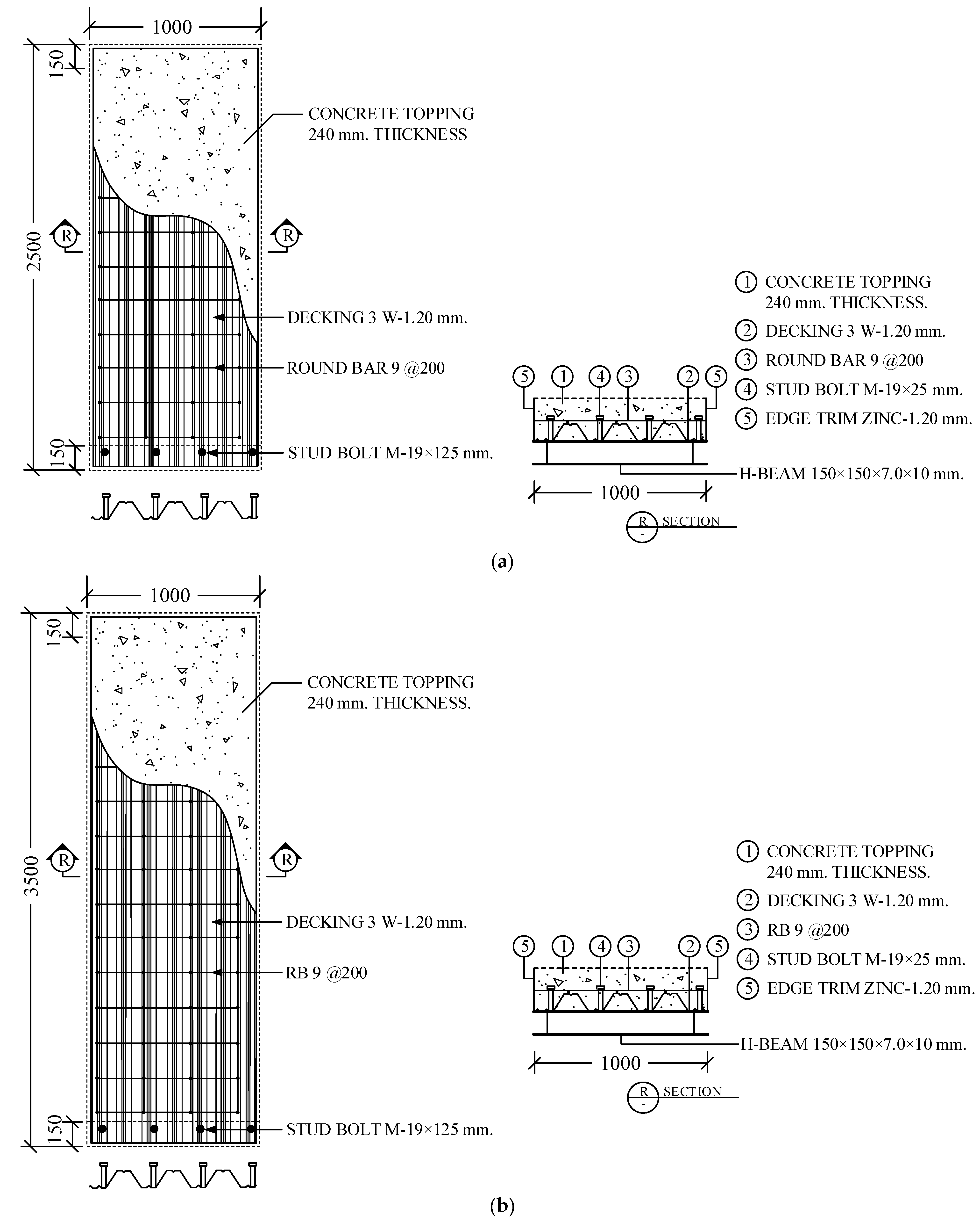
2.1. Test Specimens

Concrete specimens, including the composite deck and standard cylinders (150 mm × 300 mm), were cast at the same time. The concrete specimens were obtained from the ready-mixed concrete designed according to the ACI 211.1 standard [32]. The concrete mixture had a Portland cement (Type I) content of 375 kg/m3 and a water content of 190 kg/m3. The water-to-cement ratio was 0.51 by weight. The mixture also contained 760 kg/m3 sand and 1120 kg/m3 limestone. The fresh concrete had a slump of 11 cm. The 28-day compressive strength of three standard cylinders (Ø150 × 300 mm) ranged between 28 and 34 MPa, with an average value of 32 ± 1.6 MPa. After 24 h, the specimens were demolded. Then, they were cured by using the wet plastic wrapping method for 28 days.
The details of the specimens are presented in Figure 1. The composite deck consisted of a cold-formed steel sheet, shear connectors, and concrete. The steel sheet with an embossed trapezoidal profile had a thickness of 1.2 mm. Its yield strength and tensile strength were 312 MPa and 436 MPa, respectively. The dead weight of the steel sheet was about 12 kg/m2. Stud bolts (grade M19) with a diameter of 19 mm were used as shear connectors to overcome the longitudinal shear stress (i.e., prevent slippage between the steel sheet and concrete). To prevent cracks in the negative bending zone, the transverse steel used in the investigation was made of conventional round bars 9 mm in diameter with a spacing of 200 mm. The composite decks were tested on simple supports made from steel H-beams to reasonably reflect the actual composite systems of deck‒beam joints. The H-shaped beam dimensions are shown in Figure 1.
Figure 2 shows the preparation for the composite deck. The dimensions of the composite decks studied are summarized in Table 1. The deck specimens can be divided into two series based on their length. All decks had a width of 1000 mm, while the maximum depth of concrete above the profile was 240 mm. Two span lengths of 2500 and 3500 mm for composite decks were investigated. Figure 1a,b shows the details for the series I specimen and the series II specimen, respectively.

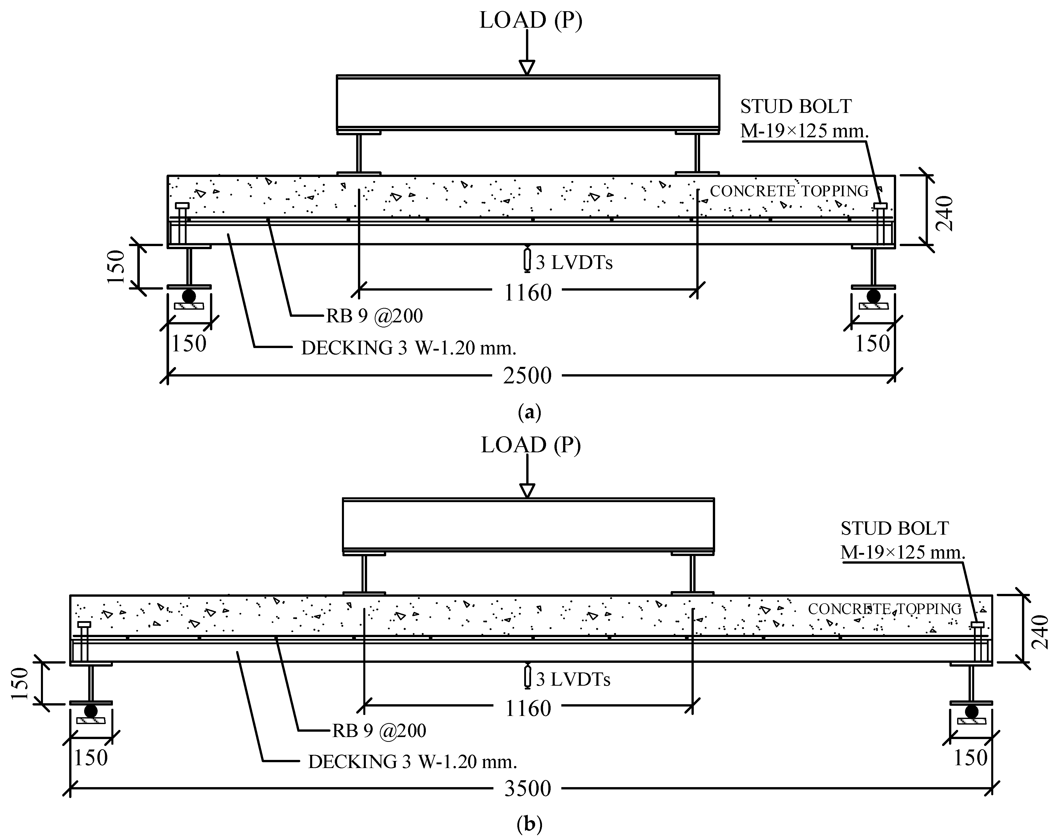
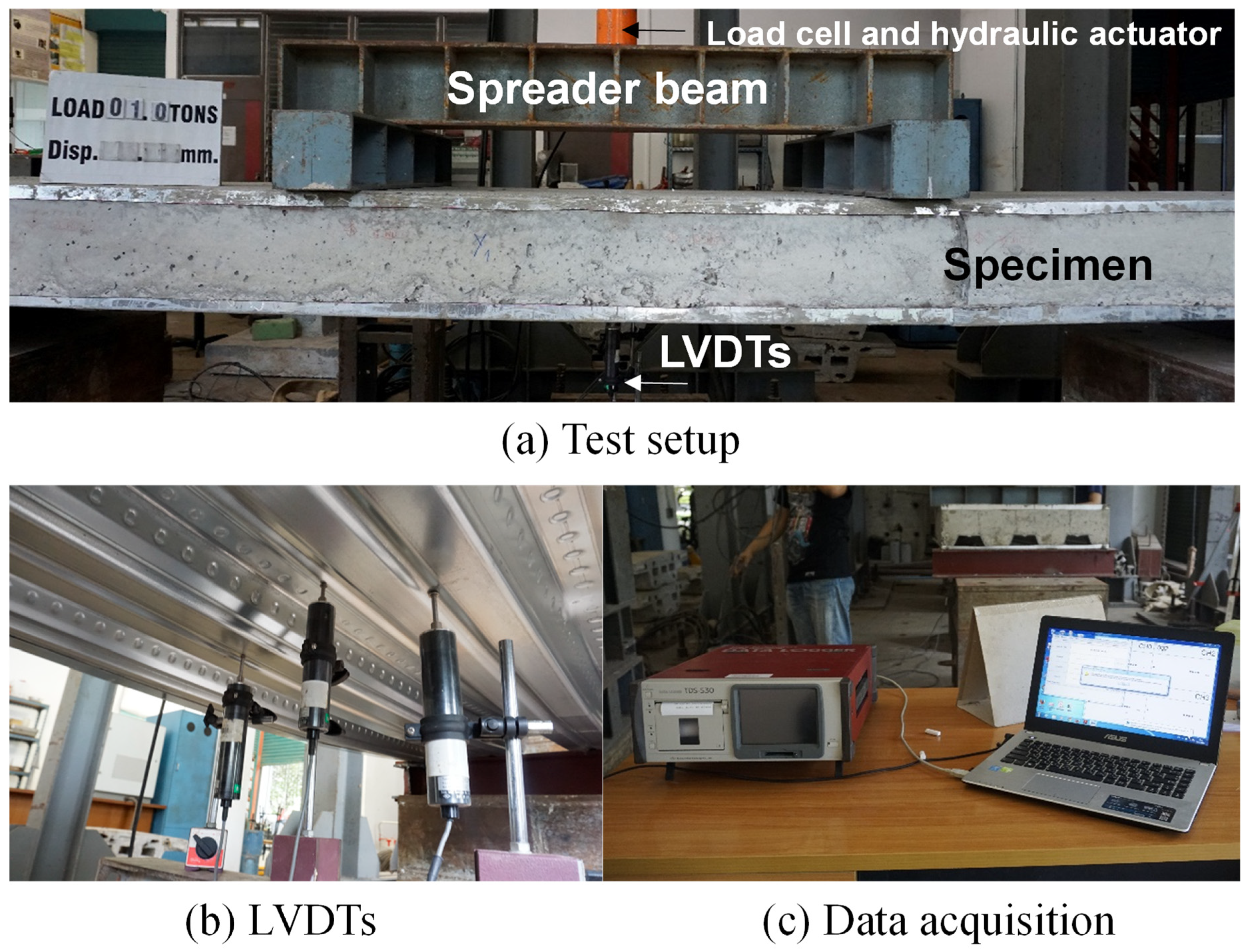
2.2. Test Setup and Instrumentation

In order to investigate the flexural behaviors, the load and displacement of the simply supported composite decks were monitored during the tests. Figure 3a shows the scheme for the four-point bending tests of specimens S1 and S2. Figure 3b demonstrates the scheme for the four-point bending tests of specimens S3 and S4. To reflect the actual composite deck‒beam joints, the supports of the decks were I-shaped section steel beams. The profile steel sheets were connected to the I-steel beams via the studs, as demonstrated in Figure 3a,b. Three linear variable differential transformers (LVDT) were placed at the bottom midspan of the composite deck along the deck width to measure the deflection. A load cell with a capacity of 50 tons and a hydraulic jack were installed on the top of the specimen to record the applied loads. The loading was gradually applied in the vertical direction on the steel spreading beam for transferring the forces to the decks. The load control was set to 10 kN/min until failure. All sensors were connected to a data acquisition device, which was controlled by a computer, for processing the results. Figure 4a–c shows the photos of the actual test setup for a representative composite deck.

3. Results and Discussion

The experimental results are presented in terms of load–midspan deflection curves, crack patterns, and failure modes.

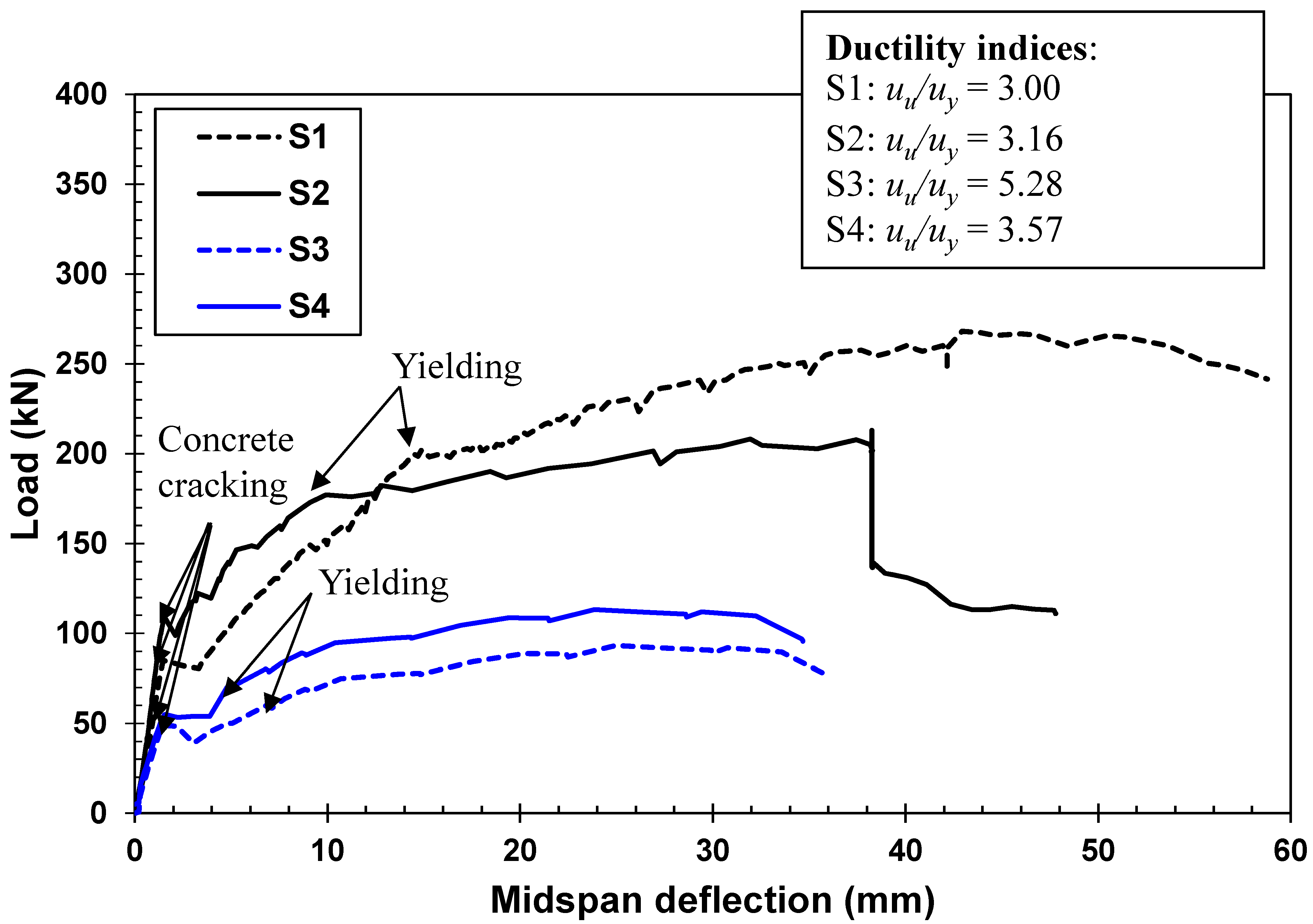
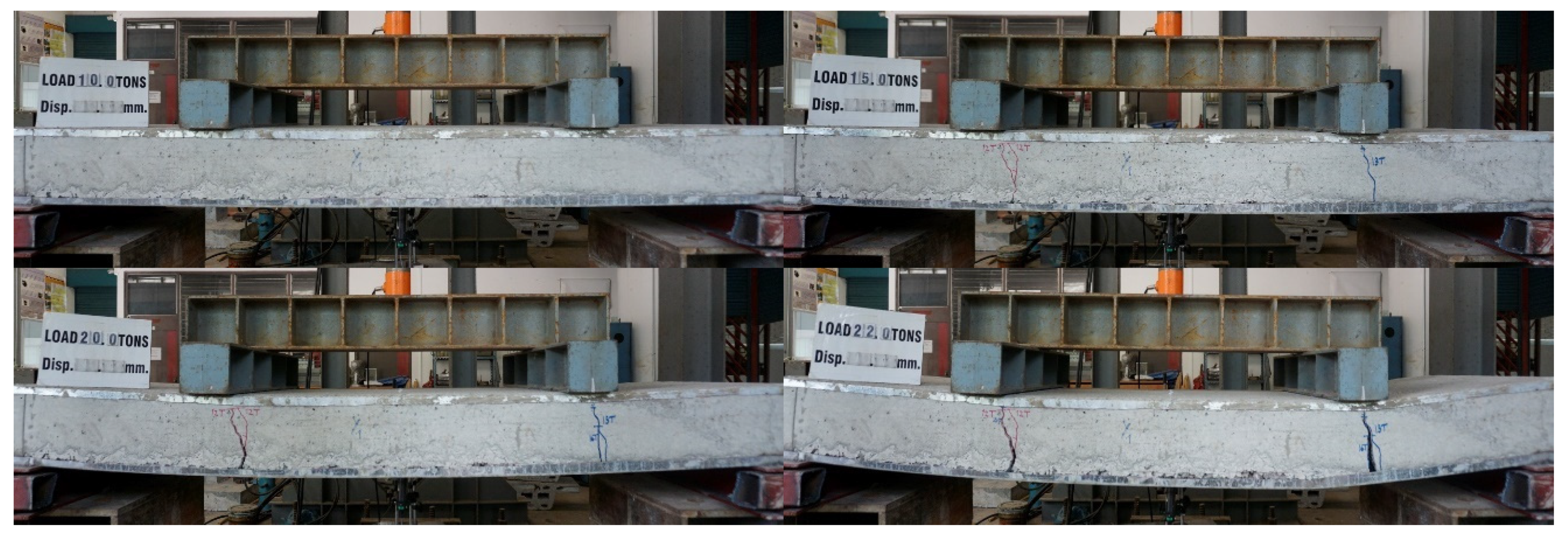
3.1. Load and Midspan Deflection Relationship

Figure 5 presents the relationships between the load and deflection for all tested composite decks. Overall, the specimens with a smaller shear span were stiffer than the decks with a larger shear span. This implies that the stiffness of the steel–concrete composite decks increased with the decrease of the shear span-to-depth ratios. In addition, the behavior of all tested decks were simply categorized into two stages: (1) before concrete cracking and (2) after concrete cracking. Before cracking, the composite decks behaved as the elastic members, in which the load–deflection curves demonstrated linearity. In this stage, no bond degradation between the steel profile sheet and concrete was observed. On the other hand, the load–deflection curves became nonlinear. In other words, the deflection no longer remained proportional to the applied load after initiation of the first crack, which took place in the flexure. This occurred because the concrete material broke immediately after the first cracking, while the steel reinforcement and sheet carried the entire load of the composite deck. In particular, local bond deterioration was observed at high loads.
The cracking loads, maximum loads, and deflections at peak forces of all tested composite decks are summarized in Table 2. The cracking loads of the composite decks S1 and S2 were 79.8 and 108.3 kN, respectively, while their maximum loads were 268.1 and 213.0 kN, respectively. The midspan deflection at the peak loads of composite decks S1 and S2 was 42.9 and 38.2 mm, respectively. It can be seen that despite the features of the S1 specimen are the same as those of the S2 specimen, the cracking loads, peak forces, and deflections at peaks are different. This could be because the arch action might be dominant in specimens S1 and S2 with a shear span-to-depth ratio of 2.5, ensuring that the force transfer could be partially carried by the concrete arch. The performance of the concrete arch may depend on the aggregate distribution and aggregate interlocking mechanism, which could be different between specimens S1 and S2. A similar phenomenon was reported in the study by Higuchi et al. [33]. Further discussion on the compressive arch action is shown in Section 3.2.
When the shear span-to-depth ratio was increased from 2.5 to 4.6, the ability of the composite to resist the applied load decreased. The first crack load and peak load of composite decks S3 and S4 were lower than those of the S1 and S2 specimens. However, the cracking moments were similar for all specimens. This was mainly because despite the much longer members of the series II specimens (S3/S4) compared with the series I specimens (S1/S2), the compressive strength and the sections of the concrete members were approximately the same for the two concrete series. The maximum moments and deflections at peak loads of the series I specimens increased by 21% and 40%, respectively, compared to those produced by the series II specimens. These results indicated that the shear span-to-depth ratio influenced the post-cracking behavior of the steel-concrete composite decks.
Table 2 presents the results of the nominal moments of composite decks derived by section analysis. The section analysis was carried out using conventional bending theory, which is commonly used to analyze the flexural behavior of conventional steel-reinforced concrete members [34]. The symbols used in the simplified section analysis are shown in Figure 6. The following assumptions were considered in the calculation. The linear strain distribution through the deck depth was examined. A perfect bond between steel and concrete was assumed. No tensile strength of concrete was included in the calculation. The equivalent concrete stress block for estimating the concrete internal force in compression was considered. Only the case with a neutral axis located beyond the steel profile sheeting was assumed. The formulation of the moment capacity after assuming force equilibrium in the section can be generally expressed as below:
M n = F a ( d a 2 ) + F d ( d a 2 )
F a = { E a ε a A a ; ε a < ε y a f y a A a       ; ε a ε y a
F d = { E d ε d A d ; ε a < ε y a f y d A d       ; ε a ε y a
where Mn is the moment capacity (N-mm); Fa and Fd denote the internal forces in steel sheet and reinforcement (N), respectively; a (= β1 × c) is the height of an equivalent block of concrete compressive stress distributed in the section (mm); β1 is the factor relating the depth of the equivalent rectangular compressive stress block to the depth of the neutral axis. The value of β1 was equal to 0.80 in this study [34]; c is the distance from the extreme compression fiber to the neutral axis (mm); d and d’ are the distances from top fiber to centroid of the steel sheet and reinforcement (mm), respectively.
The predicted results from section analysis generally overestimated the experimental results. This is possibly because the effect of the shear span-to-depth was not considered in the analysis and a perfect bond between the steel and concrete was assumed. This implies that further study on the model for prediction of the flexural capacity of the steel‒concrete composite decks is needed.
As shown in Figure 5, the ductility index is defined by the ratio between the displacement at peak load (uu) to the displacement at yielding (uy). It is important to note that the yielding point is given by a point on the curve corresponding to a change in stiffness of the composite, where the slope of the curve is distinct, since it is not possible to directly determine the strain of the composite [35,36]. The ductility indices of specimens S1 (uu/uy = 3.0) and S2 (uu/uy = 3.16) were lower than those of specimens S3 (uu/uy = 5.28) and S4 (uu/uy = 3.57). The decks with a short span length could form the shear arch action to induce the diagonal deformation but decrease the vertical deformation; consequently, the displacement at yielding load was nearer the displacement at peak load compared with the decks with a larger span length.

3.2. Crack Pattern and Mode of Failure

Figure 7a and Figure 8 show the crack patterns of the specimens under the load increments. Deck S1 started cracking at a load of 100 kN, while deck S3 began fracturing at a load by 130 kN. Generally, the specimens started cracking in the center; then, the cracks tended to open, and a new crack formation under the loading points was observed. In specimen S1 with a short shear span length, the cracks occurred in the pure bending region, while the cracks under the loading points were observed on deck S3 with a larger shear span length. In addition, at high loads, there were fewer cracks in the composite deck S3 than in deck S1. As observed from the tests, the failure crack width in specimen S3 was larger than that in deck S1. The possible reason is that besides the flexural capacity, the concrete arch (as illustrated in Figure 7b) in the shear span of deck S1 contributed to resisting the applied forces. The arch action in the deck S3 could be neglected, and it behaved only as a bending member; therefore, the flexural cracks were wide. These findings indicate that the shear span-to-depth ratio affected the failure mechanisms of the composite decks.
Figure 9 shows a typical failure mode for all test specimens. The primary failure mode observed in the experiments was the debonding of the sheeting profile steel and the detachment of the steel sheet from concrete followed by concrete fracture. The separation mode of failure between the steel sheet and concrete occurred because these test specimens lacked continuity. This failure mode revealed that the slippage of the steel sheet to concrete would govern the structural efficiency of the steel‒concrete composite decks. Indeed, the bond degradation between steel and concrete might accelerate the concrete deformation. Further, it can be recognized that the failure criteria assumed in the section analysis satisfied the actual failure except for the detachment of the profile sheeting steel from the concrete.

4. Conclusions

Experimental results on the mechanical behaviors of steel-concrete composite decks with various shear span-to-depth ratios, which were provided in previous studies with little information, were presented in this paper. The structural responses of four composite decks with shear span-to-depth ratios of 2.5 and 4.6 were experimentally and analytically identified. The major conclusions drawn from this study are as follows:
  • The stiffness, the cracking load, and the load-carrying capacity of the steel‒concrete composite decks increased with the decrease of the shear span-to-depth ratio. However, the composite decks with a longer shear span could provide greater displacement ductility.
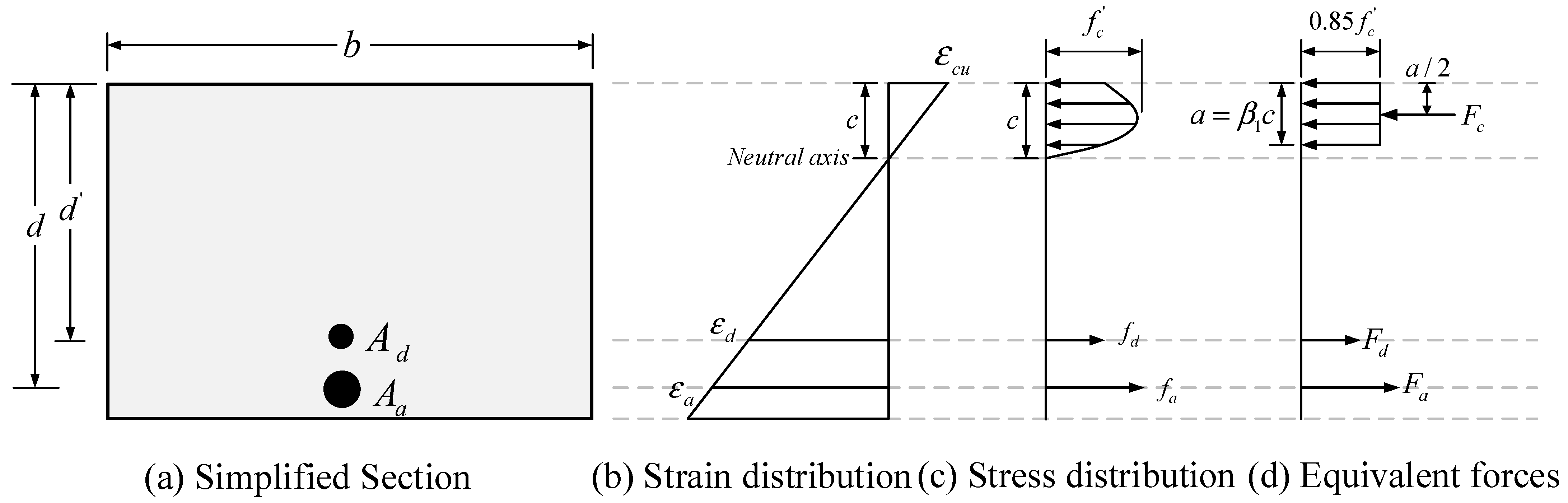
  • The current research found that the flexural strength of the composite decks predicted by conventional section analysis overestimated the experimental values, which is critical for safety. Therefore, in future, experimental, numerical, and analytical investigations should be conducted to comprehensively develop the strength model for composite decks.
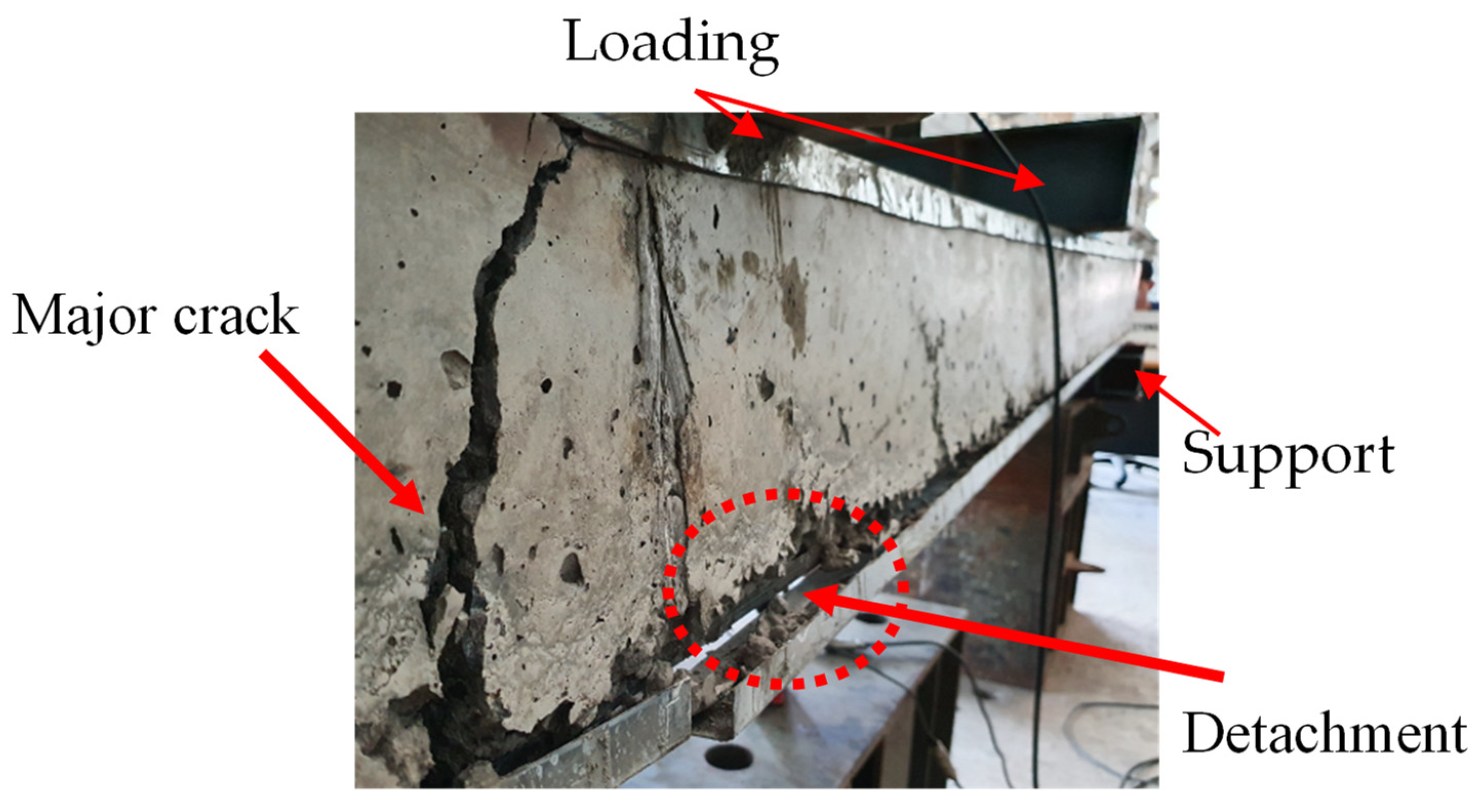
  • The shear span-to-depth ratio noticeably affected the failure mechanism of the steel‒concrete composite decks. The flexural cracks concentrated in the pure bending region were observed in the specimen with a shear span-to-depth ratio of 2.5. The specimen with a shear span-to-depth ratio of 4.6 showed the flexural cracks distributed under loading areas. It should be noted that the longer shear span length, the larger the flexural cracks observed in the composite deck.
  • At failure completion, the detachment of profile sheeting steel to concrete was observed. A measurement of the bond‒slip profile between the steel sheet and concrete is needed. An on-going study on innovative anchorage and friction systems to prevent the slippage between steel and concrete in the composite slabs is planned by the authors.
  • This study might serve as a source for the initial design of steel‒concrete composite slabs regarding the shear span-to-depth ratios.

Author Contributions

Conceptualization, S.S., C.T. and S.K.; methodology, S.S., C.T. and S.K.; validation, S.S., C.T. and S.K.; formal analysis, S.S., C.T. and S.K.; investigation, S.S., C.T. and S.K.; resources, P.N., P.J. and E.N.F.; data curation, W.D.; writing—original draft preparation, C.T., S.K., P.N., P.J. and L.V.H.B.; writing—review and editing, S.S., C.T., S.K., P.N., P.J. and L.V.H.B.; visualization, S.S., C.T. and S.K.; supervision, S.S. and E.N.F.; project administration, S.S. and P.J.; funding acquisition P.N., P.J. and E.N.F. All authors have read and agreed to the published version of the manuscript.

Funding

This work was supported by the Thammasat University Research Unit in Structural and Foundation Engineering.

Institutional Review Board Statement

Not applicable.

Informed Consent Statement

Not applicable.

Data Availability Statement

The data and materials in this paper are available.

Acknowledgments

The authors would like to acknowledge the Lertloy Metal Sheet Company for supplying composite materials and the assistance with the specimen-casting process. All individuals have consented to the acknowledgement.

Conflicts of Interest

The authors declare no conflict of interest.

References

  1. Allen, D. History of Cold Formed Steel. 2006. Available online: http://www.structuremag.org (accessed on 10 May 2021).
  2. Canadian Sheet Steel Building Institute (CSSBI). Roof Deck and Composite Floor Deck. 2020. Available online: https://cssbi.ca/products/roof-deck-composite-floor-deck/ (accessed on 15 May 2021).
  3. Avudaiappan, S.; Flores, E.I.S.; Araya-Letelier, G.; Thomas, W.J.; Raman, S.N.; Murali, G.; Amran, M.; Karelina, M.; Fediuk, R.; Vatin, N. Experimental investigation on composite deck slab made of cold-formed profiled steel sheeting. Metals 2021, 11, 229. [Google Scholar] [CrossRef]
  4. Gholamhoseini, A.; Gilbert, R.; Bradford, M.; Chang, Z. Longitudinal shear stress and bond–slip relationships in composite concrete slabs. Eng. Struct. 2014, 69, 37–48. [Google Scholar] [CrossRef]
  5. Akhand, A.; Badaruzzaman, W.W.; Wright, H. Combined flexure and web crippling strength of a low-ductility high strength steel decking: Experiment and a finite element model. Thin-Walled Struct. 2004, 42, 1067–1082. [Google Scholar] [CrossRef]
  6. Crisinel, M.; Marimon, F. A new simplified method for the design of composite slabs. J. Constr. Steel Res. 2004, 60, 481–491. [Google Scholar] [CrossRef]
  7. Kim, H.-Y.; Jeong, Y.-J. Ultimate strength of a steel–concrete composite bridge deck slab with profiled sheeting. Eng. Struct. 2010, 32, 534–546. [Google Scholar] [CrossRef]
  8. Mohammed, B.S.; Al-Ganad, M.A.; Abdullahi, M. Analytical and experimental studies on composite slabs utilising palm oil clinker concrete. Constr. Build. Mater. 2011, 25, 3550–3560. [Google Scholar] [CrossRef]
  9. Prajapati, K.K.; Vanza, M.G.; Vakil, M.D. Behavior of cold-formed stainless steel composite deck. Int. J. Earth Sci. Eng. 2011, 4, 616–618. [Google Scholar]
  10. Baskar, R.; Jeyasehar, C.A. Experimental and numerical studies on composite deck slabs. Int. Eng. Res. Dev. 2012, 3, 22–32. [Google Scholar]
  11. Hedaoo, N.; Gupta, L.M.; Ronghe, G.N. Design of composite slabs with profiled steel decking: A comparison between experimental and analytical studies. Int. J. Adv. Struct. Eng. 2012, 4, 1. [Google Scholar] [CrossRef] [Green Version]
  12. Abdullah, R.; Easterling, W.S. New evaluation and modeling procedure for horizontal shear bond in composite slabs. J. Constr. Steel Res. 2009, 65, 891–899. [Google Scholar] [CrossRef] [Green Version]
  13. Chen, S. Load carrying capacity of composite slabs with various end constraints. J. Constr. Steel Res. 2003, 59, 385–403. [Google Scholar] [CrossRef]
  14. Eldib, M.A.-H.; Maaly, H.; Beshay, A.; Tolba, M. Modelling and analysis of two-way composite slabs. J. Constr. Steel Res. 2009, 65, 1236–1248. [Google Scholar] [CrossRef]
  15. Chen, S.; Shi, X. Shear bond mechanism of composite slabs—A universal FE approach. J. Constr. Steel Res. 2011, 67, 1475–1484. [Google Scholar] [CrossRef]
  16. Marimuthu, V.; Seetharaman, S.; Jayachandran, S.A.; Chellappan, A.; Bandyopadhyay, T.; Dutta, D. Experimental studies on composite deck slabs to determine the shear-bond characteristic values of the embossed profiled sheet. J. Constr. Steel Res. 2006, 63, 791–803. [Google Scholar] [CrossRef]
  17. European Committee for Standardization. Design of Composite Steel and Concrete Structures—General Rules and Rules for Buildings; EN 1994: Part 1. 2003. Available online: http://www.phd.eng.br/wp-content/uploads/2015/12/en.1992.1.1.2004.pdf (accessed on 15 May 2021).
  18. BSI-BS 5950-4. Use of Steelwork in Building—Code of Practice for Design of Composite Slabs with Profiled Steel Sheeting; BS 5950: Part 4; British Standards Institution (BSI): London, UK, 1994; Available online: https://www.ihsti.com/CIS/document/83107 (accessed on 15 May 2021).
  19. Baskar, R. Experimental and numerical studies on composite deck slabs. Int. J. Eng. Technol. 2012, 2, 1116–1125. [Google Scholar]
  20. Lakshmikandhan, K.N.; Sivakumar, P.; Ravichandran, R.; Jayachandran, S.A. Investigations on efficiently interfaced steel concrete composite deck slabs. J. Struct. 2013, 2013, 628759. [Google Scholar] [CrossRef] [Green Version]
  21. Siva, A.; Senthil, R.; Saddam, M.A. Experimental investigation on longitudinal shear behaviour of steel concrete composite deck slab. J. Struct. Eng. 2016, 43, 445–453. [Google Scholar] [CrossRef]
  22. Siva, A.; Swaminathan, S.; Prasanth, K.; Senthil, R. Experimental investigation of trapezoidal profile sheeting under varying shear spans. Appl. Mech. Mater. 2016, 845, 148–153. [Google Scholar] [CrossRef]
  23. Sheet, I.S.; Ahmed, S.M.; Avudaiappan, S.; Flores, E.I.S.; Chandra, Y.; Astroza, R. Shear bond behaviour of elemental composite beams with different configurations. Eng. Struct. 2019, 201, 109742. [Google Scholar] [CrossRef]
  24. Ahmed, S.M.; Avudaiappan, S.; Sheet, I.S.; Flores, E.I.S.; Pina, J.C.; Yanez, S.J.; Guzmán, C.F. Prediction of longitudinal shear resistance of steel-concrete composite slabs. Eng. Struct. 2019, 193, 295–300. [Google Scholar] [CrossRef]
  25. Shirgaonkar, A.A.; Patil, Y.D.; Patil, H.S. Influence of stiffeners and pattern of shear screws on behaviour of cold formed profiled deck composite floor. Case Stud. Constr. Mater. 2021, 15, e00572. [Google Scholar] [CrossRef]
  26. Lim, S.-S.; Wong, J.-Y.; Yip, C.-C.; Pang, J.-W. Flexural strength test on new profiled composite slab system. Case Stud. Constr. Mater. 2021, 15, e00638. [Google Scholar] [CrossRef]
  27. Hu, B.; Wu, Y.-F. Effect of shear span-to-depth ratio on shear strength components of RC beams. Eng. Struct. 2018, 168, 770–783. [Google Scholar] [CrossRef]
  28. Shahnewaz, M.; Rteil, A.; Alam, M.S. Shear strength of reinforced concrete deep beams – A review with improved model by genetic algorithm and reliability analysis. Structures 2019, 23, 494–508. [Google Scholar] [CrossRef]
  29. Londhe, R. Shear strength analysis and prediction of reinforced concrete transfer beams in high-rise buildings. Struct. Eng. Mech. 2011, 37, 39–59. [Google Scholar] [CrossRef] [Green Version]
  30. Ashour, A.F. Shear capacity of reinforced concrete deep beams. J. Struct. Eng. 2000, 126, 1045–1052. [Google Scholar] [CrossRef]
  31. Chiu, C.-K.; Ueda, T.; Chi, K.-N.; Chen, S.-Q. Shear crack control for high strength reinforced concrete beams considering the effect of shear-span to depth ratio of member. Int. J. Concr. Struct. Mater. 2016, 10, 407–424. [Google Scholar] [CrossRef] [Green Version]
  32. ACI Committee 211.4R; Guide for Selecting Proportions for High-Strength Concrete Using Portland Cement and Other Cementitious Materials; American Concrete Institute Pubs: Farmington Hills, MI, USA, 2008.
  33. Higuchi, K.; Iwama, K.; Maekawa, K. Remaining shear capacity of fire-damaged high strength RC beams after moist curing. J. Adv. Concr. Technol. 2021, 19, 897–912. [Google Scholar] [CrossRef]
  34. ACI Committee 318-19; Building Code Requirements for Structural Concrete and Commentary; American Concrete Institute: Farmington Hills, MI, USA, 2019.
  35. Thongchom, C.; Lenwari, A.; Aboutaha, R.S. Effect of sustained service loading on post-fire flexural response of reinforced concrete T-beams. ACI Struct. J. 2019, 116, 243–254. [Google Scholar] [CrossRef]
  36. Lenwari, A.; Thongchom, C.; Aboutaha, R.S. Cyclic flexural performance of fire-damaged reinforced concrete beams strengthened with carbon fiber-reinforced polymer plates. ACI Struct. J. 2020, 117, 133–146. [Google Scholar] [CrossRef]
Figure 1. Details of test composite decks. (a) Specimens S1 and S2 (dimensions in mm). (b) Specimens S3 and S4 (dimensions in mm).
Buildings 11 00624 g001
Figure 2. Casting of specimens.
Buildings 11 00624 g002
Figure 3. Test setup of composite deck. (a) Specimens S1 and S2 (dimensions in mm). (b) Specimens S3 and S4 (dimensions in mm).
Buildings 11 00624 g003
Figure 4. Test setup and instrumentation for testing the composite deck. (a) Installation of a representative beam for test preparation. (b) Positions of LVDTs. (c) Monitoring system.
Buildings 11 00624 g004
Figure 5. Load-displacement curves of tested composite decks.
Buildings 11 00624 g005
Figure 6. Section analysis of composite decks.
Buildings 11 00624 g006
Figure 7. Crack mechanism of specimen S1: (a) crack progression; (b) demonstration of compressive arch action.
Buildings 11 00624 g007
Figure 8. Crack patterns of specimen S3.
Buildings 11 00624 g008
Figure 9. Failure mode of the deck (Specimen S2).
Buildings 11 00624 g009
Table 1. Dimensions and shear span-to-depth ratio of composite decks.
SeriesSpecimen No.Width (mm)Depth (mm)Length (mm)Span Length (mm)Shear Span (mm)Shear Span-to-Depth (a/h)
IS11000240250023505952.5
S21000240250023505952.5
IIS310002403500335010954.6
S410002403500335010954.6
Table 2. The experimental results of the tested composite decks.
SeriesSpecimen
No.
Cracking Load
(kN)
Cracking Moment
(kN-m)
Maximum
Load
(kN)
Maximum Moment
(kN-m)
Maximum Moment by Section Analysis (kN-m)Difference in Maximum Moment (%)Deflection at Peak Load
(mm)
Failure Mode
IS179.823.7268.179.865.218.342.9SD-CF *
S2108.332.221363.465.22.838.2SD-CF
IIS350.727.893.175165.227.825SD-CF
S45530.1113.176265.25.223.9SD-CF
Note: * SD-CF = profile sheeting steel debonding followed by concrete fracture.
Publisher’s Note: MDPI stays neutral with regard to jurisdictional claims in published maps and institutional affiliations.

