Article

Seismic Resistance of Timber Frames with Mud and Stone Infill Walls in a Chinese Traditional Village Dwelling

1
Faculty of Architecture, Civil and Transportation Engineering, Beijing University of Technology, Beijing 100124, China
2
Beijing Institute of Housing and Urban-Rural Construction Science and Technology, Beijing 101160, China
3
Research Institute of Wood Industry, Chinese Academy of Forestry, Beijing 100091, China
4
School of Civil and Transportation Engineering, Beijing University of Civil Engineering and Architecture, Beijing 100044, China
*
Author to whom correspondence should be addressed.
Buildings 2021, 11(12), 580; https://doi.org/10.3390/buildings11120580
Submission received: 22 October 2021 / Revised: 18 November 2021 / Accepted: 22 November 2021 / Published: 25 November 2021

Abstract

:
Traditional Chinese wood residences consist of timber frames with masonry infill walls or other types of infill, representing valuable heritage. A field investigation of traditional village dwellings in northern China consisting of timber frames with mud and stone infill walls was conducted. Their construction characteristics are reported, and static cyclic tests were performed on two full-size wood-stone hybrid walls with different configurations (exterior transverse wall and internal transverse wall) and no openings (doors or windows). Their failure mechanics and seismic capacity, i.e., the strength, stiffness, ductility, and energy dissipation, were investigated. The results are compared with a previous experimental study of two full-size timber frames with the same traditional structure but no infill to determine the effect of the mud and stone infill on the lateral resistance. The experimental results indicate that the stone infill has a critical influence on the lateral performance of traditional village buildings, resulting in a high lateral stiffness, high strength (>20 kN), and a high ductility ratio (>10). An increase in the vertical load leads to an increase in the lateral resistance of the timber frame with infill walls, larger for the internal transverse wall than the external gable wall. The incompatibility of the deformation between the timber frame and stone infill is the main failure reason, resulting in falling stones and collapse with undamaged timber frames. Suggestions are provided for the protection and repair of traditional wood residences in northern China.

1. Introduction

Traditional village houses are examples of folk architecture and were constructed by local craftsmen using traditional techniques based on regional characteristics. Traditional village dwellings are important aspects of culture and civilization. They preserve the historical memory of the nation, folk wisdom, the way of life of local people, and represent the art and culture of different ethnic regions. Wood buildings consisting of timber frames with masonry infill walls or other types of infill are typical traditional village residences, representing a valuable heritage.
Wood was the dominant material used when architectural civilization began in China [1]. Timber structures with flexible mortise-tenon joints are typical in old traditional residence dwellings and official palaces [2]. Numerous studies focused on timber frame construction and mortise-tenon connections in the last decade. Chun et al. [3] investigated the seismic performance of timber frames with various mortise-tenon joints in official buildings in southern China. Li et al. [4,5] carried out experimental studies on the seismic performance of a double-span traditional timber frame with dovetail connections, using a three-column timber frame palace from the Chinese Song Dynasty as the prototype. Xie et al. [1] analyzed the effect of different column heights and vertical loads on the lateral behavior of traditional Chinese timber frame buildings and provided an analytical model. Li et al. [6] investigated the damaging effect of a one-way straight mortise-tenon joint on the seismic performance of wooden frame structures. Shen et al. [7] conducted pseudo-static cyclic loading tests of three full-scale timber frame specimens based on a prototype to understand the seismic performance of traditional village residences in northern China consisting of a post-and-lintel timber frame. Experimental studies were conducted by Yao et al. [8], Sui et al. [9], and Gao et al. [10] in addition to a seismic study of mortise-tenon connections [11,12,13,14,15]. The study on Chuan-Dou timber residences in southern China indicates that a timber frame with infilled timber panel and plentiful Chuan Fang, Dou Fang and Dijiao Fang are resilient enough so they protect the lives of the inhabitants [16,17,18,19]. However, very few studies on the seismic performance of wood-frame buildings with masonry infill walls were conducted, especially the rubble infill walls commonly used in Chinese traditional village houses.
Wood frames with stone, earth, and brick infill were common in rural village and town buildings worldwide in the past, representing a traditional construction method in many countries (e.g., Portugal, Italy, Greece, Turkey, China, and Romania) [20,21,22,23,24,25,26]. Some timber-framed masonry (TFM) houses have survived earthquakes with little damage compared to poorly constructed reinforced concrete structures with masonry infill, such as the 1999 Kocaeli earthquake in Turkey [27], the 2003 Lefkada earthquake [28], and the 2010 Haiti earthquake [29,30]. The common construction method of a wood frame with diagonal bracing provides good confinement of stone and brick infill and ensures the good interaction between the timber frame and the infill. Examples of this construction method included the “Paianta” structure in Romania [31], the “Pombalino” structure in Portugal [32,33,34], the “Kay peyi” structure in Haiti [30], and the “Dhajji” structure in Kashmir, Pakistan, and India [35]. Dutu et al. [36] investigated the seismic performance of a timber frame structure connected with small half-cross joints and rectangular masonry infill panels (without diagonal bracings). The horizontal and vertical wood strips are equivalent to diagonal bracings and strengthen the cooperation work between the wood frame and infill structure. There is scarce study on the in-plane experimental behavior of stone masonry walls. Vasconcelos et al. [37] conducted static cyclic in-plane loading tests on dry stack regular cuboid stone masonry walls, walls with irregular stone units with cement mortar and rubble masonry walls with cement mortar.
However, traditional village residences in China are substantially different from structures in other parts of the world. In northern China, a common construction type of traditional residences consists of four beams and eight columns, as shown in Figure 1. This timber frame building has the following characteristics: (1) eight wood columns are supported by plinths or the ground without any fasteners. (2) Different mortise-tenon joints are used to connect the wood beams and columns without using nails, dowels, or other steel parts [38]. (3) The top of the structure is heavy, and the weight of the gable roof is transferred to the columns. (4) Stone, masonry, or earth infill is used inside the walls to stabilize the timber frame. As for the stone infill, the timber frame is generally embedded in thick mud and stone infill wall and ties the walls together. Unlike modern construction methods that use uniform rectangular bricks and cement mortar in village houses, the stones have various sizes. They were obtained locally and were joined together and embedded in the clay mud by experienced craftsmen. The traditional wood residences in villages have experienced different levels of damage, and many have been lost. Unfortunately, very few people still have the knowledge and experience to construct traditional village residences.
Due to the important heritage value of traditional village residences with a timber frame structure and infill walls, the tendency is to protect and repair such traditional village residences since they are part of China’s cultural identity. A study of the seismic performance of hybrid wood-stone structures improves our understanding of the existing traditional village houses and facilitates the repair, reinforcement, and protection of the historical and cultural heritage of traditional villages. In this study, field investigations of buildings with timber frames and mud and stone infill walls were conducted. Their construction characteristics were investigated, and static reversed cyclic loading tests were conducted on two full-scale transverse walls with the same features and different vertical loads at different positions. The failure modes and mechanics, load-displacement hysteresis curves, envelope curves, stiffness, strength, and energy dissipation of the hybrid structure were investigated. Subsequently, the seismic performance of the hybrid wood-stone walls was analyzed at different positions to reveal the effects of different vertical loads. Furthermore, the results were compared with the load-displacement curves of full-scale timber frames with no infill, as presented by Shen et al. [7] to determine the contribution of mud and stone infill on the lateral resistance. The goal of this study was to provide a fundamental understanding of the seismic performances of traditional village residences in northern China consisting of wood frames with mud and stone infill walls. The results provide references for the seismic assessment, protection, and repair of existing traditional village residences.

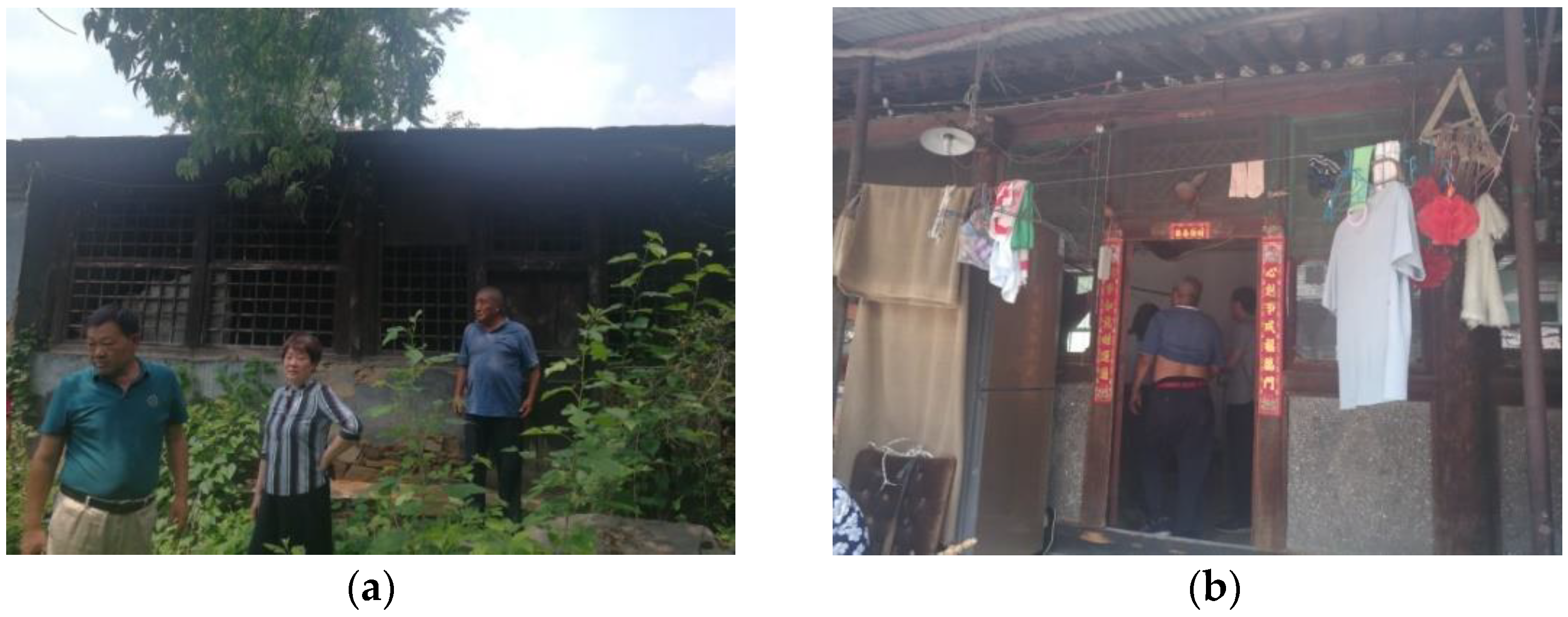
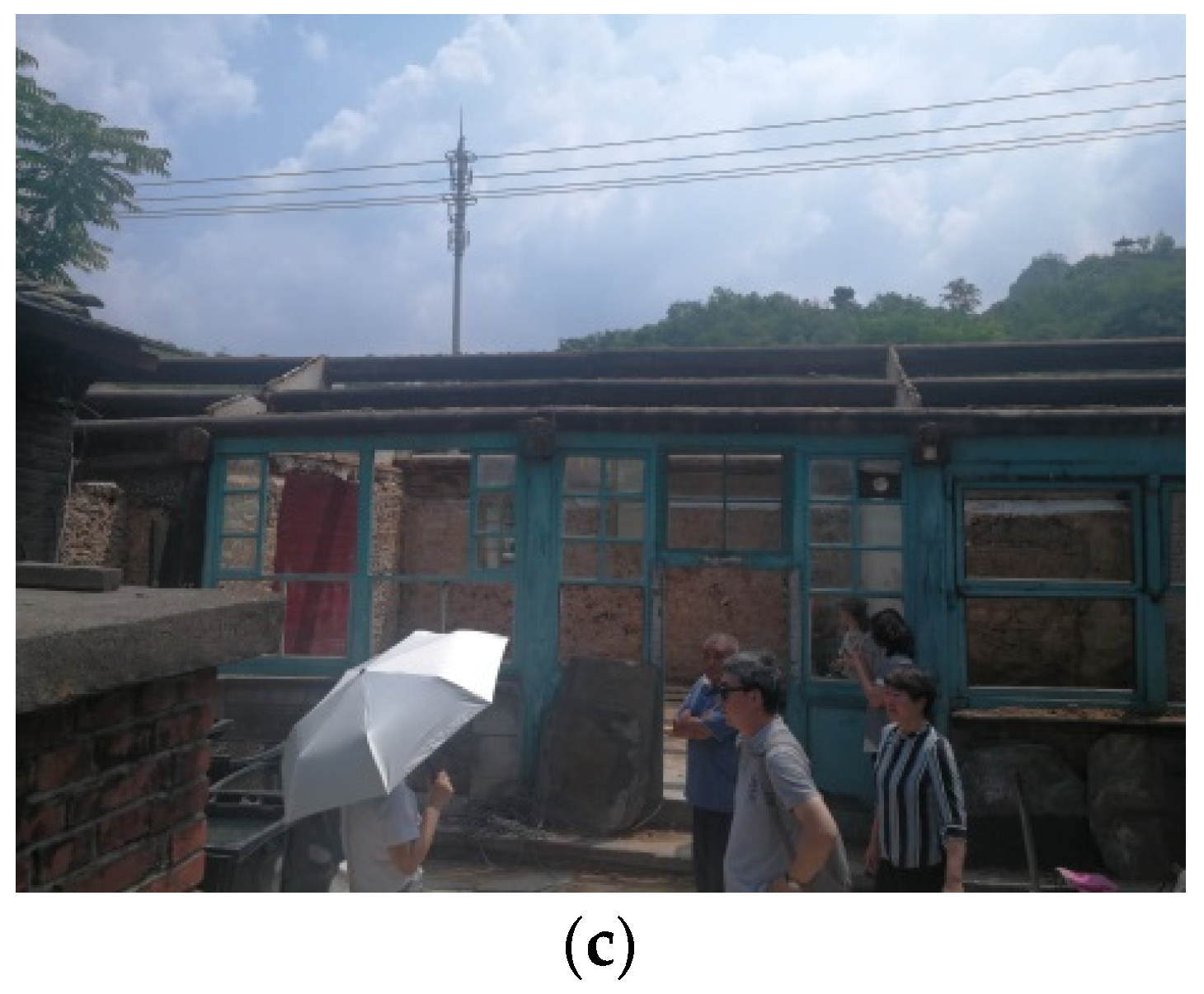
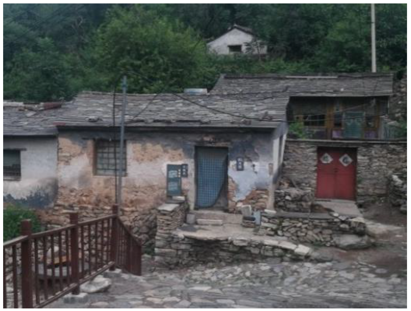
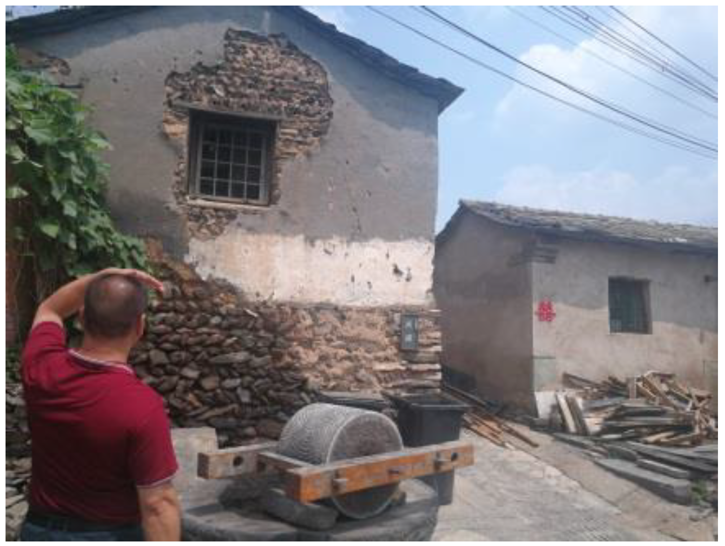
2. Field Investigations
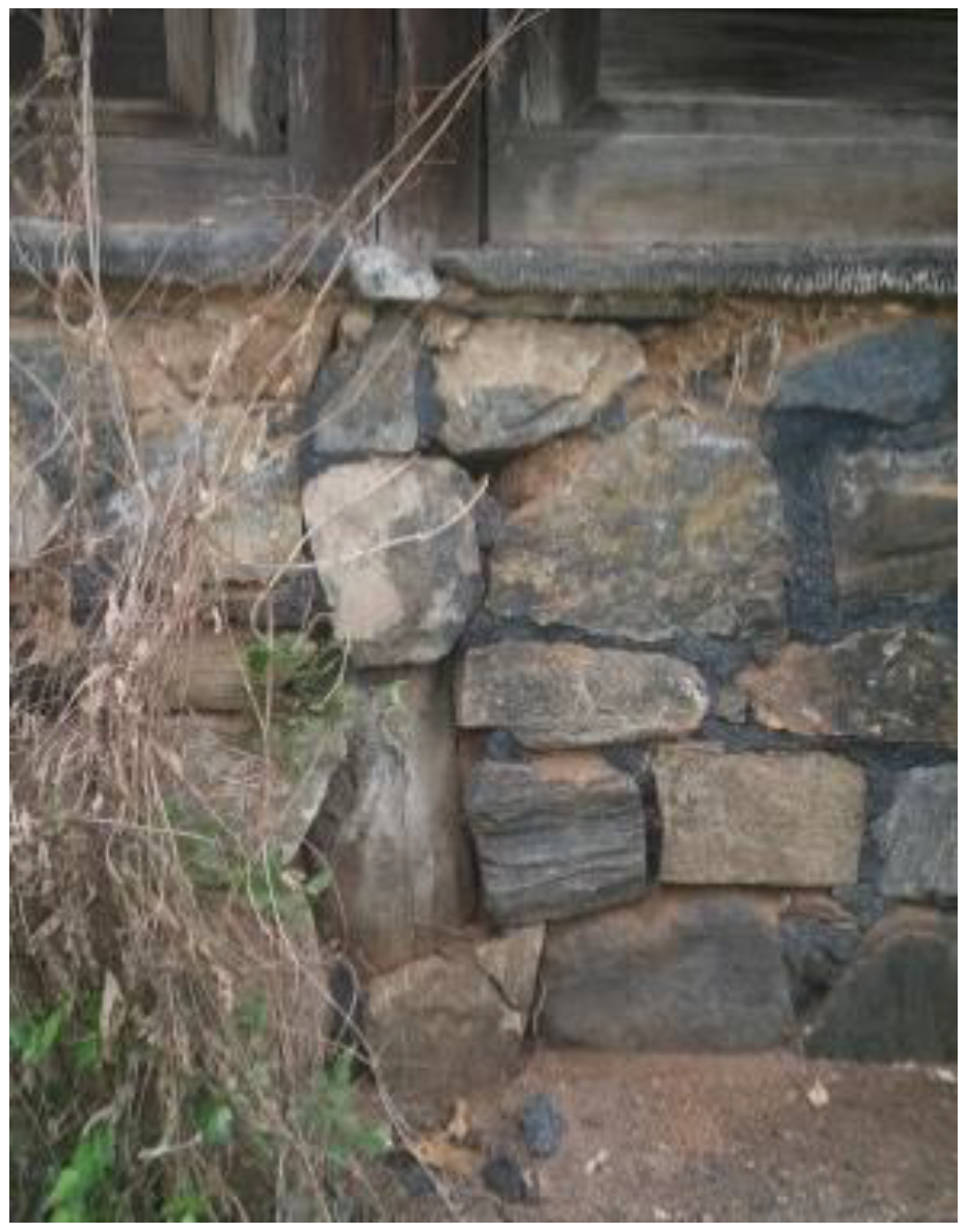
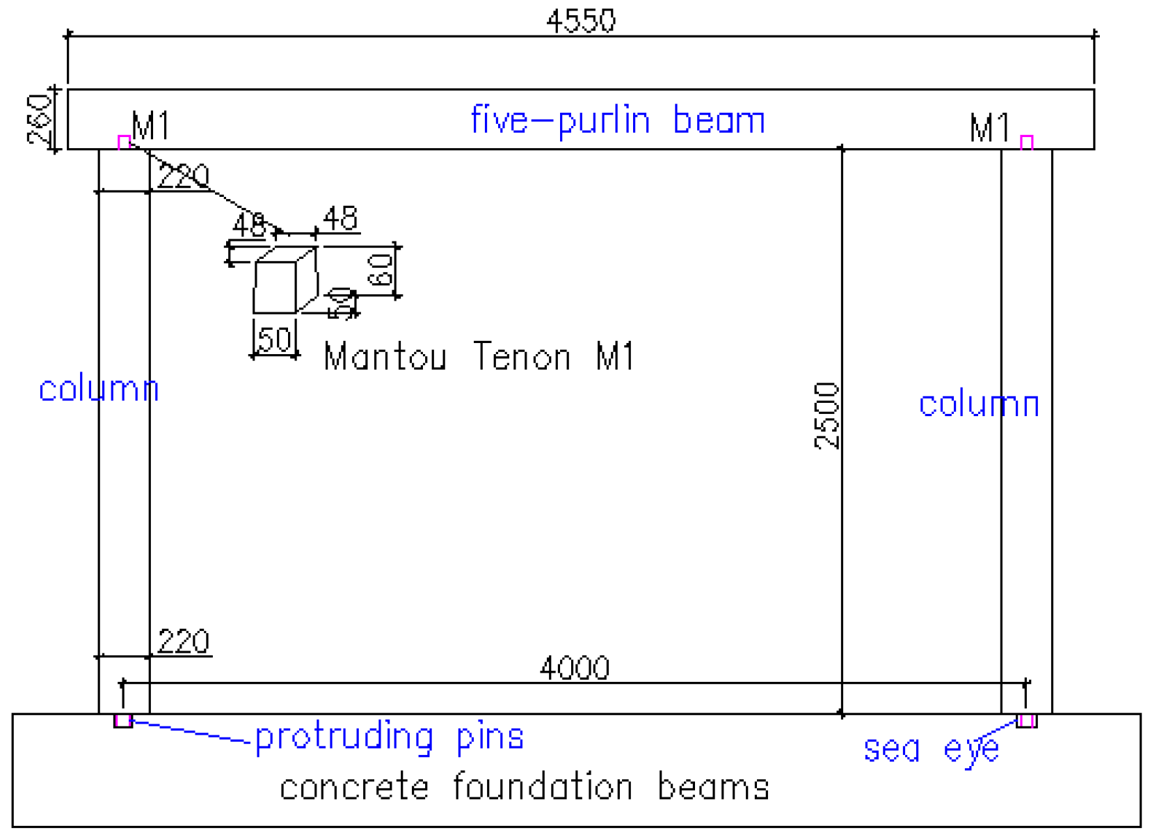
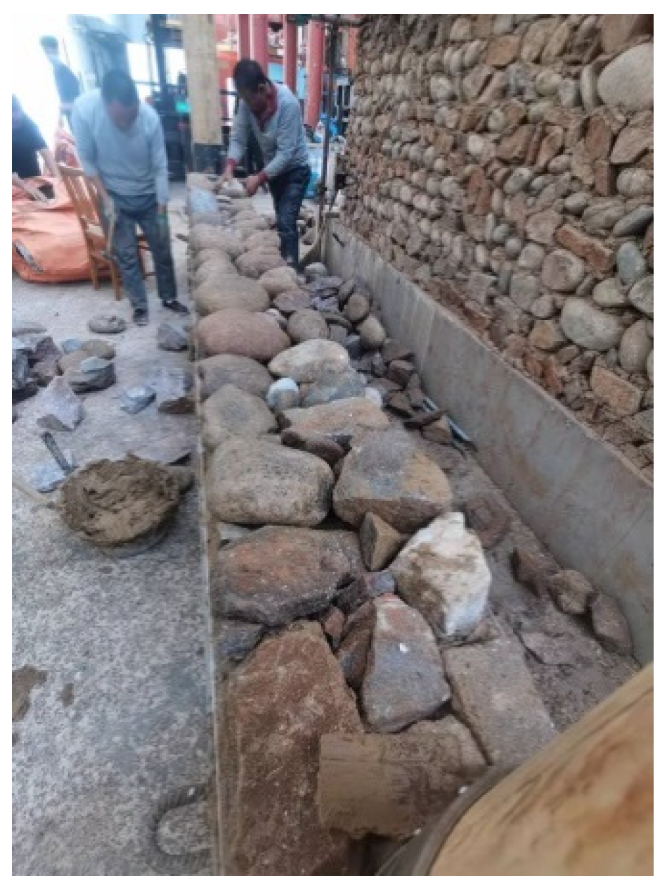
Several regions were selected for the field investigations of traditional wood-stone houses in the Fangshan district and Yanqing district nearby the mountain and hill regions in northern China. The majority of the old traditional buildings were of the “four beam and eight column” style and were constructed before the 1970s. Some buildings had been abandoned and suffered significant damage, and others were well maintained or had been repaired by the owners, as displayed in Figure 2. Most structures had problems, such as rotting of the timber frame, falling of the stone infill wall, and roof collapse.

2.1. Foundation

The old traditional village residences typically have stone foundations consisting of unprocessed rocks and rubble, such as river boulders and round, rectangular, and triangular rocks. The stones were generally layered without mortar or with little mud, forming a platform, as shown in Figure 3. The stone platform itself is a medium of seismic energy dissipation, either by gravitation or by the addition of clay mud, to achieve better adherence. It is probable to require some time to gravitationally distribute settle on the site, after completing laying up the foundation.

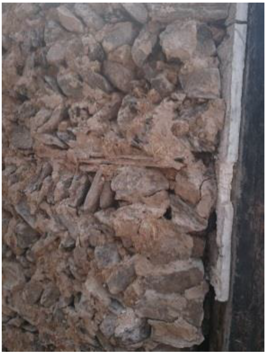
2.2. Structural Walls

The old traditional residences generally have three or four rooms with lengths of 3 m and 3.2 m; some residences of poor households may have two rooms. The width of the residences is between 3.9 m and 4.2 m. Figure 4 shows an external transverse wall made of mud and stone with a window. Some of the plaster on the wall has fallen off due to poor maintenance.
The timber columns have diameters of 220 mm to 250 mm. The horizontal beams called “five-purlin beam” connected to the columns are round or regularly shaped with cross-sections ranging from 250 mm to 280 mm. The beam and the columns are connected by Mantou mortise and tenon joints. Figure 5 shows two short columns, and a three-purlin beam and a king post are missing. Pinus sylvestris, dahurian larch, poplar, and ash were typically used for the timber frame.
The infill consists of layered stones mixed with mud, and the walls have a minimum thickness of 400 mm. However, no connectors are used to attach the infill wall to the timber frame, as shown in Figure 6. Water, soil, and straw are mixed and used to fill the space between the rocks, as illustrated in Figure 7. The quality of the mud mortar depends on the soil type. Soils containing a high amount of clay are preferred for construction due to their high cohesiveness and hardness. However, clay soils crack when they dry.

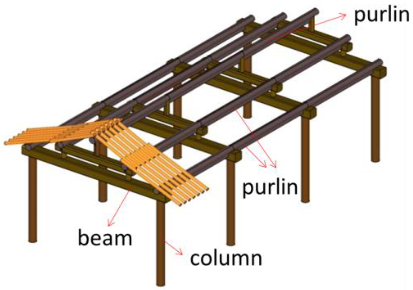
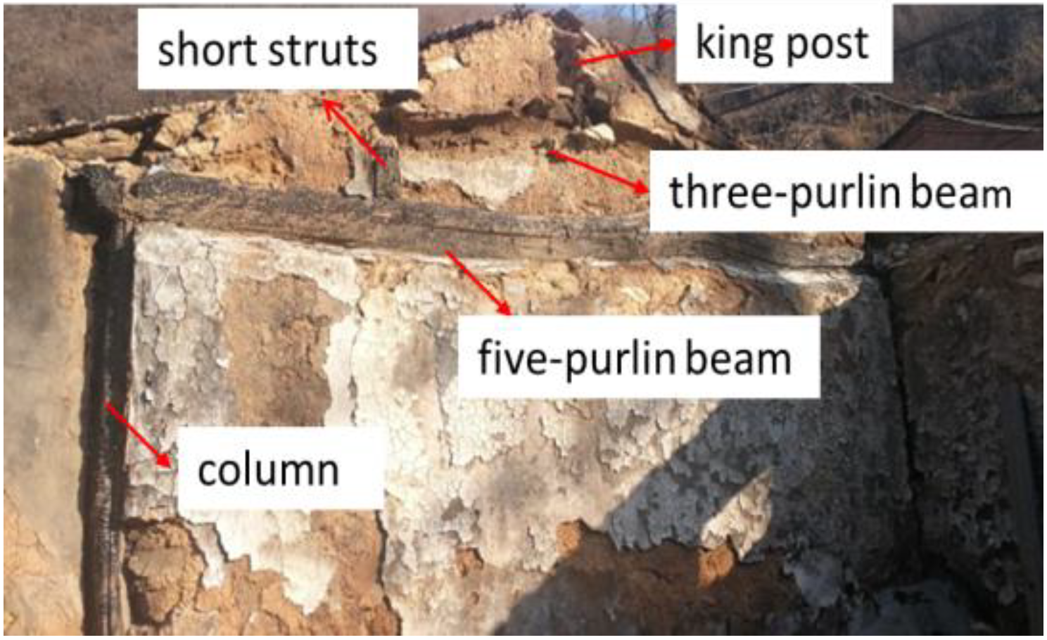
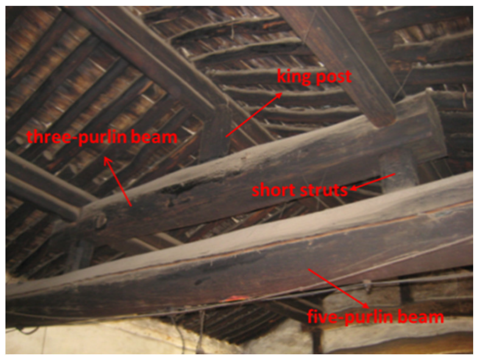
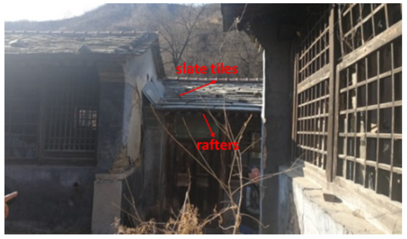
2.3. Roof Structure and Covering

A five-purlin flush-gable roof is typically used. The roof consists of a five-purlin beam, short struts, a three-purlin beam, and a king post from bottom to top to support the roof purlins (Figure 8). The traditional roof covering consists of rafters, reed matting, mud, and slate tiles from bottom to top. The rafters have diameters of 70 mm to 90 mm. A layer of reed matting on the rafters was covered by a mud layer with a thickness of about 10 mm. Since the local area is rich in stones, slate tiles are commonly used as roof coverings. They commonly have a thickness of 12 mm to 15 mm (Figure 9).

3. Experimental Program

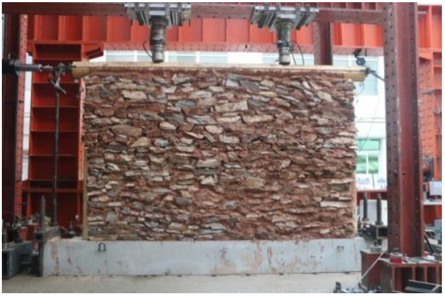
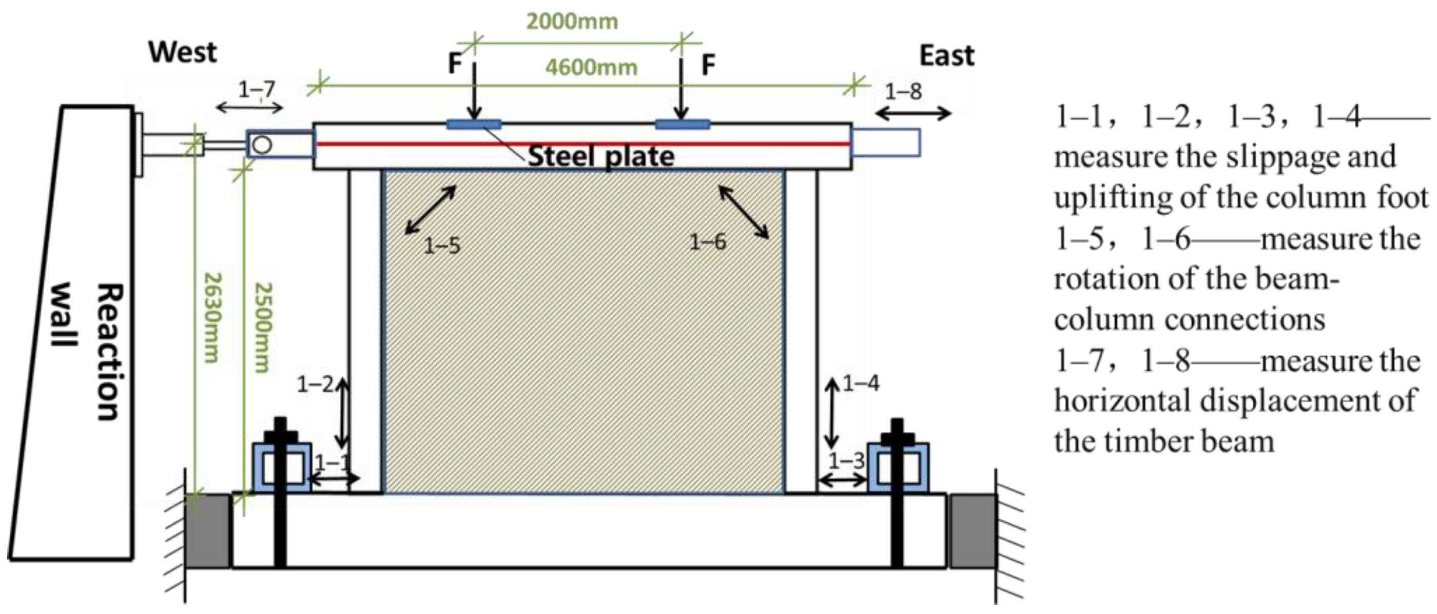
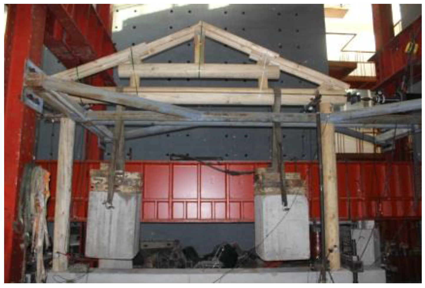
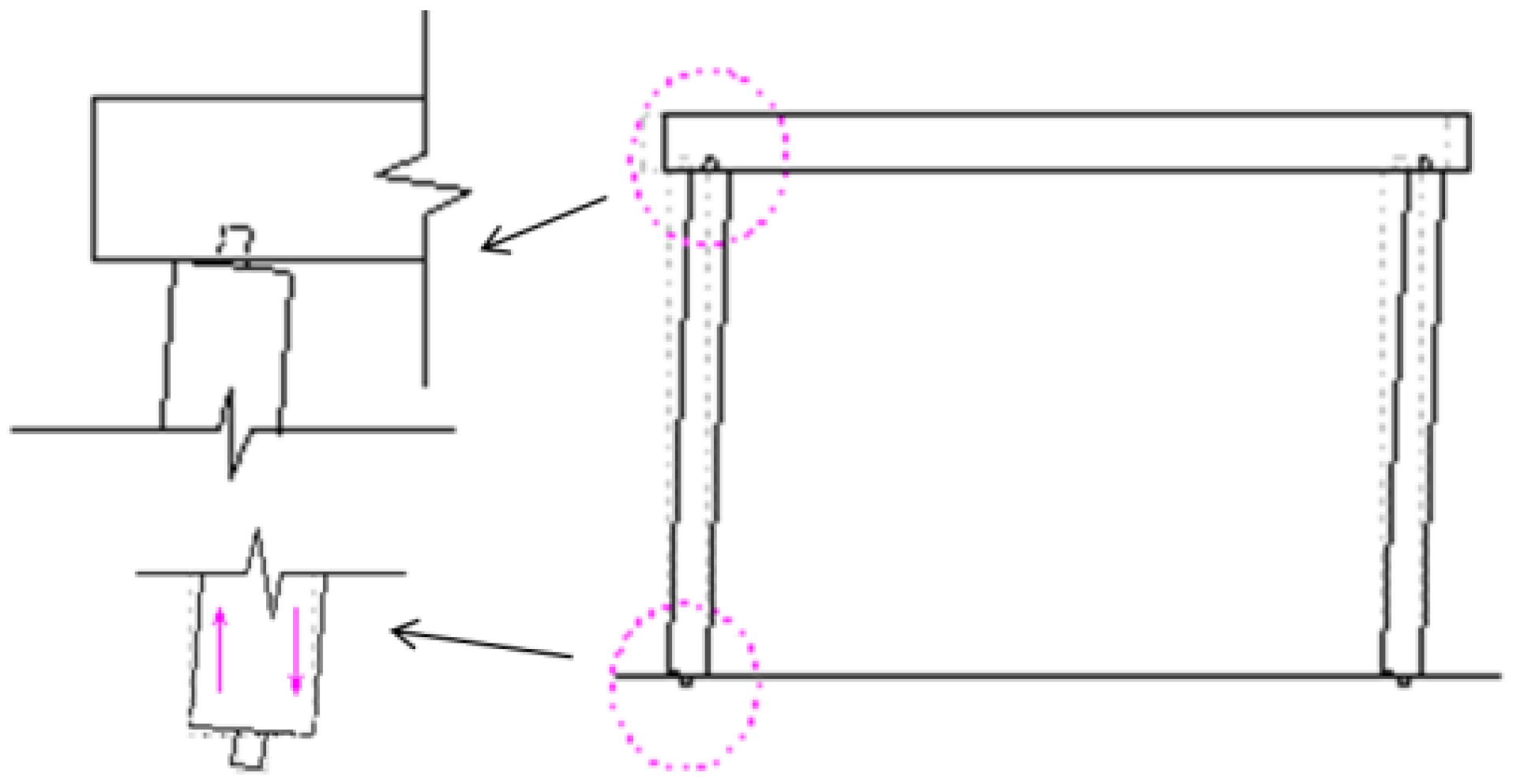
3.1. Test Configurations and Experimental Setup

In order to understand the seismic performance of the hybrid structure of timber frames with mud and stone infill, two full-scale hybrid wall specimens were reproduced and built for static cyclic in-plane loading tests, according to the field investigations. Two full-scale specimens with different vertical load applications representing the hybrid walls at different positions (external transverse wall and internal transverse wall) to bear the different vertical load from the roof’s weight and the snow load were created. Two vertical loads of 20 kN and 38 kN calculated according to roof construction practice were applied to investigate the real lateral performance of the hybrid walls and to assess the influence of this variable on the lateral response. For the same typology of traditional village dwellings, however, there were still small variations in the details for constructions. Thus, it was decided to design a representative building. The main timber skeleton consists of vertical elements (columns) and a horizontal element (a five-purlin beam). The Mantou mortise-tenon joints were used to connect the columns and the beam. The five-purlin beam had a diameter of 260 mm, and the columns had a diameter of 220 mm. The wood frame specimen had a height of 2.5 m (from the foundation to the bottom of the beam), and the columns were spaced 4 m apart, as shown in Figure 10. The Mantou tenon processed similar to a big end up square prism had an end cross-section of 50 mm × 50 mm, a top cross-section of 48 mm × 48 mm, and a height of 60 mm. The protruding pin was a cuboid shape with a cross-section of 50 mm × 50 mm and a height of 60 mm. The mortises had corresponding dimensions (large on the outside and small on the inside) to ensure a tight fit. In the traditional building, the columns were sitting on the cornerstone, and pins protruding from the bottom of the columns were inserted into an eyelet in the stone with a gap to allow for the movement of the columns. Two long concrete foundation beams used to simulate the cornerstones and the foundation were prefabricated. They had a length of 5 m, a height of 0.5 m, and a width of 0.42 m. Two slots with dimensions of 80 mm × 80 mm and a height of 60 mm were cut in the foundation beams at a distance of 4 m to simulate the eyelets.
The full-size timber frames were erected and attached to the concrete foundation. A double layer of stones and clay mud was used as an infill. The wall construction was performed by experienced local folk craftsmen in the laboratory, following traditional methods, according to the field investigation (Figure 11). The thickness of the mud and stone infill was roughly 400 mm. Stones with various dimensions ranging from 20 mm to 30 mm were used for the infill. The clay mud was mixed with 10–15 mm long straw to connect the stones. Most of the construction material used in the test was obtained from the local village area (clay and stone).
Tests were performed using a static cyclic protocol with one horizontal hydraulic jack with a maximum capacity of 100 kN of the force transducer and two vertical hydraulic jacks with a maximum capacity of 1000 kN. The movement range of the horizontal jack was ±250 mm, and that of the vertical hydraulic jack was ±150 mm. Two different pre-compression load levels were applied at the top of the five-purlin beam, (20 kN and 38 kN). The planes were produced at one-third span at the upper surface of the five-purlin beam. Small steel plates were attached to the plane surface of the five-purlin beam to distribute the vertical load applied by the vertical hydraulic jack and simulate the roof’s weight. A horizontal actuator was attached to the horizontal hydraulic jack on the reaction wall and connected to the ends of the five-purlin beam through pull rods and a pin roll. The test setup is illustrated in Figure 12. The vertical hydraulic jack provided translational motion with horizontal movement of the top timber beam through rollers on the rigid beam slide rail. The concrete foundation beam was attached to the floor with steel box beams and large steel anchor bolts. Both end surfaces of the foundation beam were supported by a hydraulic jack to avoid slipping. The vertical loads were controlled manually to ensure constant pressure. A horizontal lateral force was applied manually. The lateral resistance capacity of the walls was appropriate for the force transducer of the testing system, ensuring reliable experimental data.
The measurement system consisted of wire displacement transducers at the beam end to measure the lateral drift of the wall at the top, wire displacement transducers at the corner of the wall to measure the rotation angle of the beam-column connections, and dial gauges at the end of the columns to record the slippage and uplifting of the column ends, as illustrated in Figure 13.
Figure 13. The measurement system.The clay materials were subjected to a liquid plastic limit test. The plasticity index was 18.7, and the average compressive strength of a cube of mixed clay and straw (70.7 mm × 70.7 mm × 70.7 mm) was 1.73 MPa (Figure 14). The timber frame wood was Pinus sylvestris, grown in northern China. The material parameters of the wood property were analyzed, a bending strength test as an example is illustrated in Figure 15. The average elastic modulus of the wood was 9420 MPa parallel to the grain (EL), 1039 MPa in the radial direction (ER), and 520 MPa in the chord direction (ET). The compression strength was 28.6 MPa parallel to the grain (EL), 6.1 MPa in the radial direction (ER) and chord direction (ET), and the bending strength was 64.4 MPa.
Buildings 11 00580 g013
Figure 14. Clay material tests. (a) Liquid plastic limit test. (b) Compressive strength test.
Buildings 11 00580 g014
Figure 15. Bending strength test of Pinus sylvestris.
Buildings 11 00580 g015

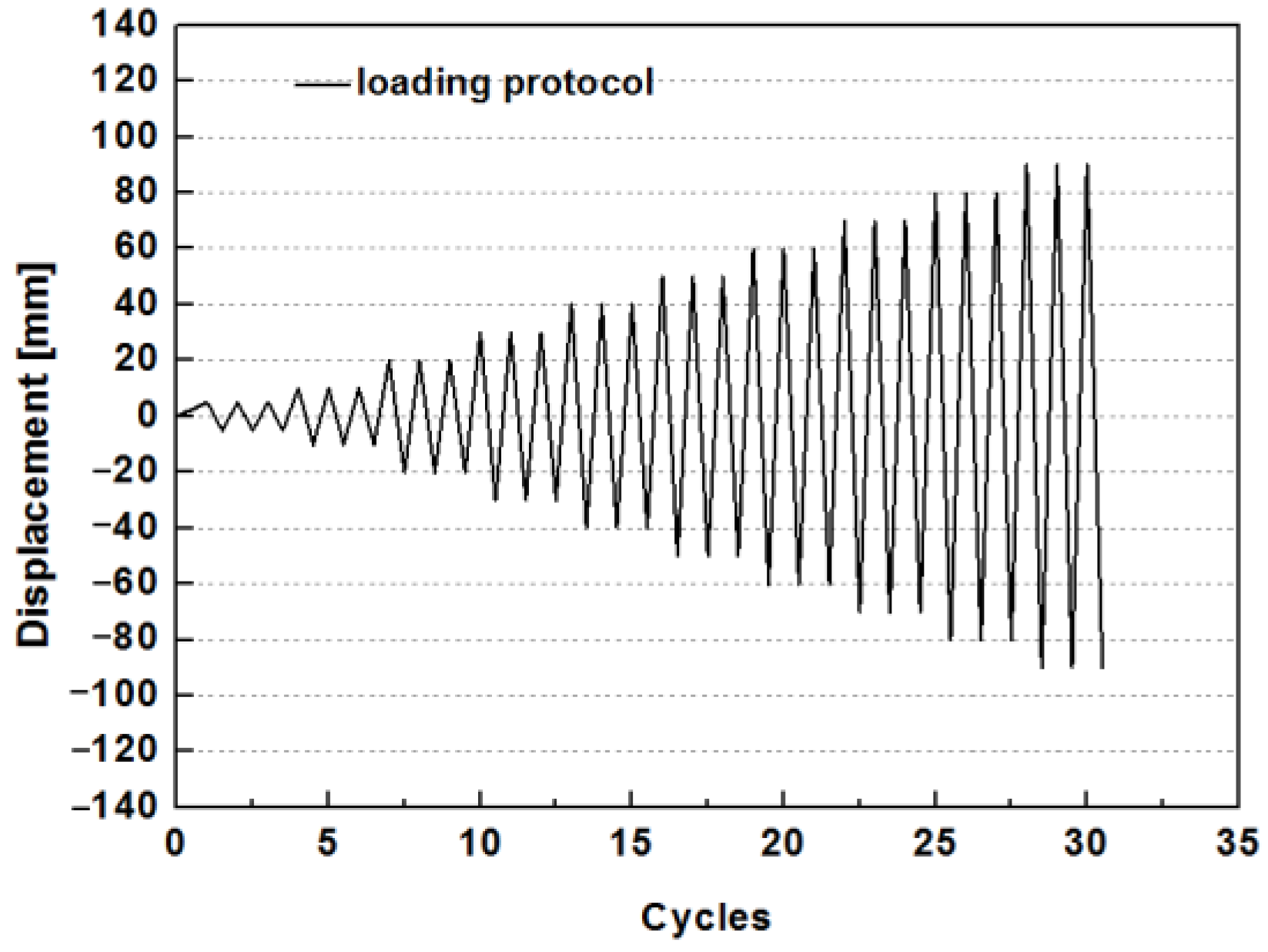
3.2. Loading Protocol

Displacement control was adopted in the static cyclic loading test according to the Specification for the seismic testing of buildings [39]; the details are shown in Figure 16. In the beginning, the preloading with two fully reversed cycles at 2 mm displacement was carried out to check the loading system prior to the formal test. Then, the formal test started with the horizontal displacement increased by 5 mm with three fully reversed cycles before the drift ratio of 0.2%. Subsequently, the horizontal displacement increased by 10mm after the drift ratio of 0.2% in each phase with three fully reversed cycles of equal amplitude at displacements of 10 mm, 20 mm, 30 mm, and larger values with an increment of 10 mm. The loading process stopped when the lateral resistance of the hybrid walls dropped below 80% of the maximum lateral capacity.

4. Experimental Results

The results and discussion of the cyclic test are divided into four parts: (1) the description of the experimental phenomena and typical failure modes of the hybrid walls; (2) a discussion of the force-displacement hysteresis curves of the hybrid walls; (3) an assessment of the seismic performance of the hybrid walls; (4) a discussion of the contribution of the infill to the seismic performance based on a comparison with previous test results of timber frames with no infill.

4.1. Experimental Phenomena

Specimen S1, representing the external wall of the dwelling, was subjected to a vertical load of 20 kN. Specimen S2, representing the internal wall, was loaded vertically with a force of 38 kN. The tests revealed good compatibility between the timber frame and the mud-stone infill, with a horizontal displacement of 10 mm (0.38% drift). In the initial phase, the confinement of the frame kept the mud and stone infill in place, and the infill strengthened the lateral stiffness of the frame. With an increase in horizontal displacement loading, the level of cooperation between the timber frame and the infill decreased due to the larger lateral drift of the timber frame and the smaller drift of the stone wall. The interface between the infill and timber frame was very weak, resulting in the early detachment of the infill wall from the timber frame. The detachment resulted in larger gaps at the upper end of the column and smaller gaps between the wood frame and the infill wall at the bottom of the columns, as illustrated in Figure 17. The timber columns compressed one side of the stone wall and separated from the other side, resulting in mortar and stone dislocation, wall bulging, and falling stones. The details of the results for the two full-size specimens are as follows:
For specimen S1, the mud and stone infill wall separated from the timber frame and bulged at the corner after the loading displacement of 70 mm (Figure 18). At 80 mm horizontal loading displacement, several stone blocks failed at the corner of the infill wall, and the sound of energy dissipation of the mortise and tenon joints due to friction “Pa Pa” was heard (Figure 19). Meanwhile, the wire displacement transducers near the corner of the infill wall and the dial gauges at the end of the columns were damaged by falling stones. Significant damage to the wall occurred after 100 mm horizontal displacement loading (3.8% drift), such as stones falling from the single layer of the wall, representing 1/6 of the wall area (Figure 20). More significant damage to the stone infill wall was observed after 120 mm horizontal displacement loading (4.56% drift), such as a cavity due to falling stones (1/6 of the wall area) (Figure 21). After the last displacement loading of 130 mm (4.94% drift), the stones failed in about 1/3 of the wall area, and the lateral capacity of the hybrid wall dropped to 30% of the maximum capacity (Figure 22). However, the timber frame rocked with a slight uplift and slowly fell to the ground during cyclic loading. The timber frame did not show any significant damage during and after cyclic loading.
For Specimen S2, the surface of the stone wall remained flat except for some bulging and cracks at the corner after 80 mm displacement loading (3.04% drift) (Figure 23). Similar to the S1 specimen, stones fell from the single layer of the wall in about 1/6 of the wall area after 90 mm horizontal displacement loading (Figure 24). The same location on the other layer of the wall became loose and cracked (Figure 25); however, the wall did not fail until 140 mm loading displacement (5.32% drift), and a cavity occurred, representing about 1/6 of the wall area (Figure 26). In the last displacement loading cycle of 150 mm (5.74% drift), the lateral capacity dropped to roughly 6 kN with more stones failing, and the test was stopped. However, the timber frame remained undamaged during the loading process.
Since the hybrid structure specimen was subjected to in-plane loading, the confining effect of the wood frame on the infill and the interface between the frame and the infill were weak. Thus, the cooperation between the wood frame and the infill was inadequate. Early separation occurred between the infill wall and the frame. After large deformation occurred, the compression effect of the wood column on the infill resulted in damage, such as cracks, sliding, loosening, and falling of the infill. Similar to reinforced concrete frames with the infill wall, the mud and stone infill behave strong diagonal bracing effect [40] and the damage near the top of the columns and beam-column connections occurred first. Differently, the compression damage from the timber frame resulted in the detachment of the double-layer mud and stone wall, similar to the shear of the middle layer of the infill wall in the thickness direction. The whole deformation mode of the hybrid specimen was shear deformation. However, the hybrid wood-stone structure behaved favorably because the wall collapsed, but the structure remained standing. In other words, the timber frame was undamaged due to the energy dissipation through the sliding and falling of the mud and stone, which is a significant contribution to the seismic behavior.
In addition, the strength and viscosity of the mud have a significant effect, i.e., the use of sandy soil will result in more cracking, sliding, and potential collapse of the infill wall than the use of clay soil. The selection of irregular stones has a important effect, i.e., more involvement of pebbles will lead into more sliding and collapse of the infill wall than the use of irregular rubble.

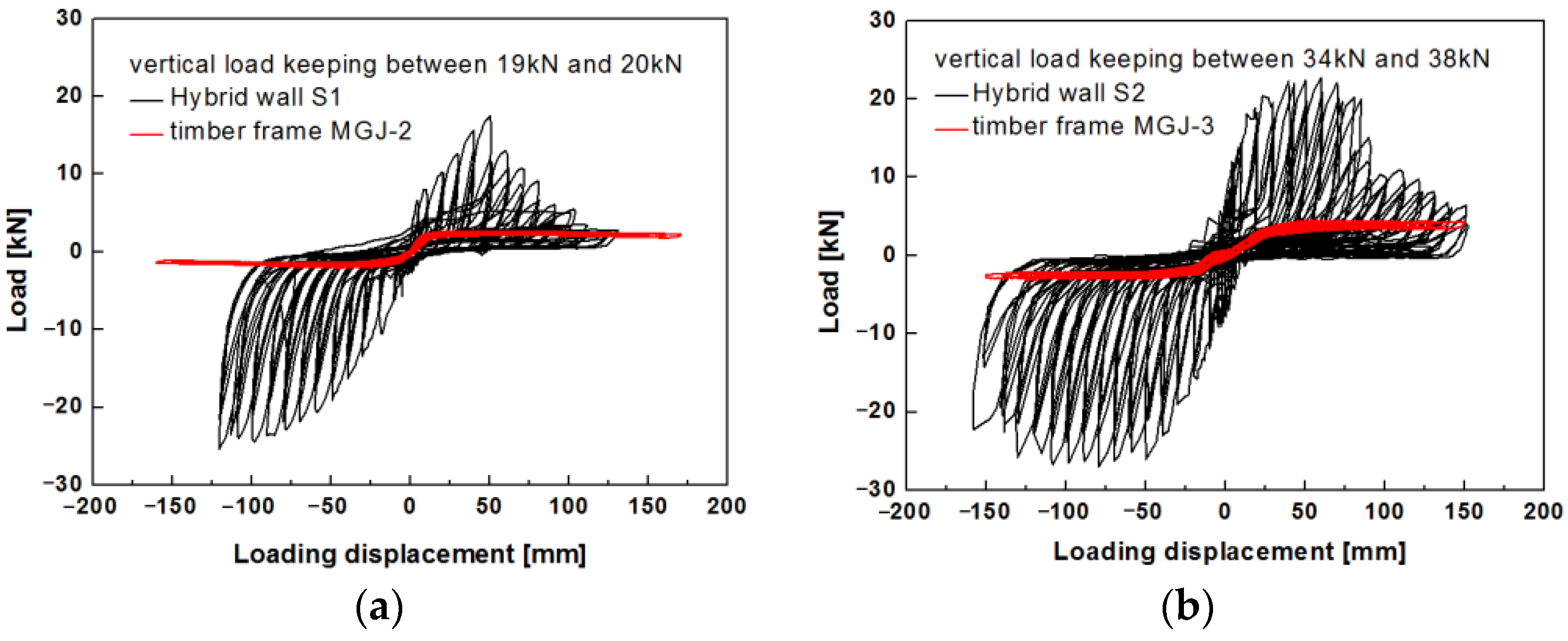
4.2. Typical Hysteresis Curves

The monitored lateral load and recorded horizontal loading displacement at the beam were obtained to plot the hysteresis curves. The two specimens subjected to different vertical precompression levels during cyclic loading exhibited similar behavior. The load-horizontal displacement hysteresis loops exhibit strong pinching with plump ends and slender waists, indicating slipping of the hybrid component. The load-displacement hysteresis curves of S1 and S2 are plotted in Figure 27. The gradient of the unloading curve was close to zero, and the load dropped rapidly, indicating a gap and deformation incompatibility between the wood frame and the infill. In addition, the hysteresis loops of both specimens are asymmetric. During loading, a local collapse occurred at one corner of the infill wall; however, the stones and mud at the other locations were not loosened or did not slip. As a result, the lateral resistance during reverse cyclic loading remained constant for a long time.
Specimen S1 reached a strength of 17.58 kN at the positive loading displacement of 50 mm (1.9% drift), and subsequently, a significant decline in the lateral resistance capacity was observed. Meanwhile, at a negative maximum lateral resistance (25.34 kN), specimen S1 did not fail until about 125 mm (4.7% drift) for negative loading displacement. Specimen S2 had a strength of 22.74 kN at positive loading of 60 mm (2.3% drift) and a strength of 26.99 kN at negative loading of 80 mm (3% drift). The hysteresis curves of the specimens indicate that S2 with the higher vertical precompression load showed higher lateral resistance capacity than S1, which had larger hysteresis loops. The uplift of the column foot recorded by the undamaged dial gauges on one side is plotted in Figure 28. The maximum uplift (13 mm) indicated the slight rocking of the timber frame; however, the increase in the vertical precompression had a minimal effect on the rocking behavior of the timber frame in the hybrid structure.

4.3. Seismic Performance

The strength, stiffness, energy dissipation, damping ratio, and ductility were assessed to determine the specimens’ seismic performance.

4.3.1. Idealized Bilinear Curves

The skeleton curves of the two specimens subjected to different vertical precompression loads are shown in Figure 29. The equivalent bilinear diagrams based on the hysteresis envelope were obtained using the ASTM 2126-09 standard [41]. The yield point was defined according to the bilinear curves using the equivalent energy elastic-plastic (EEEP) method.
Table 1 summarizes the characteristic seismic parameters of S1 and S2 for four key states. The initial stiffness (Ke) is defined as the secant stiffness between 0% and 40% of the peak load; Fp is the force at the strength limit state; Dp is the corresponding displacement at that strength; Fu is defined as failure limit state at 80% of the strength after the peak; Du is defined as the failure deformation at 80% of peak load; Fy is related to the load at the yield limit; Dy denotes the displacement at the yield limit; µ = Du/Dy is the ductility ratio. Specimen S2 with a higher vertical load on the internal wall had a larger initial stiffness with an average of 2.13 kN/mm than S1 (average of 0.96 kN/mm). The initial lateral stiffness of the internal wall was higher for S2 than for S1. The average lateral resistance of the hybrid wood-stone wall was about 20 kN. However, as the vertical load increased from 20 kN to 38 kN, the lateral resistance increased from 21.46 kN (S1) to 24.87 kN (S2), an increase of 16%. The hybrid wood-stone walls had ductility ratios above 10, and S2 had a higher value than S1 (12.28 versus 10.45). Therefore, a larger vertical load applied to the beam resulted in higher lateral resistance of the hybrid wall, causing a stiffening of the hybrid wall and increased load capacity. The internal wall (S2) had higher lateral resistance than the external wall (S1).

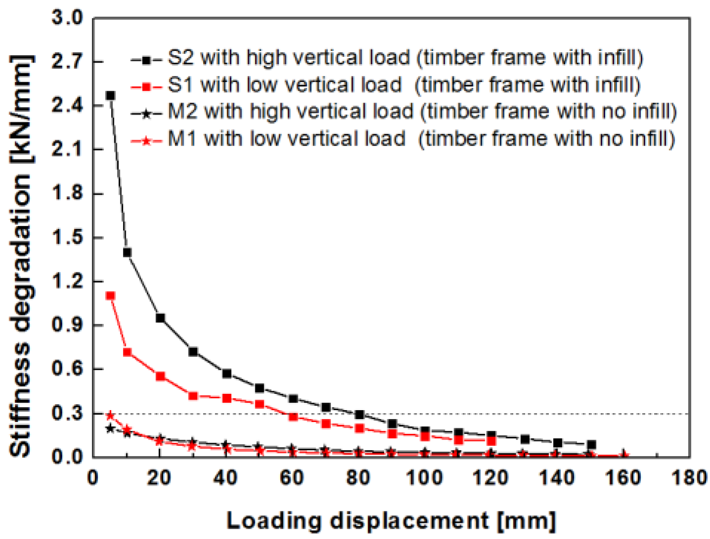
4.3.2. Stiffness Degradation Behavior

According to the specification for seismic tests of buildings [39], the secant stiffness instead of the tangent stiffness was used to assess the stiffness degradation of the component or structure.
K j = | + F j | + | F j | | + Δ j | + | Δ j |
where +Fj and −Fj are the generalized positive and reverse loads at the jth loading level (in kN), respectively; +Δj and −Δj are, respectively, the positive and reverse displacements at the jth loading level (in mm). The stiffness degradation curves of the two specimens are illustrated in Figure 30. The effects of the vertical load on the lateral resistance of the hybrid wall are evident. The stiffness curves show a degradation trend with a significant decrease at the beginning (0–20 mm displacement), followed by a gradual decrease (20 mm–80 mm displacement) and stabilization (greater than 80 mm displacement). It is observed that the stiffness of S2 is larger than that of S1 when the drift is less than 3.04% (80 mm displacement). When the drift is less than 20 mm (0.76% drift), the secant stiffness of S2 is twice that of S1. In the horizontal displacement range of 20 mm to 30 mm, the secant stiffness of S2 is 1.5 times that of S1. For a displacement greater than 80 mm, the stiffness degradation curves of the two specimens are similar, with values less than 0.2 kN/mm. The results indicate that an increase in the vertical load results in an increase in the stiffness of the hybrid wall.

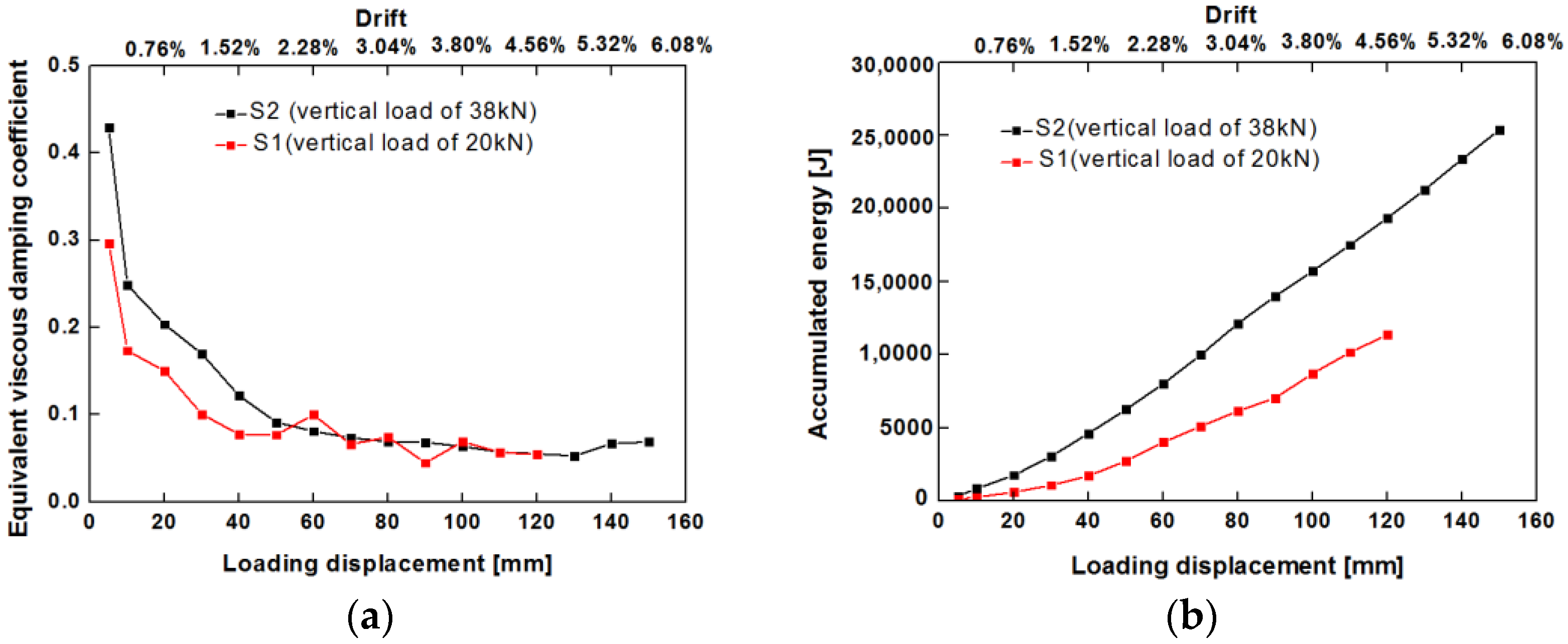
4.3.3. Energy Dissipation

The energy dissipation capacity of a structure is typically accessed by the equivalent viscous damping coefficient and accumulated energy. The equivalent damping coefficient of the system is defined as [42]:
h e = 1 2 π E d E e + + E e
where Ed is the total dissipated energy of the specimen in the first cycle at different displacement levels; Ee++Ee are the potential energies at maximum deformation in the first cycle in the positive and negative directions at the displacement control level. The equivalent viscous damping coefficients of the two specimens show a decreasing trend with a large rate of change before 50 mm loading displacement (2% drift, corresponding to the strength limit point of S1) with a range of 0.8 to 0.2, followed by a slow rate of decrease and stabilization at about 0.08, as illustrated in Figure 31a. The viscous damping ratio is higher for S2 than S1 before 50 mm loading displacement (0.09–0.43 for S2 and 0.08–0.3 for S1). An increase in the equivalent viscous damping coefficient occurs as the vertical precompression increases. These results indicate that the internal walls of traditional village dwellings have higher energy dissipation capacity than the external transverse walls.
The accumulated energy was calculated using the cumulative accumulation of the integral area of hysteresis loops. The cumulative dissipated energy of the two specimens increases with an increase in lateral drift and is higher for S2 with the larger vertical precompression level, as shown in Figure 31b. The lateral drift of S2 is less than that of S1 for dissipating the same amount of energy. Increasing the vertical load on the beam enhances the seismic dissipation capacity. Furthermore, the seismic capacity is higher for the internal wall than the external wall.

4.4. Comparison with Experimental Results of Timber Frames with No Infill

We compared the results with those of a timber frame with the same dimensions and no infill to assess the seismic performance of traditional Chinese houses with mud and stone infill. A full-scale post-and-lintel timber frame of a traditional residence was fabricated and subjected to pseudo-static cyclic lateral loading (Figure 32). The experimental results of this type of timber frame were reported in [7]. The timber frame M1 (M2) in this study subjected to a vertical load of 19 kN (34 kN) corresponds to specimen MGJ-2 (MGJ-3) in [7], representing an external transverse wall (internal transverse wall) in a traditional village residence. The vertical loads applied to the timber frame without infill were slightly lower than those applied to the hybrid wood-stone wall. The reason is that some of the weight of the mud and stone infill in the triangular area of the five-purlin flush-gable roof is transferred to the wooden frame, and some are transferred to the thick stone wall below.
The timber frames without infill exhibited different hysteretic behavior than those with mud and stone infill. The bare wood frame is a rocking system characterized by uplifting and lowering of the column foot. When the timber frame is displaced to the right (left), the left (right) side of the column foot is lifted up from the foundation, and the right (left) side of the column foot is compressed, as shown in Figure 33. The greater the displacement drift of the timber frame, the greater the uplifting of the column foot is, and the smaller the compression area of the column foot is. The hysteresis loops of the bare wood frame are slender and Z-shaped, indicating the continuous slipping and friction between the mortises and tenons. In contrast, the hysteresis loops of the hybrid wood-stone walls are 8-shaped with plump ends and pinching in the middle, as illustrated in Figure 34.
Table 2 lists the values of the crucial seismic parameters (initial stiffness and strength) of the timber frames with and without infill. The initial lateral stiffness of the bare wood frames was less than 0.5 kN/mm. The infill substantially increased the lateral stiffness, with average values of 0.96 kN/mm for S1 and 2.13 kN/mm for S2. Moreover, the lateral resistance capacities of the bare wood frames were very low (2 kN to 4 kN), whereas those of the timber frames with the infill ranged from 20 kN to 25 kN. The infill substantially increased the lateral capacity by about 20 kN. The hybrid wood-stone walls can provide great lateral resistance capacities about 8–10 times than that of bare wood frames.
The comparison of the stiffness degradation between the timber frames and hybrid wood-stone walls is provided in Figure 35. The timber frame without infill has substantially lower stiffness values (less than 0.3 kN/mm) than the timber frame with infill, whose maximum value is 2.5 kN/mm before 50 mm loading displacement (2% drift). Afterward, the stiffness degradation of timber frame with infill is close to that of the bare timber frame. The results indicate that the lateral resistance stiffness of the timber frame with infill decreased rapidly after 50 mm of loading displacement.
The comparison of the equivalent viscous damping coefficient between the timber frames and hybrid wood-stone walls is presented in Figure 36. The equivalent viscous damping coefficients are higher for low drift values and subsequently decrease before stabilizing. It is observed that the equivalent viscous damping coefficient is affected by the infill and the vertical load. At a high vertical load, the viscous damping coefficient is higher for the timber frame with infill than without infill at low drift values (50 mm displacement, 2%), and the ranges are 0.8–0.42 for the former and 0.8–0.3 for the latter. The values then decrease and stabilize between 0.06 and 0.08. Similar trends are observed for both types of timber frames at low vertical loads. These results differ from those of a study of traditional Portuguese buildings. The coefficients were 0.17–0.20 for timber frames with infill and 0.19–0.20 for timber frames without infill at low drift values [43]. However, a high vertical load increases the viscous damping of timber frames with infill and without infill.

5. Conclusions

An experimental study was conducted for the first time on a traditional Chinese building with a wood frame with mud and stone infill. The full-scale specimens were constructed based on representative residences and better reflected the seismic performance of the hybrid wall than small-size specimens. Thus, the experiment provides meaningful results on the seismic behavior of traditional residential houses. This study also provides a scientific reference for the seismic assessment, repair, and protection of traditional Chinese village buildings.
A field investigation was conducted in rural areas in northern China. In this area, most of the traditional houses have a timber frame with four beams and eight columns with mud and stone infill. Full-scale specimens based on the prototype were fabricated and subjected to pseudo-static cyclic lateral loading tests. The following conclusions were drawn:
(1)
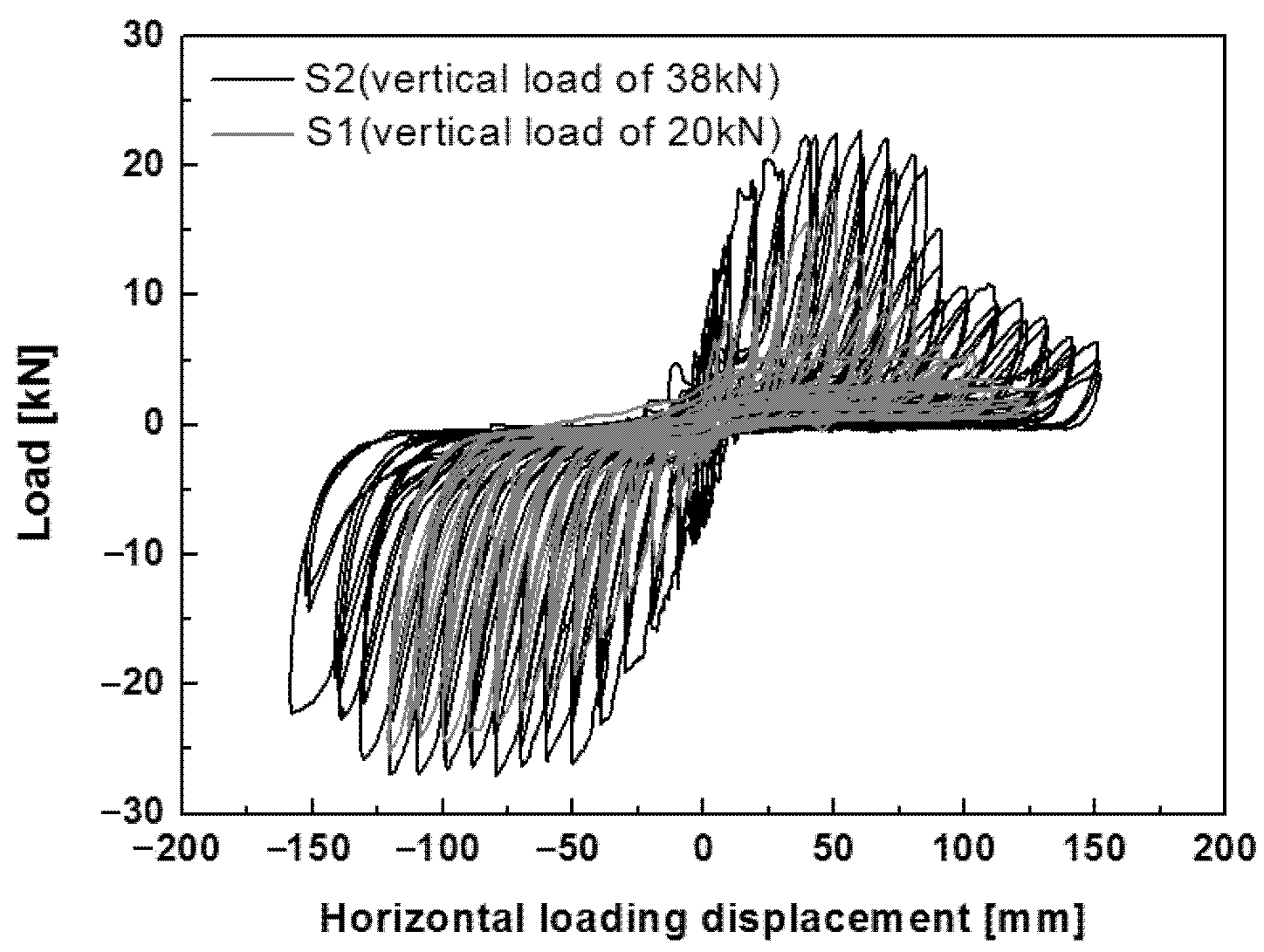
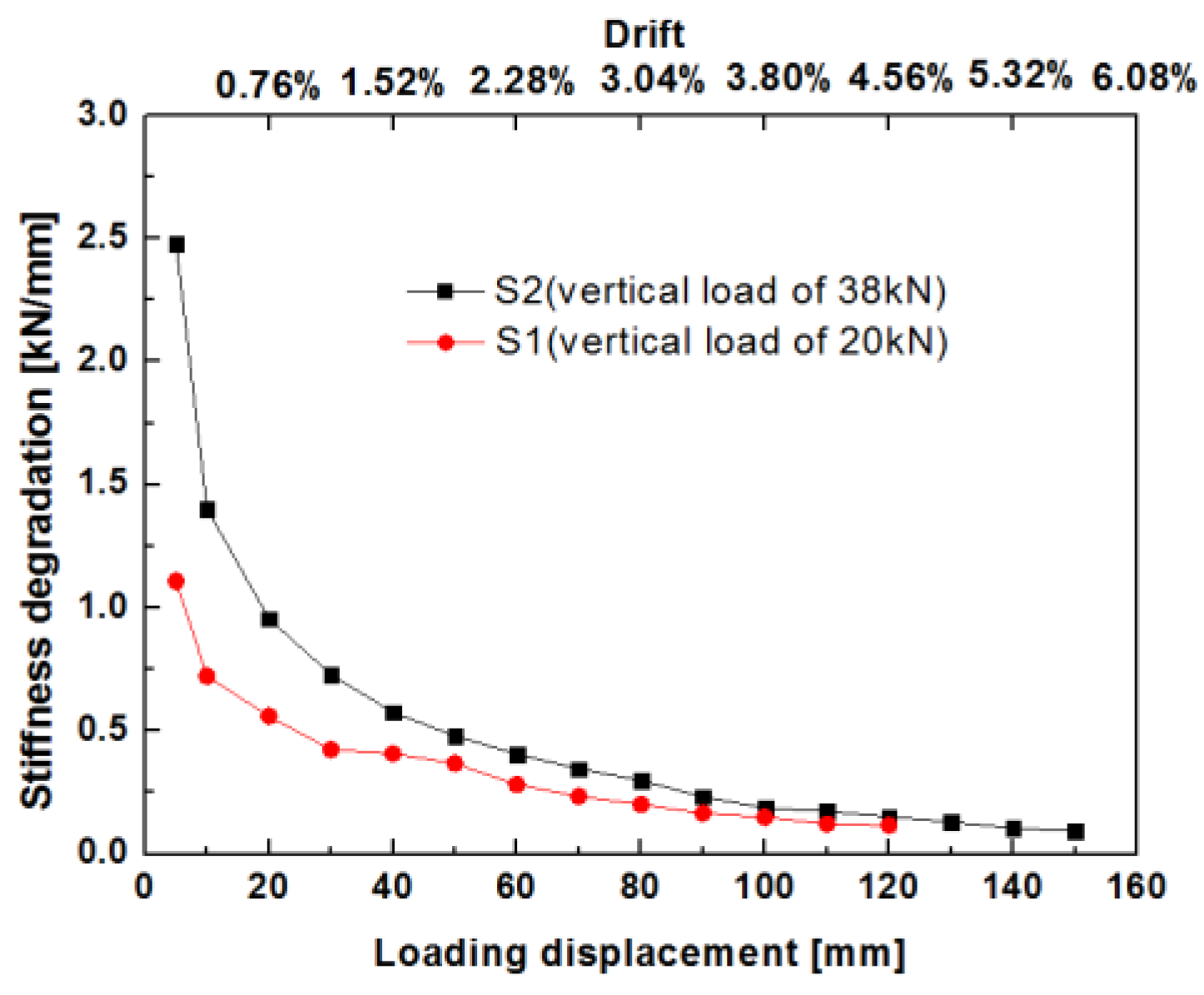
The mud and stone infill considerably changed the lateral resistance responses of the walls. The timber frame with Mantou mortise and tenon joints acted as a rocking system, exhibiting weak lateral stiffness of less than 0.5 kN/mm and low strength of less than 5 kN with low energy dissipation. The cooperation between the timber frame and stone infill resulted in high lateral strength of over 20 kN, and the lateral stiffness was three times higher than that of the timber frame without infill. The timber frame with mud and stone infill also showed a high ductility factor (>10). The infill had a critical influence on the lateral performance of traditional village residence buildings, acting as the dominant resisting mechanism.
(2)
An increase in the vertical load resulted in an increase in the lateral resistance of the timber frame with infill walls. A larger applied vertical load resulted in higher lateral stiffness, higher lateral strength and greater energy dissipation capacity. Since different vertical loads were transferred at different positions, the lateral resistance at the internal transverse wall (24.87 kN) was larger than that at the external gable wall (21.46 kN), representing an increase of 16%. The lateral stiffness of the internal transverse wall (2.13 kN/mm) was greater than that of the external gable wall (0.96 kN/mm), representing a one-fold increase. The energy dissipation of the internal transverse wall was greater than that of the external gable wall.
(3)
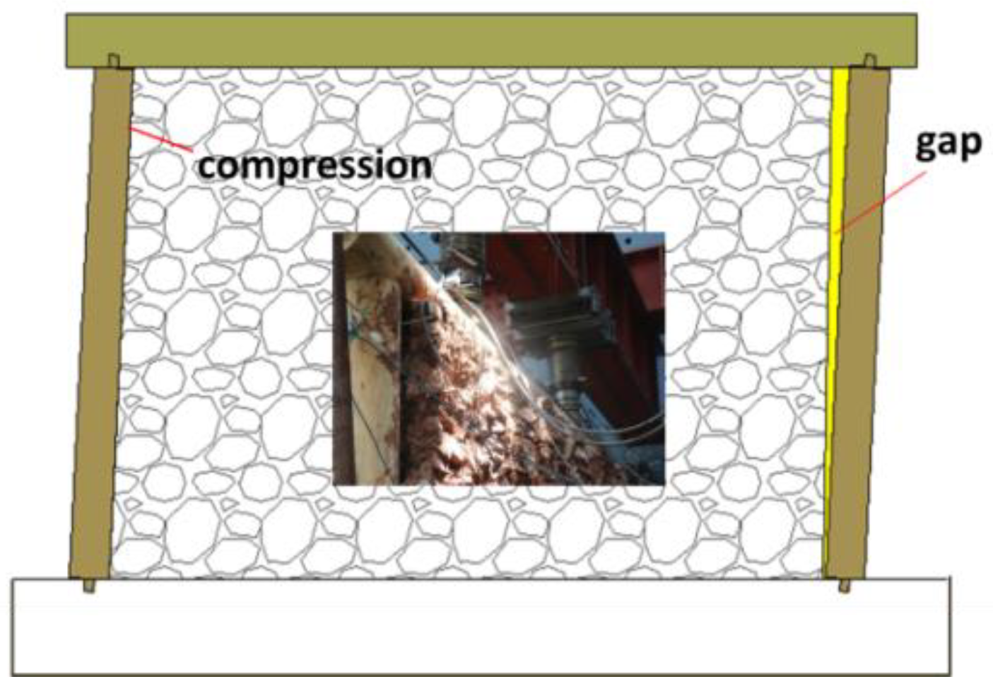
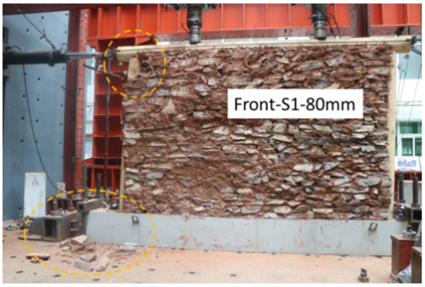
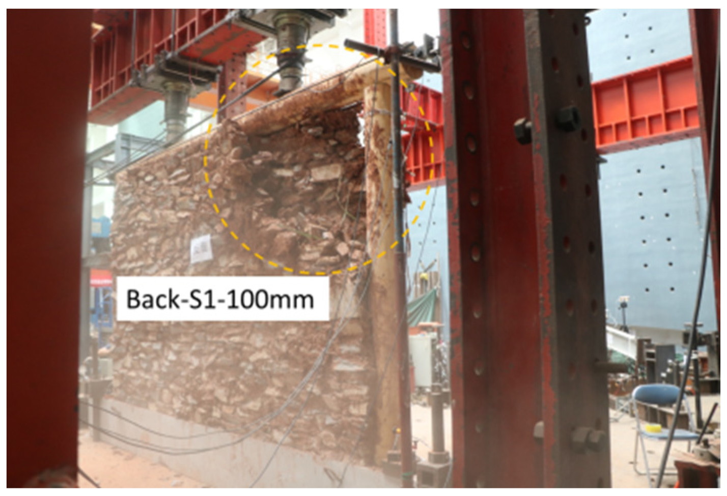
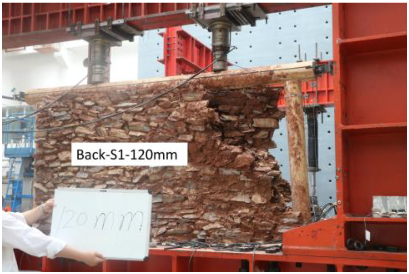
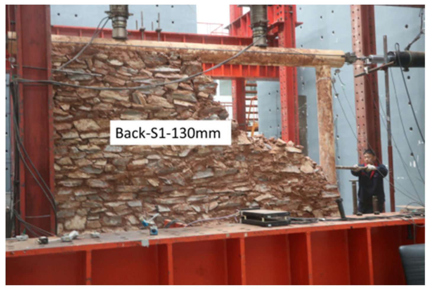
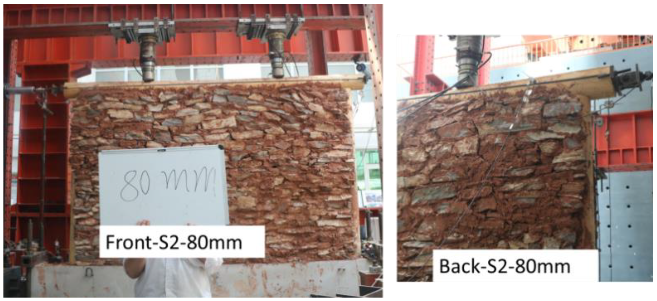
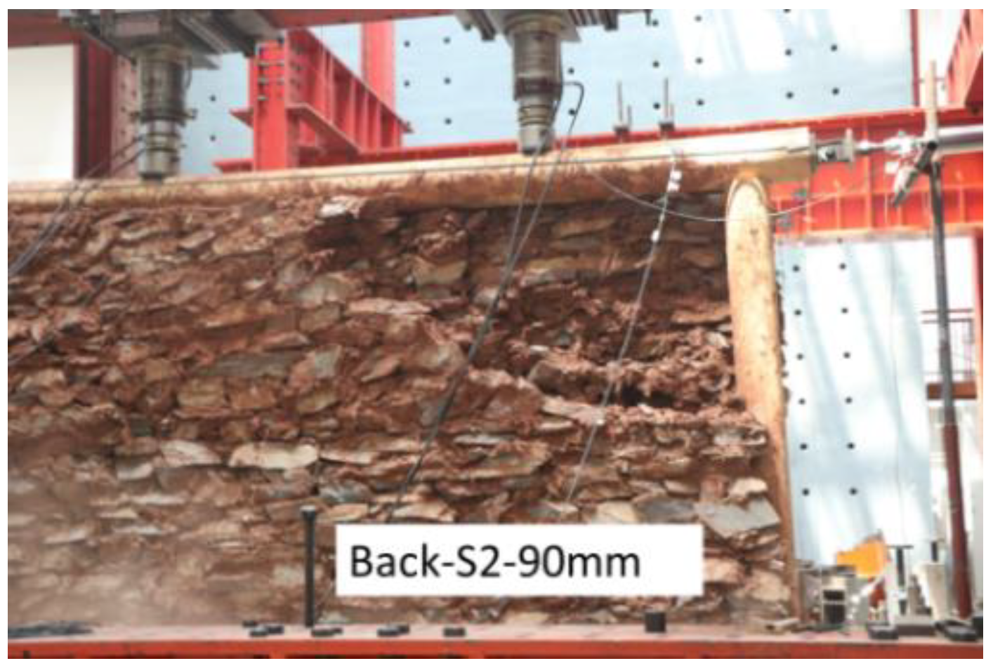
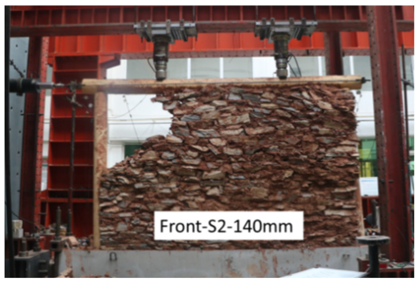
The main in-plane failure mode of the timber frame with mud and stone infill included stones falling and infill collapse, but there was no damage to the timber frame. This response indicates that the wall might collapse during a seismic event, but the house would remain standing. The failure reason was that the wood column exerted pressure on the infill, resulting in shear damage of the infill wall in the thickness direction, due to the incompatibility of the deformation between the timber frame and stone infill.
(4)
These hybrid walls are different from Chuan-Dou timber frame with infilled timber panel with plentiful Fang similar to the tie beam. The infilled timber panel with plentiful Fang ensures the stability of Chuan-Dou timber structure, which is resilient enough in the earthquake. These hybrid walls are also different from timber frames consisting of diagonal bracing, tie beam and half-cross connections with mud and stone infill used in rural areas in Europe. The diagonal bracing, tie beam and half-cross connections provide better compatibility of the deformation between the wood frame and the infill.
(5)
More research is required to improve the deformation compatibility and strengthen the links between the timber frame and stone infill and prevent the out-of-plane collapse of the stone wall for traditional wood residences in northern China. We will focus on these topics in a future study.

Author Contributions

Data curation, X.Y.; Formal analysis, X.Y.; Funding acquisition, Y.S. and W.H.; Investigation, P.Y. and G.W.; Methodology, Y.S. and G.W.; Project administration, H.L.; Resources, P.Y.; Supervision, H.L.; Writing—original draft, Y.S.; Writing—review & editing, Y.S. and W.H. All authors have read and agreed to the published version of the manuscript.

Funding

This work was supported by National Natural Science Foundation of China (52008011) and Science and Technology Project of Beijing Municipal Education Commission (KM201910005019) and China Postdoctoral Science Foundation (2019M660501) and Beijing Municipal Natural Science Foundation (8204058).

Institutional Review Board Statement

Not applicable.

Informed Consent Statement

Not applicable.

Data Availability Statement

The data in this paper are given in the tables and figures within the manuscript.

Conflicts of Interest

The authors declare no conflict of interest.

References

  1. Xie, Q.; Zhang, L.P.; Wang, L.; Zhou, W.; Zhou, T. Lateral performance of traditional Chinese timber frames: Experiments and analytical model. Eng. Struct. 2019, 186, 446–455. [Google Scholar] [CrossRef]
  2. Maeno, M.; Suzuki, Y.; Ohshita, T.; Kitahara, A. Seismic response characteristics of traditional wooden frame by full-scale dynamic and static tests. In Proceedings of the 13th World Conference on Timber Engineering (WCTE), Vancouver, BC, Canada, 1–6 August 2004; p. 1184. [Google Scholar]
  3. Chun, Q.; Yue, Z.; Pan, J.W. Experimental study on seismic characteristics of typical mortise-tenon joints of Chinese southern traditional timber frame buildings. Sci. China Technol. 2011, 54, 2404–2411. [Google Scholar] [CrossRef]
  4. Li, X.; Zhao, J.; Ma, G.; Chen, W. Experimental study on the seismic performance of a double-span traditional timber frame. Eng. Struct. 2015, 98, 141–150. [Google Scholar] [CrossRef]
  5. Li, X.; Zhao, J.; Ma, G.; Huang, S. Experimental study on the traditional timber mortise-tenon joints. Adv. Struct. Eng. 2015, 18, 2089–2102. [Google Scholar] [CrossRef]
  6. Li, S.; Zhou, Z.; Luo, H.; Milani, G.; Abruzzese, D. Behavior of traditional Chinese mortise-tenon joints: Experimental and numerical insight for coupled vertical and reversed cyclic horizontal loads. J. Build. Eng. 2020, 30, 101257. [Google Scholar] [CrossRef]
  7. Shen, Y.; Liu, H.; Zhou, J.; Chen, Z.; Wang, L.; Zhou, H. Experimental study on lateral performance of post-and-lintel timber frame in traditional residences. J.B. Univ. Technol. 2021, 47, 759–772. [Google Scholar] [CrossRef]
  8. Yao, K.; Zhao, H.T.; Ge, H.P. Experimental studies on the characteristic of mortise-tenon joint in historic timber buildings. Eng. Mech. 2006, 23, 168–173. (In Chinese) [Google Scholar] [CrossRef]
  9. Sui, Y.; Zhao, H.; Xue, J.; Zhang, H.; Xie, Q. Experimental study on characteristics of mortise-tenon joints in historic timber buildings. World Earthq. Eng. 2010, 26, 88–92. (In Chinese) [Google Scholar] [CrossRef]
  10. Gao, D.; Deng, H.; Liu, J.; Li, F.; Yang, Y. Pseudo-static experimental study on mortise and tenon joints of timber structures of Chinese Ming and Qing Dynasties. World Earthq. Eng. 2014, 30, 8–16. (In Chinese) [Google Scholar]
  11. Li, Y.Z.; Cao, S.Y.; Xue, J.Y. Analysis on mechanical behavior of dovetail mortise-tenon joints with looseness in traditional timber buildings. Struct. Eng. Mech. 2016, 60, 903–921. [Google Scholar] [CrossRef]
  12. Ma, L.; Xue, J.; Dai, W.; Zhang, X.; Zhao, X. Moment-rotation relationship of mortise-through-tenon connections in historic timber structures. Constr. Build. Mater. 2020, 232, 117285. [Google Scholar] [CrossRef]
  13. Chen, L.K.; Li, S.C.; Zhao, K.P.; Chen, Z.Y.; Song, T.; Zhang, L.; Jang, Z.J. Experimental and numerical investigation on seismic performance of one-way straight mortise-tenon joints based on a novel method to simulate damage of deteriorated ancient Chinese timber buildings. Perform. Constr. Facil. 2020, 34, 04019119. [Google Scholar] [CrossRef]
  14. Xie, Q.; Zheng, P.J.; Xiang, W.; Cui, Y.; Zhang, F. Experimental study on seismic behavior of damaged straight mortise-tenon joints of ancient timber buildings. J. Build. Struct. 2014, 35, 143–150. (In Chinese) [Google Scholar] [CrossRef]
  15. Xue, J.; Xia, H.; Li, Y.; Dai, W. Experiment study on seismic behavior of penetrated mortise-tenon joints under different degree of looseness in ancient buildings. J. Xi’an Univ. Arch. Technol. 2017, 49, 463–477. (In Chinese) [Google Scholar] [CrossRef]
  16. Xue, J.; Xu, D.; Ren, G.; Guo, R. Shake table test on seismic performance of column and tie wooden structure in traditional residence. China Civ. Eng. J. 2019, 52, 5–14. (In Chinese) [Google Scholar] [CrossRef]
  17. Wang, H.; Shang, S.; He, F.; Huang, S.; Deng, T.; Liu, D. Shaking table tests of Chinese traditional wood building and light wood framed building. J. Build. Struct. 2012, 33, 138–143. (In Chinese) [Google Scholar] [CrossRef]
  18. Xue, J.; Xu, D.; Guo, R. Shaking table tests and contrastive analysis for column-and-tie wooden buildings with and without infills. J. Vib. Shock. 2020, 39, 184–192. (In Chinese) [Google Scholar] [CrossRef]
  19. Xiong, H.; Wang, J.; Wu, L.; Chen, L. Experiment study on lateral resistance performance of Chuandou wooden frame structures. J. Build. Struct. 2018, 39, 122–129. (In Chinese) [Google Scholar] [CrossRef]
  20. Makarios, T.; Demosthenous, M. Seismic response of traditional buildings of Lefkas Island, Greece. Eng. Struct. 2006, 28, 264–278. [Google Scholar] [CrossRef]
  21. Ruggieri, N.; Zinno, R. Behavior of the Borbone constructive system under cyclic loading. In Proceedings of the 1st International Conference on Historic Earthquake-Resistant Timber Frames in the Mediterranean Area (Heart), Cosenza, Italy, 4–5 November 2013. [Google Scholar]
  22. Meireles, H.; Bento, R.; Cattari, S.; Lagomarsino, S. A hysteretic model for frontal walls in Pombalino buildings. Bull Earthq Eng. 2012, 10, 1481–1502. [Google Scholar] [CrossRef]
  23. Du, A.; Ferreira, J.G.; Guerreiro, L.; Branco, F.; Goncalves, A.M. Timbered masonry for earthquake resistance in Europe. Mater. Constr. 2012, 62, 615–628. [Google Scholar] [CrossRef]
  24. Langenbach, R. From “opus craticium” to the “Chicago frame”: Earthquake resistant traditional construction. Int. J. Archit. Herit. 2007, 1, 29–59. [Google Scholar] [CrossRef]
  25. Poletti, E.; Vasconcelos, G. Seismic behavior of traditional timber frame walls: Experimental results on unreinforced walls. B. Earthq. Eng. 2015, 13, 885–916. [Google Scholar] [CrossRef]
  26. Yasemin, D.A. Seismic resistance of traditional timber-frame hımış structures in Turkey: A brief overview. Int. Wood. Prod. J. 2017, 8, 21–28. [Google Scholar] [CrossRef] [Green Version]
  27. Gülkan, P.; Langenbach, R. The earthquake resistance of traditional timber and masonry dwellings in Turkey. In Proceedings of the 13th World Conference on Timber Engineering (WCTE), Vancouver, BC, Canada, 1–6 August 2004. [Google Scholar]
  28. Vintzileou, E.; Zagkotsis, A.; Repapis, C.; Zeris, C. Seismic behavior of the historical structural system of the island of Lefkada, Greece. Constr. Build. Mater. 2007, 21, 225–236. [Google Scholar] [CrossRef]
  29. Langenbach, R.; Kelley, S.; Sparks, P.; Rowell, K.; Hammer, M. Preserving Haiti’s Gingerbread Houses-2010 Earthquake Mission Report; World Monuments Fund: New York, NY, USA, 2011. [Google Scholar]
  30. Champagne, F.V.; Sieffert, Y.; Grange, S.; Polastri, A.; Daudeville, L. Experimental analysis of seismic resistance of timber-framed structures with stones and earth infill. Eng. Struct. 2014, 69, 102–115. [Google Scholar] [CrossRef]
  31. Dutu, A.; Niste, M.; Spatarelu, I.; Dima, D.I.; Kishiki, S. Seismic evaluation of Romanian traditional buildings with timber frame and mud masonry infills by in-plane static cyclic tests. Eng. Struct. 2018, 167, 655–670. [Google Scholar] [CrossRef]
  32. Cruz, H.; Pedro, J.; Stap, M.; Fronteira, A.M.D.; Machado, S. The Use of FRP in the Strengthening of Timber Reinforced Masonry Load-Bearing Walls. In Historical Constructions; Guimarães, Portugal, 2001; pp. 847–856. Available online: http://www.hms.civil.uminho.pt/sahc/2001/page%20847-856%20_128_.pdf (accessed on 21 October 2021).
  33. Vasconcelos, G.; Poletti, E.; Salavessa, E.; Jesus, A.M.; Loureno, P.B.; Pilaon, P. In-plane shear behavior of traditional timber walls. Eng. Struct. 2013, 56, 1028–1048. [Google Scholar] [CrossRef]
  34. Poletti, E.; Vasconcelo, G. Seismic behavior of traditional half-timbered walls: Cyclic tests and strengthening solutions. Struct. Anal. Hist. Constr. 2012, 32, 137–142. [Google Scholar]
  35. Ali, Q.; Schacher, T.; Ashraf, M.; Alam, B.; Naeem, A.; Ahmad, M.N.; Umar, M. In-plane behavior of full scale Dhajji Walls (Wooden Braced with Stone Infill) under quasi static loading. Earthq. Spectra 2012, 28, 835–858. [Google Scholar] [CrossRef]
  36. Dutu, A.; Sakata, H.; Yamazaki, Y.; Shindo, T. In-plane behavior of timber frames with masonry Infills under static cyclic loading. J. Struct. Eng. 2016, 142, 04015140. [Google Scholar] [CrossRef]
  37. Vasconcelos, G.; Lourengo, P.B. In-plane experimental behavior of stone masonry walls under cyclic loading. J. Struct. Eng. 2009, 135, 1269–1277. [Google Scholar] [CrossRef]
  38. Fang, D.P.; Iwasaki, S.; Yu, M.H.; Shen, Q.P.; Miyamoto, Y.; Hikosaka, H. Ancient Chinese timber architecture I: Experimental study. J. Struct. Eng. 2001, 127, 1348–1357. [Google Scholar] [CrossRef]
  39. JGJ/T 101-2015. Specification for Seismic Test of Buildings; China Architecture and Building Press: Beijing, China, 2015. [Google Scholar]
  40. Wang, F.; Zhao, K.; Zhang, J.; Yan, K. Influence of Different Types of Infill Walls on the Hysteretic Performance of reinforced concrete frames. Buildings 2021, 11, 310. [Google Scholar] [CrossRef]
  41. ASTM2126-11. Standard Test Methods for Cyclic (Reversed) Load Test for Shear Resistance of Walls for Buildings; ASTM International: West Conshohocken, PA, USA, 2011. [Google Scholar]
  42. Magenes, G.; Calvi, G.M. In-plane seismic response of brick masonry walls. Earthq. Eng. Struct. Dyn. 1997, 26, 1091–1112. [Google Scholar] [CrossRef]
  43. Gonalves, A.M.; Ferreira, J.G.; Guerreiro, L.; Branco, F. Experimental characterization of Pombalino “frontal” Wall cyclic behaviour. In Proceedings of the 15th World Conference on Earthquake Engineering, Lisbon, Portugal, 24–28 September 2012. [Google Scholar]
Figure 1. Timber frames consisting of four beams and eight columns.
Buildings 11 00580 g001
Figure 2. Present situations of traditional residences. (a) Abandoned traditional residence. (b) Traditional residence in use. (c) Repairing a traditional residence.
Buildings 11 00580 g002aBuildings 11 00580 g002b
Figure 3. Stone foundation of a building in Shuiyu village, Fangshan district of Beijing City.
Buildings 11 00580 g003
Figure 4. External transverse wall consisting of mud and stone with a window.
Buildings 11 00580 g004
Figure 5. Timber-framed wall with thick mud and stone infill.
Buildings 11 00580 g005
Figure 6. Interface between the timber frame and stone infill.
Buildings 11 00580 g006
Figure 7. A mixture of mud and straw between the stones.
Buildings 11 00580 g007
Figure 8. Five-purlin flush-gable roof.
Buildings 11 00580 g008
Figure 9. Slate tiles used for roof covering.
Buildings 11 00580 g009
Figure 10. Wood frame Specimen.
Buildings 11 00580 g010
Figure 11. Mud and stone infill construction.
Buildings 11 00580 g011
Figure 12. Test setup.
Buildings 11 00580 g012
Figure 16. Loading protocols.
Buildings 11 00580 g016
Figure 17. Interaction between wood columns and stone infill.
Buildings 11 00580 g017
Figure 18. Displacement loading of 70mm (drift 2.66%) for S1.
Buildings 11 00580 g018
Figure 19. Displacement loading of 80 mm (drift 3.04%) for S1.
Buildings 11 00580 g019
Figure 20. Displacement loading of 100 mm (drift 3.80%) for S1.
Buildings 11 00580 g020
Figure 21. Displacement loading of 120 mm (drift 4.56%) for S1.
Buildings 11 00580 g021
Figure 22. Displacement loading of 130 mm (drift 4.94%) for S1.
Buildings 11 00580 g022
Figure 23. Displacement loading of 80 mm (drift 3.04%) for S2.
Buildings 11 00580 g023
Figure 24. Displacement loading of 90 mm (drift 3.42%) for S2.
Buildings 11 00580 g024
Figure 25. Displacement loading of 100 mm (drift 3.80%) for S2.
Buildings 11 00580 g025
Figure 26. Displacement loading of 140 mm (drift 5.32%) for S2.
Buildings 11 00580 g026
Figure 27. Hysteresis loops for specimens S1 and S2.
Buildings 11 00580 g027
Figure 28. Uplifting of the timber column foot.
Buildings 11 00580 g028
Figure 29. Skeleton curves for specimens S1 and S2.
Buildings 11 00580 g029
Figure 30. Stiffness degradation of specimens S1 and S2.
Buildings 11 00580 g030
Figure 31. Energy dissipation of specimens S1 and S2. (a) Equivalent viscous damping coefficients of specimens S1 and S2. (b) Accumulated dissipated energy of specimens S1 and S2.
Buildings 11 00580 g031
Figure 32. Loading test of the wood frame.
Buildings 11 00580 g032
Figure 33. Movement mechanics of the timber frame.
Buildings 11 00580 g033
Figure 34. Hysteresis curves of the timber frames and hybrid wood-stone walls. (a) Vertical load of 19 kN–20 kN. (b) Vertical load of 34 kN–38 kN.
Buildings 11 00580 g034
Figure 35. Stiffness degradation of timber frames and hybrid wood-stone walls.
Buildings 11 00580 g035
Figure 36. Equivalent viscous damping coefficient of timber frames and hybrid wood-stone walls.
Buildings 11 00580 g036
Table 1. Seismic characterization parameters corresponding to S1 and S2.
LoadingInitial StateYield Limit StateStrength Limit StateFailure Limit StateDuctility
DirectionKe
[kN/mm]
Kemean
[kN/mm]
Fy
[kN]
Dy
[mm]
Fp
[kN]
Fpmean
[kN]
Dp
[mm]
Fu
[kN]
Du
[mm]
µ
S1Positive1.330.9612.029.0417.5821.4650.6614.0694.4910.45
Negative0.59--25.3486.81---
S2Positive2.982.1320.476.8622.7424.8760.0518.1984.2612.28
Negative1.19--26.9979.62 -
Table 2. Comparison of seismic characterization parameters for different specimens.
PositionVertical Load
[kN]
LabelKe [kN/mm]Strength [kN]
PositiveNegativeMeanPositiveNegativeMeanIncrease
external transverse wall19–20M10.410.320.372.682.072.37519.09
S11.330.590.9617.5825.3421.46
internal transverse wall34–38M20.150.30.2254. 473. 063.76521.11
S22.981.192.1322.7426.9924.87
Publisher’s Note: MDPI stays neutral with regard to jurisdictional claims in published maps and institutional affiliations.

