Article

Local Retrofit of Reinforced Concrete Structures by the ACM System

1
Polytechnic Department of Engineering and Architecture, University of Udine, 33100 Udine, Italy
2
Department of Civil and Environmental Engineering, University of Florence, 50123 Firenze, Italy
*
Author to whom correspondence should be addressed.
Buildings 2021, 11(12), 575; https://doi.org/10.3390/buildings11120575
Submission received: 30 October 2021 / Revised: 21 November 2021 / Accepted: 22 November 2021 / Published: 24 November 2021
(This article belongs to the Special Issue Buildings: 10th Anniversary)

Abstract

:
During the last decades, low architectural impact strategies have been increasingly adopted in the seismic retrofit of reinforced concrete structures. Among the emerging technologies in this field, the active lateral confinement of columns, beams, and beam-to-column joints is gaining growing attention thanks to the localization of the interventions only on the members in unsafe conditions, the resulting small increase in size, and the limited demolition required for installation. The study presented herein is focused on the application of a highly performing confinement technology, named as ACM (Active Confinement of Masonry), which was conceived more than twenty years ago in Italy for masonry structures, and then successfully applied to reinforced concrete ones. A representative case study is examined in detail herein, i.e., a school built in the early 1960s in the Friuli Venezia Giulia area in Italy. A seismic assessment analysis of the building is carried out in its current state, also supported by preliminary diagnostic investigations, which highlights several seismic deficiencies, especially in terms of shear response of columns and beams. Thus, a retrofit hypothesis based on the installation of the ACM system is proposed, which allows attaining a substantial improvement in the seismic response capacities, while maintaining limited architectural intrusion. A detailed description of the case study characteristics and a synthesis of the time-history seismic analyses developed in original conditions are presented in this article, along with the design criteria, drawings of the interventions, and an evaluation of the resulting performance enhancement in retrofitted configuration.

1. Introduction

Frame buildings with a reinforced concrete (RC) structure designed in the 1960s normally show poor response capacities to earthquakes due to the absence of specific anti-seismic measures in their original design conception and detailing [1,2,3].
Innovative seismic retrofit strategies are now increasingly adopted for this class of building to limit architectural impact, working times, and costs of the interventions, as well as to upgrade their structural and non-structural seismic performance, as compared to traditional rehabilitation techniques. Among these innovative strategies, the ones based on the notion of active lateral confinement (ALC) of RC members are gaining growing attention from the academic and professional communities. Starting from early studies on concrete failure under biaxial compressive stress states [1], the concept of lateral confinement as a tool for increasing strength and ductility of RC members has been theoretically fixed by fundamental research contributions [4,5,6,7,8] and has progressively evolved up to date. This prompted the conception of several passive lateral confinement (PLC) retrofit strategies, based on the external installation of transversal steel reinforcements like hoops, straps, cages [9,10,11,12,13,14,15] or jackets [16,17,18,19,20,21,22], RC jackets [23,24,25,26], mortar jackets [27], or, after the successful introduction of fibre reinforced polymer (FRP) materials in the broad field of structural rehabilitation, of perimeter wrapping with FRP layers or fabric sheets [28,29,30,31,32,33,34]. As an alternative, ALC technologies, which differ from PLC ones for the application of an initial confining pressure obtained by prestressing the lateral surface of the considered members—inspired to the classical “active hooping” strategy applied for centuries to stone and masonry columns—have been recently extended to RC structures too [35,36,37,38,39,40,41,42,43,44,45,46,47,48].
Among the ALC technologies, a pioneer role has been played by the ACM (Active Confinement of Masonry, “CAM” in Italian, registered trademark) technology, ideated more than twenty years ago in Italy for masonry structures [49,50], and later successfully adapted with effective results to RC ones. The system consists of stainless steel ribbons, shaped like thin strips, embracing and tying walls (masonry structures) or beams, columns, and beam-to-column joints (RC frame structures) by means of closed loops passing through transverse holes. The active confinement effect is generated by pre-tensioning the strips. The additional local stress states induced by pre-tension in the contact zones with the structural members are distributed by means of connection elements, such as flat and funnel-type plates, and angles.
Like other ALC technologies applied to RC structures, the advantages offered by the ACM system are represented by the localisation of demolitions in the perimeter zones around the beams, columns, and joints to be retrofitted, and a practically null addition of masses in the total dead mass computation for the building (Figure 1). Consistently, architectural intrusion, working times, and costs are remarkably reduced compared to traditional rehabilitation solutions, and benefits are obtained also in terms of seismic structural weights. At the same time, a distinguishing characteristic of the ACM system, in comparison to other ALC strategies, is that the strips are made of high-strength stainless steel, which helps limiting their thickness below one millimetre per strip while guaranteeing high pre-stress levels and preserving them from oxidation during their in-place lifespan. Moreover, the strips can be installed on beams, columns, and joints without discontinuities, and the system offers, in addition to lateral confinement, significant supplemental steel reinforcement.
The study presented herein concerns a hypothesis of application of the ACM system to an Italian building of the early 1960s with RC frame structure, characterised by the typical seismic vulnerabilities of a wide class of reinforced concrete structures belonging to that period. As illustrated in Section 2, this was assessed by a non-linear time-history analysis carried out in current conditions, the results of which highlight remarkably unsafe stress states in most members at the basic design earthquake (BDE) level of seismic action, especially in terms of shear. Low ductility capacities of columns and beams also emerge in flexure, and unsafe conditions for about 40% of beam-to-column joints.
The ACM-based retrofit solution conceived for the case study building allows attaining safe stress states and a notably increased ductility in the retrofitted members, with limited demolition works of infills and partitions in contact with them and relatively low structural intervention costs, as discussed in Section 3.

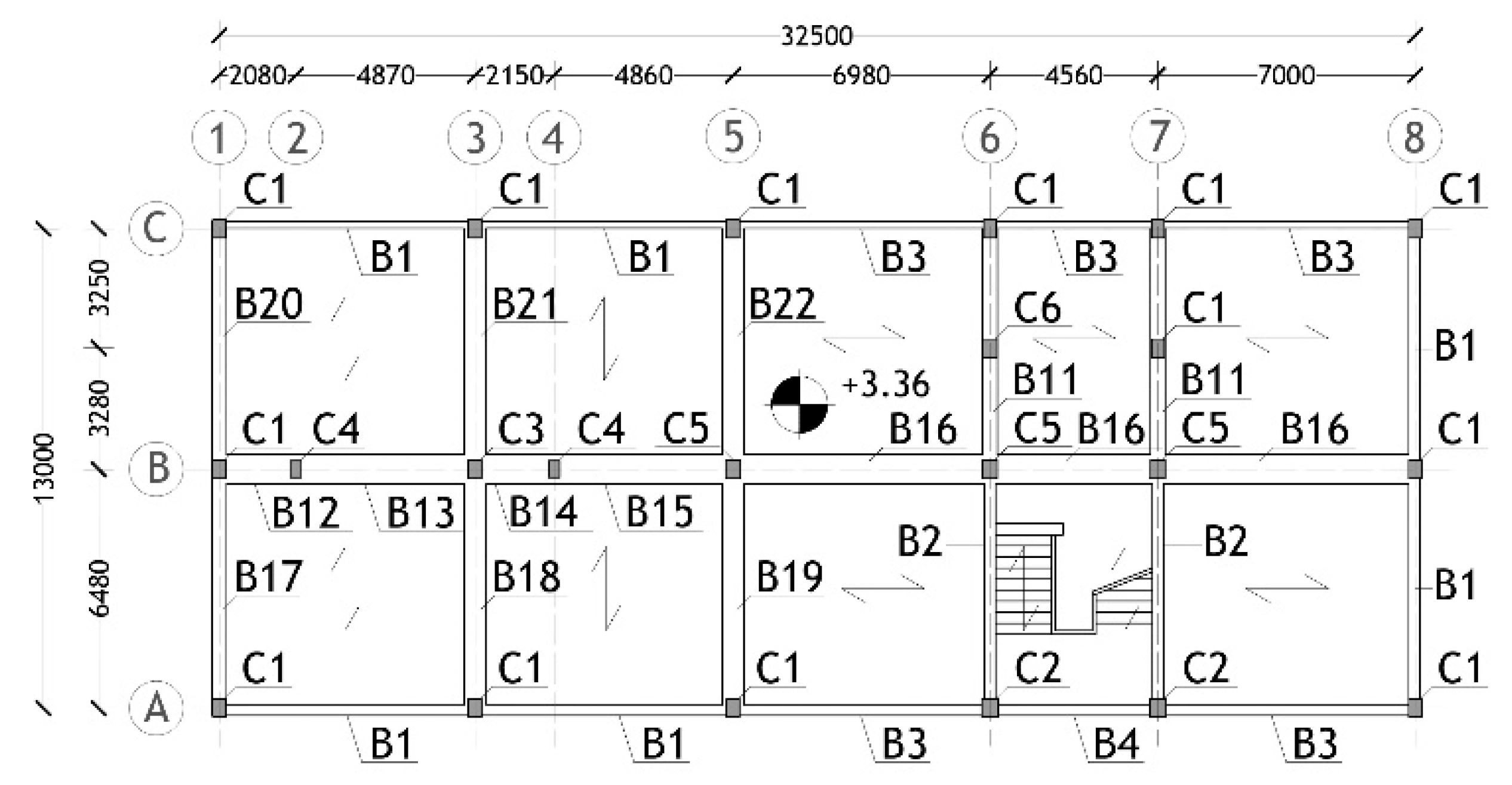
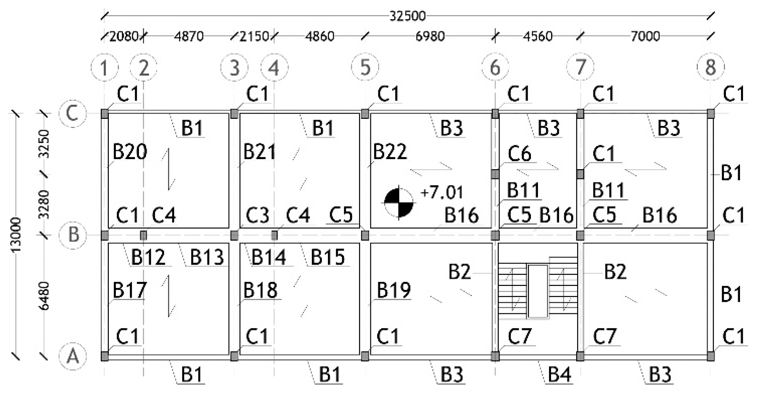
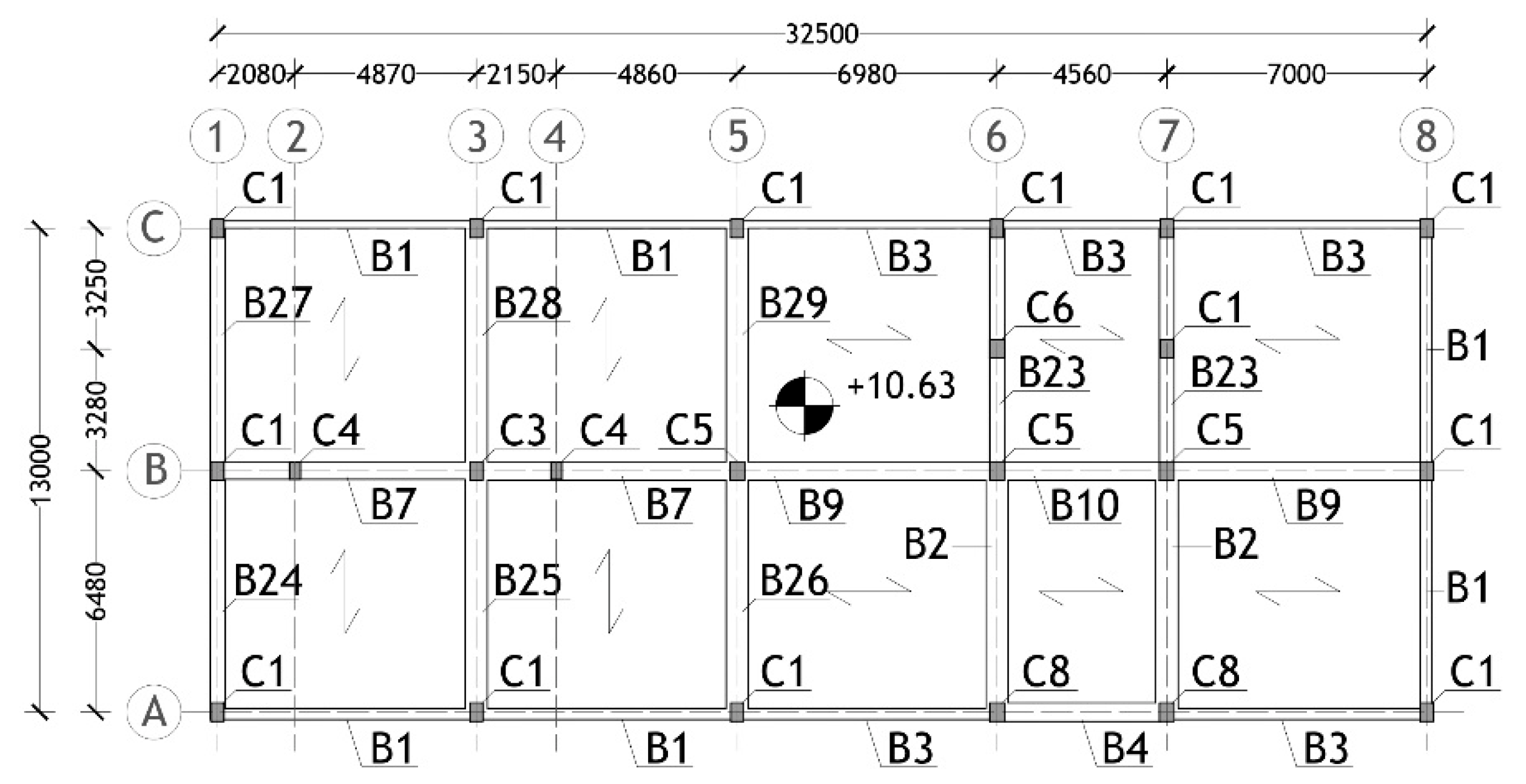
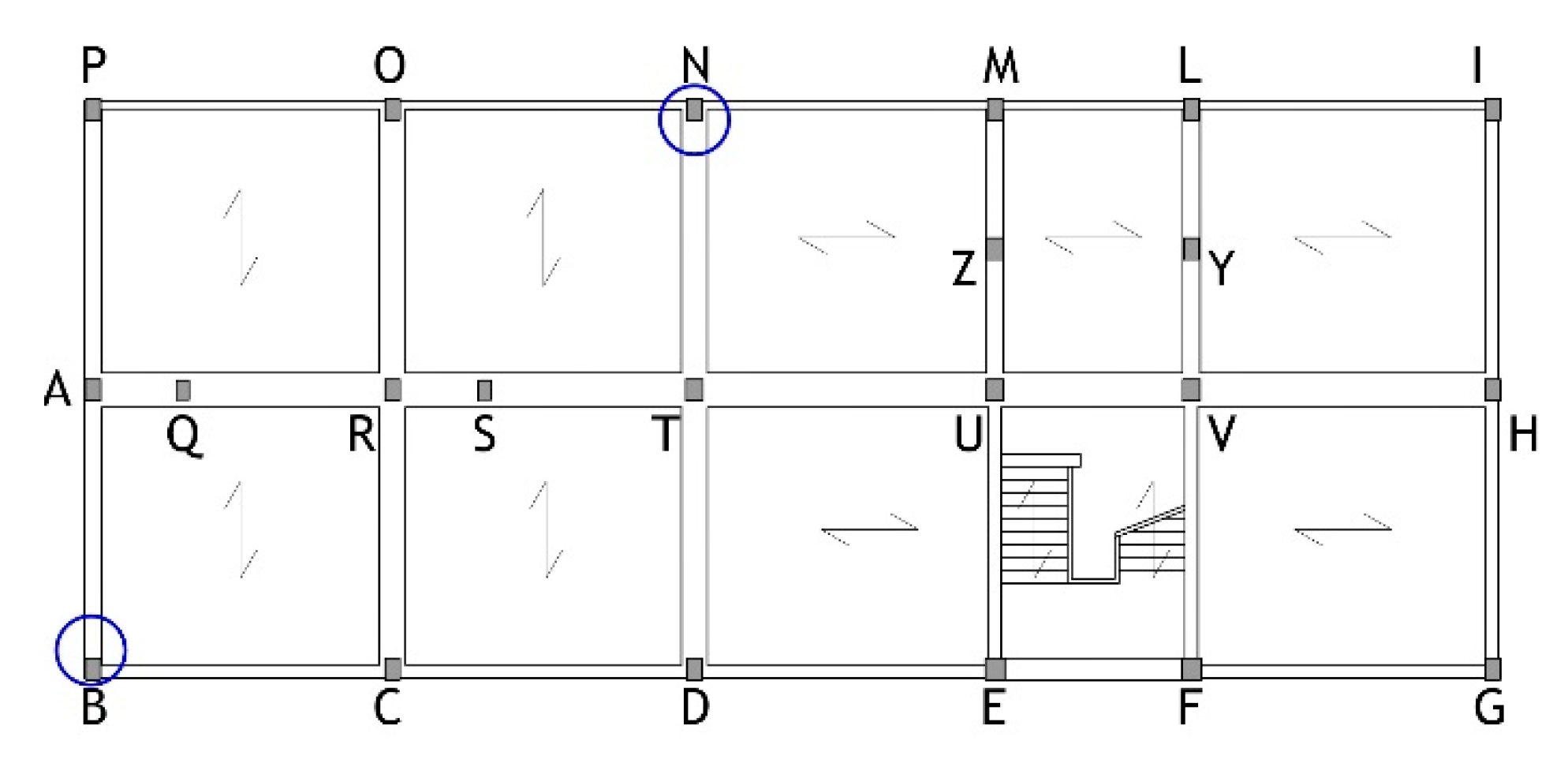
2. Case Study Building

The considered building is a school situated in the town of Tolmezzo, Friuli-Venezia Giulia region, Italy. Its structural design dates back to 1960, and the construction works were completed in 1961. The general characteristics of the building and the results of the seismic assessment analysis carried out in current conditions are summarised below.

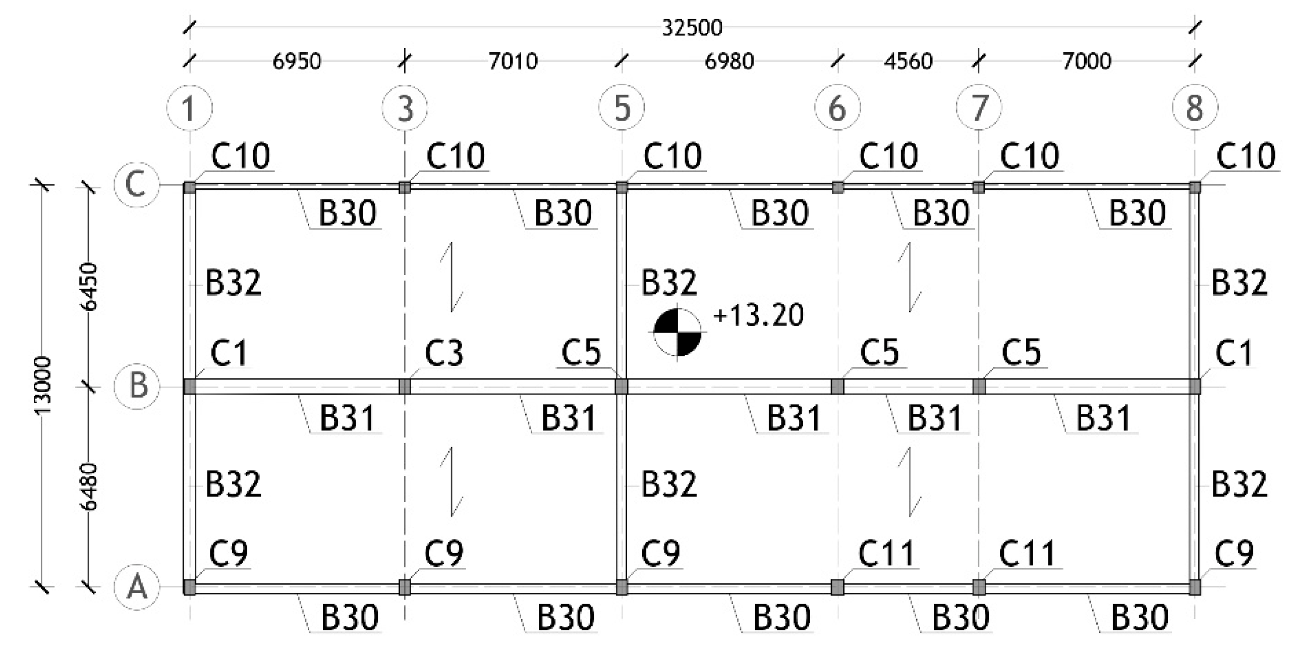
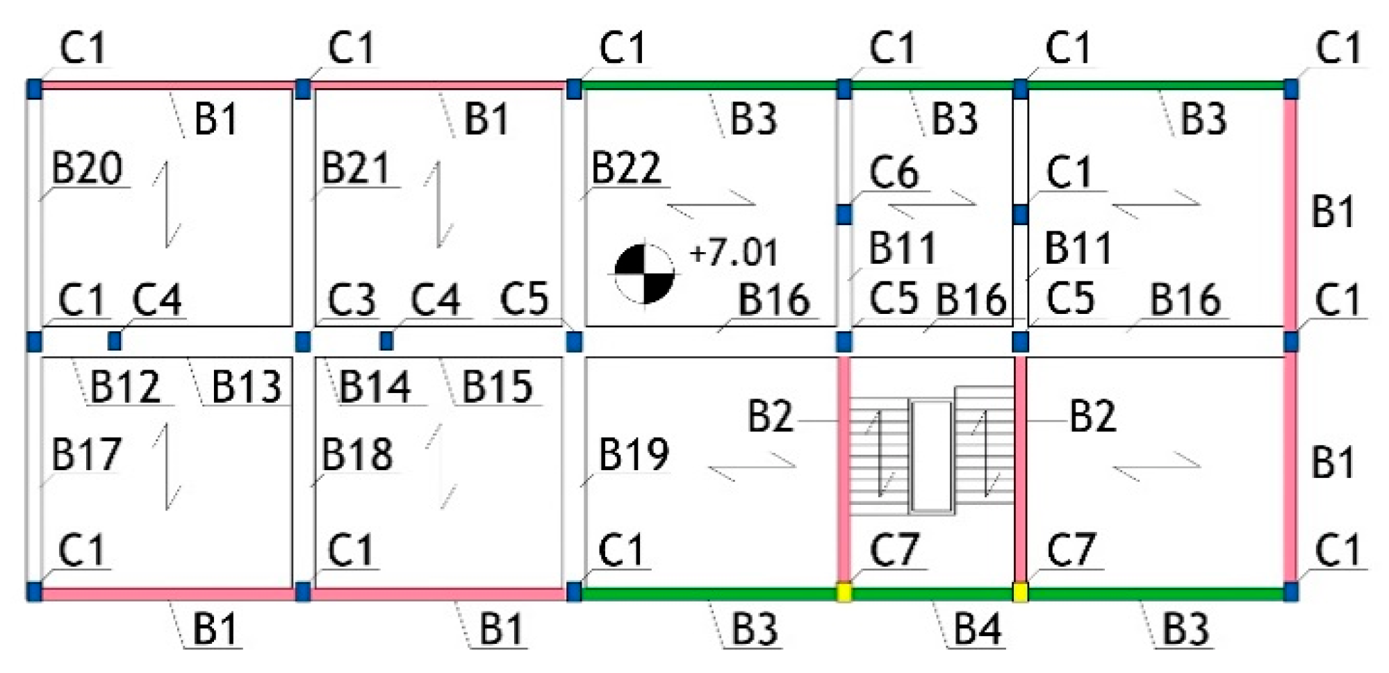
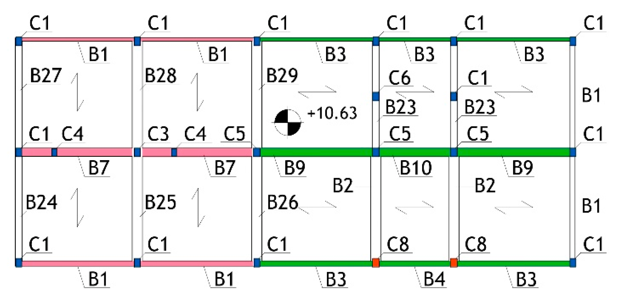
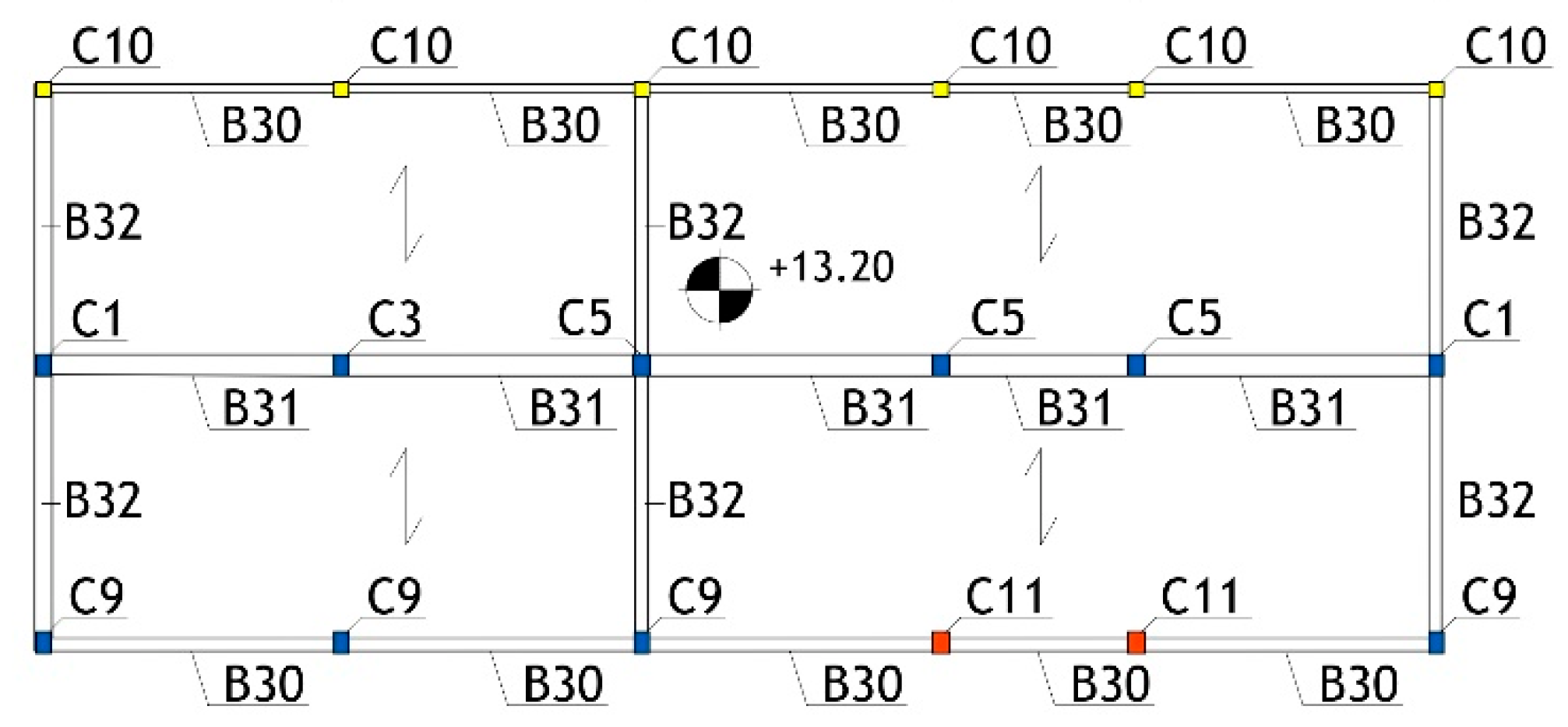
2.1. Geometrical and Structural Characteristics

The building has a rectangular plan, sized 13.5 m × 32.8 m, and is organised in four storeys above ground, with inter-storey heights of 3.36 m (ground storey), 3.65 (first), 3.62 (second), and 2.57 m (measured at the under-roof top). The structural plans of the first, second, and third floors and the roof are shown in Figure 2, Figure 3, Figure 4 and Figure 5.
The structure of the storey floors is made of 280 mm-high and 80 mm-wide RC joists parallel to the transversal direction in plan in the two left frame spans, and parallel to the longitudinal direction in the three remaining frame spans. The joists are placed at a mutual distance of 700 mm, as determined by the interposed clay lug bricks, and a 40 mm thick upper RC slab. The roof floor structure is made of “SAPAL”-type 370 mm-high reinforced clay lug bricks, integrated by on-site cast 350 mm-high RC ribs placed at a mutual distance of 1250 mm, and a 50 mm thick upper RC slab. Foundations are constituted by a mesh of inverse T-beams, with heights and flanges ranging from 700 mm to 1000 mm, and from 600 mm to 800 mm, respectively.
As part of the OSS (Seismic Observatory of Structures) programme promoted by the Italian Department of Civil Protection to structurally assess and monitor public buildings [51], a careful on-site mechanical investigation campaign was carried out on the case study one [52]. This campaign consisted of concrete cover demolitions (Figure 6a), pacometer tests (Figure 6b), and extraction of samples, for the reinforcing bars, and core drillings (Figure 7a) and Son-Reb tests (i.e., combined sclerometer—Figure 7b—and ultrasonic—Figure 7c—tests) for concrete.
The results of the tests highlighted the average values of yielding and ultimate stress values, fsy and fsu, of 380 MPa and 500 MPa, respectively, and Young’s modulus, Es, of 204.000 MPa for steel; and the average values of cylindrical compressive strength, fc, equal to 20.3 MPa, Young’s modulus, Ec, of 21.500 MPa, and strains at peak stress and at collapse, εc, and εcu, equal to 0.00156 and 0.00402, respectively, for concrete.

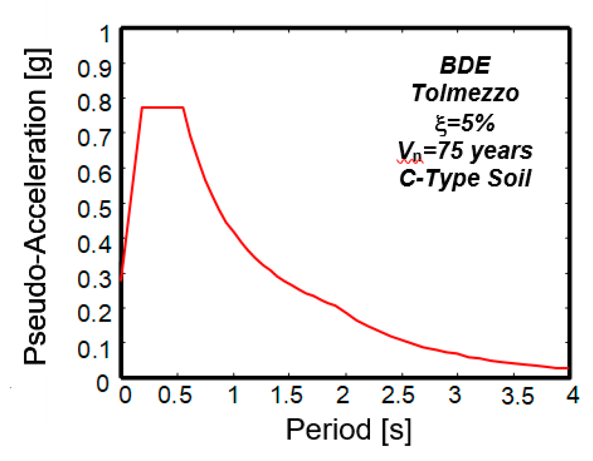
2.2. Time-History Evaluation Analysis

The seismic response of the building was evaluated by means of the finite element model displayed in Figure 8, generated by the SAP2000NL calculus program [53]. Concrete-type frame elements were used to model beams and columns, and shell elements for the flights of stairs. The in-plan axial stiffness of the floors was simulated by means of equivalent horizontal braces. The model does not include infills in contact with the structural members because the assessment analysis was essentially focused on the building performance at the BDE, the peak lateral displacements relevant to which would significantly damage them, as discussed below, thus, practically annulling the contribution of infills to the seismic response.
The finite element model shown in Figure 8 was used for the analysis of the structure both in current state and in ACM-retrofitted conditions; the mechanical characteristics of concrete were changed when passing from the former to the latter, according to the criteria presented in Section 3.
A modal analysis of the structure was carried out in the first step of the assessment study, which highlighted three prevailing modes, and namely: a first translational mode along the longitudinal axis in plan, with vibration period of 0.32 s; and a second and a third mixed translational along the transversal axis in plan-rotational around the vertical axis modes, with periods of 0.23 s and 0.16 s, respectively. Nine modes are needed to obtain a summed effective modal mass greater than 85% of the total seismic mass of the building along the longitudinal (95%) and transversal (87%) axes, as well as around the vertical one (86%).
The non-linear time-history analyses were developed by adopting lumped plastic hinges at the end sections of beams, governed by a Takeda-type hysteretic relationship [54] and fibre-type plastic hinges—composed of concrete-type fibres and steel-type fibres—at the end sections of columns. For the latter, which allow an accurate consideration of the interaction between axial force and biaxial bending moment, a Mander-type [7] backbone curve and a Takeda-type hysteretic model were assumed for the concrete fibres, and a strain hardening elasto-plastic skeleton curve with hysteretic kinematic behaviour for the reinforcing steel fibres. A typical fibre model mesh of a column cross section is drawn in Figure 9, where the reinforcing bars are located by red dots encased in black circles.
The accelerograms used in the input for the time-history analyses were generated in seven groups of two horizontal components from the pseudo-acceleration response spectra referred to the municipality of Tolmezzo. In each analysis, a different pair of horizontal components was used in the input. The results were elaborated in mean terms over the response to the seven pairs. Attention is focused here on the response to the BDE, with a 10% probability of being exceeded over the reference time period VR, fixed at 75 years by Italian Standards for school buildings [55]. The relevant response spectrum, referred to the soil conditions identified for the site of the building, and characterised by a peak ground acceleration of 0.284 g, is shown in Figure 10.
A synthesis of the results of the analyses shows that the members in unsafe conditions are: 54 out of 84 columns in shear (namely, by referring to the plans in Figure 2 through Figure 5, 23 C1, 2 C2, 4 C3, 4 C4, 4 C5, 2 C6, 2 C7, 2 C8, 4 C9, 4 C10, and 2 C11-type columns), and 43 in combined axial force/biaxial flexure (21 C1, 2 C2, 4 C3, 2 C4, 10 C5, 2 C7, and 2 C8), with the maximum demand/capacity ratio (DCR) values of 3.49 (shear) and 2.26 (combined axial force/biaxial flexure); 42 out of 73 beams in shear (14 B1, 4 B2, 15 B3, 3 B4, 4 B7, 1 B9, and 1 B10-type beams), and 32 (14 B1, 4 B2, 13 B3, and 1 B9) in flexure, with the maximum DCRs of 2.6 (shear) and 2.01 (flexure); and 25 out of 60 beam-to-column joints (by referring to the nomenclature reported in Section 3.1, 3 B, 3 D, 3 H, 3 N, 3 P, 2 C, 2 G, 2 I, 2 O, 1 E, and 1 F-type joints), with the maximum DCRs of 2.74. At the same time, safe conditions are evaluated for the foundation beams, both in flexure and shear.
For the example of the plastic demand in columns, the bending moment-rotation cyclic response around the strong flexural axis of C1 column situated in the A5 alignment on the ground storey is plotted in Figure 11 for the most demanding of the seven input accelerograms.
The energy response time-histories of the structure obtained for the same input ground motion are graphed in Figure 12, highlighting a similar contribution of the plastic energy related to the inelastic response of the RC members and the modal (i.e., viscous damping matrix-related) energy dissipated by the structure.
The response in terms of lateral displacements is assessed by the maximum inter-storey drift values equal to about 1.3% of the inter-storey height in the longitudinal direction in plan, and 1.05% in the transversal direction, at the BDE. The corresponding values at the Serviceability Design Earthquake (SDE), characterised by 63% probability of being exceeded over VR, are equal to 0.55% and 0.46%, respectively. Based on these results, negligible damage to non-structural elements (infills, partitions, finishes, and plants) is assessed at the SDE, and repairable damage at the BDE. This highlights an acceptable lateral displacement performance of the building, which does not prompt any interventions aimed at significantly increasing the horizontal translational stiffness of the structure.
In view of this, as well as of the remaining data drawn from the seismic assessment analysis in current conditions, a retrofit strategy aimed at improving the response capacities of beams, columns, and beam-to-column joints by means of local strengthening interventions, like the ACM-based one, was identified as the preferable option for the case study structure.

3. ACM-Based Retrofit Solution

The retrofit hypothesis was designed by computing the effects of the ACM-induced active confinement on the compression strength and ultimate strain of concrete. Relevant calculations were carried out by referring to the formulas provided by the Instructions for application of the Italian Technical Standards [56], recapitulated below.

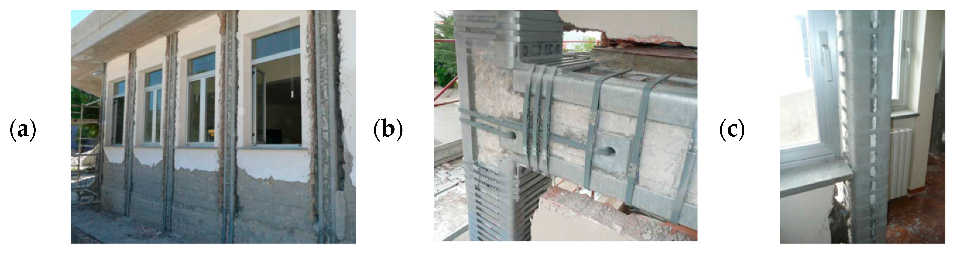
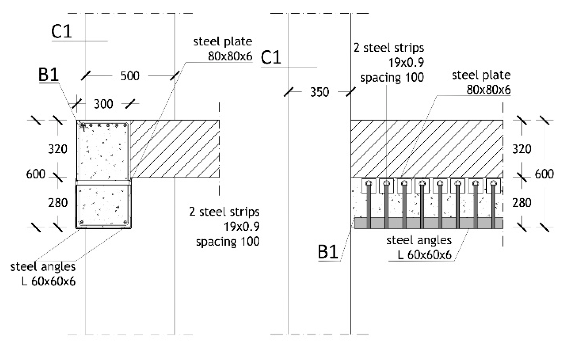
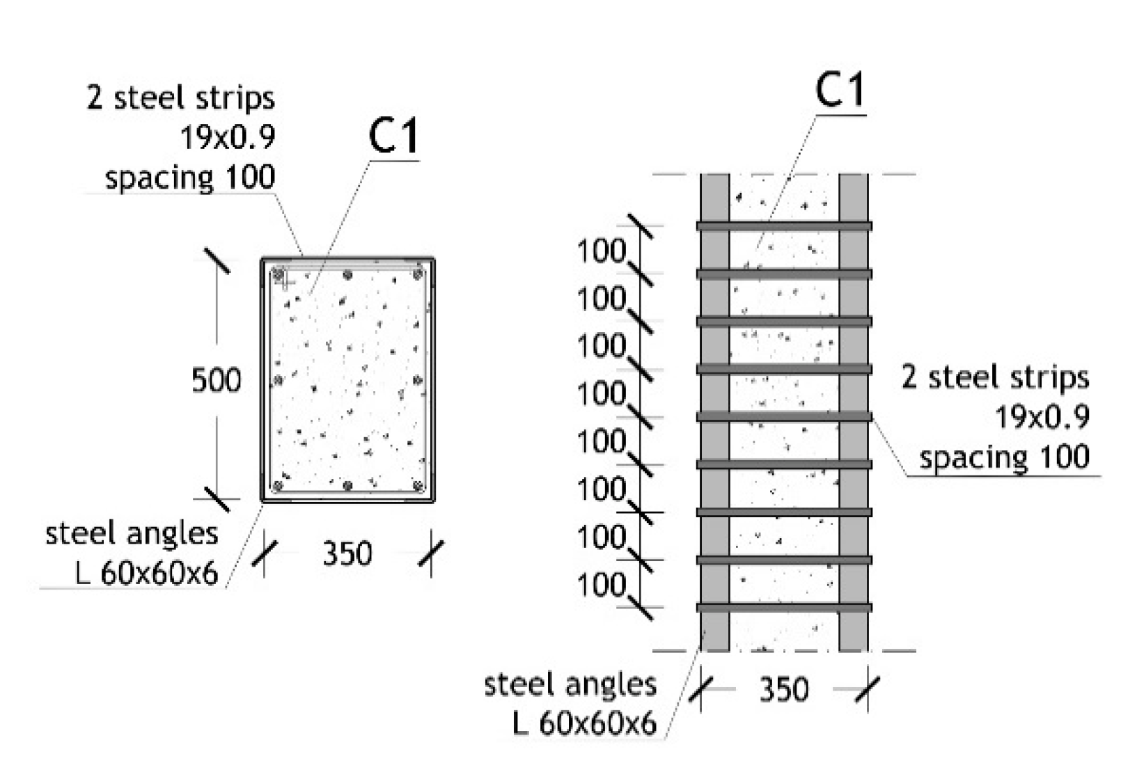
3.1. Beams and Columns

In the following, symbol ρs is assumed to denote the transversal reinforcement volume ratio for discontinuous jacketing made of strips, given by ρs = 2As·(b + h)/(b·h·s), with As, s = transversal section and spacing of strips, b, h = RC section sides, and fywd the design yielding stress of the constituting stainless steel of strips (equal to 560 MPa for the basic ACM application conceived in this study). Based on this notation, the cylindrical compression strength of the confined concrete, fcc, is obtained from the unconfined strength, fc, as follows:
f c c = f c · 1 + 3.7 · 0.5 · α n · α s · ρ s · f y w d f c 0.86
where:
α n = 1 b 2 R 2 + h 2 R 2 3 b · h
α s = 1 s   h s 2 b · 1 s   h s 2 h
with hs = strip height and R = manufacturing smoothing radium, which can be put as equal to:
R = min L a n g ; 5 t a n g
where Lang, tang are the side and thickness of the steel angles. The εcc strain at the peak stress and the εccu ultimate strain of confined concrete are derived from the corresponding εc and εcu values in original unconfined conditions by means of the following relations:
ε c c = ε c · 1 + 5 f c c f c 1
ε c c u = ε c u + 0.5 · 0.5 α n · α s · ρ s · f y w d f c c
When the intervention was designed, a decision was made to place the steel strips at the ends of each column in unsafe conditions, with the number of layers ranging from two to four, and constant spacing of 50 mm or 100 mm. For unsafe beams, two strip layers with a spacing of 100 mm were always adopted. The columns and beams subjected to the interventions are identified with different colours in the structural plans drawn in Figure 13, Figure 14, Figure 15 and Figure 16. Therein, the labels “Full height ACM-strengthened” (in green) and “Web ACM-strengthened” (pink) mean that the lateral side of the strips is either limited to the out-of-depth portion of beams or extended to their whole height.
The fcc, εcc, and εccu values computed by means of Formulas (1), (5) and (6), respectively, are recapitulated in Table 1, for the columns subjected to the intervention, and Table 2, for beams. The fcc values are about 10% to 50% greater than the fc value of 20.3 MPa identified in current conditions, as mentioned in Section 2.1; at the same time, εcc and εccu are about 180% to 415% greater than the corresponding εc and εcu values of 0.00156 and 0.00402, respectively, cited in Section 2.1 as well.
The confinement effects in terms of moment-curvature response are demonstratively visualised in Figure 17 for column C1. Consistently with the results obtained for the compression strength and ultimate strain values, the diagram highlights an increase in peak moment and ultimate curvature equal to about 15% and 160%, respectively. This underlines a considerable improvement of bending moment capacity and a very high growth in ductility reached, thanks to the ACM-induced confinement action.
The bending moment (beams) and axial force-biaxial bending moment (columns) checks in retrofitted conditions were developed by replacing the original properties of concrete with the corresponding ones of confined concrete, for each strengthened member. The results of these checks, not reported in detail for brevity’s sake, show DCR values below one, and, thus, safe conditions, for all beams and columns. Furthermore, plastic demand is reduced by up to 20% in the most stressed members, and by 18% in the complete structure, as highlighted by the hysteretic response of C1 ground storey column in Figure 18 and the energy time-histories in Figure 19, which replicate in retrofitted conditions the corresponding graphs plotted in Figure 11 and Figure 12 for the current state. The reduction in the plastic demand is a consequence of the increased elastic response limits of beams and columns produced by the intervention, in addition to the enhancement of their strength capacities.
In order to develop shear checks on beams and columns, the contribution of the ACM system strips, VRsd,ACM, to the tensile shear strength was evaluated as follows [56]:
V R s d , A C M   = 0.9 · d · 2 t s s · b s · 0.5 f y w d · c o t θ
where d is the effective depth of the RC section, ts and bs are the thickness and width of strips, 0.5 is a reduction factor adopted to guarantee an elastic response of strips—and thus their effectiveness in limiting concrete crack width—with considerable margin, and θ is the angle of inclination of shear cracks with respect to the horizontal. In retrofitted conditions, the resultant shear strength in tension, VRsd,r, is given by the sum of VRsd,ACM and the value in current state, VRsd,c. VRsd,ACM, and VRsd,c are lower than the corresponding values of the shear strength in compression, VRcd,ACM and VRcd,c, computed by considering, in relevant formulas, fc in current state, and fcc in retrofitted conditions. Therefore, the tensile values VRsd,c and VRsd,r were assumed in the stress state checks as shear strength measures. Relevant values are recapitulated in Table 3 and Table 4 for the most stressed columns and beams, along with the shear demand values derived from the analysis, VEd, and the DCR values in current and retrofitted conditions, DCRc and DCRr. As highlighted by Table 3 and Table 4, all members reach safe post-retrofit shear stress states, with the maximum DCRr/DCRc ratios (which give a direct measure of the maximum performance enhancement obtained thanks to the ACM-based intervention) ranging from about 2.8, for beams, to about 10, for columns.
The design drawings of the interventions on beams, both for the case of “Full height” and “Web” ACM-strengthened ones, and columns are illustrated in Figure 20, Figure 21 and Figure 22.

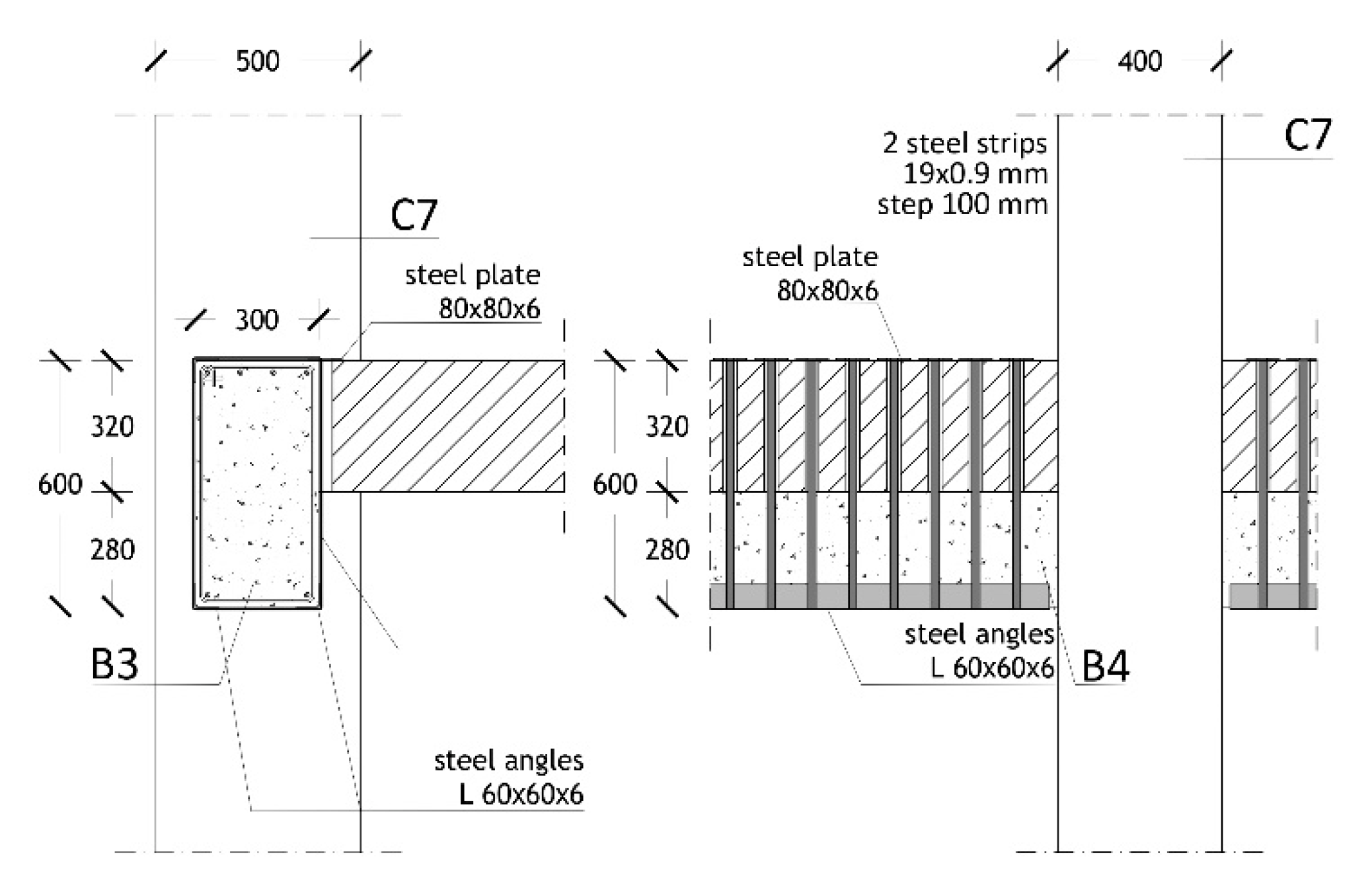
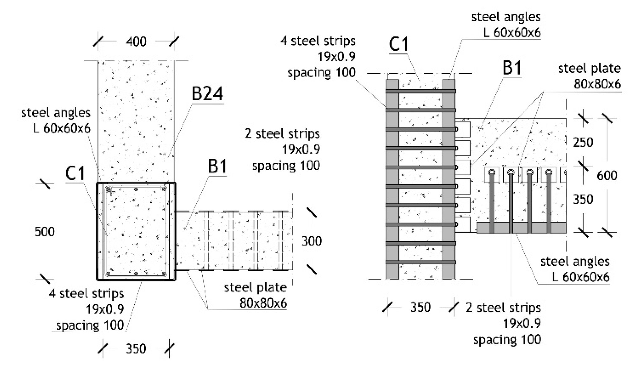
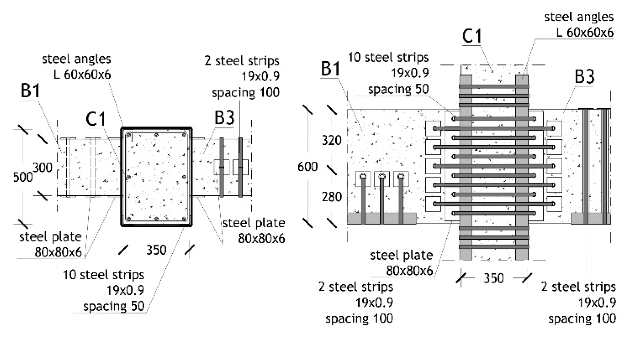
3.2. Beam-to-Column Joints

Stress checks were carried out on all beam-to-column joints, as none of them meet the condition of a geometrically confined joint. According to [56], the two possible collapse mechanisms were evaluated, i.e., in tension and compression, showing that—as mentioned in Section 2—25 out of 60 joints are in unsafe conditions in the current state, with the maximum demand/capacity ratios of 2.74. Based on these results, the ACM system was applied to the unsafe joints too. The checks were replicated in retrofitted configuration, by means of the following relations:
σ n t = N 2 A j + σ h 2 N 2 A j + σ h 2 2 + V n A j 2   0.3 f c c
σ n c = N 2 A j + σ h 2 + N 2 A j σ h 2 2 + V n A j 2 0.5 f c c
where σnt and σnc are the principal tensile and compressive stresses, N is the axial force in the column above the joint, Aj is the area of the joint surface evaluated for the direction along which shear is considered, Vn is the total shear acting on the joint (given by the sum of the shear transmitted by the column above and the horizontal forces transferred by the upper face of the concurrent beams), and σh is the horizontal active confinement pressure exerted by the strips placed on the joint, expressed as follows:
σ h = n c · n s · 2 · A s · f y w d b j · h j w
where nc is the number of strip positions in the joint, ns is the number of layers per each strip, and bj, and hjw are the effective width and height of the joint. The same type of strips as used to strengthen beams and columns was adopted for joints too. The spacing and number of layers per strip were calculated for each unsafe joint in current state by means of expressions (8)–(10). The design drawings of the intervention on the most stressed corner and perimeter joint, both situated in the ground storey and denoted with letters “B” and “N” in Figure 23, are illustrated in Figure 24 and Figure 25. The quantity of strips requested for ground storey joint N (10 strip layers with 50 mm spacing) is the same as for the adjacent joint “O”. All remaining perimeter joints are strengthened with a lower number of strips (from eight to two layers, and with spacing of 50 mm or 100 mm).
The pre- and post-strengthening demand/capacity ratios for a selected set of most stressed joints, listed in Table 5, highlight that safe stress states are reached in retrofitted conditions, like for beams and columns.
The cost of the structural intervention, demolition, and reconstruction of the involved portions of façade infills and partitions included, amount to about 150 Euro/m2, i.e., 25–30% lower than the cost estimated for traditional retrofit strategies, like RC-based jacketing of beams, columns and joints, incorporation of additional earthquake-resistant structural members, etc. The latter strategy would also considerably increase the lateral stiffness of the structure, which is not motivated by the displacement performance in current state and, at the same time, could cause an unfavourable growth of storey shears.
Finishes, like plasters, paintings, and floor tiles are not included in cost computation, as they are included in the architectural renovation works planned for the building. At the same time, no interference with the thermal and electrical plants—and thus no additional related cost—is determined by the installation of the ACM system.

4. Conclusions

The study on the application of the ACM system to reinforced concrete structures presented in this article was aimed at evaluating, for a real building, all the aspects involved in the practical design of this retrofit strategy, as well as the actual levels of seismic improvement that it can offer. Indeed, although the use of the ACM was extended to RC structures several years ago, the literature on this technology is essentially limited to technical reports focused on the calculation of the interventions on single members, and relevant installation details.
The case study selected for this research is representative of the wide class of RC buildings designed in the 1960s without anti-seismic provisions, which causes a considerable earthquake-related vulnerability even when they are characterised by geometrical regularity and a simple and clearly conceived structural organization, like the examined school.
The results of the assessment analyses and the development of the ACM-based design hypothesis are summarised in the concluding remarks listed below.
The response of the structure at the BDE level of seismic action highlights unsafe shear stress states in most beams and columns, with the maximum demand/capacity ratios reaching 2.6 in the former and 3.49 in the latter. Furthermore, about 40% of beams do not meet stress checks in flexure, and more than 50% of columns in normal force/biaxial flexure. About 40% of beam-to-column joints are in unsafe conditions too.
On the other hand, thanks to the structural regularity of the building and to its low number of storeys, the response in terms of inter-storey drifts is not so poor.
As a consequence of the combined stress states/drifts assessment, a local strengthening strategy, like the ACM, was evaluated as the preferable retrofit choice for the building.
Thanks to the active confinement action offered by this technology, the intervention allows reaching a safe response of all members. This is obtained with a relatively small number of strips in all beams (two strip layers with 100 mm spacing) and columns (characterised by the same design output, except for two elements, where four strip layers and a 50 mm spacing are requested).
A comparable quantity of strips is computed for most beam-to-column joints, except for the perimeter ones, where the number of strip layers exceptionally reaches a maximum of 10 for two of them, situated on the ground storey, and eight or six in four other perimeter joints. This is due to the total absence of stirrups and of any type of transversal reinforcement in the joints, which is typical of the RC structures of the time, causing a remarkably poor response capacity in tension in the most stressed ones.
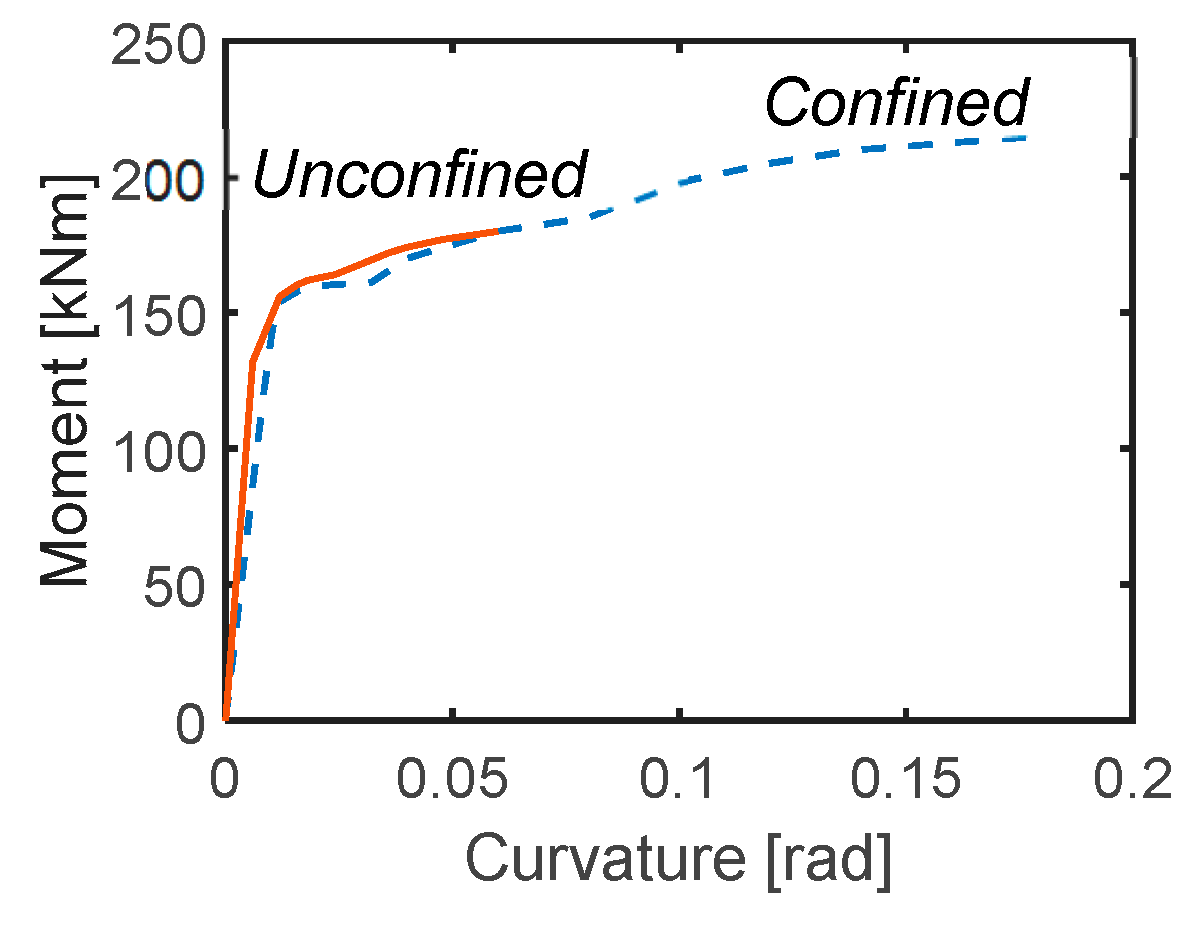
In addition to the effects on strength, the confinement action supplied by the ACM produces remarkable benefits in terms of ductility as well, as quantified by an increase in ultimate curvature in columns always greater than 100%, with the peak of 160%.
The reliable cost analysis of a complete building offered in this study allowed an estimation of the amount of structural works which was 25–30% lower than the cost typically associated to traditional retrofit strategies. This is owed to fewer demolitions, as well as to quicker installation times required by the ACM.
The localization of the intervention inherent to this retrofit strategy, and the practically null increase in the strengthened RC member sections, helps to avoid any appreciable increase in the lateral stiffness of the structural system, and, thus, any related growth in storey shears.
The combined seismic performance enhancement/cost evaluation obtained as a final result of the study confirms the opportunity of a wider application of the ACM method to the seismic retrofit of RC frame structures in the next future.

Author Contributions

Conceptualization, S.S. and G.T.; methodology, S.S., G.T. and E.F.; software, E.F.; validation, S.S., G.T. and E.F.; formal analysis, G.T. and E.F.; investigation, S.S., G.T. and E.F.; resources, G.T.; data curation, G.T. and E.F.; writing—original draft preparation, S.S. and G.T.; writing—review and editing, S.S. and G.T.; funding acquisition, G.T. All authors have read and agreed to the published version of the manuscript.

Funding

Financial support from ReLUIS-DPC Project 2019–2021 (Work Package 15: Normative Contributions for Isolation Project 9–protocol nr. 60–5 February 2019–grant nr. 1100004434, 10.13039/50) is gratefully acknowledged.

Conflicts of Interest

The authors declare no conflict of interest.

Abbreviations

ACMActive Confinement of Masonry (“CAM” in Italian, registered trademark)
ALCactive lateral confinement
PLCpassive lateral confinement
RCreinforced concrete
BDEBasic Design Earthquake
SDEServiceability Design Earthquake
DCRdemand/capacity ratio

References

  1. Thermou, G.E.; Pantazopoulou, S.J. Assessment indices for the seismic vulnerability of existing R.C. buildings. Earthq. Eng. Struct. Dyn. 2011, 40, 293–313. [Google Scholar] [CrossRef]
  2. Sorace, S.; Terenzi, G. Structural assessment of a modern heritage building. Eng. Struct. 2013, 49, 743–755. [Google Scholar] [CrossRef]
  3. Sorace, S.; Terenzi, G. Motion control-based seismic retrofit solutions for a R/C school building designed with earlier Technical Standards. Bull. Earthq. Eng. 2014, 12, 2723–2744. [Google Scholar] [CrossRef]
  4. Richart, F.A.; Brandtzaeg, A.; Brow, R.L. A Study of the Failure of Concrete under Combined Compressive Stress; University of Illinois Engineering Experiment Station Bulletin: Urbana, IL, USA, 1928. [Google Scholar]
  5. Kent, D.C.; Park, R. Flexural members with confined concrete. ASCE J. Struct. Div. 1971, 97, 1969–1990. [Google Scholar] [CrossRef]
  6. Desayi, P.; Iyengar, K.T.S.A.; Reddy, T.S. Equations for stress strain curve of concrete confined in circular steel spiral. Mater. Struct. Test. Res. 1978, 11, 33945. [Google Scholar] [CrossRef]
  7. Mander, J.B.; Priestley, M.J.N.; Park, R. Theoretical stress strain model for confined concrete. ASCE J. Struct. Eng. 1988, 114, 1804–1826. [Google Scholar] [CrossRef] [Green Version]
  8. Saatcioglu, M.; Razvi, S.R. Strength and ductility of confined concrete. ASCE J. Struct. Eng. 1992, 118, 1590–1607. [Google Scholar] [CrossRef]
  9. Uy, B. Strength of reinforced concrete columns bonded with external steel plates. Mag. Concr. Res. 2002, 54, 61–76. [Google Scholar] [CrossRef]
  10. Li, Y.F.; Chen, S.H.; Chang, K.C.; Liu, K.Y. A constitutive model of concrete confined by steel reinforcements and steel jackets. Can. J. Civ. Eng. 2005, 32, 279–288. [Google Scholar] [CrossRef]
  11. Gimenez, E.; Adam, J.M.; Ivorra, S.; Calderon, P.A. Influence of strips configuration on the behavior of axially loaded RC columns strengthened by steel angles and strips. Mater. Des. 2009, 30, 4103–4111. [Google Scholar] [CrossRef]
  12. Montuori, R.; Piluso, V. Reinforced concrete columns strengthened with angles and battens subjected to eccentric load. Eng. Struct. 2009, 31, 539–550. [Google Scholar] [CrossRef]
  13. Nagaprasad, P.; Sahoo, D.P.; Rai, C.D. Seismic strengthening of RC columns using external steel cage. Earthq. Eng. Struct. Dyn. 2009, 38, 1563–1586. [Google Scholar] [CrossRef]
  14. Roca, J.G.; Adam, J.M.; Calderon, P.A. Behavior of RC columns strengthened by steel caging under combined bending and axial loads. Constr. Build. Mater. 2011, 25, 2402–2412. [Google Scholar] [CrossRef]
  15. Wang, L.; Kai-Leung, S.R. Theoretical and experimental study of plate-strengthened concrete columns under eccentric compression loading. ASCE J. Struct. Eng. 2013, 139, 350–359. [Google Scholar] [CrossRef] [Green Version]
  16. Rodriguez, M.; Park, R. Seismic load tests of reinforced concrete columns strengthened by jacketing. ACI Struct. J. 1994, 91, 150–159. [Google Scholar]
  17. Priestley, N.M.J.; Seible, F.; Xiao, Y.; Verma, R. Steel jacket retrofitting of reinforced concrete bridge columns for enhanced shear strength—Part 2: Test results and comparison with theory. ACI Struct. J. 1994, 91, 537–548. [Google Scholar]
  18. Aboutaha, R.S.; Engelhardt, M.D.; Jirsa, J.O.; Kreger, M.E. Retrofit of concrete columns with inadequate lap splices by the use of rectangular steel jackets. Earthq. Spectra 1996, 12, 693–714. [Google Scholar] [CrossRef]
  19. Xiao, Y.; Wu, H. Retrofit of reinforced concrete columns using partially stiffened steel jackets. ASCE J. Struct. Eng. 2003, 129, 725–732. [Google Scholar] [CrossRef]
  20. Kaliyaperumal, G.; Sengupta, A.K. Seismic retrofit of columns in buildings for flexure using concrete jacket. ISET Earthq. Techn. J. 2009, 46, 77–107. [Google Scholar]
  21. Lin, M.N.; Chen, P.C.; Tsai, K.C.; Yu, Y.J.; Liu, J.G. Seismic steel jacketing of rectangular RC bridge columns for the mitigation of lap splice failures. Earthq. Eng. Struct. Dyn. 2010, 39, 1687–1710. [Google Scholar] [CrossRef]
  22. Belal, M.F.; Mohamed, H.M.; Morad, S.A. Behavior of reinforced concrete columns strengthened by steel jacket. HBRC J. 2015, 11, 201–212. [Google Scholar] [CrossRef] [Green Version]
  23. Júlio, E.S.; Branco, F.; Silva, V.D. Structural rehabilitation of columns with reinforced concrete jacketing. Prog. Struct. Eng. Mater. 2003, 5, 29–37. [Google Scholar] [CrossRef] [Green Version]
  24. Bousias, S.N.; Biskinis, D.E.; Fardis, M.N. Strength, stiffness and cyclic deformation capacity of concrete jacketed members. ACI Struct. J. 2007, 104, 521–531. [Google Scholar]
  25. Vandoros, K.G.; Dritsos, S.E. Concrete jacket construction detail effectiveness when strengthening RC columns. Constr. Build. Mater. 2008, 22, 264–276. [Google Scholar] [CrossRef]
  26. Sezen, H.; Miller, E.A. Experimental evaluation of axial behavior of strengthened circular reinforced-concrete columns. J. Bridge Eng. 2011, 16, 238–247. [Google Scholar] [CrossRef]
  27. Foti, D.; Vacca, S. Mechanical behavior of concrete columns reinforced with rheoplastic mortar. Mater. Constr./Build. Mater. 2013, 63, 267–282. [Google Scholar] [CrossRef] [Green Version]
  28. Lorenzis, L.D.; Tepfers, R. Comparative study of models on confinement of concrete cylinders with fiber-reinforced polymer composites. ASCE J. Compos. Constr. 2003, 7, 21937. [Google Scholar] [CrossRef]
  29. Xiao, Y.; Wu, H. Compressive behavior of concrete confined by carbon fiber composite jackets. J. Mater. Civ. Eng. 2000, 12, 13946. [Google Scholar] [CrossRef]
  30. Ilki, A.; Peker, O.; Karamuk, E.; Demir, C.; Kumbasar, N. FRP retrofit of low and medium strength circular and rectangular reinforced concrete columns. J. Mater. Civ. Eng. 2008, 20, 169–188. [Google Scholar] [CrossRef]
  31. Rousakis, T.C.; Karabinis, A.I. Adequately FRP confined reinforced concrete columns under axial compressive monotonic or cyclic loading. RILEM Mater. Struct. 2012, 45, 957–975. [Google Scholar] [CrossRef]
  32. Mazza, F.; Mazza, M. Seismic retrofitting of gravity-loads designed r.c. framed buildings combining CFRP and hysteretic damped braces. Bull. Earthq. Eng. 2019, 17, 3423–3445. [Google Scholar] [CrossRef]
  33. Madotto, R.; Van Engelen, N.C.; Das, S.; Russo, G.; Pauletta, M. Shear and flexural strengthening of RC beams using BFRP fabrics. Eng. Struct. 2021, 229, 111606. [Google Scholar] [CrossRef]
  34. Rossi, E.; Randl, N.; Mészöly, T.; Harsányi, P. Flexural strengthening with fiber-/textile-reinforced concrete. ACI Struct. J. 2021, 118, 97–107. [Google Scholar]
  35. Krstulovic-Opara, N.; Thiedeman, P.D. Active confinement of concrete members with self-stressing composites. ACI Struct. J. 2000, 97, 297–308. [Google Scholar]
  36. Triantafillou, T.C. Seismic retrofitting of structures with fibre-reinforced polymers. Prog. Struct. Eng. Mater. 2001, 3, 57–65. [Google Scholar] [CrossRef]
  37. Mortazavi, A.; Pilakoutas, K.; Son, K.S. RC column strengthening by lateral pre-tensioning of FRP. Constr. Build. Mater. 2003, 17, 491–497. [Google Scholar] [CrossRef] [Green Version]
  38. Saatcioglu, M.; Yalcin, C. External prestressing of concrete columns for improved seismic shear resistance. ASCE J. Struct. Eng. 2003, 129, 105770. [Google Scholar] [CrossRef]
  39. Tamuzs, V.; Tepfers, R.; Chi-Sang, Y.; Rousakis, T.; Repelis, I.; Skruls, V.; Vilks, U. Behaviour of concrete cylinders confined by carbon-composite tapes and prestressed yarns. 1—Experimental data. Mech. Compos. Mater. 2006, 42, 13–32. [Google Scholar] [CrossRef]
  40. Janke, L.; Czaderski, C.; Ruth, J.; Motavalli, M. Experiments on the residual load-bearing capacity of prestressed confined concrete columns. Eng. Struct. 2009, 31, 2247–2256. [Google Scholar] [CrossRef]
  41. Andrawes, B.; Shin, M.; Wierschem, N. Active confinement of reinforced concrete bridge columns using shape memory alloys. ASCE J. Bridge Eng. 2010, 15, 81–89. [Google Scholar] [CrossRef]
  42. Choi, E.; Nam, T.-H.; Yoon, S.J.; Cho, S.K.; Park, J. Confining jackets for concrete cylinder using NiTiNb and NiTi shape memory alloys wires. Phys. Scr. 2010, T139, 014058. [Google Scholar] [CrossRef]
  43. Shin, M.; Andrawes, B. Experimental investigation of actively confined concrete using shape memory alloys. Eng. Struct. 2010, 32, 656–664. [Google Scholar] [CrossRef]
  44. Zuboski, G.R. Stress-Strain Behaviour for Actively Confined Concrete Using Shape Memory Alloys. Master’s Thesis, Department of Civil Engineering, The Ohio State University, Columbus, OH, USA, 2013. [Google Scholar]
  45. Holmes, N.; Niall, D.; O’Shea, C. Active confinement of weakened concrete columns. Mater. Struct. 2015, 48, 2759–2777. [Google Scholar] [CrossRef] [Green Version]
  46. Tran, H.; Balandraud, X.; Destrebecq, J.F. Improvement of the mechanical performances of concrete cylinders confined actively or passively by means of SMA wires. Arch. Civ. Mech. Eng. 2015, 15, 292–299. [Google Scholar] [CrossRef]
  47. Fakharifar, M.; Chen, G.; Wu, C.; Shamsabadi, A.; ElGawady, M.A.; Dalvand, A. Rapid repair of earthquake-damaged RC columns with prestressed steel jackets. J. Bridge Eng. 2016, 21, 4015075. [Google Scholar] [CrossRef]
  48. Abdelrahman, K.; El-Hacha, R. Experimental investigation of RC columns confined with Ni–Ti shape memory alloy wires versus CFRP sheets. Can. J. Civ. Eng. 2021, 48, 925–940. [Google Scholar] [CrossRef]
  49. Dolce, M.; Nigro, D.; Ponzo, F.C.; Marnetto, R. The CAM system for the retrofit of masonry structures. In Proceedings of the 7th International Seminar on Seismic Isolation, Passive Energy Dissipation and Active Control of Vibrations of Structures, Assisi, Italy, 2–5 October 2001; p. 9. [Google Scholar]
  50. Marnetto, R.; Vari, A.; Leonori, M. Il Sistema CAM—Consolidamento Strutturale Con Cuciture Inox; 21mo Secolo: Milan, Italy, 2017. (In Italian) [Google Scholar]
  51. Dolce, M.; Nicoletti, M.; De Sortis, A.; Marchesini, S.; Spina, D.; Talanas, F. Osservatorio Sismico delle Strutture: The Italian structural seismic monitoring network. Bull. Earthq. Eng. 2017, 15, 621–641. [Google Scholar] [CrossRef] [Green Version]
  52. Dipartimento della Protezione Civile. Available online: https://www.protezionecivile.gov.it (accessed on 22 September 2021).
  53. SAP2000NL. Theoretical and Users’ Manual; Computers & Structures Inc.: Berkeley, CA, USA, 2021. [Google Scholar]
  54. Takeda, T.; Sozen, M.A.; Nielsen, N.N. Reinforced concrete response to simulated earthquakes. ASCE J. Struct. Div. 1970, 96, 2557–2573. [Google Scholar] [CrossRef]
  55. Ministry of Infrastructure and Transport. Update of Technical Standards for Constructions; Ministerial Decree, 17 January 2018, Ordinary supplement to G.U. no. 42, 20 February 2018; Ministry of Infrastructure and Transport: Rome, Italy, 2018. (In Italian) [Google Scholar]
  56. Ministry of Infrastructure and Transport. Instructions for the application of the Update of Technical Standards for Constructions; Circular no. 7, 21 January 2019, Ordinary supplement to G.U. no. 35; Ministry of Infrastructure and Transport: Rome, Italy, 2019. (In Italian) [Google Scholar]
Figure 1. Images of a typical ACM-based retrofit intervention on a building with RC frame structure: view of a façade (a), a beam-to-column joint (b), and a column situated in proximity to two windows (c)—pictures taken from [50].
Buildings 11 00575 g001
Figure 2. First floor structural plan.
Buildings 11 00575 g002
Figure 3. Second floor structural plan.
Buildings 11 00575 g003
Figure 4. Third floor structural plan.
Buildings 11 00575 g004
Figure 5. Roof structural plan.
Buildings 11 00575 g005
Figure 6. Images of a concrete cover demolition (a) and a pacometer test (b).
Buildings 11 00575 g006
Figure 7. Images of a concrete core drilling (a), a sclerometer test (b), and an ultrasonic test (c).
Buildings 11 00575 g007
Figure 8. Finite element model of the structure.
Buildings 11 00575 g008
Figure 9. Fibre model of a column cross section.
Buildings 11 00575 g009
Figure 10. BDE-scaled pseudo-acceleration response spectrum for Tolmezzo.
Buildings 11 00575 g010
Figure 11. Bending moment-rotation response of C1 ground storey column belonging to A5 alignment around its strong flexural axis.
Buildings 11 00575 g011
Figure 12. Energy time-histories of the structure.
Buildings 11 00575 g012
Figure 13. Localization of the interventions—ground storey—and nomenclature for all storeys.
Buildings 11 00575 g013
Figure 14. Localization of the interventions—first storey.
Buildings 11 00575 g014
Figure 15. Localization of the interventions—second storey.
Buildings 11 00575 g015
Figure 16. Localization of the interventions—third storey.
Buildings 11 00575 g016
Figure 17. Bending moment-curvature diagram for C1 column referred to its strong flexural axis.
Buildings 11 00575 g017
Figure 18. Bending moment-rotation response of C1 ground storey column belonging to A5 alignment around its strong flexural axis in retrofitted conditions.
Buildings 11 00575 g018
Figure 19. Energy time-histories of the structure in retrofitted conditions.
Buildings 11 00575 g019
Figure 20. Full height ACM-strengthened beam.
Buildings 11 00575 g020
Figure 21. Web ACM-strengthened beam.
Buildings 11 00575 g021
Figure 22. ACM-strengthened column.
Buildings 11 00575 g022
Figure 23. Numbering of beam-to-column joints.
Buildings 11 00575 g023
Figure 24. ACM-strengthened ground storey beam-to-column joint B.
Buildings 11 00575 g024
Figure 25. ACM-strengthened ground storey beam-to-column joint N.
Buildings 11 00575 g025
Table 1. Mechanical parameters of confined concrete—columns.
Column TypeStrips (Layers/Spacing)fcc
(MPa)
εccεccu
C12/100 mm22.650.003140.01136
C22/50 mm24.770.004130.01859
C32/100 mm22.670.003150.01141
C42/100 mm22.920.003270.01231
C52/100 mm22.590.003110.01113
C62/100 mm22.590.003110.01113
C74/50 mm28.580.006060.03072
C82/100 mm24.880.004230.01914
C92/100 mm23.250.003430.01348
C104/50 mm31.310.007390.03813
C112/50 mm25.920.004740.02257
Table 2. Mechanical parameters of confined concrete—beams.
Beam TypeStrips (Layers/Spacing)fcc
(MPa)
εccεccu
B12/100 mm23.790.00370.01541
B22/100 mm24.140.003850.01663
B3/B42/100 mm23.430.003520.01414
B72/100 mm22.580.00310.01109
B9/B102/100 mm22.570.003020.01048
Table 3. Shear demand, capacity values in current and retrofitted conditions, and relevant demand/capacity DCR ratios–selected columns.
ColumnStoreyVEd (kN)VRsd,c (kN)VRsd,r (kN)DCRcDCRr
C1Ground113.459.8275.31.900.41
C2Ground287.299.7530.62.880.54
C4Ground105.253.6247.51.960.43
C1185.659.8275.31.430.31
C31110.474.7290.21.480.38
C4182.666.9260.91.230.32
C71186.978.9653.72.370.29
C82117.978.9423.61.490.28
C103143.741.1435.23.490.33
Table 4. Shear demand, capacity values in current and retrofitted conditions, and relevant demand/capacity DCR ratios–selected beams.
BeamStoreyVEd (kN)VRsd,c (kN)VRsd,r (kN)DCRcDCRr
B1Ground137.872.3192.91.910.71
B2Ground125.659.8137.42.600.91
B11121.572.3192.91.680.63
B21132.159.8137.42.360.96
B7284.559.8167.51.410.51
Table 5. Demand/capacity DCR ratios—selected beam-to-column joints.
Joint TypeStoreyDCRcDCRr
C12.250.97
H12.000.96
N12.230.94
O11.950.93
P11.470.89
B22.740.99
E22.250.90
F22.140.94
Publisher’s Note: MDPI stays neutral with regard to jurisdictional claims in published maps and institutional affiliations.

