
Fire Protection of Steel Structures with Epoxy Coatings under Cryogenic Exposure


Abstract
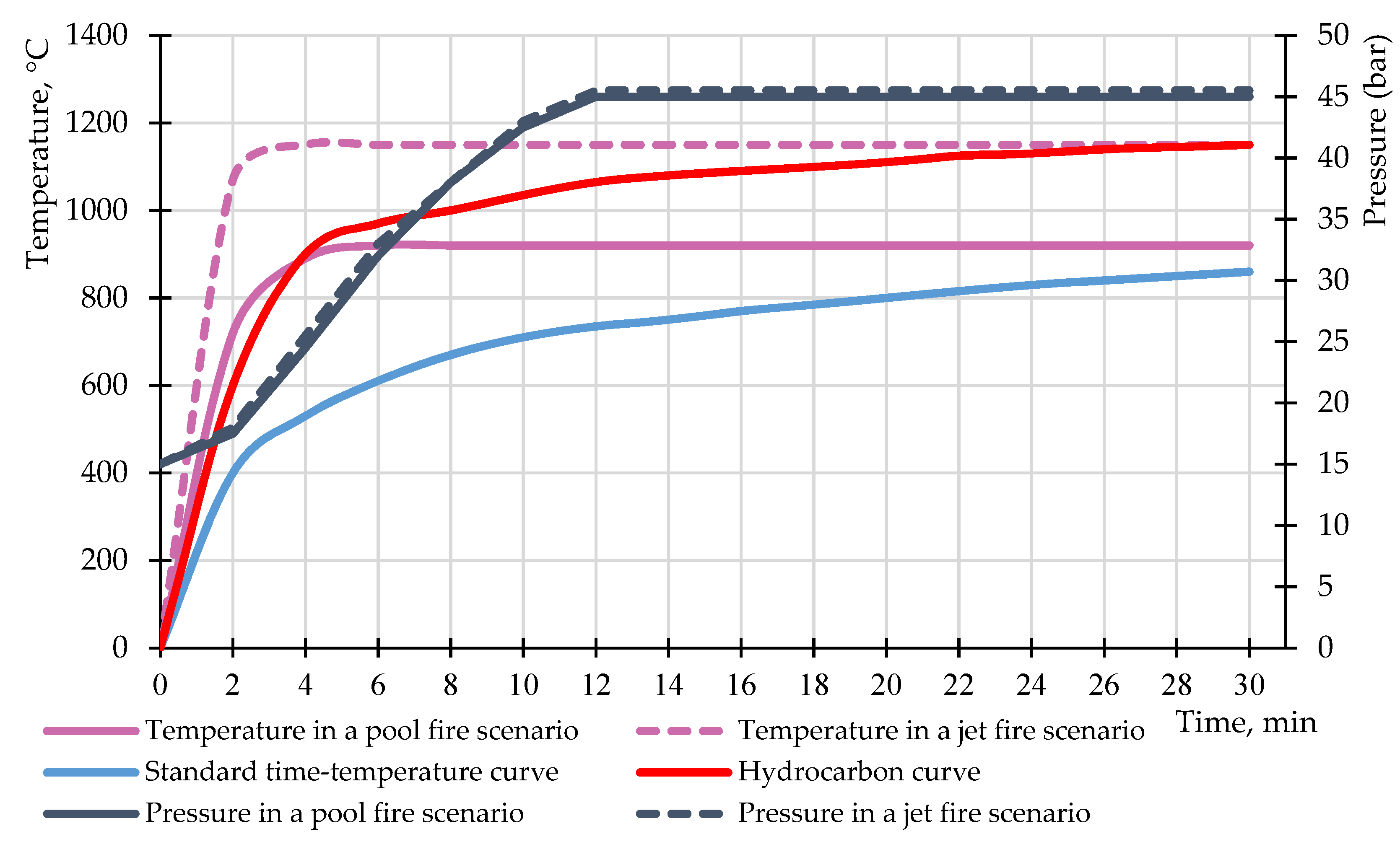
:1. Introduction
2. Materials and Methods
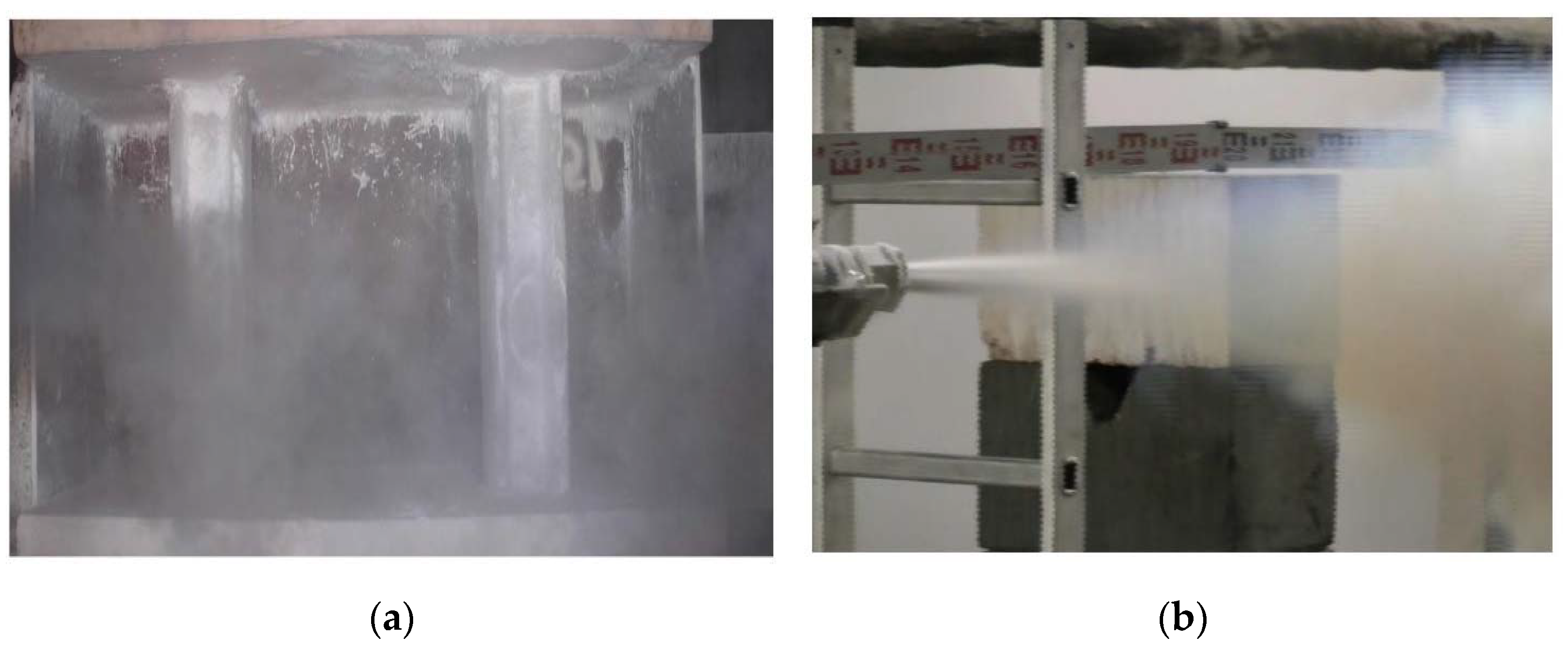
2.1. Experiment No. 1
2.2. Experiment No. 2
2.3. Experiment No. 3
3. Results
3.1. The Results of Experiment No. 1
3.2. The Results of Experiment No. 2
3.3. The Results of Experiment No. 3
4. Discussion
5. Conclusions
Author Contributions
Funding
Institutional Review Board Statement
Informed Consent Statement
Data Availability Statement
Conflicts of Interest
References
- Morgunova, M. The Role of the Socio-Technical Regime in the Sustainable Energy Transition: A Case of the Eurasian Arctic. Extr. Ind. Soc. 2021, 8, 100939. [Google Scholar] [CrossRef]
- Mojarad, A.A.S.; Atashbari, V.; Tantau, A. Challenges for Sustainable Development Strategies in Oil and Gas Industries. In Proceedings of the International Conference on Business Excellence, Bucharest, Romania, 22–23 March 2018; Volume 12. [Google Scholar]
- Gravit, M.; Zimin, S.; Lazarev, Y.; Dmitriev, I.; Golub, E. Fire Simulation of Bearing Structures for Natural Gas Module Plant. In Proceedings of the Advances in Intelligent Systems and Computing, AISC, Novosibirsk, Russia, 25–29 May 2020; Volume 1116. [Google Scholar]
- Dong, J.; Jing, C.; Wen, H.; Tu, M.; Li, J. Predicting the Vaporization Rate of a Spreading Cryogenic Liquid Pool on Concrete Using an Improved 1-D Heat Conduction Equation. Heat Mass Transf. 2021, 1–14. [Google Scholar] [CrossRef]
- Lee, S.; Long, N.V.D.; Lee, M. Design and Optimization of Natural Gas Liquefaction and Recovery Processes for Offshore Floating Liquefied Natural Gas Plants. Ind. Eng. Chem. Res. 2012, 51, 10021–10030. [Google Scholar] [CrossRef]
- Hightower, M.; Gritzo, L.; Luketa-hanlin, A.; Covan, J.; Tieszen, S.; Irwin, M.; Kaneshige, M.; Melof, B.; Morrow, C.; Ragland, D. Guidance on Risk Analysis and Safety Implications of a Large Liquefied Natural Gas (LNG) Spill Over Water; U.S. Department of Energy Office of Scientific and Technical Information: Oak Ridge, TN, USA, 2004. [Google Scholar] [CrossRef] [Green Version]
- Reid, M. The Piper Alpha Disaster: A Personal Perspective with Transferrable Lessons on the Long-Term Moral Impact of Safety Failures. ACS Chem. Health Saf. 2020, 27, 88–95. [Google Scholar] [CrossRef]
- McClain, C.R.; Nunnally, C.; Benfield, M.C. Persistent and Substantial Impacts of the Deepwater Horizon Oil Spill on Deep-Sea Megafauna. R. Soc. Open Sci. 2019, 6, 191164. [Google Scholar] [CrossRef] [Green Version]
- EN 1363-2:1999. Fire Resistance Tests—Part 2: Alternative and Additional Procedures. Available online: https://nd.gostinfo.ru/document/6239985.aspx (accessed on 10 August 2021).
- Gravit, M.V.; Golub, E.V.; Antonov, S.P. Fire Protective Dry Plaster Composition for Structures in Hydrocarbon Fire. Mag. Civ. Eng. 2018, 79, 86–94. [Google Scholar] [CrossRef]
- Gravit, M.; Golub, E.; Klementev, B.; Dmitriev, I. Fire Protective Glass Fiber Reinforced Concrete Plates for Steel Structures under Different Types of Fire Exposure. Buildings 2021, 11, 187. [Google Scholar] [CrossRef]
- Gravit, M.; Gumerova, E.; Bardin, A.; Lukinov, V. Increase of Fire Resistance Limits of Building Structures of Oil-and-Gas Complex Under Hydrocarbon Fire. Adv. Intell. Syst. Comput. 2018, 692, 818–829. [Google Scholar] [CrossRef]
- Guoqiang, L.; Peijun, W. Properties of Steel at Elevated Temperatures. In Advanced Analysis and Design for Fire Safety of Steel Structures; Springer International Publishing: New York, NY, USA, 2013; pp. 37–65. [Google Scholar] [CrossRef]
- CEN-EN 1473. Installation and Equipment for Liquefied Natural Gas—Design of Onshore Installations. Available online: https://standards.iteh.ai/catalog/standards/sist/e156d980-096f-4fad-92f9-a0e38801f459/sist-en-1473-2021 (accessed on 24 August 2021).
- NFPA 59A. Standard for the Production, Storage, and Handling of Liquefied Natural Gas (LNG). Available online: https://www.nfpa.org/codes-and-standards/all-codes-and-standards/list-of-codes-and-standards/detail?code=59A (accessed on 24 August 2021).
- Health & Safety Programs. Campus Safety University of Lethbridge. Cryogen Safety. Available online: https://www.ulethbridge.ca/sites/default/files/2020/09/Cryogen%20Safety%20Manual%20May%202018_0.pdf (accessed on 29 August 2021).
- Vancouver Coastal Health Research Institute. Liquid Nitrogen Hazards. Available online: http://www.vchri.ca/sites/default/files/LiquidNitrogenHazards_23June2011.pdf (accessed on 29 August 2021).
- Nazarpour, F.; Wen, J.; Dembele, S.; Udechukwu, I.D. LNG Vapour Cloud Dispersion Modelling and Simulations with OpenFOAM. Chem. Eng. Trans. 2016, 48, 967–972. [Google Scholar] [CrossRef]
- Lepov, V.; Grigoriev, A.; Bisong, M.S.; Lepova, K. Brittle Fracture Modeling for Steel Structures Operated in the Extreme. Procedia Struct. Integr. 2017, 5, 777–784. [Google Scholar] [CrossRef]
- Bukowski, J.; Liu, Y.N.; Boccella, S.; Kowalski, L. Innovations in Natural Gas Liquefaction Technology for Future Lng Plants and Floating LNG Facilities. Int. Gas Res. Conf. Proc. 2011, 1, 605–631. [Google Scholar]
- Andreasen, A.; Borroni, F.; Nieto, M.Z.; Stegelmann, C.; Nielsen, R.P. On the Adequacy of API 521 Relief-Valve Sizing Method for Gas-Filled Pressure Vessels Exposed to Fire. Safety 2018, 4, 11. [Google Scholar] [CrossRef] [Green Version]
- Guidance Notes for Risk Based Analysis: Cryogenic Spill. Available online: https://ru.scribd.com/document/296047673/LR-Guidance-for-Cryogenic-Spill (accessed on 20 August 2021).
- Hiroya, Y.; Tanabe, M.; Kataoka, S.; Yamada, Y.; Miyashita, T. Simplified Method to Define the Cryogenic Spill Hazard in LNG Liquefaction Facility. Chem. Eng. Trans. 2019, 77, 505–510. [Google Scholar] [CrossRef]
- Mikalsen, R.F.; Glansberg, K.; Wormdahl, E.D.; Stolen, R. Jet fires and cryogenic spills: How to document extreme industrial incidents. In Proceedings of the Sixth Magdeburg Fire and Explosion Days Conference Proceedings, Magdeburg, Germany, 25–26 March 2019; pp. 1–6. [Google Scholar]
- Gravit, M.; Gumenyuk, V.; Sychov, M.; Nedryshkin, O. Estimation of the Pores Dimensions of Intumescent Coatings for Increase the Fire Resistance of Building Structures. In Proceedings of the Procedia Engineering, St. Petersburg, Russia, 18–20 March 2015; Volume 117. [Google Scholar]
- Fireproofing for Hydrocarbon Fire Exposures // GAPS Guidelines. Publication of Global Asset Protection Services LLC. 2000. Available online: https://www.appliedbuildingtech.com/system/files/gap2.5.1.fireproofingforhydrocarbonexposures.pdf (accessed on 24 August 2021).
- Lucherini, A.; Maluk, C. Assessing the Onset of Swelling for Thin Intumescent Coatings under a Range of Heating Conditions. Fire Saf. J. 2019, 106, 1–12. [Google Scholar] [CrossRef]
- Zeng, Y.; Weinell, C.E.; Dam-Johansen, K.; Ring, L.; Kiil, S. Exposure of Hydrocarbon Intumescent Coatings to the UL1709 Heating Curve and Furnace Rheology: Effects of Zinc Borate on Char Properties. Prog. Org. Coat. 2019, 135, 321–330. [Google Scholar] [CrossRef]
- Naik, A.D.; Duquesne, S.; Bourbigot, S. Hydrocarbon Time-Temperature Curve under Airjet Perturbation: An in Situ Method to Probe Char Stability and Integrity in Reactive Fire Protection Coatings. J. Fire Sci. 2016, 34, 385–397. [Google Scholar] [CrossRef]
- Graham, B.; Richard, P. Cryogenic Spill Protection and Passive Fire Protection in the LNG Industry. Available online: https://core.ac.uk/download/pdf/132450867.pdf (accessed on 10 September 2021).
- Bae, J.H.; Hwang, B.K.; Kim, J.H.; Kim, S.K.; Lee, J.M. Cumulative Damage of Hollow Glass Microsphere Weight Fraction in Polyurethane Foam in Response to Cryogenic Temperatures and Repeated Impact Loading. Cryogenics 2020, 107, 103057. [Google Scholar] [CrossRef]
- Wu, Y.; Chen, M.; Chen, M.; Ran, Z.; Zhu, C.; Liao, H. The Reinforcing Effect of Polydopamine Functionalized Graphene Nanoplatelets on the Mechanical Properties of Epoxy Resins at Cryogenic Temperature. Polym. Test. 2017, 58, 262–269. [Google Scholar] [CrossRef]
- Scientific and Technical Journal “Industrial Coatings”, March–April 2020. Available online: https://www.lkmportal.com/journals/pcm (accessed on 10 September 2021). (In Russian).
- ISO 20088-1:2016. Determination of the Resistance to Cryogenic Spillage of Insulation Materials—Part 1: Liquid Phase. Available online: https://www.iso.org/ru/standard/67009.html (accessed on 21 August 2021).
- ISO 20088-3:2018. Determination of the Resistance to Cryogenic Spillage of Insulation Materials—Part 3: Jet Release. Available online: https://www.iso.org/ru/standard/67011.html (accessed on 21 August 2021).
- Hiroya, Y.; Tanabe, M.; Kataoka, S.; Yamada, Y.; Miyashita, T. Optimization of Cryogenic Spill Protection Insulation Thickness. Chem. Eng. Trans. 2016, 48, 643–648. [Google Scholar] [CrossRef]
- Russian Government Standard GOST 53295–2009. Fire Retardant Compositions for Steel Constructions. General Requirement. Method for Determining Fire Retardant Efficiency. Available online: https://docs.cntd.ru/document/1200071913 (accessed on 28 July 2021).
- ISO 834-1:1999. Fire-Resistance Tests—Elements of Building Construction—Part 1: General Requirements. Available online: https://www.iso.org/standard/2576.html (accessed on 24 July 2021).
- Russian Government Standard GOST 57837-2017. Hot-Rolled Steel I-Beams with Parallel Edges of Flanges. Specifications. Available online: https://docs.cntd.ru/document/1200157342 (accessed on 28 July 2021).
- Eurocode 3: Design of Steel Structures—Part 1–2: General Rules Structural Fire Design. Available online: https://www.phd.eng.br/wp-content/uploads/2015/12/en.1993.1.2.2005.pdf (accessed on 10 September 2021).
- Russian Government Standard GOST 8639-82. Square Steel Tubes. Range. Available online: https://docs.cntd.ru/document/1200004717 (accessed on 8 August 2021).
- UL 1709. Rapid Rise Fire Tests of Protection Materials for Structural Steel. Available online: http://nd.gostinfo.ru/print.aspx?control=27&id=4546871&print=yes (accessed on 24 August 2021).
- Russian Government Standard GOST 1363-2-2014. Fire Resistance Tests. Alternative and Additional Procedures. Available online: https://docs.cntd.ru/document/1200113419 (accessed on 10 September 2021).
- Abramov, I.; Gravit, M.; Gumerova, E. Increase in the Fire Resistance Limits of Ship and Building Structures with HydroCarbon Fire; GAS Industry: Moscow, Russia, 2018; (Gazovaya promyshlennost’); pp. 108–117. Available online: https://www.neftegas.info/upload/iblock/cf0/cf0b020575328defe0b0961c2c0c4e0b.pdf (accessed on 15 August 2021). (In Russian)


| Features and Characteristics | Samples No. 1.1 and No. 1.2 | Sample No. 2 | Sample No. 3 |
|---|---|---|---|
| Base | modified epoxy resins and dedicated aggregates | ||
| Color, finish | light grey | from grey to black | light grey |
| Density, kg/L | 0.9 ± 0.05 | 1.3 ± 0.2 | 1.0 |
| Solids, % | 97 ± 1 | 93 ± 3 | 100 |
| Application humidity, not higher than, % | 80 | 90 | 85 |
| Application temperature, not lower than, °C | −10 | +5 | +10 |
| Comparison Criteria/Materials | Sample No. 1.1/Sample No. 1.2 (Own Method Based on [34]) | Sample No. 2 (Own Method Based on [34]) | Sample No. 3 (per [35]) |
|---|---|---|---|
| Section ratio, mm−1 | 294 | 134 | 295 |
| Fireproof coating application | enamel base coat + fireproof coating of required thickness + reinforcing fiberglass mesh | base coat + fireproof coating + reinforcing fiberglass mesh + fireproof coating + reinforcing fiberglass mesh + fireproof coating | base coat + fireproof coating + reinforcing fiberglass mesh + fireproof coating |
| Thickness of dry layer of the fireproof coating, mm | (a) 18.0(b) 27.0 | 22.5 | 8.7 |
| Cryogenic impact test | |||
| (a) Medium | liquid nitrogen | liquid nitrogen | liquid nitrogen |
| (b) Method of exposing the sample to liquid nitrogen | full immersion | full immersion | two-phase impact |
| (c) Test method | test held within 31 and 67 min until the critical temperature of −60 °C was reached | test held within 10 min (without reaching the critical temperature of −60 °C) | test held within 30 min until the critical temperature of −45 °C was reached |
| Fire impact test | |||
| (a) Start of fire test | after cryogenic exposure | after cryogenic exposure | after cryogenic exposure |
| (b) Fire type | hydrocarbon fire | hydrocarbon fire | hydrocarbon fire |
| (c) Test method | completed after 125 min without reaching the critical temperature | completed after 120 min without reaching the critical temperature | completed after 120 min without reaching the critical temperature |
Publisher’s Note: MDPI stays neutral with regard to jurisdictional claims in published maps and institutional affiliations. |
© 2021 by the authors. Licensee MDPI, Basel, Switzerland. This article is an open access article distributed under the terms and conditions of the Creative Commons Attribution (CC BY) license (https://creativecommons.org/licenses/by/4.0/).
Share and Cite
Gravit, M.; Klementev, B.; Shabunina, D. Fire Protection of Steel Structures with Epoxy Coatings under Cryogenic Exposure. Buildings 2021, 11, 537. https://doi.org/10.3390/buildings11110537
Gravit M, Klementev B, Shabunina D. Fire Protection of Steel Structures with Epoxy Coatings under Cryogenic Exposure. Buildings. 2021; 11(11):537. https://doi.org/10.3390/buildings11110537
Chicago/Turabian StyleGravit, Marina, Boris Klementev, and Daria Shabunina. 2021. "Fire Protection of Steel Structures with Epoxy Coatings under Cryogenic Exposure" Buildings 11, no. 11: 537. https://doi.org/10.3390/buildings11110537