Article

Physical Tests of Alternative Connections of Different High Roof Purlins Regarding Upward Loading

1
Department of Structures, Faculty of Civil Engineering, VSB-Technical University of Ostrava, Ludvíka Podéště 1875/17, 708 33 Ostrava-Poruba, Czech Republic
2
Department of Structural Mechanics, Faculty of Civil Engineering, VSB-Technical University of Ostrava, Ludvíka Podéště 1875/17, 708 33 Ostrava-Poruba, Czech Republic
3
Faculty of Civil Engineering, VSB-Technical University of Ostrava, Ludvíka Podéště 1875/17, 708 33 Ostrava-Poruba, Czech Republic
*
Author to whom correspondence should be addressed.
Buildings 2021, 11(11), 512; https://doi.org/10.3390/buildings11110512
Submission received: 9 October 2021 / Revised: 27 October 2021 / Accepted: 27 October 2021 / Published: 29 October 2021

Abstract

:
Thin-walled cold-rolled sections are used in the construction industry, especially in the roofing of large-span halls. The load-bearing capacity of a thin-walled structure depends to a large extent on the load-bearing capacity of the details at the point of attachment to the structure and the interconnection of the individual thin-walled elements. Therefore, in the case of thin-walled structures, it is necessary to use additional structural elements such as local reinforcement, stabilising elements, supports, and other structural measures such as the doubling of profiles. This paper focused on the behaviour of tall Z300 and Z350 mm thin-walled trusses at the connection to the superstructure regarding upward loading (e.g., wind suction and so on). Two section thicknesses, 1.89 mm and 2.85 mm, were experimentally analysed. Furthermore, two types of connections were prepared, more precisely without and with a reinforced buckle. The experiments aimed to investigate the behaviour and load-carrying capacity of the detail of the roof truss connections to the supporting structure. The resulting load capacity values were compared with normative approaches. Analyses of the details of the bolt in the connection are also presented. The paper presents a practical evaluation of the physical test on real structural members.

1. Introduction

Thin-walled cold-rolled cross-section (TW-CRCS) steels are increasingly used in construction, especially in the roofs of large-span halls used today; for example, for the creation of large logistics centres, civic amenities, and other types of buildings and technological structures [1,2]. Their use has advantages especially in saving materials, reducing construction costs, and easier handling of individual structural elements owing to lower weight [3,4]. One of the few disadvantages of these elements may be the complicated design and assessment methodology. Certain disadvantages also include, because of the subtlety of thin-walled structures, their lower robustness, and thus lower resistance of structures to nonstandard methods of stress and other emergency situations [5].
In the currently recommended design procedures [6,7], the design procedures are not sufficiently affected, especially in the place of installation and joints of thin-walled structures. The load-bearing capacity of a structure made of thin-walled elements depends to a large extent on the load-bearing capacity of the details at the location of mounting on the supporting structure and at the points of the interconnection of individual thin-walled elements [8,9]. Therefore, in the case of thin-walled structures, additional structural elements are necessary, such as local reinforcement; stabilizing elements; supports; and other structural measures, such as double profiles or grading the material thickness of different parts of the structural elements [10,11]. It is especially important to ensure that the designed joints do not introduce local instability into the structure and are sufficiently rigid and load-bearing. A typical example of the benefits of TW-CRCS are roof purlins (see Figure 1) [1,12,13].
The combination of welded steel frame and longitudinal TW-CRCS is used mainly for large spans [14]. For larger spans, in the order of 8 m and more, higher beams with heights of 300 to 350 mm are used. These structures are usually designed according to design norms, which are most often derived based on experimental measurements [15]. However, this procedure is relatively expensive, and the results can only be used for a specific type of joint and a simplified arrangement of loads and geometry of the structure. Moreover, with high thin-walled profiles, the design of the beams itself is relatively complicated [16]. When solving the details of the joint for thin-walled elements, the design is also demanding owing to complex combinations of stresses in their joints [17,18], and it is often difficult to define the influence of reinforcement elements (most often the so-called clips) on the stiffness of the beam.
The presented paper is focused on the behaviour of high thin-walled purlins of Z cross-section (Z300 and Z350) at the point of connection to the supporting structure and the evaluation of whether the existing standard approach can be used to design this type of detail. The main point of the research is the support part. The details of the placement of thin-walled purlins were first investigated experimentally. The experiments aimed to determine the behaviour and bearing capacity of the details of the connection of the roof purlins to the supporting structure. Another goal was to determine the effect of the additional reinforcement clip on the overall load-bearing capacity of the connection. For this reason, the individual load assemblies were tested both with and without a reinforced clip. The presented results focus on the load in the direction against gravity, that is, upward load, which is caused, for example, by wind suction [19]. This load is relatively common in roof structures and causes great stress and deformation of the connections between elements [1]. This research does not aim to analyse the dynamic effect of wind, and evaluates purely static effects. The aim was not to evaluate high-cycle or low-cycle fatigue.

2. Materials and Methods

2.1. Material Properties

For thin-walled profiles, steel class S350 GD with a declared yield strength of fy = 350 MPa was used. Purlins of 1.89 mm and 2.85 mm thickness were selected for experiments. Part of the experiment was determined by real properties using tensile tests according to EN ISO 6892-1 [20]. The test results are shown in Table 1. The actual yield strength of the material differs from the standard parameters of the given steel grade (significantly higher values were found). The statistical analysis did not reveal a statistically significant dependence of the material properties according to their position in the cross section.

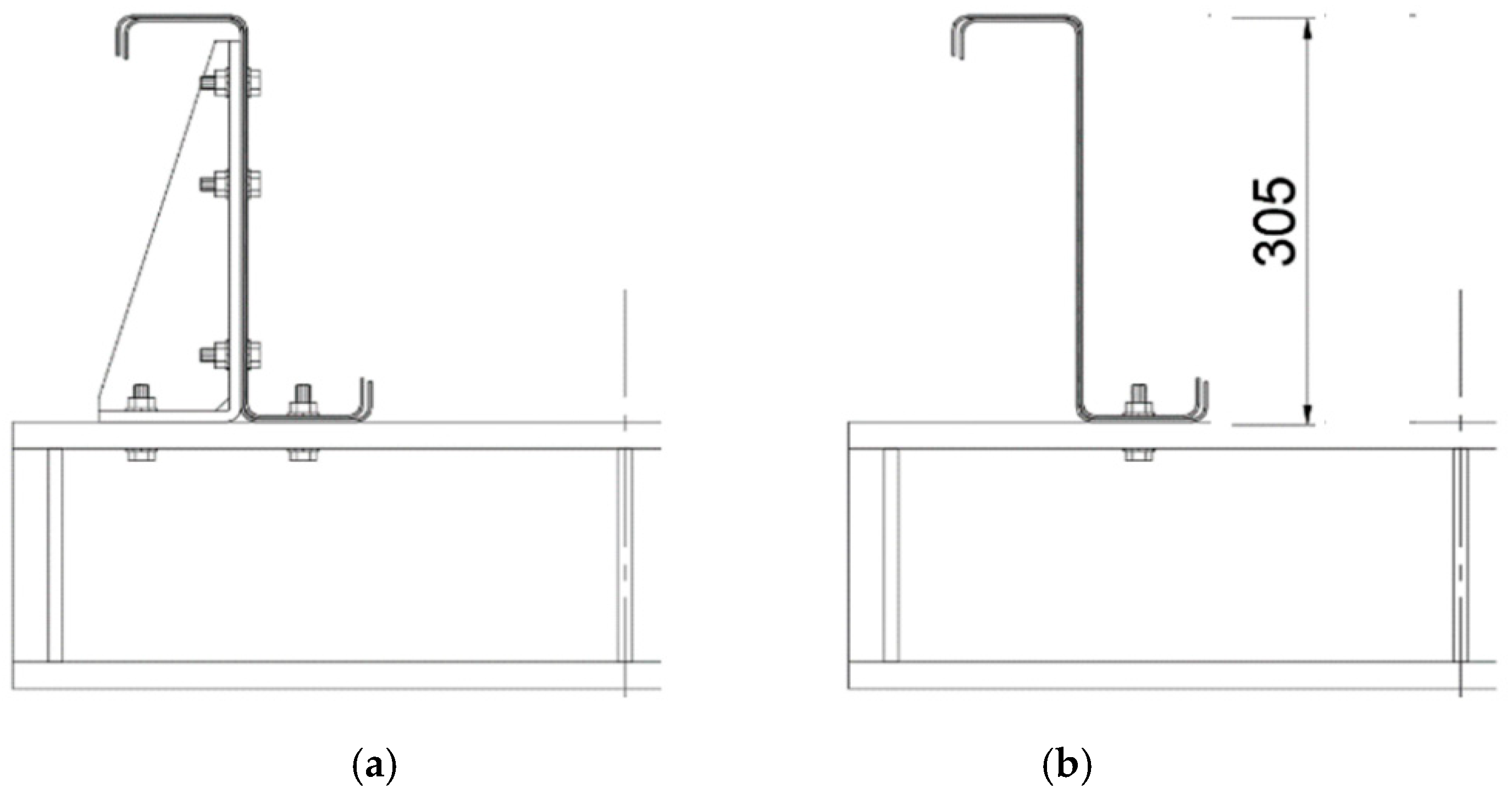
2.2. Experimental Setup and Components

The experiment was prepared in a hydraulic press machine, which can be seen in Figure 2 (nominal load tensile/pressure 400/400 kN, force sensor—GTM RF Series, accuracy 0.02 mV/V, displacement sensor—LVDT 0–300 mm, resolution ±0.25%).
The principle of the test assumed upward load, thus the distribution cross member was on the underside of the purlins and the hydraulic press machine created an apparent thrust, as the structures are, in reality, upside down. There are mostly tensile forces with a combination of bending. The test setup is shown in Figure 3, where the arrangement of the individual parts of the experiment can be seen (setup for Z300). In this experimental set-up, the flange of the beams is stabilized by crossbars located on the upper pressed flange. The red marks show the position of the extensometers and the green arrow instead of loading the press. The support span was 3.0 m. As mentioned above, two different purlins were chosen, namely Z300 and Z350, the dimensions of which are shown in Figure 3c,d. The asymmetrical Z-shaped cross section is a complication owing to the formation of transverse forces. When loading an asymmetrical profile, these transverse forces arise from torsion, as the applied load does not act in the shear centre of the asymmetrical profile. The effect of these transverse forces can be compensated with double the purlins. For this reason, the test set is symmetrical, where the transverse forces on the individual beams cancel each other out (see Figure 3b).
Within the experiment, the so-called overlap of two identical profiles was used. The use of overlap is always realized in construction in the place of supported or point stress, but here, in the experiment, the doubling of the beams is realized along the entire length of the tested beams. This overlap guaranteed that the weakest link of the tested assembly was the area of the connection and, therefore, the load-bearing capacity was reached directly in the monitored detail of the joints. The Z-profile flanges, which are due to the bending moment in the compressed part of beams, were protected from buckling by two transverse screwed Omega profiles (see Figure 3a). Another component of the test set-up was the middle distribution element, which was placed in the middle of the span and bolted to purlins. Using these distribution elements, a load applied the displacement of the press head, which acted on the canter of the distribution element, and thus also on the axis of the whole test assembly of the two beams, in the experimental setup used for connection bolts M12.
Other tested components of beam connection were reinforcement clips, which are formed by bent sheet metal with welded reinforcement. The thickness of the reinforcement plate was 8 mm and the steel grade was designed as S355. The experiments were carried out with or without a clip (see Figure 4). The reinforcement clips in Figure 5 are shown schematically for both profile heights. All bolts used in the tested assembly were of M12 strength class 4.6.

2.3. Experiment Schedule

The upward load can be considered as extreme and not very well researched with regards to TW-CRCS. The most significant factor is that there is different stress at the point of connection of the purlins. There are mostly tensile forces with a combination of bending. In contrast to gravity, there is no pressure at the abutment point of the Z-profile flange.
The tests were carried out in collaboration with Astron Buildings S.A. [21], which supplied the material. Eight large-format experimental tests were prepared on symmetrical assemblies loaded according to the above schemes. The total length of the Z profiles was 3800 mm and four Z profiles were prepared for each test. The schedule of experimental tests is given in Table 2, where the set of storage parameters is given. The aim was to analyse the influence of the reinforcement clip on the load-bearing capacity and behaviour of high profiles.
As part of the comparison of the results of the experiment to those of the normative procedure, the tension resistance of the M12-4.6 bolts and the punching shear resistance of the flange were evaluated. According to EN 1993-1-8 [22], the maximum tension resistance is determined according to the following equation:
F t , R d = k 2 f U B A S γ M 2 ,
where k2 is the factor for ordinary bolts (0.9), fUB is the maximum tensile strength of the bolt (for class 4.6, fUB = 240 MPa), AS is the tensile stress area (for bolt M12, AS = 84 mm2), and γM2 is the safety factor (1.25).
The punching shear resistance is as follows:
B p , R d = 0.6 π d m t p f u γ M 2 ,
where dm is the diameter of the bolt (for M12, dm = 12 mm), tp is the thickness of the plate (for this case, tp = 8 mm), and fu is the maximum tensile strength of the plate (for 1.89, fu = 538 MPa and, for 2.85, fu = 501 MPa).
Equations (1) and (2) were used to calculate the values, which are compared to the measured results in the next chapter.

3. Results

The confirmed assumption was that the bolts that connect the purlin flange and the reinforcing clip to the supporting structure act against the force acting on this bearing. These bolts are stressed mainly by tension and partly by praying.

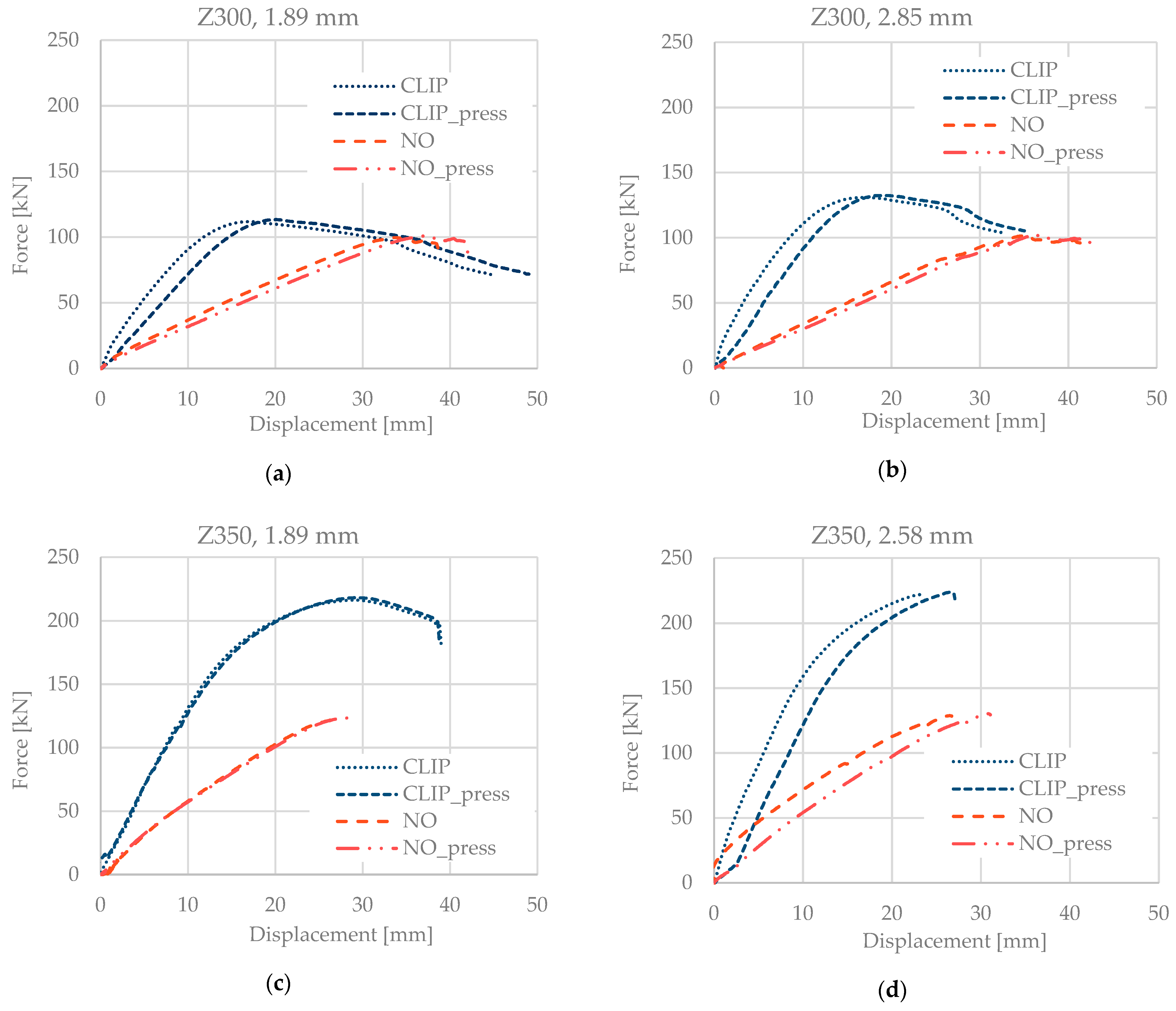
3.1. Experimental Results

The results of the experiments are presented in Figure 6. The graphs show the measured values for the whole test assembly consisting of two beams. The resulting load values for one purlin connection must thus be divided by two. It is not necessary to perform this mathematical operation for deformation results—it is a real result. The graphs show the values from the Ahloborn Almemo FWA100TR meter as well as directly from the hydraulic load press measurement system (marked as press). One graph shows a combination of one purlin’s height and one thickness, together with the clip and without the clip.
On the assembly, there is one separate sensor on the surface and one sensor directly in the head of the hydraulic press machine. t can be seen from the graph that almost all the displacement results are slightly shifted between the internal sensor and the external sensor. This is because of the overall stiffness of the experimental set-up, but importantly, the maximum forces are almost identical. The Z350 profile has higher values of maximum forces than the Z300 profile. The higher thickness increases the maximum force value relatively little. Most obviously, the assembly with a reinforcing clip creates almost double the resistance of the higher Z350 profiles. On the other hand, with Z300, the clip assembly is not as durable. In all cases, the behaviour of an assembly without a clip and with a clip is different. The clip resists displacement for longer and, in some cases, creates a descending branch when the maximum force is reached.

3.2. Failure Modes

During the experiments, it was observed how the purlin connection collapses. From the point of view of thin-walled purlins, whether or not these is some crippling is monitored. This phenomenon occurred only to a limited extent. This is the case with the connection of purlins with a reinforcing clip, where, after reaching the bearing capacity of the bolts, the edge parts of the cross section began to bulge locally in the area of the pressed flange (see Figure 7).
For all tested set-ups, it was found that the weakest component was the bolt joints. When the bearing capacity was reached, two phenomena occurred. For the thin-walled purlin flange bolts, either the head of one of the bolts was pushed (see Figure 8), or one of the bolts was broken (Figure 9). This mainly occurred with the bolts connecting the reinforcing clip and the main supporting structure. The reason was the combination of the relatively rigid clip and the flexible flanges of the thin-walled purlins.

3.3. Comparison with the Normative Capacity

Maximum force values were obtained from the measured force–displacement graphs. These results are shown in Table 3. As mentioned above, the results of the measured bearing capacity in the bolts were compared to the normative values according to Formulas (1) and (2).
It can be seen that, for all cases, the measured value of force is greater than the value for tension resistance in the bolt, according to the equation. On the contrary, the values of the punching shear resistance of the normative equation are higher in all cases wherein a reinforcing clip was not used and in one case wherein it was used (for Z300, 1.89 mm). In other cases, the values from the experimental measurements are larger, which proves the importance of the reinforcement clip. These findings correspond to the failure modes shown in Figure 7, Figure 8 and Figure 9.

4. Conclusions

This paper presented experimental testing of the connection of TW-CRCS Z-purlins and roof structure frames. Purlins Z300 and Z350 and two cross sections with thicknesses of 1.89 and 2.85 were selected. These high profiles are beginning to be used to design and build large production halls. The experimental set-up simulated the upward load (for example, wind suction). The following conclusions were obtained from the experimental measurements:
  • Z350 profiles achieved a significantly higher load-bearing capacity than Z300 profiles, especially in the case of connecting a reinforcing clip.
  • For Z300 profiles, the maximum force values with and without a clip were quite similar for different material thicknesses, although the displacement curve was different.
  • It was confirmed that the weakest component was the screw connections and that the redistribution of stress in the clip could cause the screw to break.
  • The results show that the clip increases the stability of the connection.
  • The load-bearing capacity values correspond to the results of the analytical solution from standards. In the case of tension, the resistance of the screw is higher, but in the case of extrusion, the punching resistance is slightly lower. This applies to samples without a clip.
The results can contribute to expanding knowledge on TW-CRCS purlins. The basic recommendation points out the fact that, to achieve the normative load-bearing values, the connection should be made using a reinforcing clip. Further combinations of high purlin material thickness profiles will demonstrate whether these conclusions are acceptable.

Author Contributions

Conceptualization, M.R., and P.P.; methodology, P.L., and P.P.; software, P.P., and P.L.; validation, O.S., P.P., and M.R.; formal analysis, P.P., and O.S.; investigation, O.S.; resources, P.P.; data curation, P.L.; writing—original draft preparation, P.L., and P.P.; writing—review and editing, O.S., P.P., and M.R.; visualization, P.L.; supervision, M.R.; project administration, M.R.; funding acquisition, P.P. All authors have read and agreed to the published version of the manuscript.

Funding

Financial support from VŠB-Technical University of Ostrava by means of the Czech Ministry of Education, Youth, and Sports through the institutional support for conceptual development of science, research, and innovations for the year 2021 is gratefully acknowledged.

Conflicts of Interest

The authors declare no conflict of interest.

References

  1. Shifferaw, Y.; Woldeyes, K.; Bitsuamlak, G. Stability and Strength Behavior of Thin-Walled Roof-Panel-Purlin System under Wind Loading. In Proceedings of the Annual Stability Conference Structural Stability Research Council 2017, San Antonio, TX, USA, 21–24 March 2017. [Google Scholar]
  2. Pham, C.H.; Davis, A.F.; Emmett, B.R. Numerical Investigation of Cold-Formed Lapped Z Purlins under Combined Bending and Shear. J. Constr. Steel Res. 2014, 95, 116–125. [Google Scholar] [CrossRef]
  3. Seek, M.W.; Avci, O.; McLaughlin, D. Effective Standoff in Standing Seam Roof Systems. J. Constr. Steel Res. 2021, 180, 106590. [Google Scholar] [CrossRef]
  4. Lambiase, F.; Di Ilio, A. An Experimental Study on Clinched Joints Realized with Different Dies. Thin-Walled Struct. 2014, 85, 71–80. [Google Scholar] [CrossRef]
  5. Zhao, C.; Yang, J.; Wang, F.; Chan, A.H.C. Rotational Stiffness of Cold-Formed Steel Roof Purlin–Sheeting Connections. Eng. Struct. 2014, 59, 284–297. [Google Scholar] [CrossRef] [Green Version]
  6. Eurocode 3 Part 1–1: General Rules—General Rules and Rules for Buildings; European Committee for Standardization (CEN): Brussels, Belgium, 2006; ISBN 5947185067.
  7. Eurocode 3 Part 1–3: General Rules—Supplementary Rules for Cold Formed Thin Gauge Members and Sheeting; European Committee for Standardization (CEN): Brussels, Belgium, 2006; ISBN 5947185067.
  8. Vraný, T.; Belica, A.; Szabó, G. Cold-Formed Double C Beam-Column with Discrete Elastic Supports at Compression Flange. In Proceedings of the International Colloquium on Stability and Ductility of Steel Structures, Lisbon, Portugal, 6–8 September 2006; pp. 673–680. [Google Scholar]
  9. Silva, J.M.M.; Malite, M. Longitudinally Stiffened Web Purlins under Shear and Bending Moment. Thin-Walled Struct. 2020, 148, 106616. [Google Scholar] [CrossRef]
  10. Sivapathasundaram, M.; Mahendran, M. Experimental Studies of Thin-Walled Steel Roof Battens Subject to Pull-through Failures. Eng. Struct. 2016, 113, 388–406. [Google Scholar] [CrossRef]
  11. Fish, R.A.; Lee, M.; Rasmussen, K.J.R. Torosional buckling experimentals on wide-flange thin-walled z-section columns. In Advances in Steel Structures (ICASS ’02); Elsevier: Amsterdam, The Netherlands, 2002; pp. 357–364. [Google Scholar]
  12. Flodr, J.; Krejsa, M.; Mikolasek, D.; Brozovsky, J.; Parenica, P. Numerical Modeling of a Thin-Walled Profile with Respect to the Redistribution of Bending Moments. Civ.-Comp Proc. 2015, 108, 1–15. [Google Scholar] [CrossRef]
  13. BW Industries. Available online: https://www.bw-industries.co.uk/ (accessed on 10 October 2020).
  14. Parenica, P.; Sucharda, O.; Lehner, P. Parametric Study of High Thin-Walled Z-Purlins Structural Connection with Additional Clip. ARPN J. Eng. Appl. Sci. 2018, 13, 1615–1623. [Google Scholar]
  15. Pařenica, P.; Rosmanit, M.; Flodr, J. Numerical Modelling of Thin-Walled Purlins Connection to the Supporting Structure. Procedia Eng. 2017, 190, 186–192. [Google Scholar] [CrossRef]
  16. Kordan, H.A. Distortional Buckling of Cold-Formed Steel Members in Bending. Int. J. Environ. Stud. 2006, 5, 221. [Google Scholar] [CrossRef]
  17. Carbas, S.; Saka, M.P. Optimum Design of Cold-Formed Thin-Walled Sections Subjected to Axial and Bi-Axial Bending Using Artificial Bee Colony Algorithm. Res. Eng. Struct. Mater. 2016, 2, 29–37. [Google Scholar] [CrossRef]
  18. Gutierrez, R.; Loureiro, A.; Reinosa, J.M.; Lopez, M. Numerical Study of Purlin Joints with Sleeve Connections. Thin-Walled Struct. 2015, 94, 214–224. [Google Scholar] [CrossRef]
  19. Yang, N.; Bai, F. Damage Analysis and Evaluation of Light Steel Structures Exposed to Wind Hazards. Appl. Sci. 2017, 7, 239. [Google Scholar] [CrossRef]
  20. Metallic Materials—Tensile Testing—Part 1: Method of Test at Room Temperature; EN 10002-1:2001/ISO 6892-1; International Organization for Standardization: Geneva, Switzerland, 2009.
  21. ASTRON-R&D Calculated Local Resistances of the Internal Supports for the Overlaped Z Purlins with or without Clip. Available online: https://www.astron.nl/research-and-innovation, (accessed on 10 October 2020).
  22. Eurocode 3: Design of Steel Structures—Part 1–8: Design of Joints; EN 1993-1-8; European Committee for Standardization: Brussels, Belgium, 2005.
Figure 1. (a) Diagram of purlins connected on the main roof structure and (b) 3D model of the connection.
Buildings 11 00512 g001
Figure 2. Load experiment of Z350 purlins at a span of 3.0 m.
Buildings 11 00512 g002
Figure 3. Scheme of the experimental set-up: (a) side view, (b) cross section for purlins Z300, and dimensions of purlins (c) Z300 and (d) Z350—all in mm.
Buildings 11 00512 g003
Figure 4. Support region cross-section details (a) with a clip and (b) without a clip.
Buildings 11 00512 g004
Figure 5. Dimensions of the reinforcement clip (a) for Z300 and (b) for Z350 (mm).
Buildings 11 00512 g005
Figure 6. Force-displacement graphs for (a) Z300, 1.89 mm; (b) Z300, 2.85 mm; (c) Z350, 1.89 mm; and (d) Z350, 2.85 mm.
Buildings 11 00512 g006
Figure 7. Photos of local buckling of the pressed part of the cross section with a clip.
Buildings 11 00512 g007
Figure 8. Photographs of pushed bolt heads with flanges Z profiles, 1.89 mm.
Buildings 11 00512 g008
Figure 9. Photograph of the broken bolts.
Buildings 11 00512 g009
Table 1. Parameters of cold-rolled steel of class S350 GD from tensile tests.
ThicknessParameterMin.Max.MeanSTD.
(mm) (MPa)(MPa)(MPa)
1.89fy444.76480.70457.105.52
fu517.95606.46538.0015.11
2.85fy398.72438.48425.2010.26
fu484.54514.83501.806.63
Table 2. Experiment schedule and parameters.
Purlins’ Height (mm)Thickness (mm)ClipSupport Width (mm)
3001.89No clip200
3001.89CLIP200
3002.85No clip200
3002.85CLIP200
3501.89No clip200
3501.89CLIP200
3502.85No clip200
3502.85CLIP200
Table 3. Results from experimental tests and comparison to normative values.
SampleMaximal Force F (kN)Force in One Bolt Fi * (kN)Tension Resistance Ft.Rd (kN)Punching Shear Resistance
Bp.Rd (kN)
Compare
F i F t . R d F i B p . R d
300 1.89 No clip101.025.2524.331.4104%80%
300 1.89 CLIP113.328.33117%90%
300 2.85 No clip123.930.9844.1127%70%
300 2.85 CLIP218.254.55224%124%
350 1.89 No clip102.725.6831.4106%82%
350 1.89 CLIP132.533.13136%105%
350 2.85 No clip130.332.5844.1134%74%
350 2.85 CLIP224.056.00115%127%
* The load distribution to four bolts for the No Clip set-up and eight bolts for the CLIP set-up is assumed.
Publisher’s Note: MDPI stays neutral with regard to jurisdictional claims in published maps and institutional affiliations.

