Article

Simulation Study of a Novel Cylindrical Micro-Electrostatic Particulate Air Filter with High Filtration Efficiency and Low Resistance

Department of Environmental Science and Engineering, Tianjin University, Tianjin 300350, China
*
Author to whom correspondence should be addressed.
Buildings 2021, 11(10), 465; https://doi.org/10.3390/buildings11100465
Submission received: 27 August 2021 / Revised: 29 September 2021 / Accepted: 8 October 2021 / Published: 11 October 2021
(This article belongs to the Special Issue Advances in the Indoor Environments and Respiratory Health)

Abstract

:
The purification of indoor pathogenic microorganisms has become a topic of concern. The use of nonwoven media air filters causes high resistance, and the problem of noise limited their application under high air volume. Thus, we propose a micro-electrostatic filter, which has improved performance compared to an electrostatic filter, with a new type of cylindrical structure to tackle indoor pathogenic microbial aerosol pollution. Through simulation, it is found that the filtration performance of a cylindrical structure is better than that of a plate structure under all simulation conditions. For particles larger than 1 μm, the shortest theoretical length of the dust collecting plate required for the cylindrical structure is 34% shorter than that for the plate structure. For 0.1 μm particles, the filtration efficiency of the cylindrical structure is nearly 20~30% (the maximum value is 29.76%) higher than that of the plate structure, while the air velocity is 1.5 m/s~2.5 m/s. The resistance of the cylindrical micro-electrostatic filter is only half of that of the combined plate type micro-electrostatic filter, indicating that the cartridge structure has enormous energy-saving potential. The introduction of the quality factor further proves that the integrated filtration performance of the cartridge micro-electrostatic filter is better. The application of cylindrical micro-electrostatic filters in HVAC systems can help improve indoor air quality and reduce health risks.

1. Introduction

In recent years, frequent outbreaks of airborne infectious diseases have become a cloud on the horizon on human health, including the outbreak of severe acute respiratory syndrome (SARS) in 2003, H1N1 influenza in 2009, and Middle East respiratory syndrome in 2012. In particular, the COVID-19 pandemic, which began to rage through the world in December 2019, has delivered a devastating blow to society [1,2]. In addition to particles, people have begun to focus on pathogenic microorganisms in indoor air environments. At present, fan coils and combined air conditioning systems, which are considered some of the most important sources of indoor pathogenic microbial pollution [3,4], are equipped with only medium-efficiency filters [5,6] at levels F7, F8, and F9 [7], which have a low filtration efficiency for pathogenic microbial aerosols of only approximately 70% [8]. Improving indoor ventilation and the filtration efficiency for pathogenic microorganisms will significantly reduce the risk of indoor pathogenic microorganism infection [9]. However, in the existing heating, ventilation, and air conditioning (HVAC) systems, increasing the filtering air volume will result in a substantial increase in resistance [10,11]. Additionally, to use high-efficiency media filters for air purification of residential and commercial buildings as a way to achieve high filtration efficiency will lead to unacceptably high resistance and high energy consumption [12,13]. Therefore, it is essential to develop a filter that has low resistance under high air volume and has a high filtration efficiency for pathogenic microorganisms at the same time.
Compared with medium-efficiency media filters widely used in existing air conditioning systems, electrostatic filters have similar filtration efficiency and lower resistance [14,15,16,17,18]. Another reason to consider using electrostatic filters in HVAC systems is that electrostatic filters can disinfect in addition to physically trapping pollutants. According to early experimental work, an electrostatic filter will produce many ions during operation. Pathogenic bio-aerosols in the air are effectively disinfected upon exposure to ions [19,20,21,22,23,24,25,26].
Electrostatic filters were first used for industrial dust removal and are now widely used in various industries, including commercial kitchens, air purification, and other fields [14,15,27,28]. The filtration efficiency of an electrostatic filter is mainly determined by the discharge voltage and the voltage of the dust-collection plate [29]. Based on this, researchers have made structural design changes to the electrostatic filter, for example, from a single-zone electrostatic filter to a double-zone electrostatic filter [30]. The flat-plate double-zone electrostatic filter separates the discharge area from the dust-collection area. The electric field intensity near the dust-collecting electrode surface usually increases from less than 5 × 10⁵ V/m to 106 V/m [31]. However, most of the dust-collection plates of traditional electrostatic filters are metal plates, and their surface is often not guaranteed to be sufficiently flat. As a result, the local electric field intensity around a spike in the surface will be much higher than the average field intensity [30]. Moreover, there is a risk of introducing byproducts such as ozone if the electrostatic filter is directly introduced into an indoor environment where people are present [32,33,34].
To enhance the field strength between the electrode plates and reduce ozone generation, an intense field dielectric (IFD), also called a micro-electrostatic filter, was proposed. It encapsulates the metal electrode in the dielectric material to achieve high efficiency, low resistance, and low ozone emission [35,36,37]. In the research on the plate-type micro-electrostatic filter, the researchers have proved that the resistance of the plate-type micro-electrostatic filters is only 14 Pa at 1.0 m/s, and the initial PM2.5 filtration efficiency can also reach 99.8%. However, after 50 days of operation, the PM2.5 filtration efficiency of a plate-type micro-electrostatic filter drops to 50% [20]. This study also means that although the efficiency of a plate-type micro-electrostatic filter has reached the level of a medium-efficiency filter, its filter performance is challenging to regulate after it contains dust [14,20,38]. Therefore, improving the dust-holding capacity (DHC) of the micro-electrostatic filter is the key to its application in HVAC systems.
Additionally, increasing indoor ventilation can effectively reduce indoor pathogenic microorganisms and viruses [39]. To increase the air volume of the filter in an existing HVAC system, we combined four plate-type micro-electrostatic filters together, and the airflow direction is shown in Figure 1a. Similar to this structure, the cylindrical structure is used for a fiber filter to reduce the trade-off between resistance and efficiency. A cylindrical structure has a larger filtration area and higher filtration efficiency at the same resistance [40,41,42], often used in automobile filters and aviation filters [43,44]. Based on the above analysis, we have designed a cylindrical micro-electrostatic filter. It is expected to operate with low resistance under a high air volume while ensuring high filtration efficiency. The structure and airflow direction are shown in Figure 1b.
This research compares the filtration performance of the novel cartridge-type micro-electrostatic filter (Figure 1b) with the combined plate-type micro-electrostatic filter (Figure 1a). It is assumed that both the filtration area at the inlet and the length of the electric field channel are the same. Simultaneously, the mainstream characteristics of the two types of micro-electrostatic filters are similar. Therefore, the filtration efficiency is determined by the movement of particles in the electric field channel, which are shown at the rightmost side of Figure 1. Therefore, by simulating the movement of particles in the electric field channel and the filtration performance, a comparison of the filtration performance of the cartridge micro-electrostatic filter and the combined plate-type micro-electrostatic filter can be obtained. From a qualitative perspective, compared with the combined plate-type micro-electrostatic filter as shown in Figure 1a, the cross-sectional area of the electric field channel for the cylindrical structure gradually increases along the airflow direction. Furthermore, this increase helps reduce the movement velocity of particles, thereby bringing higher filtration efficiency and lower pressure drop.
During indoor transmission, viruses, bacteria, and other pathogenic microorganisms are often not transmitted as a single body but are mostly attached to dust in the air or condensed into larger particles [45,46]. According to previous research [47], bacteria are usually mixed with other airborne microorganisms, resulting in a diameter of 1.0 μm~5.0 μm in air. Martin Möritz et al. studied the pathogenic microbial removal performance of air filters in HVAC systems [8]. Their results showed that the pathogenic microbes that grow and reproduce on the filter and reenter the air have a particle size of 1.1 μm. Additionally, Li et al. compared the actual removal efficiency of pathogenic microorganisms and particulate matter through experiments and found that the removal efficiencies were basically the same after 60 s [48]. When conducting simulation studies on pathogenic microbial purification, researchers often simplify the simulation to particles larger than 1 μm [49,50]. Although microorganisms are mainly considered particles larger than 1 μm, it is still necessary to evaluate the filtration performance of single-sized particles of 0.1 μm~1 μm [51]. Therefore, we use particles larger than 1 μm and 0.1 μm~1 μm to simulate the capture process of microbial aerosols.
In this research, we take pathogenic microorganisms (simplified as particles) as target pollutants. By simulating the movement of particles in an electric field channel (hereinafter collectively referred to as single channel simulation, Section 2), we compared the cylindrical structure and the combined plate structure under different working conditions (Section 3.1). Additionally, we used the “shortest trapping length’’ (STL) required for particles larger than 1 μm, minimum filtration efficiency, airflow resistance, and quality factor to compare the cartridge micro-electrostatic filter and combined plate micro-electrostatic quantitatively (Section 3.2 and Section 3.3). The applicable conditions of the cylindrical micro-electrostatic filter and aspects that can be further studied are discussed in Section 3.4. Based on the simulation research, technical advantages and valuable conclusions of the cylindrical micro-electrostatic filter are given quantitatively (Section 4).

2. Materials and Methods

A micro-electrostatic filter is composed of multiple electric field channels, and the movement of particles in an electric field channel determines the performance of the filter. A single channel model is often used for simplified calculation [20] to simulate the performance of the electrostatic filter and was adopted in this research. We first used the methods commonly used in the literature [20,52] to simulate the flow field and the electrostatic field, and then establish the particle motion and charging model in the electric field channel. The accuracy of the model was verified by using the data and results of Xiong. et al. [20]. The schematic diagram of the research method used is shown in Figure 2.

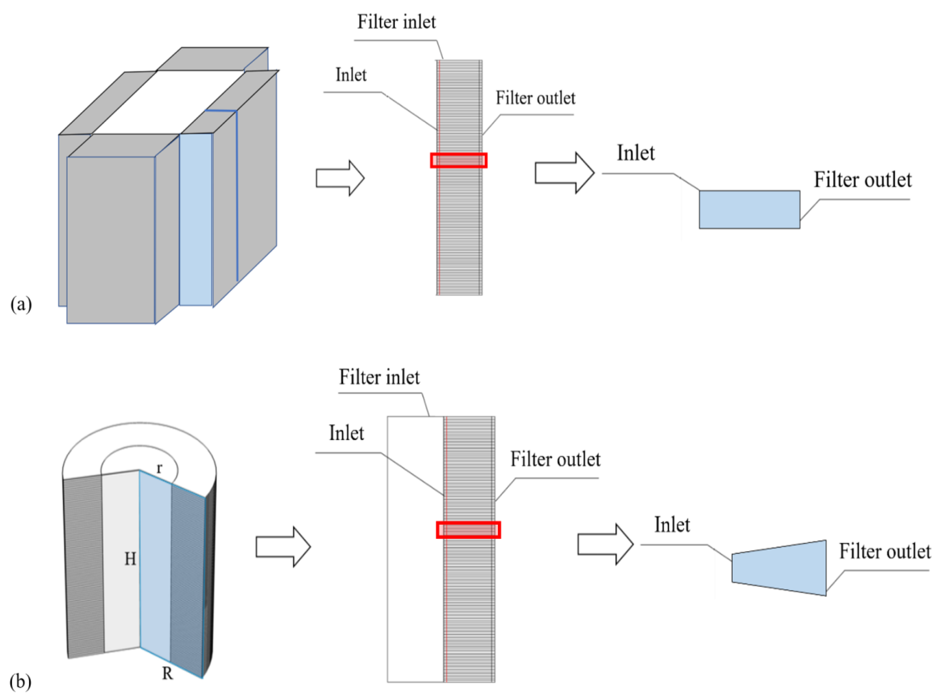
2.1. Flow Field and Electric Field Model

The single channel model is a multi-physics system including flow field and electric field. According to previous research [20,52], the standard k-ε model is suitable for the flow field calculation of the single channel model. The governing equations can be expressed as:
ρ t + · ( ρ u ) = 0 ,
ρ u t + · ( ρ u u τ ) = f ,
where ρ is the density of the fluid (kg/m3), t is time (s), u is the velocity field of the fluid (m/s), τ is the stress tensor (Pa), and f is the fluid volume vector (N/m3).
For the single channel model, the ion concentration in the airflow is very low and insufficient to change the space charge density. Therefore, we use the Poisson equation to simulate the electric field:
E = φ ,
( ε 0 ε r E ) = ρ e ,
where E is the electric field strength (V/m), φ is the electric potential between the dust-collection plates (V), ε 0 is the absolute dielectric constant of a vacuum (C/(m·V)), ε r is the relative permittivity, and ρ e is the volumetric space charge density (C/m3).

2.2. Particle Charge Model and Force Analysis

Charging is instantaneous under a certain electric field strength [53,54,55]. Therefore, when simulating the charging of particulate matter, we adopted the following assumption commonly used in the literature: each particulate passes through the needle tip discharge device to reach a saturated state of charge [16]. The charging principle of particles of different sizes varies. Particles larger than 0.5 μm collide with other ions or charged particles to obtain additional ions for charging, which is called field charging. Particles with a particle size between 0.3 μm and 0.5 μm are not only subjected to diffusion charging due to thermal motion (referred to as Brownian motion), but also to field charging. Cochet [56] comprehensively considered field charging and diffusion charging and gave a comprehensive model. For a particle of a given size, the particle charge can be expressed as saturated field charge or syndicate charge, as shown in Equations (5) and (6).
d p > 0.5   μ m ,                               q s = 3 ε ε + 2   π ε 0 E d p 2 ,
0.3     μ m   d p 0.5   μ m ,                 q p = π ε 0 E d p 2 [ ( ε 1 ε + 2 ) ( 2 1 + 2 λ d p ) + ( 1 + 2 λ d p ) 2 ] ,
where   q s is saturated field charge (C), q p is syndicated charge (C), ε 0 = 8.85 × 10 12   C / ( N · m 2 ) , ε is the relative permittivity of particles, and λ is the mean free-path of gaseous molecules (m).
The force of particles in the electric field determines the form of the particle motion. The motion trajectory equation of the particulate matter can be expressed by the classic Newtonian equations. Therefore, the differential equation of particle movement in the electric field is:
m d u d t = q E y + 3 π μ d p ( u v ) C u ,
where m is the mass of a single particle (kg), v is the velocity field of the particles, E y is the local electric field strength of the dust-collecting pole (V/m), μ is the air dynamic viscosity (N·s/m2), C u is the Cunningham slip correction factor, and the calculation equation of C u is as follows [57]:
C u = 1 + 2 λ d p [ 1.257 + 0.4 e x p ( 0.55 d p λ ) ] ,
The first term on the right side of Equation (7) represents the electric field force received by the particle, and the second term represents the drag force between the particle and the fluid.

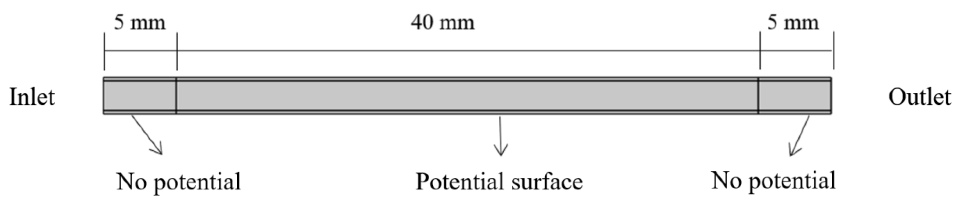
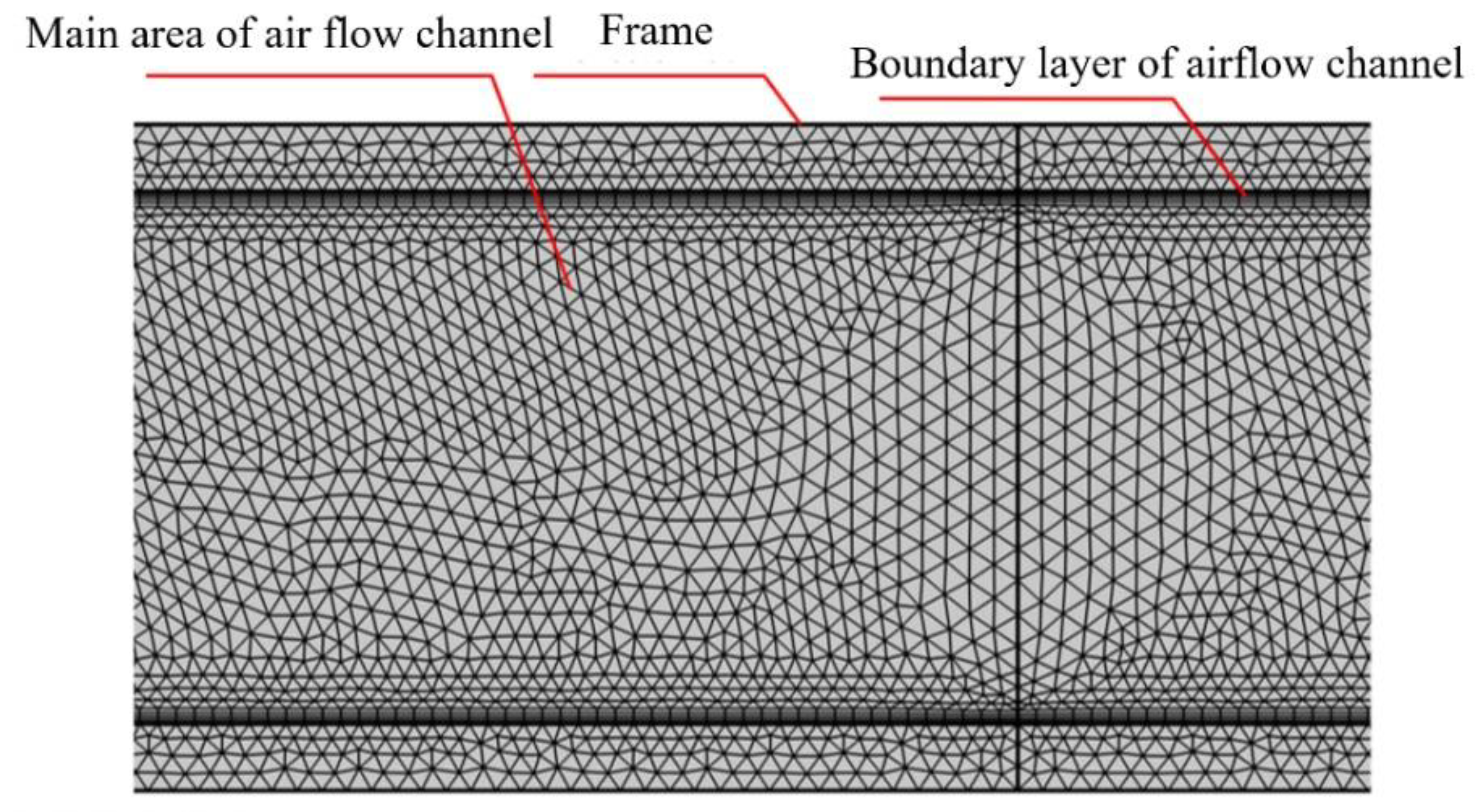
2.3. Boundary Conditions and Meshing

As shown in Figure 3, the physical model of the single channel model is divided into three parts: inlet, electric field channel, and outlet. The central section of the electric field channel, with a length of 40 mm, is used for display, and the electric potential was applied to the outer surface of the outer frame. The inlet and outlet dimensions of the combined plate-type electric field channel are 2.5 mm × 5.0 mm. The inlet and outlet dimensions of the cylinder electric field channel are 2.5 mm × 5.0 mm and 2.5 mm × 7.5 mm. Velocity inlet and pressure outlet boundaries are used for the flow field simulation, and the walls of the electric field channel adopt nonslip boundary conditions. The outlet pressure is set to 0 and the inlet air velocity is set to 1.0 m/s, 1.5 m/s, 2.0 m/s, and 2.5 m/s.
The inlet and outlet are set to “no potential vertical difference” in the electric field simulation. One pole of the electric field channel is grounded, and the other is a high-voltage pole. The voltage values are 6.0 kV, 7.0 kV, 8.0 kV, 9.0 kV, and 10.0 kV. The particles are uniformly released from the inlet at an injection rate of 10,000 particles/s. The constants used in the modeling process are shown in Table 1.
In the process of meshing, as shown in Figure 3, the geometric model is divided into the following two parts: the air-flow channel and the outer frame. There are 5 mm nonelectrode-covered parts at both the inlet and outlet. Therefore, only the middle 40 mm will have an applied electric potential, and the electric potential will be applied to the outer surface of the outer frame. The inlet and outlet dimensions of the combined plate-type electric field channel are 2.5 mm × 5.0 mm. The inlet and outlet dimensions of the cylinder electric field channel are 2.5 mm × 5.0 mm and 2.5 mm × 7.5 mm.
For a single channel, the flow field and the particle field exist only inside the air channel, and there is an electric field in only the outer frame. Therefore, the grid is divided separately into the air channel and the outer frame. Since the electric field calculation is relatively simple, the grid inside the frame is a triangular grid, which is relatively sparse and does not require a boundary layer. The internal grid of the airflow channel is composed of rectangular and triangular grids, and rectangular grids mainly exist in the boundary layer. The overall model has 50,136 domain units, and a partial grid diagram is shown in Figure 4. According to the existing research [20], the grid size we use meets the requirements of the simulation and can accurately simulate the flow field.

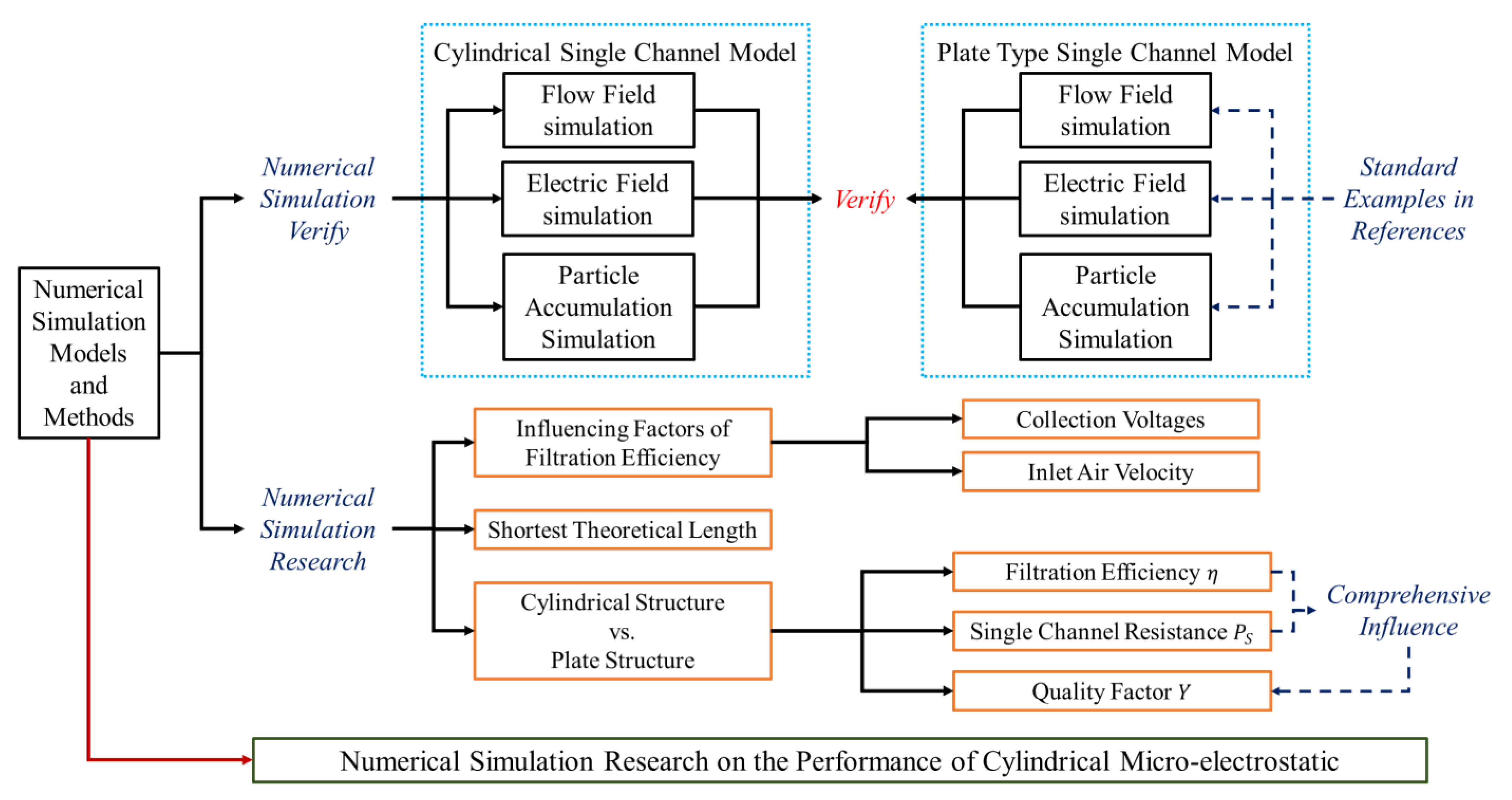
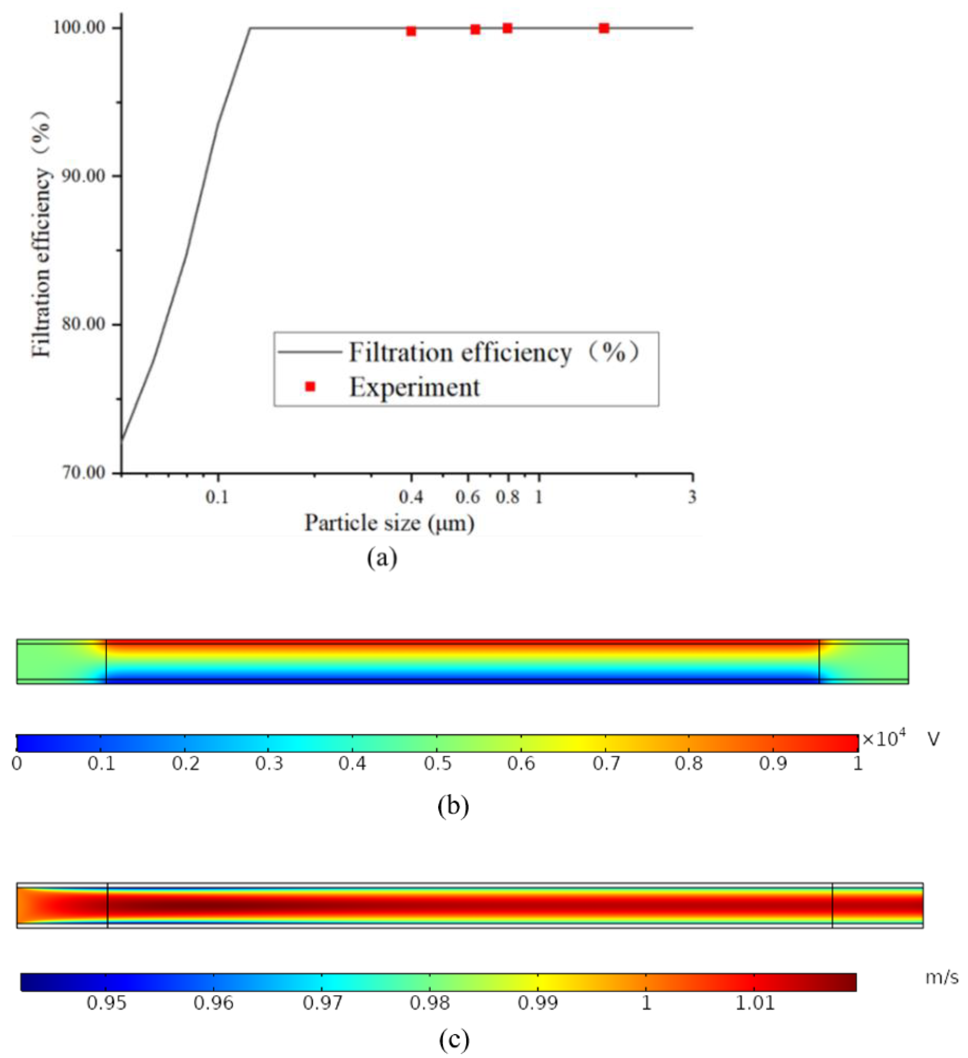
2.4. Simulation Verification

Xiong et al. [20] have conducted simulation and experimental research on the plate-type micro-electrostatic filters, and it was used to verify the accuracy of our simulation model. As shown in Table 2, a single channel simulation on the plate-type micro-electrostatic filter was done. The parameters or settings not listed in Table 2 are the same as described above. As shown in Table 3, the experimental data used for verification are the measured fractional efficiency by particle size at 1.0 m/s.
Taking the working condition with an inlet air velocity of 1.0 m/s as an example, we simulated the fractional efficiency by particle size in a single channel, and the verification result of the simulation model is shown in Figure 5a. The black line in the figure is the fractional efficiency by particle size obtained by our simulation model, and the red square is the experimental value shown in Table 3. It can be seen from Figure 5a that the results of the simulation are consistent with the experimental results. In addition, we also simulated the electric field and velocity field of the single channel, and the results obtained are shown in Figure 5b,c. The simulation results of the electric field and velocity field are also consistent with the literature. Therefore, our simulation method and the model we used are feasible.

3. Results and Discussion

3.1. Analysis of Influencing Factors of Filtration Efficiency

Because the effects of secondary mixing and shedding of particles can be ignored, it is assumed that the particles were wholly captured when vertically displaced on the dust-collection plate. According to the force analysis of particles in the electric field channel, as shown in Equation (7), the electric field strength between the dust collecting plates (collection voltage) and the inlet air velocity will affect the movement of particles in the electric field channel, which will then affect the filtration efficiency of the micro-electrostatic filter. Therefore, we have studied the influence of the collection voltage and the inlet air velocity on particles’ movements in the electric field channel simulation.

3.1.1. Collection Voltages

Figure 6 shows the influence of the collection voltage on the trapping of particulate matter in the electric channel of the cylindrical and the combined plate-type micro-electrostatic filter. When the discharge electrode voltage and air volume were constant, particles more prominent in size were easier to trap. When the dust-collection plate was long enough, the capture efficiency of the two structures for the usual microbial particle size (>1 μm) was 100%. However, for the single size (0.1 μm~1.0 μm), the filtration efficiency of the cylindrical structure is higher. When the air volume was constant, the lateral displacement of all particles increased as the voltage decreased. Additionally, the displacement distance of the particles in the cylindrical channel was significantly smaller than that in the plate channel, and this was more obvious at low voltages.
The filtration performance of the combined plate-type and cylindrical micro-electrostatic filters after holding dust can also be analyzed from Figure 6. As the dust-collection plate captured the particulate matter, the voltage between the dust-collection plates was continuously attenuated, and the average electric field intensity decreased, resulting in a decrease in the filtration efficiency. Therefore, if the working condition with the dust collecting plate voltage of 10.0 kV is regarded as the initial working condition with the micro-electrostatic filter, then the plate voltage of 6.0 kV can be regarded as the working condition after holding dust. According to reference [20], the number of working days corresponding to the voltage attenuation of the dust collecting plate to 60% of the initial voltage is 24 days. Comparing these two working conditions of the cylindrical micro-electrostatic filter and the combined plate-type micro-electrostatic filter, we can conclude that the cylindrical micro-electrostatic filter maintained high filtration efficiency during long-term operation.

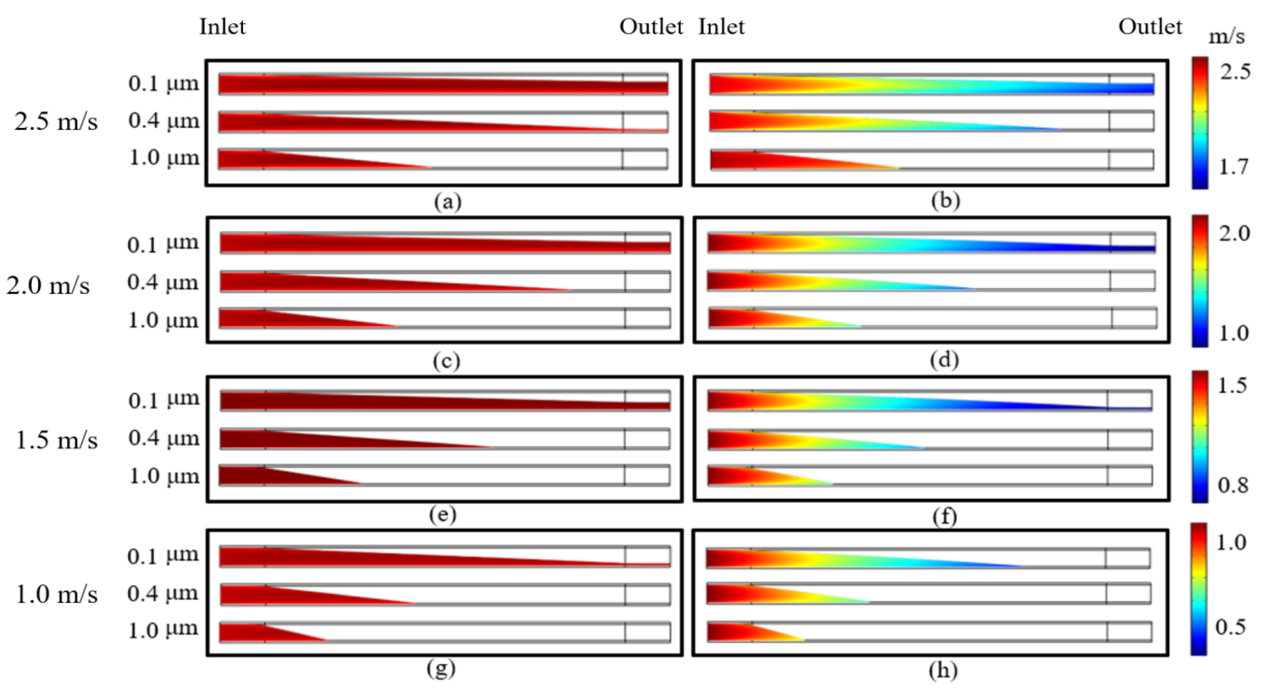
3.1.2. Inlet Air Velocity

The particle capture results of the cylindrical and plate single channel models at different inlet velocities are shown in Figure 7. As the filter efficiency for large particles was 100%, the capture of 3 μm particles is not shown here. For the single-sized particles (0.1 μm~1 μm), during long-term use under the operating conditions that we were concerned about, the filtration efficiency of 0.1 μm particles cannot reach 100% from the plate structure when the dust-collection voltage was 6.0 kV, and the air velocity was 1.0 m/s~2.5 m/s. However, for the cylindrical micro-electrostatic filter, the 100% capture efficiency for 0.1 μm particles can be ensured at 1.0 m/s. Therefore, the risk of indoor pathogenic microorganisms and viruses infecting occupation can be significantly reduced if the cylindrical filter is used in an indoor HVAC system.

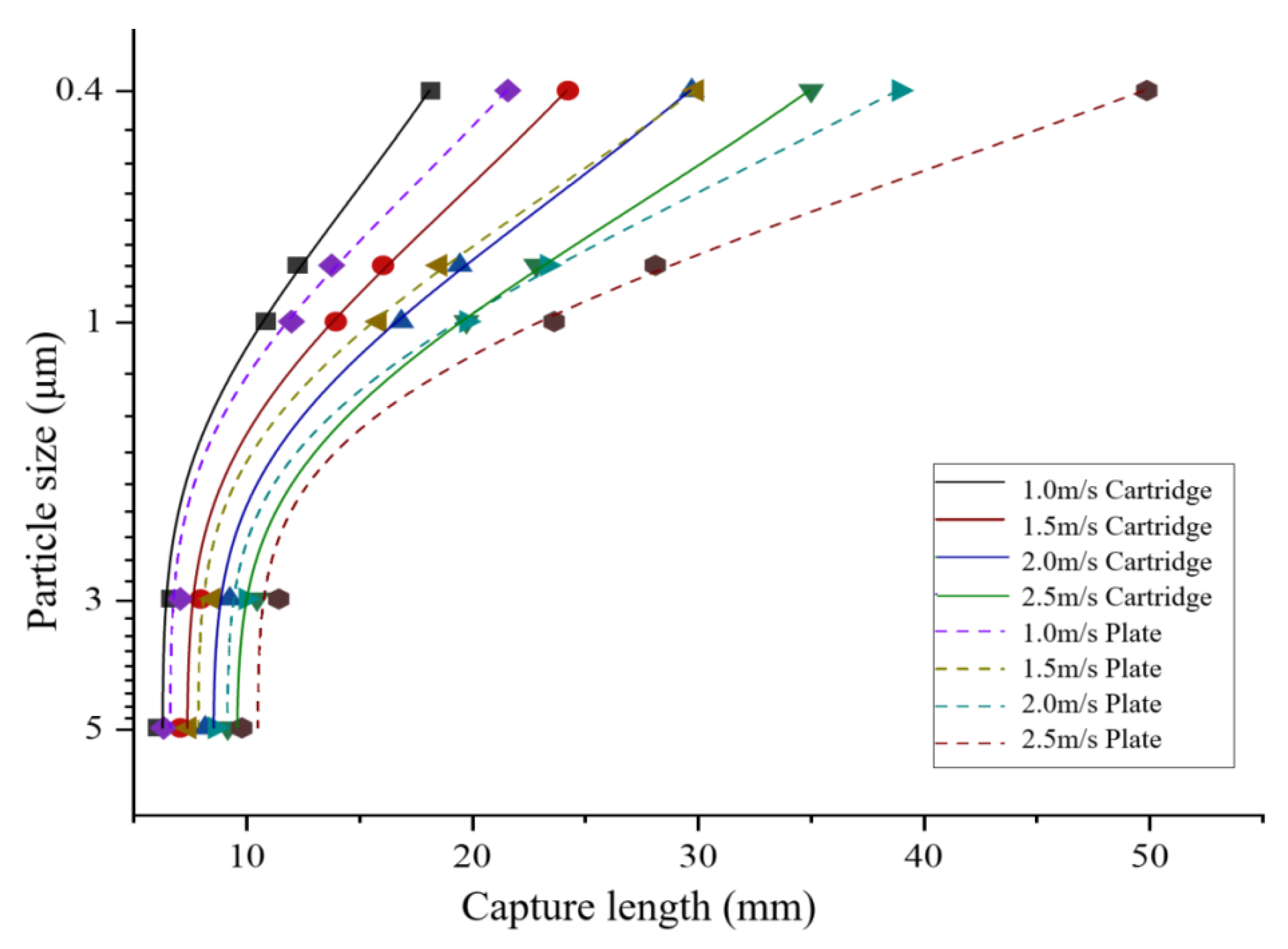
3.2. Shortest Trapping Length (STL)

We propose the “shortest trapping length (STL)” to reflect the capture efficiency of the micro-electrostatic filter on particles of a specific size. The STL means the length of the dust collecting plate under which the filtration efficiency of a specific size of particles in the electric field channel is precisely 100%. It reflects the filtration efficiency and can also be used for the structural optimization design of the micro-electrostatic filter.
Figure 8 shows the theoretical STL required by the cartridge and combined plate-type filters to trap different sizes of particles at various inlet air velocities. Taking particles larger than 1 μm as the criterion, at 2.5 m/s, the required theoretical STL was 17 mm for the cylindrical micro-electrostatic filter and approximately 25 mm for the plate structure. It can be obtained that the STL required by the cylindrical structure is 34% shorter than that of the combined plate structure. This result means that under the same inlet air velocity, the cylindrical micro-electrostatic filter needs to occupy a smaller volume than the combined plate-type micro-electrostatic filter to achieve the same filtration efficiency. It also makes the cylindrical micro-electrostatic filter more space-saving when used in an HVAC system.

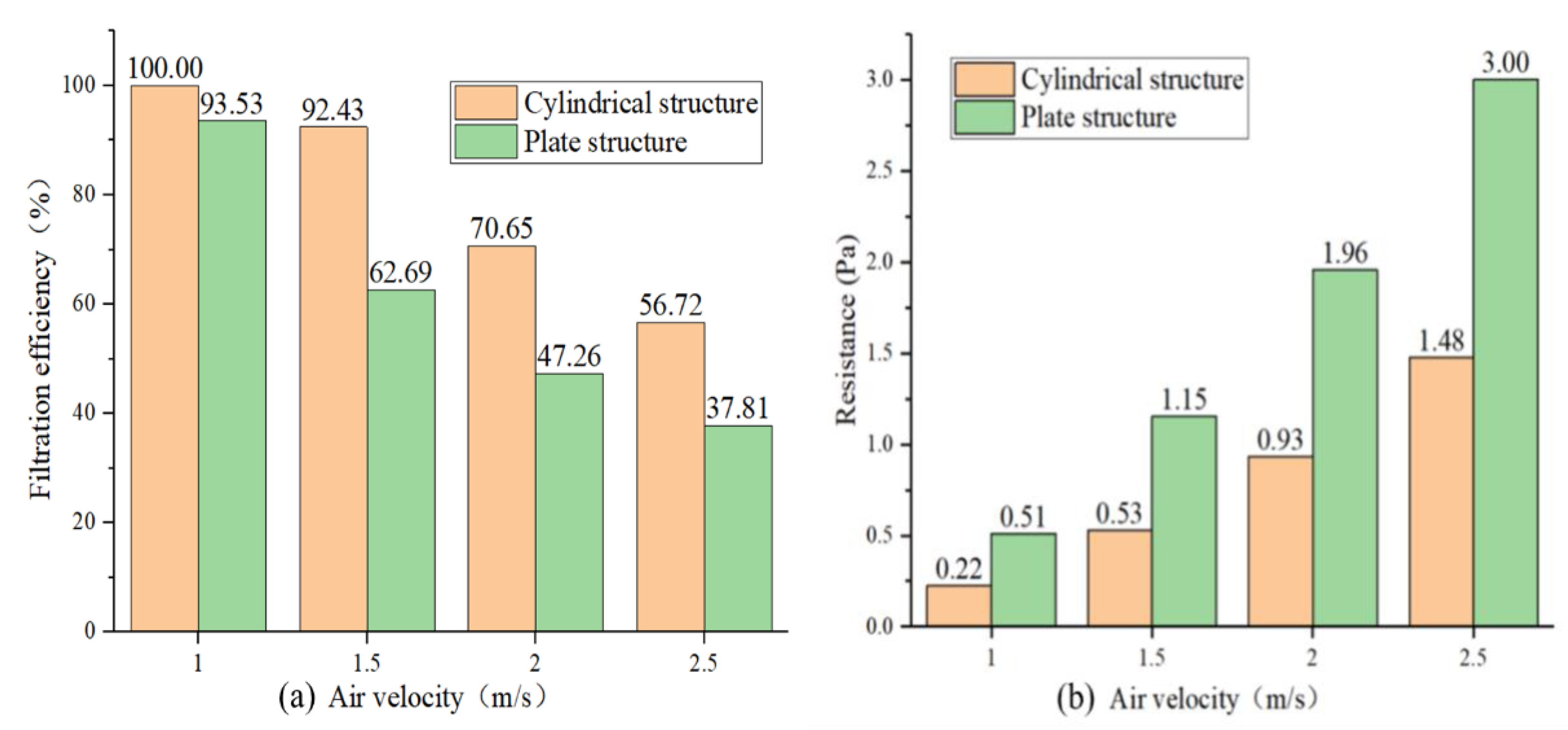
3.3. Cylindrical Structure vs. Plate Structure

The three parameters of particle capture efficiency, airflow resistance, and quality factor, which are often used to evaluate the filtration performance of filters or filter media [58,59,60], are used to evaluate the performance of cylindrical and combined plate-type micro-electrostatic filters. According to the above analysis, the micro-electrostatic filters of the two structures have high filtration efficiency for particles larger than 1 μm under simulated conditions. In other words, the non-single state pathogenic microorganisms and viruses can be effectively captured by the micro-electrostatic filter. However, the single state pathogenic microorganisms and viruses can pass through the micro-electrostatic filter, so it needs to be considered critically. The size of common pathogenic microorganisms and viruses is 0.1 μm~1 μm. Therefore, we select particles of 0.1 μm to compare the minimum filtration efficiency quantitatively. The particle number at the inlet and outlet of the single channel model is counted in the simulation, and the filtration efficiency (η) can be calculated as:
η = 1 N o u t l e t N i n l e t ,
where N i n l e t and N o u t l e t are the number of particles at the inlet and outlet, respectively.
In actual conditions, the resistance of the micro-electrostatic filter ( Δ P ) usually includes local resistance and electric field channel resistance and can be expressed as:
Δ P = P ξ + P S ,
P ξ = ξ ρ u 2 2 ,
P S =   α ρ   u 2 2 ,
where P ξ is the local resistance at the inlet and outlet (Pa), P S is the resistance along the electric field channel (Pa), ξ is the coefficient of local resistance, and α is friction coefficient which comprehensively consider the length, geometric characteristics, and material roughness of the single channel. The single channel resistance calculated in the simulation is P S . It can be seen that the actual resistance of the micro-electrostatic filter should be γ times the single channel resistance, where γ is calculated as:
γ = Δ P P S = ξ ρ u 2 2 + α ρ   u 2 2   α ρ   u 2 2 = ξ α + 1 ,
Since the airflow of the cylindrical micro-electrostatic filter and the combined plate-type micro-electrostatic filter are similar, the ξ value of the filters is the same. Therefore, the resistance of a single channel can reflect the overall resistance characteristics of the micro-electrostatic filter.
Figure 9a shows the filtration efficiency of the two types of micro-electrostatic filters for 0.1 μm particles at different air velocities. It can be seen from the figure that under the same air velocity, the cylindrical structure has a higher filtration efficiency. Within 1.5 m/s~2.5 m/s, the filtration efficiency for 0.1 μm particles of the cylindrical structure is 20%~30% higher than that of the plate structure. The inlet air velocity should be controlled lower than 1.0 m/s~1.5 m/s to ensure high filtration efficiency for 0.1 μm particles. Figure 9b shows the single channel resistance of the cylindrical structure and the plate structure under different inlet air velocities. It can be seen from Figure 9b that under the simulated air velocities, the single channel resistance of the cylindrical structure is almost half that of the plate structure. According to the above analysis, the overall resistance of the cylindrical micro-electrostatic filter should also be half of the combined plate-type micro-electrostatic filter, indicating that the cartridge structure has excellent energy-saving potential.
The quality factor [59] was introduced to evaluate the comprehensive filtration performance of the two types of filters:
Y = l n ( 1 η ) P S ,
The larger the quality factor is, the better the overall performance of the filter. The calculation results of Y are shown in Table 4.
It can be seen from Table 4 that the comprehensive filtration performance of the cylindrical structure is better than that of the plate structure. At 1.0 m/s, because the filter efficiency of the cylindrical structure for 0.1 μm particles is 100%, the quality factor approaches infinity. At 1.5 m/s, 2.0 m/s, and 2.5 m/s, the quality factor of the cylindrical structure is 6 times, 4 times, and 3.5 times that of the plate structure, respectively. In addition, the results in Table 4 also show that reducing the inlet air velocity will significantly improve the overall filtration performance.
Overall, the minimum capture efficiency of the cylindrical micro-electrostatic filter is higher than that of the plate-type electrostatic filter, and the resistance is only 50% of the plate type filter. Under simulated conditions, the quality factor of the cylindrical micro-electrostatic filter is 3.5–6 times that of the plate filter, and the lower the air volume, the more pronounced the advantage. At the same time, according to the analysis in Section 3.1, the cylindrical filter can maintain a higher collection efficiency than the plate filter after holding the dust. Therefore, the filtration performance of the cylindrical micro-electrostatic filter completely surpasses the plate filter.

3.4. Discussion

The filtration performance of the cylindrical micro-electrostatic filter is better than the combined plate-type micro-electrostatic filter due to its unique cross-sectional structure.
As shown in Figure 10, take the movement of a particle in an electric field channel as an example. The particles are subjected to a drag force perpendicular to the direction of the electric field and an electric field force parallel to the direction of the electric field. The direction of the electric field is perpendicular to the direction of the airflow. The trapping efficiency [1,61] of particulate matter can be expressed as:
η = 1 e x p ( ω L υ b ) ,
where ω is the moving velocity of particles in the direction of the electric field (m/s), L is the length of the dust collecting plate (m), v is the moving velocity of the particles in the airflow direction (m/s), and b is the distance between the dust collecting plates (m).
Suppose the dust collecting plate can capture the particle. In that case, the particle’s travel distance in the electric field’s direction is the same as the distance between the dust collecting plate ( b in Equation (15)), and the travel distance in the airflow direction is less than the length of the dust collecting plate ( L in Equation (15)). In this study, the distance between the dust collecting plates ( b in Equation (15)) of the two types of micro-electrostatic filters is the same. That is to say, in the electric field channels of the two types of micro-electrostatic filters, the movement of particles in the direction of the electric field is the same, and the movement time is also the same. Furthermore, along the airflow direction, the cross-sectional area of the electric field channel of the cylindrical micro-electrostatic filter gradually increases, and the airflow velocity in the channel gradually decreases. In contrast, the cross-sectional area of the electric field channel of the combined plate-type micro-electrostatic filter remains unchanged, and the airflow velocity in the channel is also constant. Therefore, in the same movement time, along the airflow direction, the travel distance of the particle in the electric field channel of the cylindrical micro-electrostatic filter is smaller than that of the combined plate-type micro-electrostatic filter. It shows that for the cylindrical micro-electrostatic filter, the particles can be trapped in a smaller length of the dust collecting plate. In other words, the cylindrical micro electrostatic filter has a higher collection efficiency under the same length as the dust collecting plate.
Through simulation studies, the two types of micro-electrostatic filters can achieve almost 100% filtration of microbial aerosols with a particle size larger than 1 μm, and the resistance of the cylindrical micro-electrostatic filter is only 50% of that of the combined plate-type micro-electrostatic filter. This finding indicates that the filtration performance has been dramatically improved. The use of the cylindrical micro-electrostatic filter for indoor HVAC systems has three main advantages. First, it can efficiently capture the indoor pathogenic microorganisms and viruses. Even for monomeric pathogenic microorganisms and viruses (about 0.1 μm), it can achieve a capture efficiency of more than 90%. Second, its resistance is extremely low. According to the literature, the resistance of the plate micro-electrostatic filter can be as low as 14 Pa [20], which is only 7% of the final resistance (200 Pa) of the traditional media filter [7] under the same filtration efficiency. The new cylindrical micro-electrostatic filter proposed in our research also inherits this advantage and has the characteristics of low resistance. It can therefore achieve large air volume operation, which is extremely beneficial to improving the indoor environment. Third, like the electrostatic filter, the micro-electrostatic filter can achieve effective sterilization [19,26] and the ozone emission [20,38] is extremely low, so it will not cause indoor ozone pollution. Finally, the cylindrical micro-electrostatic filter has a lightweight structure and is easy to install. It can meet most of the air volume requirements and resistance requirements in existing HVAC systems. However, only single channel simulation analysis was considered in this study. In actual conditions, the flow velocity at the entrance of different electric field channels is not the same. This non-uniformity of the airflow can lead to an uneven distribution of pollutants. Moreover, the overall filtration efficiency of the filter may be different from the single channel simulation results. Therefore, it is also necessary to perform simulation or experimental research on the overall performance of the cylindrical micro-electrostatic filter.

4. Conclusions

By simulating the movement of particles in an electric field channel, we concluded that the cylindrical micro-electrostatic filter could eliminate the problems of existing plate-type micro-electrostatic filters during long-term use. The cylindrical has a higher filtration efficiency and lower resistance.
Regarding the length of the dust collector and taking particles larger than 1 μm as the criterion, the STL required for the cylindrical micro-electrostatic filter is 17 mm, which is 34% less than that for the plate structure (25 mm). It implies that the volume of the cylindrical micro-electrostatic filter is smaller.
Through theoretical analysis, the relationship between single-channel capture efficiency and filter efficiency is established. Through the calculation of single-channel capture efficiency, for 0.1 μm particles, the minimum capture efficiency of the cylindrical micro-electrostatic filter is 20~30% higher than that of the plate-type electrostatic filter, and the resistance is only 50% of that of the plate-type filter. Under simulated conditions, the quality factor of the cylindrical micro-electrostatic filter is 3.5–6 times that of the plate filter, and the lower the air volume, the more pronounced the advantage. Therefore, the filtration performance of the cylindrical micro-electrostatic filter completely surpasses the plate filter.
Since the cylindrical micro-electrostatic filter has higher efficiency and lower resistance than the plate or media filter, it can run with a larger air volume under the same collection efficiency. Therefore, when it is used in HVAC systems or air purifiers, it is more conducive to creating a healthy indoor environment and reducing health risks.

Author Contributions

Data curation, P.W.; Software, L.K.; Writing–original draft, J.H.; Writing—review and editing, J.L. and X.Z. All authors have read and agreed to the published version of the manuscript.

Funding

This research was funded by China National Key R&D Program ‘energy-saving design and key technical equipment development for clean air conditioning plants’ (Grant No. 2018YFC0705203).

Data Availability Statement

Data obtained from simulations in this study are available on request from the corresponding author.

Conflicts of Interest

The authors declare no conflict of interest.

References

  1. Rahman, M.A.; Zaman, N.; Asyhari, A.T.; Al-Turjman, F.; Alam Bhuiyan, M.Z.; Zolkipli, M.F. Data-Driven Dynamic Clustering Framework for Mitigating the Adverse Economic Impact of Covid-19 Lockdown Practices. Sustain. Cities Soc. 2020, 62, 102372. [Google Scholar] [CrossRef]
  2. Wang, J. Vision of China’s Future Urban Construction Reform: In the Perspective of Comprehensive Prevention and Control for Multi Disasters. Sustain. Cities Soc. 2021, 64, 102511. [Google Scholar] [CrossRef]
  3. Sung, M.; Kato, S.; Kim, M. Development of a Fungal Biosensor for Field Verifying the Surface Disinfection of Ultraviolet Germicidal Irradiation Systems for Air Handling Units. Indoor Built Environ. 2012, 21, 273–281. [Google Scholar] [CrossRef]
  4. Sung, M.; Kato, S.; Yanagi, U.; Kim, M.; Harada, M. Disinfection Performance of Ultraviolet Germicidal Irradiation Systems for the Microbial Contamination on an Evaporative Humidifier. HVACR Res. 2011, 17, 22–30. [Google Scholar] [CrossRef]
  5. Zaatari, M.; Novoselac, A.; Siegel, J. The Relationship between Filter Pressure Drop, Indoor Air Quality, and Energy Consumption in Rooftop HVAC Units. Build. Environ. 2014, 73, 151–161. [Google Scholar] [CrossRef]
  6. Che, W.W.; Tso, C.Y.; Sun, L.; Ip, D.Y.K.; Lee, H.; Chao, C.Y.H.; Lau, A.K.H. Energy Consumption, Indoor Thermal Comfort and Air Quality in a Commercial Office with Retrofitted Heat, Ventilation and Air Conditioning (HVAC) System. Energy Build. 2019, 201, 202–215. [Google Scholar] [CrossRef]
  7. EN 779:2002—New European Test Method for Air Filters. Filtr. Sep. 2003, 40, 22–26. [CrossRef]
  8. Möritz, M.; Peters, H.; Nipko, B.; Rüden, H. Capability of Air Filters to Retain Airborne Bacteria and Molds in Heating, Ventilating and Air-Conditioning (HVAC) Systems. Int. J. Hyg. Environ. Health 2001, 203, 401–409. [Google Scholar] [CrossRef]
  9. Agarwal, N.; Meena, C.S.; Raj, B.P.; Saini, L.; Kumar, A.; Gopalakrishnan, N.; Kumar, A.; Balam, N.B.; Alam, T.; Kapoor, N.R.; et al. Indoor Air Quality Improvement in COVID-19 Pandemic: Review. Sustain. Cities Soc. 2021, 70, 102942. [Google Scholar] [CrossRef]
  10. Clarenburg, L.A.; Werner, R.M. Aerosol Filters. Pressure Drop across Multicomponent Glass Fiber Filters. Ind. Eng. Chem. Process Des. Dev. 1965, 4, 293–299. [Google Scholar] [CrossRef]
  11. Weingartner, E.; Haller, P.; Burtscher, H.; Baltensperger, U. Pressure Drop across Fiber Filters. J. Aerosol Sci. 1996, 27, S639–S640. [Google Scholar] [CrossRef]
  12. Mo, J.; Tian, E.; Pan, J. New Electrostatic Precipitator with Dielectric Coatings to Efficiently and Safely Remove Sub-Micro Particles in the Building Environment. Sustain. Cities Soc. 2020, 55, 102063. [Google Scholar] [CrossRef]
  13. Li, S.; Zhang, S.; Pan, W.; Long, Z.; Yu, T. Experimental and Theoretical Study of the Collection Efficiency of the Two-Stage Electrostatic Precipitator. Powder Technol. 2019, 356, 1–10. [Google Scholar] [CrossRef]
  14. Ren, J.; Liu, J. Fine Particulate Matter Control Performance of a New Kind of Suspended Fan Filter Unit for Use in Office Buildings. Build. Environ. 2019, 149, 468–476. [Google Scholar] [CrossRef]
  15. Jaworek, A.; Marchewicz, A.; Sobczyk, A.T.; Krupa, A.; Czech, T. Two-Stage Electrostatic Precipitator with Dual-Corona Particle Precharger for PM 2.5 Particles Removal. J. Clean. Prod. 2017, 164, 1645–1664. [Google Scholar] [CrossRef]
  16. Jaworek, A.; Marchewicz, A.; Sobczyk, A.T.; Krupa, A.; Czech, T. Two-Stage Electrostatic Precipitators for the Reduction of PM2.5 Particle Emission. Prog. Energy Combust. Sci. 2018, 67, 206–233. [Google Scholar] [CrossRef]
  17. Tian, E.; Gao, Y.; Mo, J. Electrostatically Assisted Air Coarse Filtration for Energy Efficient Ambient Particles Removal: Long-Term Performance in Real Environment and Influencing Factors. Build. Environ. 2019, 164, 106348. [Google Scholar] [CrossRef]
  18. Pushpawela, B.; Jayaratne, R.; Nguy, A.; Morawska, L. Efficiency of Ionizers in Removing Airborne Particles in Indoor Environments. J. Electrost. 2017, 90, 79–84. [Google Scholar] [CrossRef]
  19. Zhou, P.; Yang, Y.; Huang, G.; Lai, A.C.K. Numerical and Experimental Study on Airborne Disinfection by Negative Ions in Air Duct Flow. Build. Environ. 2018, 127, 204–210. [Google Scholar] [CrossRef]
  20. Xiong, W.; Lin, Z.; Zhang, W.; Chen, T.; Zhao, C. Experimental and Simulation Studies on Dust Loading Performance of a Novel Electrostatic Precipitator with Dielectric Barrier Electrodes. Build. Environ. 2018, 144, 119–128. [Google Scholar] [CrossRef]
  21. Nunayon, S.S.; Zhang, H.H.; Jin, X.; Lai, A.C. Experimental Evaluation of Positive and Negative Air Ions Disinfection Efficacy under Different Ventilation Duct Conditions. Build. Environ. 2019, 158, 295–301. [Google Scholar] [CrossRef]
  22. Zhou, P.; Yang, Y.; Lai, A.C.K.; Huang, G. Inactivation of Airborne Bacteria by Cold Plasma in Air Duct Flow. Build. Environ. 2016, 106, 120–130. [Google Scholar] [CrossRef]
  23. Park, C.W.; Hwang, J. Susceptibility Constants of Airborne Bacteria to Dielectric Barrier Discharge for Antibacterial Performance Evaluation. J. Hazard. Mater. 2013, 244–245, 421–428. [Google Scholar] [CrossRef]
  24. Liang, J.L.; Zheng, S.H.; Ye, S.Y. Inactivation of Penicillium Aerosols by Atmospheric Positive Corona Discharge Processing. J. Aerosol Sci. 2012, 54, 103–112. [Google Scholar] [CrossRef]
  25. Chiu, C.M.; Ke, Y.Y.; Chou, T.M.; Lin, Y.J.; Yang, P.K.; Wu, C.C.; Lin, Z.H. Self-Powered Active Antibacterial Clothing through Hybrid Effects of Nanowire-Enhanced Electric Field Electroporation and Controllable Hydrogen Peroxide Generation. Nano Energy 2018, 53, 1–10. [Google Scholar] [CrossRef]
  26. Skowron, K.; Grudlewska, K.; Kwiecińska-Piróg, J.; Gryń, G.; Śrutek, M.; Gospodarek-Komkowska, E. Efficacy of Radiant Catalytic Ionization to Reduce Bacterial Populations in Air and on Different Surfaces. Sci. Total Environ. 2018, 610–611, 111–120. [Google Scholar] [CrossRef]
  27. Wang, Y.; Lin, Z.; Zhang, W. Comparison of Effects of Particle Charging, Media Characteristics, Humidity and Aerosols on Loading Performance of Electret Media. Build. Environ. 2020, 179, 106962. [Google Scholar] [CrossRef]
  28. Sung, J.-H.; Kim, M.; Kim, Y.-J.; Han, B.; Hong, K.-J.; Kim, H.-J. Ultrafine Particle Cleaning Performance of an Ion Spray Electrostatic Air Cleaner Emitting Zero Ozone with Diffusion Charging by Carbon Fiber. Build. Environ. 2019, 166, 106422. [Google Scholar] [CrossRef]
  29. Tu, G.; Song, Q.; Yao, Q. Relationship between Particle Charge and Electrostatic Enhancement of Filter Performance. Powder Technol. 2016, 301, 665–673. [Google Scholar] [CrossRef]
  30. Sobczyk, A.T.; Marchewicz, A.; Krupa, A.; Jaworek, A.; Czech, T.; Śliwiński; Kluk, D.; Ottawa, A.; Charchalis, A. Enhancement of Collection Efficiency for Fly Ash Particles (PM2.5) by Unipolar Agglomerator in Two-Stage Electrostatic Precipitator. Sep. Purif. Technol. 2017, 187, 91–101. [Google Scholar] [CrossRef]
  31. Miyashita, H.; Ehara, Y.; Inui, T.; Aoki, Y. Particle Behavior Analysis in a Hole-Type Electrostatic Precipitator Using PIV. IEEE Trans. Ind. Appl. 2018, 54, 4857–4863. [Google Scholar] [CrossRef]
  32. Eom, Y.S.; Kang, D.H.; Choi, D.H. Numerical Analysis of PM2.5 Particle Collection Efficiency of an Electrostatic Precipitator Integrated with Double Skin Façade in a Residential Home. Build. Environ. 2019, 162, 106245. [Google Scholar] [CrossRef]
  33. Zuraimi, M.S.; Vuotari, M.; Nilsson, G.; Magee, R.; Kemery, B.; Alliston, C. Impact of Dust Loading on Long Term Portable Air Cleaner Performance. Build. Environ. 2017, 112, 261–269. [Google Scholar] [CrossRef]
  34. Guo, C.; Gao, Z.; Shen, J. Emission Rates of Indoor Ozone Emission Devices: A Literature Review. Build. Environ. 2019, 158, 302–318. [Google Scholar] [CrossRef]
  35. Yun, S.J.; Min, B.R.; Seo, Y. A Novel Polymer-Arrayed Electrostatic Precipitator with Electrical Resistance Material for the Removal of Fine Particles. J. Aerosol Sci. 2013, 57, 88–95. [Google Scholar] [CrossRef]
  36. Han, T.T.; Thomas, N.M.; Mainelis, G. Performance of Personal Electrostatic Bioaerosol Sampler (PEBS) When Collecting Airborne Microorganisms. J. Aerosol Sci. 2018, 124, 54–67. [Google Scholar] [CrossRef]
  37. Kim, H.J.; Han, B.; Kim, Y.J.; Yoa, S.J. Characteristics of an Electrostatic Precipitator for Submicron Particles Using Non-Metallic Electrodes and Collection Plates. J. Aerosol Sci. 2010, 41, 987–997. [Google Scholar] [CrossRef]
  38. Kang, G.; Li, L.; Wang, W.; Yu, D. Study of a Polyaniline/Polypropylene Collecting Electrode and Its Particle Removal Efficiency. RSC Adv. 2016, 6, 75038–75044. [Google Scholar] [CrossRef]
  39. Elsaid, A.M.; Ahmed, M.S. Indoor Air Quality Strategies for Air-Conditioning and Ventilation Systems with the Spread of the Global Coronavirus (COVID-19) Epidemic: Improvements and Recommendations. Environ. Res. 2021, 199, 111314. [Google Scholar] [CrossRef]
  40. Farvaresh, E.; Golbabaei, F.; Ghiyaseddin, M.; Behdashti, A.; Nouri-Jaliani, K.; Karimi, M.; Tohidi, S. Investigation of Gas Turbine Intake Air Cooling Via Evaporative Media and Its Effects on Cartridge Filters Pressures Drop. Int. J. Occup. Hyg. 2015, 6, 75–80. [Google Scholar]
  41. Berk, Z. Food Process Engineering and Technology, 2nd ed.; Elsevier Inc.: Amsterdam, The Netherlands, 2013; ISBN 9780124159235. [Google Scholar]
  42. Kanaoka, C. Fine Particle Filtration Technology Using Fiber as Dust Collection Medium. KONA Powder Part J. 2019, 36, 88–113. [Google Scholar] [CrossRef] [Green Version]
  43. Dziubak, T.; Borchet, M. Study of Properties of Nonwoven Filter Cartridges for the Intake Air of a Car Engine. Bull. Mil. Univ. Technol. 2017, 66, 147–148. [Google Scholar] [CrossRef]
  44. Perkowski, C.A. Fermentation Process Air Filtration via Cartridge Filters. Biotechnol. Bioeng. 1983, 25, 1215–1221. [Google Scholar] [CrossRef]
  45. Xu, Y.; Zheng, C.; Liu, Z.; Yan, K. Electrostatic Precipitation of Airborne Bio-Aerosols. J. Electrost. 2013, 71, 204–207. [Google Scholar] [CrossRef]
  46. Lai, A.C.K.; Wong, L.T.; Mui, K.W.; Chan, W.Y.; Yu, H.C. An Experimental Study of Bioaerosol (1–10 µm) Deposition in a Ventilated Chamber. Build. Environ. 2012, 56, 118–126. [Google Scholar] [CrossRef]
  47. Tseng, C.H.; Wang, H.C.; Xiao, N.Y.; Chang, Y.M. Examining the Feasibility of Prediction Models by Monitoring Data and Management Data for Bioaerosols inside Office Buildings. Build. Environ. 2011, 46, 2578–2589. [Google Scholar] [CrossRef]
  48. Li, Y.; Hao, L.; Wang, S.; Hou, L.; Zhang, J.; Qi, J. An Experimental Study on Removal Efficiency of Bio-Particles in an Airtight Decontamination Chamber. Build. Environ. 2009, 44, 2270–2275. [Google Scholar] [CrossRef]
  49. Mui, K.W.; Wong, L.T.; Wu, C.L.; Lai, A.C.K. Numerical Modeling of Exhaled Droplet Nuclei Dispersion and Mixing in Indoor Environments. J. Hazard. Mater. 2009, 167, 736–744. [Google Scholar] [CrossRef]
  50. Gao, N.; Niu, J.; Morawska, L. Distribution of Respiratory Droplets in Enclosed Environments under Different Air Distribution Methods. Build. Simul. 2008, 1, 326–335. [Google Scholar] [CrossRef] [Green Version]
  51. Ruiz-Gil, T.; Acuña, J.J.; Fujiyoshi, S.; Tanaka, D.; Noda, J.; Maruyama, F.; Jorquera, M.A. Airborne Bacterial Communities of Outdoor Environments and Their Associated Influencing Factors. Environ. Int. 2020, 145, 106156. [Google Scholar] [CrossRef]
  52. Dong, M.; Zhou, F.; Zhang, Y.; Shang, Y.; Li, S. Numerical Study on Fine-Particle Charging and Transport Behaviour in Electrostatic Precipitators. Powder Technol. 2018, 330, 210–218. [Google Scholar] [CrossRef]
  53. Atten, P. Collection of Submicron Particles in Electrostatic Precipitators: Influence of EHD Agitation and of Particles Disintegration. Rev. Roum. Sci. Tech. Série Electrotech. Energétique 2010, 55, 161–170. [Google Scholar]
  54. Biskos, G.; Reavell, K.; Collings, N. Electrostatic Characterisation of Corona-Wire Aerosol Chargers. J. Electrost. 2005, 63, 69–82. [Google Scholar] [CrossRef]
  55. Biskos, G.; Reavell, K.; Collings, N. Unipolar Diffusion Charging of Aerosol Particles in the Transition Regime. J. Aerosol Sci. 2005, 36, 247–265. [Google Scholar] [CrossRef]
  56. Cochet, R. Lois: Charge Des Fines Particules (Submicroniques) Etudes Théoriques—Controlesrécentsspectre de Particules. Cent. Nat. Rech. Sci. 1961, 102, 331–338. [Google Scholar]
  57. Moshfegh, A.; Shams, M.; Ahmadi, G.; Ebrahimi, R. A New Expression for Spherical Aerosol Drag in Slip Flow Regime. J. Aerosol Sci. 2010, 41, 384–400. [Google Scholar] [CrossRef]
  58. Leung, W.W.-F.; Hung, C.-H.; Yuen, P.-T. Effect of Face Velocity, Nanofiber Packing Density and Thickness on Filtration Performance of Filters with Nanofibers Coated on a Substrate. Sep. Purif. Technol. 2010, 71, 30–37. [Google Scholar] [CrossRef]
  59. Fisk, W.J.; Faulkner, D.; Palonen, J.; Seppanen, O. Performance and Costs of Particle Air Filtration Technologies. Indoor Air 2002, 12, 223–234. [Google Scholar] [CrossRef] [Green Version]
  60. Huang, S.-H.; Chen, C.-W.; Kuo, Y.-M.; Lai, C.-Y.; McKay, R.; Chen, C.-C. Factors Affecting Filter Penetration and Quality Factor of Particulate Respirators. Aerosol Air Qual. Res. 2013, 13, 162–171. [Google Scholar] [CrossRef]
  61. Deutsch, W. Bewegung Und Ladung Der Elektrizitätsträger Im Zylinderkondensator. Ann. Phys. 1922, 373, 335–344. [Google Scholar] [CrossRef] [Green Version]
Figure 1. Schematic diagram of the filter structure and airflow direction; (a) combined plate micro-electrostatic filter; (b) cylindrical micro-electrostatic filter.
Buildings 11 00465 g001
Figure 2. Schematic diagram of the research method.
Buildings 11 00465 g002
Figure 3. Schematic diagram of the single channel simulation geometric model.
Buildings 11 00465 g003
Figure 4. Schematic diagram of the single channel analog meshing.
Buildings 11 00465 g004
Figure 5. Model verification results: (a) fractional efficiency by particle size; (b) electric field simulation results of single channel; (c) velocity field simulation results of single channel.
Buildings 11 00465 g005
Figure 6. Movement of particles in the electric channels of the two types of micro-electrostatic filters under different dust-collection plate voltages: (a,c,e) show the particle movement of the combined plate-type micro-electrostatic filter at 10.0 kV, 8.0 kV, and 6.0 kV; (b,d,f) show the particle movement of the cylindrical micro-electrostatic filter at 10.0 kV, 8.0 kV, and 6.0 kV.
Buildings 11 00465 g006
Figure 7. Movement of particles in the two micro-electrostatic filter channels under different air velocities: (a,c,e,g) show the combined plate-type micro-electrostatic filter at 2.5 m/s, 2.0 m/s, 1.5 m/s, and 1.0 m/s; (b,d,f,h) show the movement of particles in the cylindrical micro-electrostatic filter at 2.5 m/s, 2.0 m/s, 1.5 m/s, and 1.0 m/s.
Buildings 11 00465 g007
Figure 8. Theoretical STL required by the micro-electrostatic filters to capture particles of various sizes.
Buildings 11 00465 g008
Figure 9. The filtration performance of the two types of micro-electrostatic filters: (a) the filtration efficiency of the two types of micro-electrostatic filters for 0.1 μm particles at different air velocities; (b) the single channel resistance of the two structures.
Buildings 11 00465 g009
Figure 10. Schematic diagram of the movement of particles in the electric field channel.
Buildings 11 00465 g010
Table 1. Constants used in the single channel simulation.
ParametersValue
Polypropylene resistivity1 × 1019 Ω·m
Relative permittivity of polypropylene2.2
Aerodynamic viscosity18 × 10−6 Pa·s
Particle density2200 kg/m3
Air density1.29 kg/m3
Elementary charge1.6 × 10−19 C
Table 2. Parameters in plate-type micro-electrostatic filter simulation.
ParametersValue
Length of collecting plate55 mm
Inlet and outlet of the single channel2 mm × 4 mm
Voltage of collecting plate10.0 kV
Particle density3000 kg/m3
Air velocity1.0 m/s
Table 3. Fractional efficiency by particle size.
Particle Size0.4 μm0.6 μm0.8 μm
Filtration Efficiency99.8%99.9%100.0%
Table 4. The calculation results of quality factor Y .
Air Velocity (m/s)1.01.52.02.5
Y Cylindrical Structure5.171.310.57
Plate Structure5.370.860.330.16
Publisher’s Note: MDPI stays neutral with regard to jurisdictional claims in published maps and institutional affiliations.

