Article

Optimum Design of RC Footings with Genetic Algorithms According to ACI 318-19

Department of Civil Engineering and Energy Technology, OsloMet—Oslo Metropolitan University, 0167 Oslo, Norway
*
Author to whom correspondence should be addressed.
Buildings 2020, 10(6), 110; https://doi.org/10.3390/buildings10060110
Submission received: 27 May 2020 / Revised: 8 June 2020 / Accepted: 9 June 2020 / Published: 11 June 2020

Abstract

:
Engineers usually use trial-and-error approaches for dealing with design problems where they need to find the most economical design of a structural element in terms of its material cost while satisfying all the safety requirements imposed by the design codes. In this study, we employ a genetic algorithm (GA) with a dominance-based tournament selection technique for dealing with this design challenge. The methodology is applied in the design of reinforced concrete rectangular-shaped isolated footings in accordance with the American Concrete Institute ACI 318-19. First, the footing is encoded into a set of decision variables and an objective function is defined to compute the total cost based on the different construction materials. Then, the compliance of the design with the ACI 318-19 code is enforced by a constraint function that takes into consideration all the demand–capacity ratios for the different resistance requirements such as the allowable bearing pressure of the supporting soil, and the shear and flexural capacities of the footing, among others. Two numerical examples are presented where the results show a significant advantage in terms of material-cost and design-time reduction in comparison with the commonly used trial and error approach, proving the applicability of optimization algorithms (OAs) into the everyday design routine of the structural engineer.

Graphical Abstract

1. Introduction

With the development of modern computing, optimization algorithms (OAs) have emerged as powerful design tools in practically all fields of engineering. In the construction industry, most times optimization is only applied locally to a few specific “key” components of the design, but it is still considered over-complicated to be applied at a full scale to broader design problems. One of the reasons for this is that the design of these elements usually requires fast, reliable, and sometimes on-the-go solutions for which the complexity of an optimization algorithm seems to be not worth the benefits obtained compared to traditional trial-and-error approaches, which take advantage of the experience of the engineer. This conception is changing rapidly nowadays with the development of ready-to-use optimization tools and libraries that require either a small amount of coding or are based on a user-friendly interface that takes the coding complexity away. When such computational tools are used, it only takes some basic understanding of the underlying concepts of optimization to successfully implement it into the everyday-design problems that the structural engineer faces during the design of buildings and structures [1].
The motivation for using modern computational techniques to optimize the structural design of a construction comes as an answer to the fact that the construction industry consumes a huge amount of resources, which contributes to a high amount of greenhouse gas emissions. Buildings and construction generate nearly 40% of global CO2 emissions according to the 2019 Global Status Report [2] published by the Global Alliance for Buildings and Construction (GlobalABC) of the UN. The fast-required solutions of the construction industry many times outweigh an efficient usage of construction materials. A much more efficient resource usage and lower carbon footprint can be achieved by integrating modern optimization techniques into the everyday design process of structural elements, without compromising the safety or the speed of the design process.
The main goal of this study is to set an example of how the problem of the design of structural elements, such as reinforced concrete (RC) footings, can be transformed to a well-defined optimization problem that can then be computationally handled and solved by an OA. The genetic algorithm, a well-established OA inspired by the natural evolution process, has been used in the study because of its elegance, robustness, and reliability in handling various types of optimization problems. Genetic algorithms (GAs) have been successfully used for solving highly non-linear problems in various engineering disciplines [3].
Optimization techniques have been successfully used for the design of various reinforced concrete structures [4,5]. Coello et al. [6] applied a simple GA for the design of RC elements, where the aim was to minimize the cost of a reinforced concrete rectangular beam based on strength design procedures, while also considering the costs of concrete, steel, and shuttering. In Luévanos-Rojas et al. [7,8], optimization was applied to the design of concrete footings using a soil pressure model that requires the computation of several integrals in the constraint functions. Chaudhuri et al. [9] used GA and unified particle swarm optimization (UPSO) strategies for the design of footings according to IS 456 2000, showing that both implementations produce noticeable better solutions than some popular structural design commercial packages in terms of material cost. Khajehzadeh et al. [10] presents an interesting multi-objective optimization (MOO) approach for the design of spread footings, where one of the objective functions quantifies the total amount of CO2 emissions resulting from the material usage. The MOO problem is solved using a novel global–local gravitational search algorithm. Al-Ansari [11] proposes an iterative optimization method for RC footings with a sophisticated analytical model that computes the total cost of the footing including a high level of detail such as the timber formwork and rebar dowels length. Other metaheuristic techniques have been also successfully implemented for the design of RC footings, such as in Nigdeli et al. [12] where harmony-search (HS), teaching–learning-based optimization (TLBO), and flower pollination algorithm (FPA) have been used with successful results.
In this paper, an optimization methodology to find the most economical structural design using GAs is developed. A problem is defined where the total material cost of the structural element is used as an objective function to be minimized, and the compliance of the building design code is enforced by a constraint function that takes into account all of its design requirements. The methodology is tested for the design of RC footings within the scope of the building code requirements for concrete structures by the American Concrete Institute ACI 318-19 [13]. For a given set of reaction forces and other input parameters, the algorithm will find the optimum dimensions of the RC footing and the amount of steel reinforcement that lead to the lowest material cost while satisfying all the design criteria for footing design stablished in the ACI 318-19 code.

2. The Optimization Problem

2.1. Basic Principles of Design

The design of a structural element needs to comply to all the safety and strength requirements provided in the governing building design code, from now on, each of these requirements will be denoted as a “design check”. Each design check can be understood as the comparison of a characteristic or property of a structural element (capacity) against the permitted or required value provided in the building design code (demand). In general, the capacity of the structural element has to be larger than the demand and this comparison can be expressed in form of the demand–capacity ratio d/c of the actual value c (capacity, e.g., element strength) against the required value d (demand, e.g., actual stress) of the property in question. The ideal scenario is when the element demand is slightly less than its capacity, i.e., d/c ≈ 1, meaning that the design is structurally efficient and also economic.
The goal of the structural designer is to achieve the best cost-effective design in order to maintain the viability of the project. For that purpose, finding the most economical solution for as many structural elements as possible is essential. This may be a non-trivial task for specific structural elements that are required to comply with multiple design checks under various loading conditions and combinations of loads. For example, a RC column must be able to resist both axial forces (vertical loads) and bending moments (due to lateral loads). In some scenarios, the resistance to vertical loads could be improved by simply increasing the compressive strength of the concrete and the cost would not change considerably. However, for the lateral loads, probably adding additional steel reinforcement would be the simplest option but it could elevate the cost significantly. As a result, the solution to achieve the most cost-effective overall solution is not always obvious.

2.2. Encoding the Problem in Decision Variables

The first step is to encode the structural element into n decision variables z1, z2,…, zn, where n is the dimensionality of the optimization problem. These variables represent the element properties which are possible to change during the design phase, such as the geometrical dimensions and others. For each decision variable zj, a specific range [zj,min, zj,max] and domain must be defined. For continuous search spaces it is usually zj ∈ ℝ. The encoded structural element e can then be written as a vector of the decision variables as follows:
e = [ z 1 , z 2 , , z n ]

2.3. Objective Function

The optimal design is defined in terms of the material cost of the structural element; therefore, the optimization task becomes a minimization problem where the set of design variables that leads to the minimum material cost of the structural element are to be found. In the general case with m different materials used for the construction of the structural element, the element cost is given by
f ( e ) = j = 1 m v j c j
where vj is the volume of material j and cj is the perspective material volumetric cost. Other cost parameters such as the labor cost, the form-work in concrete elements, or the welding in steel constructions could be easily added as additional terms in Equation (1), yet the present study focuses only on the material cost, i.e., the cost of concrete and steel of the RC element.

2.4. Defining the Constraint Function

To define the constraint function, all the design checks that apply to the design of the structural element in question are identified in the building design code and converted into a d/c ratio where for a safe design check, it is a d/c ≤ 1. For each design check, we define the exceeding ratio er as follows
e r j = { ( d / c ) j 1   if   ( d / c ) j > 1 0 otherwise
The constraint function g(e) is then the summation of the exceeding ratios er of all design checks applied to the structural element. Assuming that for the structural element e there is a number ndc of design checks to comply to, the constraint function is written as
g 1 ( e ) = j = 1 n d c e r j
which means that g1(e) = 0 denotes a safe design that satisfies all the ndc design checks.

3. Solving the Optimization Problem

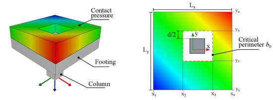
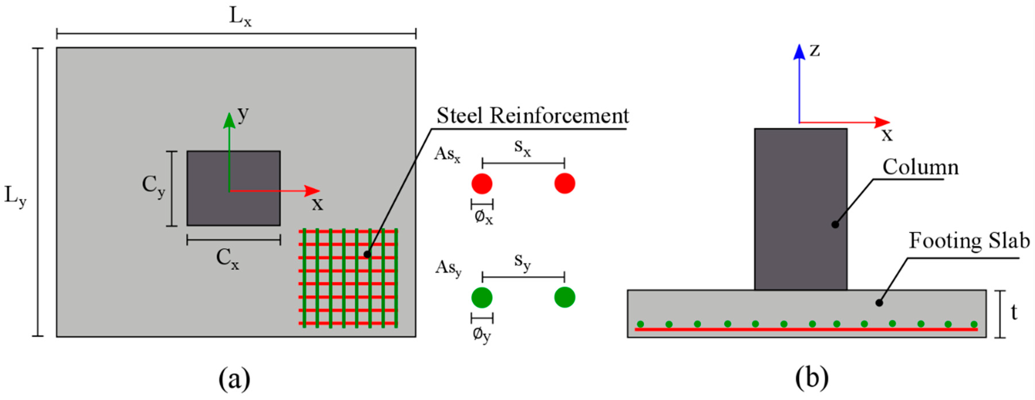
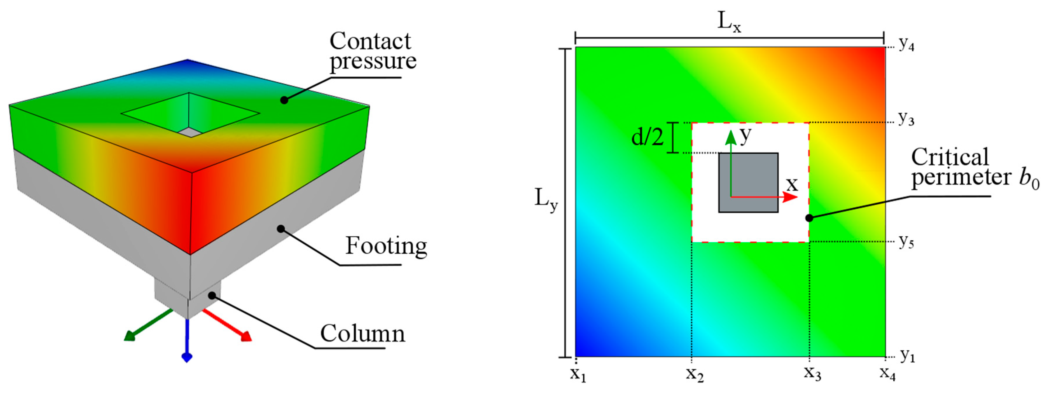
3.1. Foundamentals of Genetic Algorithms

GAs are based on the principle of genetic evolution in which only the best or “fittest” individuals of a population survive to reproduce and create the next generation. During the process, some genes of the new-born individuals are randomly mutated. This operation introduces new changes that could make an individual stronger to survive in its environment, and therefore, more likely to reproduce and pass those advantages to the next generation.
In the mathematical analogy a population consist of several design vectors (individuals), each design vector is composed of a set of design variables (chromosomes) that can be modified within a specific domain or search space during the algorithm execution. In the case of single-objective optimization problems, a single objective function that assigns a fitness value to the design vectors is defined. The natural processes of selection, reproduction and mutation are simulated through numerical operations. At every iteration (or generation), the best design vectors of the population based on their fitness value are selected, combined, and mutated to create a new stronger population. The algorithm usually stops after a certain number of generations is completed, if no improvement is observed after a specific number of iterations or if another convergence criterion is satisfied.

3.2. Genetic Algorithm with Elitism

The solution to the optimization problem is found by applying a single objective GA with elitism. The algorithm used for the present study is briefly described in the following steps [14].
Step 1. Initialization. The algorithm starts at i = 0 by randomly generating multiple design vectors e1, e2,…, es on a search space that is based on their pre-specified domain and ranges. Each design vector is denoted as an individual and all together they form the initial population Pi, which has a size of s = 100 individuals.
Step 2. Objective and constraint function evaluation. The objective and the constraint values are computed for all the individuals of the current population Pi based on Equations (2) and (4), respectively.
Step 3. Selection of the fittest. The best individuals from the current population are chosen following the dominance-based tournament selection operator [15]. This operator takes two random individuals from the current population {ea, eb} ∈ Pi to be compared or “fight” against each other. The winner of the fight is chosen according to the following dominance criteria, where the symbol denotes dominance of a design over another:
  • A solution ea that fulfils the constraint dominates a solution eb that does not.
    if   ( g ( e a ) = 0 and g ( e b ) > 0 ) then e a e b
  • If both solutions fulfil the constraint, the one with the lowest objective value dominates the other.
    if   [ ( g ( e a ) = g ( e b ) = 0 and f ( e a ) < f ( e b ) ) ] then e a e b
  • If both solutions violate the equality constraint, the one with the lowest constraint value dominates the other.
    if   [ ( g ( e a ) > 0 and g ( e b ) > 0 ) and ( g ( e a ) < g ( e b ) ) ] then e a e b
After the winner of the first encounter is obtained, a new opponent is chosen randomly from the current population to “fight” against the previous winner. This battling process is repeated for a specific number of times known as tournament size ts. The winner of the final fight is the champion of the tournament, and the outcome of the selection operator.
Since only one individual is selected per tournament, the process is repeated multiple times until a set SiPi that contains a number s∙0.20 = 100∙0.20 = 20 of individuals is obtained. After every tournament, the champion is removed from the available pool to avoid selecting the same individual multiple times.
Step 4. Crossover. The goal of the crossover operation is to generate new elements by the reproduction of the strongest individuals. From the previously created pool Si, two individuals {eI, eII} ∈ Si are chosen and their decision variables (chromosomes) are combined to obtain two new offspring {ex, ey} ∈ Qi. The selection process is repeated until Qi has a total of s∙0.80 = 100∙0.80 = 80 individuals. The simulated binary crossover algorithm (SBX) [16] is used for this operation.
crossover ( S i ) = Q i
Step 5. Mutation. The mutation operation is introduced to the newly created population Qi. The main purpose of the mutation is to maintain diversity and avoid the problem of getting trapped into a local minimum. The mutation operator produces a small change to the decision variables using the polynomial mutation scheme [17]. The mutation is applied with a probability of 1/n, so that on average, one variable per individual is mutated.
P i + 1 = mutation ( Q i ) S i
Notice that elitism preservation is achieved by passing the selected elements Si unchanged to the next population. This feature has proven to improve the efficiency of the algorithm by avoiding that good solutions are degraded by the mutation or crossover operators.
Step 6. Termination. With the newly created population Pi+1, steps 2–5 of the process are repeated until a termination criterion is met. In this study, the algorithm stops after the objective function has been evaluated MAXEVAL number of times. The design vector with the lowest objective value of the final population is selected as the solution to the optimization problem.
Figure 1 shows a flowchart of the GA procedures described in the above steps 1–6.

4. Optimum Design of RC Rectangular Footings

The previously described methodology is applied to the design of rectangular footings in accordance with the American Concrete Institute Building Code Requirements, ACI 318-19 [13]. In this section, a brief insight on the design procedures is provided. For a more detailed description, the interested reader is referred to [18,19]. Concrete footings have been chosen as an example of the applicability of optimization algorithms in structural engineering because of the complexity of their design where all design checks share a certain degree of dependency making the design process particularly challenging.
The rectangular footing is first encoded into a total of five design variables, three for the geometrical dimensions of the slab (horizontal dimensions Lx, Ly and thickness t) and two for the steel reinforcement (areas Asx, Asy), as shown in Figure 2.
The design principles are based on the stresses generated on the soil and the concrete slab due to the contact/bearing pressure acting between them. Such pressure is assumed to be linearly or uniformly distributed along the contact area depending on whether or not there are eccentricities on the axial load or moments acting on the column, as shown in Figure 3.
For any point (x, y) inside the contact area, where (x = 0, y = 0) denotes the center point of the slab, the bearing pressure is computed as
σ ( x , y ) = F z L x L y ± 12 M x y L x L y 3 ± 12 M y x L y L x 3
Notice that Equation (10) depends solely on the geometrical properties and the acting forces in the footing. This is due to the assumption that the concrete slab is considered as a rigid body. Furthermore, Equation (10) is only valid when the full area of the footing is in contact with the soil (no uplift of the footing). With the definition of Equation (10), the pressure applied on the soil or the stresses generated on specific sections of the concrete slab can be accurately computed and compared with the corresponding resistance, according to the design code provisions.

4.1. Rectangular Footing Design Checks

The design requirements for two-way isolated RC footings are given in Sections 13.3.1 and 13.3.3 of ACI 318-19. The four principal design checks that must be satisfied are briefly described in the next section. Note that in the following formulas, the stresses are considered in MPa and the geometrical dimensions in meters. A description of the various variables used is given in Table 1.
Design check 1: Allowable soil pressure (section 13.3.1.1). Sufficient contact area must be provided so that the maximum generated bearing pressure σ(x,y)max should not exceed the soil’s allowable pressure qa. The allowable soil pressure must be determined by principles of soil mechanics in accordance with the general building code.
( d / c ) 1 = σ ( x , y ) max / q a
Design check 2: One-way shear resistance (sections 8.5.3.1.1/22.5.1.2). The critical section for one-way shear is located at a distance d from the edge of the column. For rectangular footings with rectangular columns this condition leads to the possibility to have up to four critical sections, two parallel to the x direction and two parallel to the y direction. The shear strength ΦsVn at every critical section must be sufficient to resist the corresponding acting shear force Vu. The shear strength of a concrete section can be computed as follows
V u ϕ s ( V c + 0.66 f c b w d )
V c = ( 0.17 λ f c + N u 6 A g ) b w d
The acting shear force Vu at the critical sections is obtained by integrating the bearing pressure over the corresponding area, as shown in Equations (14), (15) and Figure 4.
V u , x 1 = x 1 x 2 y 1 y 4 σ ( x , y ) d x d y
V u , x 2 = x 3 x 4 y 1 y 4 σ ( x , y ) d x d y
Notice that only the critical sections and shear forces perpendicular to the x direction are shown in Equations (14), (15) and Figure 4. The critical sections perpendicular to y should also be checked in a similar way. The demand–capacity ratio (d/c)2 will be taken as the maximum of the four analyzed critical sections.
( d / c ) 2 = V u / ( ϕ s V n )
Design check 3: Flexural resistance (section 8.5.2.1/22.3). The critical section for flexion is located at the edge of the column. Similar to the one-way shear check, for a rectangular column there could be four critical sections, two in each of the orthogonal x and y directions. The moment capacity ΦfMn at each of the critical sections must be sufficient to resist the corresponding acting bending moment Mu. The moment capacity of a concrete section can be computed as follows
M u ϕ f M n
M n = A s f y ( d β 1 c 2 )
c = A s f y β 1 0.85 f c b w
β 1 = { 0.85 17 f c 27 0.85 0.05 ( f c 28 ) 7 27 < f c < 55 0.65 f c 55
The acting bending moment Mu at the critical sections is obtained by integrating the bearing pressure over its corresponding area and multiplying it with its lever arm to the critical section as shown in Equations (21), (22) and Figure 5.
M u , x 1 = x 1 x 2 y 1 y 4 σ ( x , y ) ( x x 2 ) d x d y
M u , x 2 = x 3 x 4 y 1 y 4 σ ( x , y ) ( x x 3 ) d x d y
Notice that only the critical sections and bending moments perpendicular to the x direction are shown in Equations (21), (22) and Figure 5. Similarly, the critical sections perpendicular to y should also be checked. The demand–capacity ratio (d/c)3 will be taken as the maximum of the four analyzed critical sections.
( d / c ) 3 = M u / ( ϕ f M n )
Design check 4: Two-way or punching shear resistance (sections 8.5.3.1.2/22.6.5.2). The critical section for two-way or punching shear is the perimeter b0 located at a distance d/2 from the column. The shear strength ΦsVn of this section must be sufficient to resist the acting shear force Vu that is generated by the bearing pressure which produces a punching stress near the column edges. The punching shear strength Vn will be taken as the minimum of three formulas, as shown below
V n = min { 0.33 λ s λ f c b 0 d 0.17 ( 1 + 2 β ) λ s λ f c b 0 d 0.083 ( 2 + a s d b 0 ) λ s f c b 0 d
λ s = 2 1 + 0.004 d 1
a s = { 40 interor   columns 30 edge   columns 20 corner   columns
The acting shear force Vu at the critical section is obtained by integrating the bearing pressure over its corresponding area to the critical section as shown in Equation (28) and Figure 6. The demand capacity ratio (d/c)4 is then computed as follows:
( d / c ) 4 = V u / ( ϕ s V n )
V u = x 1 x 4 y 1 y 4 σ ( x , y ) d x d y x 2 x 3 y 2 y 3 σ ( x , y ) d x d y

4.2. Additional Constraints

Section 2 described the optimization methodology in a general form. The objective and the demand–capacity ratio constraint functions are the core elements of the methodology. However, some structural elements may require additional constraints to ensure that meaningful results will be produced from the optimizer. In the case of rectangular footings, due to the bi-directional nature of the design, an additional constraint has been defined to prevent the undesired characteristic of having one side several times longer than the other orthogonal side. Such characteristic could be more economical in terms of material cost but not practical for construction purposes. To prevent this, a second constraint function g(e)2 is introduced that limits the dimensions to a maximum long-to-short side ratio denoted as βmax. This additional parameter can be easily modified to allow for any desired ratio before running the optimizer.
g 2 ( e ) = max ( L x , L y ) min ( L x , L y ) = β β max

4.3. Optimization Problem Definition Particularly for the Design of Rectangular Footings

Now that all the required equations and concepts were defined, the optimization problem can be formally written. In this case, there are m = 2 materials and the objective function to be minimized can be written as
f ( e ) = j = 1 2 v j c j
where c1, c2 are the unit costs of concrete and steel, respectively, and v1, v2 are the volumes of concrete and steel, respectively, that can be expressed as
v 1 = L x L y t
v 2 = A s x L x + A s y L y
The two constraint functions are the following
g 1 ( e ) = j = 1 4 e r j = 0
g 2 ( e ) β max

5. Numerical Examples

Two numerical examples are examined in order to test the methodology and the efficiency of the optimization procedure. Both dead and live loads are taken into consideration. The three load combinations are presented in Table 2. The first design check corresponding to the soil capacity only considers the service load combination while the other three design checks (one directional shear, punching shear and flexural design) consider the ultimate load combinations U1 and U2.
The methodology has been implemented into a custom-made application specifically for the design of rectangular RC footings, using the Java programming language. The applied GA is a combination of self-coding and the use of the open source package MOEA Framework. The 3D graphics are generated using the JavaFX package.
The population size of the GA is s = 100, while the tournament size is ts = 5. The algorithm stops after the objective function has been evaluated MAXEVAL = 10,000 times. The parameter βmax having to do with the maximum long-to-short length ratio described in Equation (34), is set to 1.5. The material properties used in both examples are shown in Table 3. We did not use real monetary values for the cost of concrete and steel, as these values may vary with time and the exact values are not important for this study. What is important is the relative cost of concrete and steel. We assume that the cost of steel is 15 times higher than the corresponding cost of concrete, in volume terms, which is a reasonable assumption based on the current prices of the two materials in most European markets.
The design variables of the optimization problem are presented in Table 4 with their minimum and maximum range. All variables are continuous, defined in the ℝ domain.

5.1. Example 1: Rectangular Footing with Square Eccentric Column

The first example consists of the design of a rectangular footing with a column cross section of 50 × 50 cm. The column has an eccentricity of 20 cm to the footing center in the x-direction. The loading conditions are given in Table 5.
The progression of the algorithm is shown in Figure 7. Each data point in the plot corresponds to a feasible design computed during the algorithm execution. The x axis shows the number of function evaluations while the y axis shows the objective function value. Because of the population size (s = 100), 100 function evaluations correspond to one generation. In the first function evaluations, there is a high variance in the data points because at this stage the algorithm is exploring a large area of the search space. As the algorithm progresses further, the selection operator prevents the solutions with a high objective value to pass to the next generations and the search space is greatly reduced in the direction of the global minimum. A plot of the standard deviation of the objective values of all the individuals of each generation is presented in Figure 8.
The optimum design vector eopt and its corresponding objective value f(eopt) are shown in Table 6. The demand–capacity ratios of the optimum design vector achieved by the algorithm are shown in Table 7, where an asterisk (*) denotes an active constraint. The first, third and fourth d/c constraints appear to be active at the optimum, with values close to one. The β parameter takes a value of 1.4995 < 1.5 at the optimum, which also indicates an active constraint. Figure 9 shows the geometry of the final design eopt and the contact pressure corresponding to the service load combination.

5.2. Example 2: Rectangular Footing with Rectangular Center Column

For the second test example, the optimum design of a rectangular footing with a rectangular cross section of 50 × 80 cm is sought. The column has a reaction force of −1600 kN and −900 kN corresponding to the dead and live load cases, respectively. In this example, there are no eccentricities or moments acting on the column. Similarly, to the results presented in the previous example, the progression of the algorithm is displayed in Figure 10.
The results are shown Table 8 and Table 9. Again, three of the d/c ratios appear to be active as constraints at the optimum, with values close to one. One the other hand, the β parameter takes a value of 1.23 < 1.5 at the optimum, which indicates that this constraint is not active at the optimum.
In order to verify the results, the values of the optimum design vector are substituted back into Equations (10) and (11), to compute (d/c)1. Due to the uniformity of the bearing pressure acting on the soil, the shear forces and the bending moments on the critical sections can be computed easily without the need of numerical integrations.
σ max = 1600 + 900 + 80.21 2.139 3.021 = 399.29   kPa
( d / c ) 1 = 399.29 400 = 0.998 < 1
Note that the self-weight of the footing is included in the above calculation and it has a value of 80.21 kN. Similarly, using the optimum design vector and Equations (10), (24), (27), and (28), the (d/c)3 ratio is computed as follows
σ u = 1600 1.2 + 900 1.6 + 80.21 2.139 3.021 = 532.38   kPa
V u = 532.38 2.139 3.021 532.38 1.24 0.94 = 2819.65   kN
b 0 = ( 1.24 + 0.94 ) 2 = 4.36
d = 0.491 0.05 = 0.441
V n = 0.75 0.33 35 4.36 0.441 = 2815.36   kN
( d / c ) 3 = 2819.65 2815.36 = 1.001 1
The values slightly differ with those found by the algorithm by a few decimals due to the rounding operations done in the hand-calculations. The computer uses double precision variables and the real value of (d/c)3 is in fact equal to 0.999 when all the decimals are considered.

5.3. Discussion of the Results

In both examples, the optimizer has achieved a demand–capacity ratio close to 1.0 for three out of four design checks. This corroborates a successful implementation of the methodology as further reduction of the cost would not be possible without exceeding the element capacity in at least one of its design checks. The results show that the dimensions Lx and Ly of the slab are controlled by the allowable soil pressure (d/c)1, while the thickness is controlled by the punching shear (d/c)3 and the flexural capacity (d/c)4 as shown in Equations (35) to (41). The optimum dimensions of the slab for both examples exhibit a rectangular shape, this is due to the eccentricity present in example 1 and the rectangular shape of the column in example 2. The second constraint related to the factor βmax in Equation (29) is also active for example 2, this constraint is particularly useful when a certain shape is required (i.e., forcing a square-shaped slab by setting βmax ≈ 1.0).
In terms of computational cost, the developed methodology shows high efficiency with a total execution time for 10,000 function evaluations of only 4.8 s on a regular personal computer with a i7-8550U 1.80 GHz CPU. The most computationally expensive operation is the numerical integration required to obtain the total acting forces and moments. The developed algorithm could be additionally optimized for faster computational speed, but this is not the main focus of this study.
The obtained optimum design for both examples is most likely to be a local minimum since the design space appears to be highly non-convex. Two different executions of the algorithm with the same parameters could lead to slightly different results, which is partly due to the stochastic nature of the GA and partly because of the local minima in the design space. Therefore, achieving the global minimum is a particularly challenging computational task and there is no guarantee that it will be reached in the end. Nevertheless, the obtained design is always very close to the global optimum and from an engineering point of view it is a well-suited solution to the problem.

6. Conclusions

A systematic methodology for optimizing the design of structural elements in terms of their economical cost while satisfying all the safety and strength requirements imposed by the governing building design code has been developed by means of a GA with elitism. The method was successfully applied in two examples for the design of RC isolated footings in accordance with the ACI 318-19. The input parameters include the dimensions and reactions of the column along with the strength of the construction materials used. The design of the footing is checked to satisfy the ACI 318-19 requirements for the allowable bearing pressure, one-way shear, punching shear, and flexural resistance. The results in both examples shows that 3 out of 4 design checks are active with a demand–capacity ratio close to 1.0, which indicates that further reduction of the cost is probably not possible, and thus, confirms that the obtained design is close to optimum in terms of the economic cost.
This study shows that OAs and in particular GA, can be practically applied to the design of structural elements reducing the time and effort of the everyday-design routine of the engineer. The main advantages of the methodology are highlighted as follows:
  • High computational efficiency. The computational cost of the methodology is relatively low with an execution time of only 4.8 s in the examined cases.
  • Reduction of the design process time. The traditional design process of trial and error is replaced by an automated design that finds the optimum dimensions quickly. This allows the engineer to avoid repetitive design routines and focus on the big picture, the design control, and other more important features of the overall design process.
  • Simple implementation. While it is true that some expertise and coding abilities are necessary in order to successfully implement OAs, this trend is rapidly changing with the development of more user-friendly optimization commercial packages (i.e., MATLAB, MAPLE) that greatly reduce the computational complexity. Therefore, the requirements for implementing the methodology for its practical usage narrows down to the proper definition of the optimization problem itself, which has been clearly presented in this study.
  • More efficient usage of material. By minimizing the cost of a structural element with modern optimization techniques, less material is used compared to the traditional trial-and-error methods without compromising the required level of safety and reliability of the structure. The exact cost reduction depends on the complexity of the design problem, but it can easily be in the order of 10%–20%. This is a remarkable achievement not only from an economical point of view, but also in terms of the environmental impact. A more efficient usage of the construction materials can significantly help to reduce the high carbon footprint of the construction industry.

7. Future Work

It is of great interest to expand and test the methodology for the design of more complex structural elements such as reinforced concrete columns or shear walls. Having an optimum and automated design routine of all the structural elements present in a building could open the possibility of obtaining a cost-efficient structural design of the whole building in a very short time. This can have great implications on the overall efficiency of the structural design process.
Although GA was successfully used in this study, the methodology can be easily adapted for its use with other modern optimization algorithms such as particle swarm optimization [20], differential evolution [21], and others. By doing so, a comparative study could be conducted to select the most efficient algorithm for the examined optimization problem.

Author Contributions

Conceptualization, G.S. and V.P.; methodology, G.S.; software, G.S.; validation, V.P.; formal analysis, G.S. and V.P.; investigation, G.S. and V.P.; resources, G.S. and V.P.; data curation, G.S.; writing—original draft preparation, G.S.; writing—review and editing, V.P.; visualization, G.S.; and supervision, V.P. All authors have read and agreed to the published version of the manuscript.

Funding

This research received no external funding.

Conflicts of Interest

The authors declare no conflict of interest.

References

  1. Plevris, V.; Tsiatas, G. Computational Structural Engineering: Past Achievements and Future Challenges. Front. Built Environ. 2018, 4, 21. [Google Scholar] [CrossRef]
  2. International Energy Agency; United Nations Environment Programme. 2019 Global Status Report for Buildings and Construction: Towards a Zero-Emission, Efficient and Resilient Buildings and Construction Sector; Global Alliance for Buildings and Construction: Paris, France, 2019; ISBN 978-92-807-3768-4. [Google Scholar]
  3. Papazafeiropoulos, G.; Plevris, V.; Papadrakakis, M. Optimum design of cantilever walls retaining linear elastic backfill by use of Genetic Algorithm. In Proceedings of the 4th Computational Methods in Structural Dynamics and Earthquake Engineering 2013 (COMPDYN 2013), Kos Island, Greece, 12–14 June 2013; pp. 2731–2750. [Google Scholar]
  4. Moayyeri, N.; Gharehbaghi, S.; Plevris, V. Cost-Based Optimum Design of Reinforced Concrete Retaining Walls Considering Different Methods of Bearing Capacity Computation. Mathematics 2019, 7, 1232. [Google Scholar] [CrossRef] [Green Version]
  5. Papazafeiropoulos, G.; Plevris, V.; Papadrakakis, M. A new energy-based structural design optimization concept under seismic actions. Front. Built Environ. 2017, 3, 44. [Google Scholar] [CrossRef]
  6. Coello Coello, C.A.; Christiansen, A.D.; Hernández, F.S. A simple genetic algorithm for the design of reinforced concrete beams. Eng. Comput. 1997, 13, 185–196. [Google Scholar] [CrossRef]
  7. Luévanos-Rojas, A.; López-Chavarría, S.; Medina-Elizondo, M. Optimal design for rectangular isolated footings using the real soil pressure. Ing. Investig. 2017, 37, 25–33. [Google Scholar] [CrossRef]
  8. Luévanos-Rojas, A.; Herrera, J.F.; Vallejo, R.A.; Alvarez, M.C. Design of Isolated Footings of Rectangular Form Using a New Model. Int. J. Innov. Comput. Inf. Control 2013, 9, 4001–4022. [Google Scholar]
  9. Chaudhuri, P.; Maity, D. Cost optimization of rectangular RC footing using GA and UPSO. Soft Comput. 2020, 24, 709–721. [Google Scholar] [CrossRef]
  10. Khajehzadeh, M.; Taha, M.R.; Eslami, M. Multi-objective optimization of foundation using global-local gravitational search algorithm. Struct. Eng. Mech. 2014, 50, 257–273. [Google Scholar] [CrossRef]
  11. Al-Ansari, M.S. Structural Cost of Optimized Reinforced Concrete Isolated Footing. Int. J. Civ. Environ. Eng. 2013, 7, 290–297. [Google Scholar]
  12. Nigdeli, S.M.; Bekdaş, G.; Yang, X.-S. Metaheuristic Optimization of Reinforced Concrete Footings. KSCE J. Civ. Eng. 2018, 22, 4555–4563. [Google Scholar] [CrossRef] [Green Version]
  13. ACI 318-19: Building Code Requirements for Structural Concrete and Commentary; American Concrete Institute: Farmington Hills, MI, USA, 2019.
  14. Deb, K. Single and multi-objective optimization using evolutionary computation. Hydroinformatics 2004, 2, 14–35. [Google Scholar] [CrossRef]
  15. Coello Coello, C.A.; Montes, E.M. Constraint-handling in genetic algorithms through the use of dominance-based tournament selection. Adv. Eng. Inform. 2002, 16, 193–203. [Google Scholar] [CrossRef]
  16. Deb, K.; Agrawal, R.B. Simulated Binary Crossover for Continuous Search Space. Complex Syst. 1995, 9, 115–148. [Google Scholar]
  17. Deb, K.; Agrawal, R.B. A Niched-Penalty Approach for Constraint Handling in Genetic Algorithms. In Artificial Neural Nets and Genetic Algorithms; Springer: Vienna, Austria, 1999; pp. 235–243. [Google Scholar]
  18. Nilson, A.; Darwin, D.; Dolan, C. Design of Concrete Structures, 15th ed.; McGraw-Hill Education: New York, NY, USA, 2015. [Google Scholar]
  19. Taylor, A.; Hamilton, T., III; Nanni, A. The Reinforced Concrete Design Handbook: A Companion to ACI-318-14; American Concrete Institute: Farmington Hills, MI, USA, 2018; ISBN 9781641950121. [Google Scholar]
  20. Plevris, V.; Papadrakakis, M. A Hybrid Particle Swarm—Gradient Algorithm for Global Structural Optimization. Comput. Aided Civ. Infrastruct. Eng. 2011, 26, 48–68. [Google Scholar] [CrossRef]
  21. Georgioudakis, M.; Plevris, V. A Combined Modal Correlation Criterion for Structural Damage Identification with Noisy Modal Data. Adv. Civ. Eng. 2018, 2018, 3183067. [Google Scholar] [CrossRef]
Figure 1. Flowchart of the genetic algorithm with elitism.
Buildings 10 00110 g001
Figure 2. Rectangular footing and its decision variables: (a) plan view; (b) elevation.
Buildings 10 00110 g002
Figure 3. Pressure distribution along the contact area: (a) non-eccentric axial force; (b) eccentric axial force or/and bending moment acting on the column.
Buildings 10 00110 g003
Figure 4. Critical sections for one-way shear (perpendicular to x direction): (a) plan view; (b) elevation view.
Buildings 10 00110 g004
Figure 5. Critical sections perpendicular to x for flexural resistance: (a) plan view; (b) elevation view.
Buildings 10 00110 g005
Figure 6. Critical zone consideration for two-way or punching shear.
Buildings 10 00110 g006
Figure 7. Example 1: Optimization algorithm progression.
Buildings 10 00110 g007
Figure 8. Example 1: Standard deviation of the objective values of all the individuals at every generation.
Buildings 10 00110 g008
Figure 9. Example 1: Geometry and pressure distribution (service combination) of the obtained optimum design.
Buildings 10 00110 g009
Figure 10. Example 2: Optimization algorithm progression.
Buildings 10 00110 g010
Table 1. Description of the variables used.
VariableDescription
dEffective depth of the concrete section
bwLength of the cross-section perpendicular to the effective depth d
b0Perimeter of the critical section for two-way shear
λFactor required when light-weight concrete is used
NuAxial force normal to the face being analyzed
βLong-to-short side ratio of the column
fyYield stress of the reinforced steel
f′cCompressive strength of the concrete
AsReinforced area of steel in the section being analyzed
Φf = 0.90Resistance reduction for flexural strength
Φs = 0.75Resistance reduction for shear strength
Table 2. Load combinations used in the numerical examples.
CombinationDead LoadLive Load
Service1.01.0
U11.40
U21.21.6
Table 3. Material properties and other parameters.
ParameterValueUnitDescription
f′c35MPaConcrete compressive strength
fy410MPaSteel reinforcement yield strength
qa40kPaSoil bearing capacity
c11/m3Concrete cost per m3
c215∙c1/m3Steel cost per m3
γc24kN/m3Volumetric weight of concrete
γs78kN/m3Volumetric weight of steel
rc5cmConcrete cover
Table 4. Design variables with their corresponding domains and ranges.
Design VariableMin Max
Lx (cm)601500
Ly (cm)601500
t (cm)10300
Asx (cm2)11000
Asy (cm2)11000
Table 5. Example 1: Reaction forces in the column.
Load CaseFz (kN)Mx (kN∙m)My (kN∙m)
Dead−150001500 × 0.20 = 300
Live−8500850 × 0.20 = 170
Table 6. Example 1: Optimum design vector and its objective value.
VariableValue
Lx348.8 cm
Ly233.8 cm
t52.9 cm
Asx153.2 cm2
Asy122.9 cm2
f(eopt)5.547
Table 7. Example 1: Demand–capacity ratios corresponding to the optimum design vector.
Design Checkd-c RatioValueActive
Soil bearing capacity (d/c)10.999*
One-way shear(d/c)20.231
Punching shear (d/c)30.993*
Flexural resistance(d/c)40.962*
Table 8. Example 2: Optimum design vector and its objective value.
VariableValue
Lx213.9 cm
Ly302.1 cm
t49.1 cm
Asx106.1 cm2
Asy103.4 cm2
f(eopt)3.98
Table 9. Example 2: Demand–capacity ratios corresponding to the optimum design vector.
Design Checkd-c RatioValueActive
Soil bearing capacity (d/c)10.998*
One-way shear(d/c)20.212
Punching shear (d/c)30.999*
Flexural resistance(d/c)40.981*

