Deploying Geometric Dimensioning and Tolerancing in Construction

 ,
,  , ,
, ,  and
and
Abstract
:1. Introduction
2. Theoretical Background
2.1. Tolerancing in Construction
2.2. Geometric Dimensioning and Tolerancing
2.3. Previous Application of Geometric Dimensioning and Tolerancing in the AEC Industry
3. Research Method
3.1. Step One: Problem Definition
3.2. Step Two: Problem Awareness
3.3. Step Three: Development
3.4. Step Four: Evaluation
4. Results: Geometric Dimensioning and Tolerancing in Construction (GD&TIC)
4.1. Types of Tolerances and Geometric Characteristics in GD&TIC
4.1.1. Form
Straightness
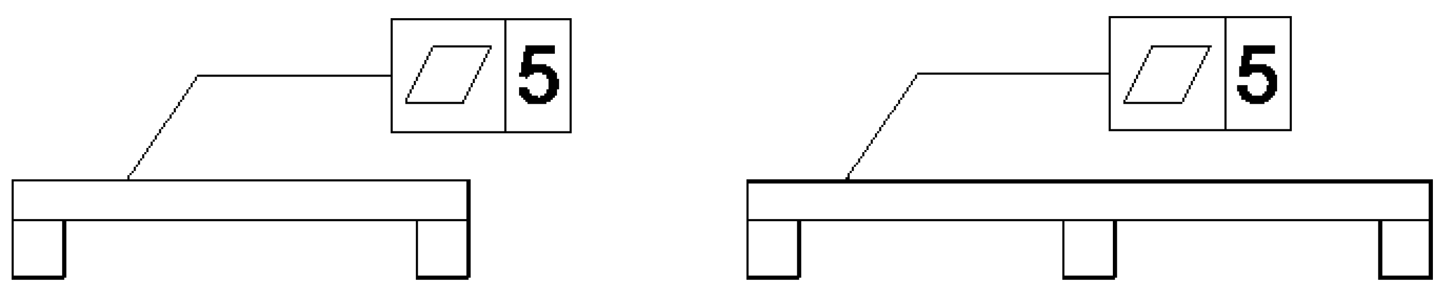
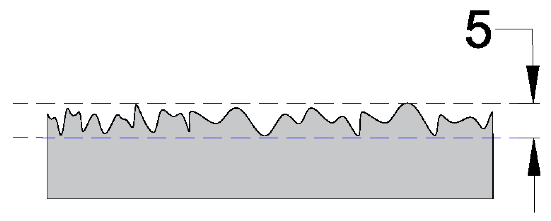
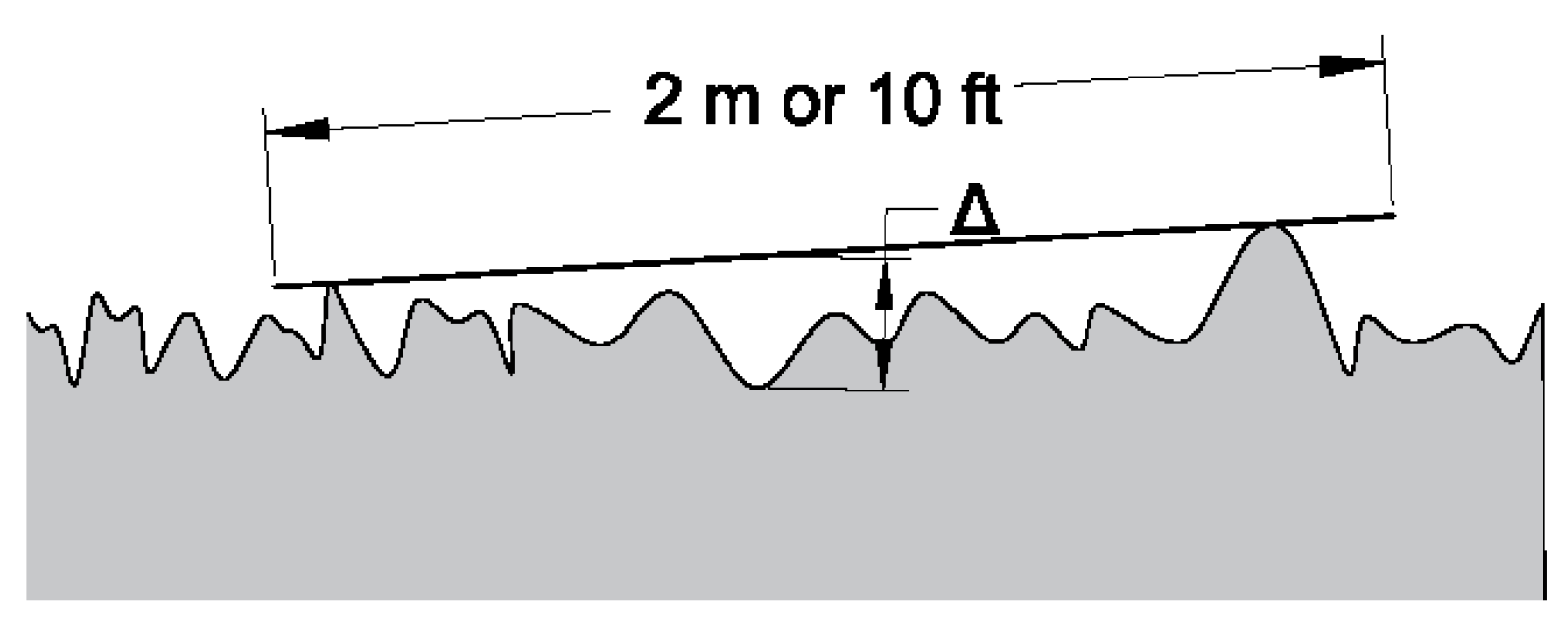
Flatness
4.1.2. Orientation Tolerances
Parallelism (Surface)
Perpendicularity
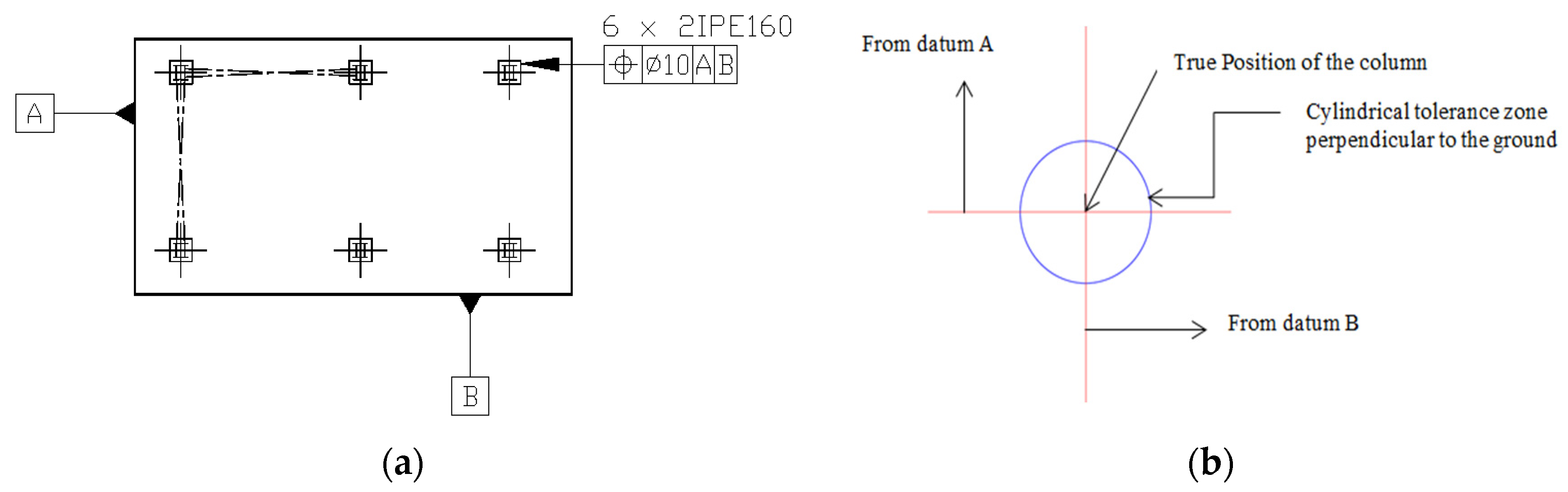
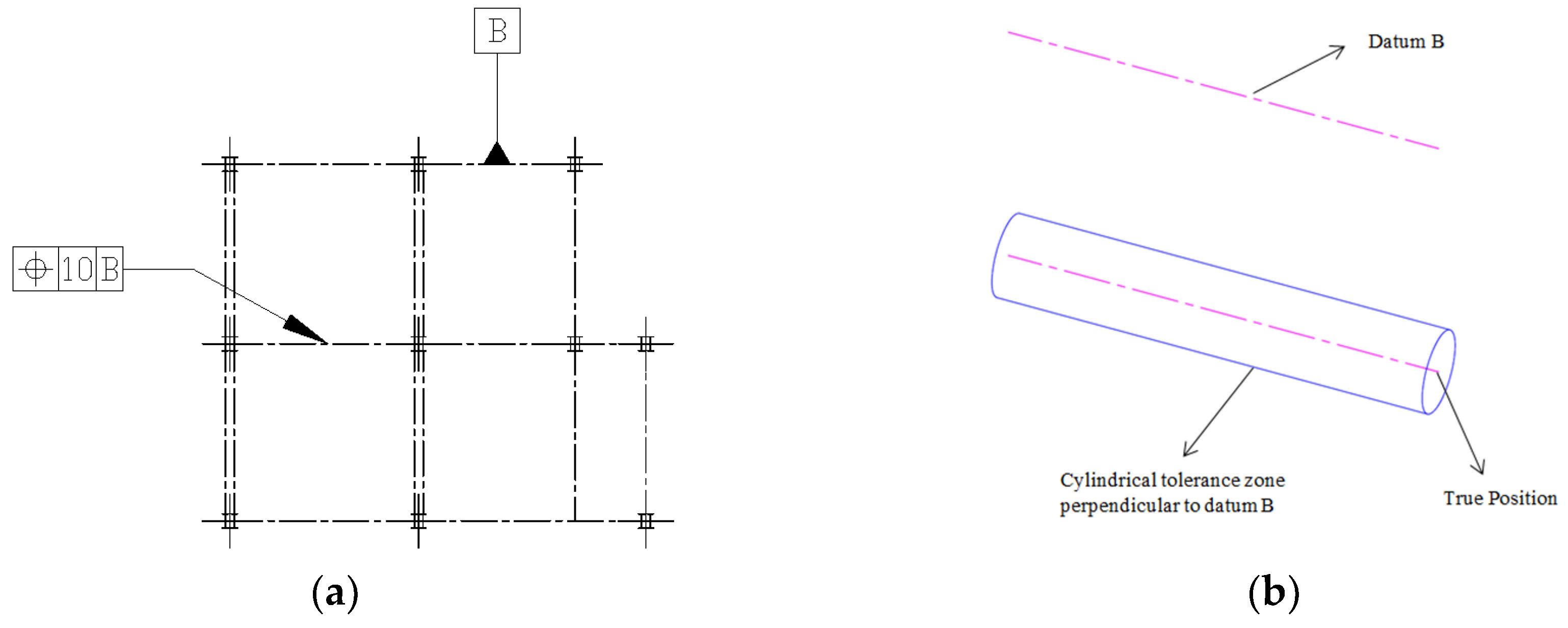
4.1.3. Location Tolerances
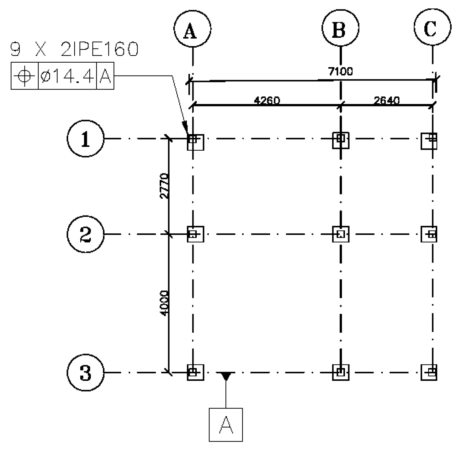
Tolerance of Position (TOP)
4.2. Discrepancies between GD&TIC Rules and Some of the Commonly Used American and British Reference Documents
4.2.1. Shape of the Tolerance Zone for the Flatness Control
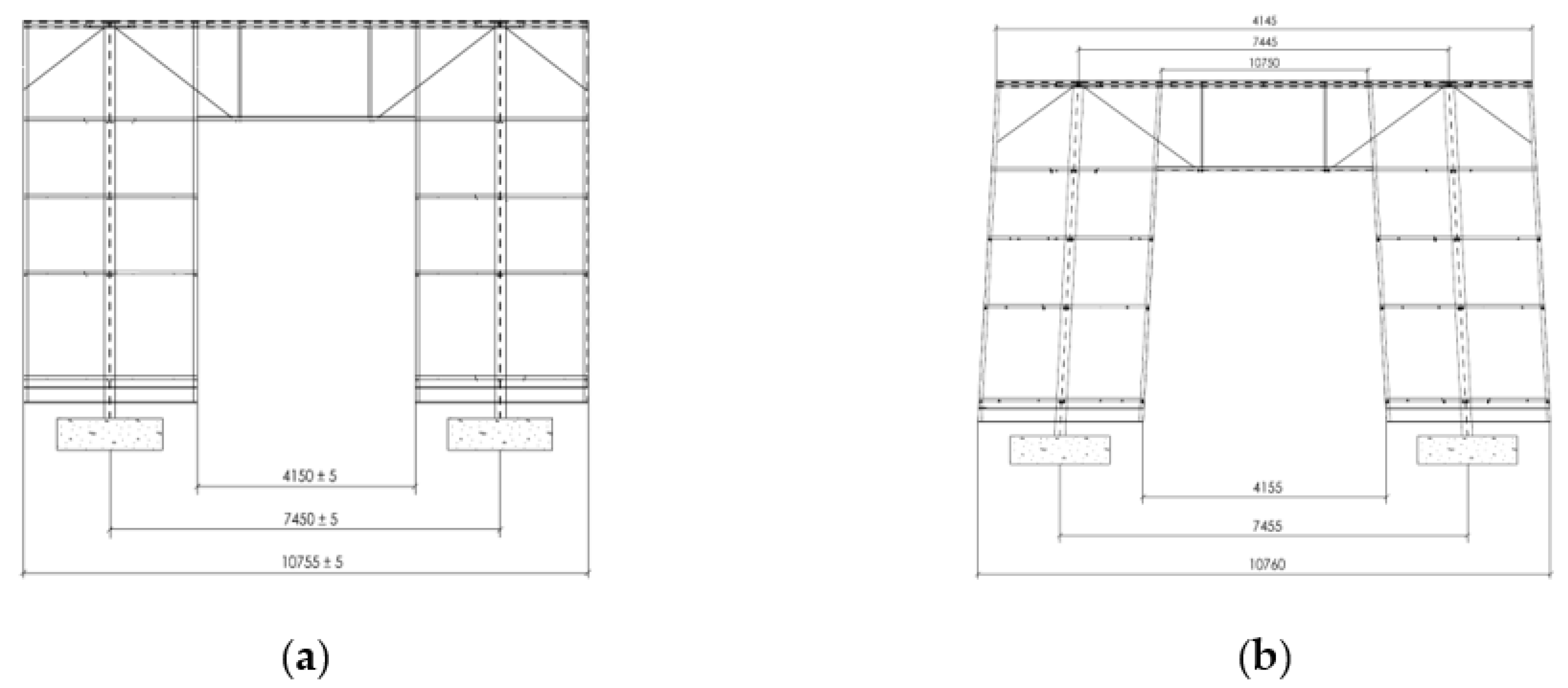
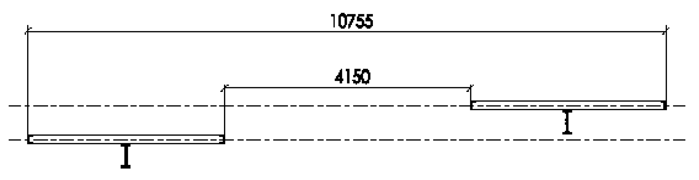
4.2.2. Shape of the Tolerance Zone for the TOP Control
4.3. Evaluation of GD&TIC
4.3.1. Efficacy
4.3.2. Practicality
4.3.3. Acceptability
4.3.4. Efficiency
4.3.5. Applicability
5. Discussion
6. Conclusions
Author Contributions
Funding
Conflicts of Interest
Appendix A. Summary of Identified Tolerance Problems in Case A and Case B.

| No. | Tolerance Problem | Description | Illustration |
|---|---|---|---|
| Case A | |||
| 1 | Flatness of concrete slab | The deflection calculation in this project was based on slab poured to the constant thickness specified, and no account had been taken for any additional weight as a result of the deflection of the supporting structure. However, more concrete was poured to level the concrete slab and achieve the intended flatness tolerance (±5 mm) to a certain extent. Making the slab thicker overloaded the ceiling, and this eventually caused more deflection (30 mm more than the specified tolerance). As a result, the intended flatness could not be achieved. An excessive gap was observed between the concrete slab and recessed skirting. This tolerance problem (the excessive deflection of the concrete slab and the subsequent gap between the slab and recessed skirting) occurred because of the lack of communication between the structural designer, the architect, and the concrete contractor regarding the anticipated deflection and required flatness tolerances. |  |
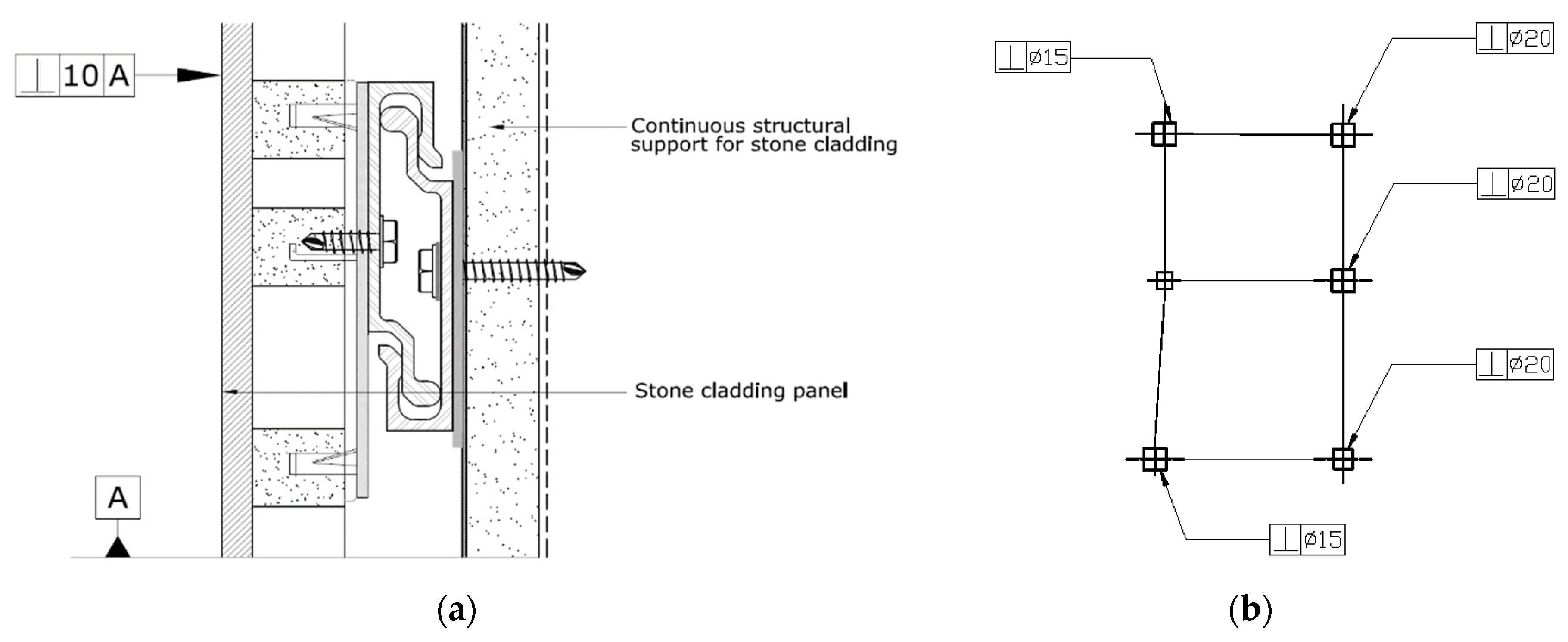
| 2 | Perpendicularity of columns and stone panels of the cladding system | The cladding contractor developed a design in which the offset from the steelwork to the face of the stone panels was 272 mm. In that case, the cladding system could absorb 32 mm of deviations due to the inclination of steel columns and stone panels. The architect later increased the offset to 290 mm. This was to accommodate the installation between the steelwork and cladding. Given that the distance between the steelwork and cladding system increased, the brackets of the cladding system could only absorb 15 mm deviations. As the stone panels were being installed, the steel columns and, subsequently, the stone panels started to lean into the building up to 30 mm at the roof level. This problem occurred due to the lack of communication between the structural designer, the architect, and the cladding contractor about the anticipated perpendicularity variations of columns and the required perpendicularity tolerance of columns and stone panels. |  |
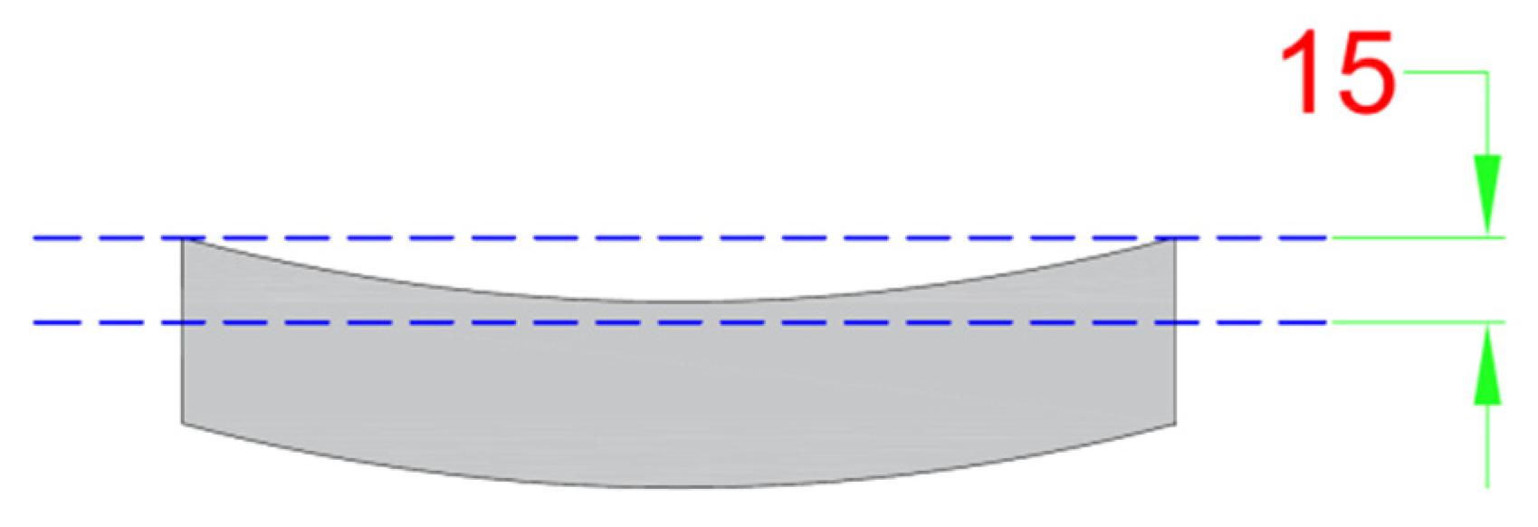
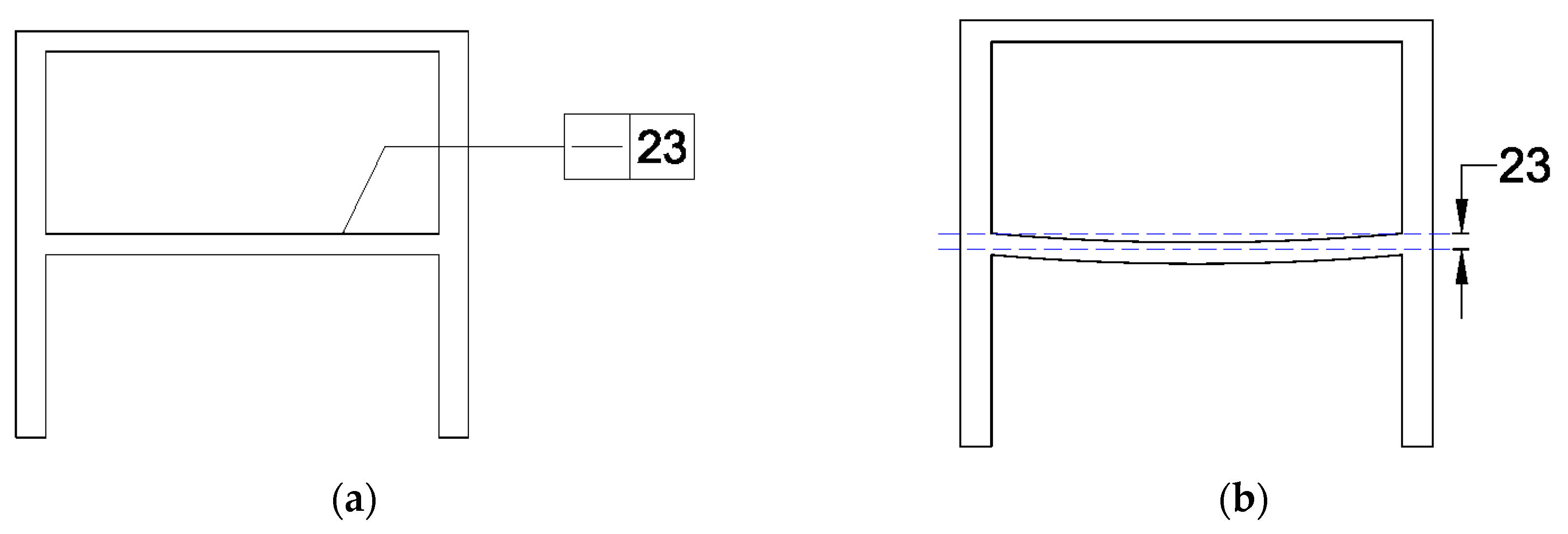
| 3 | Straightness of beams | When the dead load, due to the cladding, was applied on the steel frame, the stone panels started to sag. There was a noticeable gap between the channel and the stone panels in some areas, and the gap was not consistent all the way through. This problem (the excessive deflection of steel beams and the subsequent gap in the cladding) was as a result of the lack of communication of the straightness tolerances of the beams between the structural engineer, the architect, and the cladding contractor. |  |
| Case B | |||
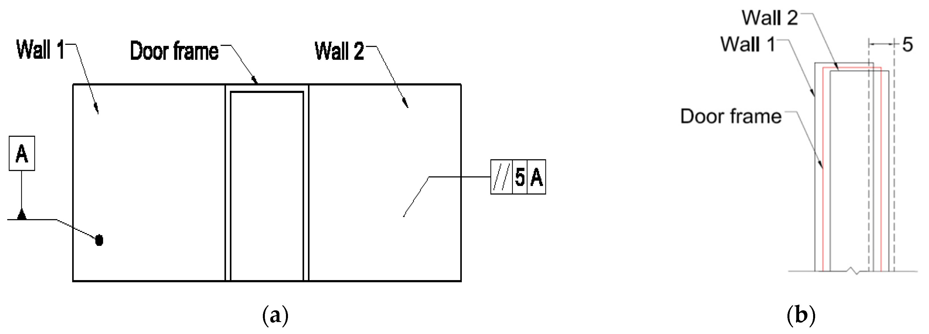
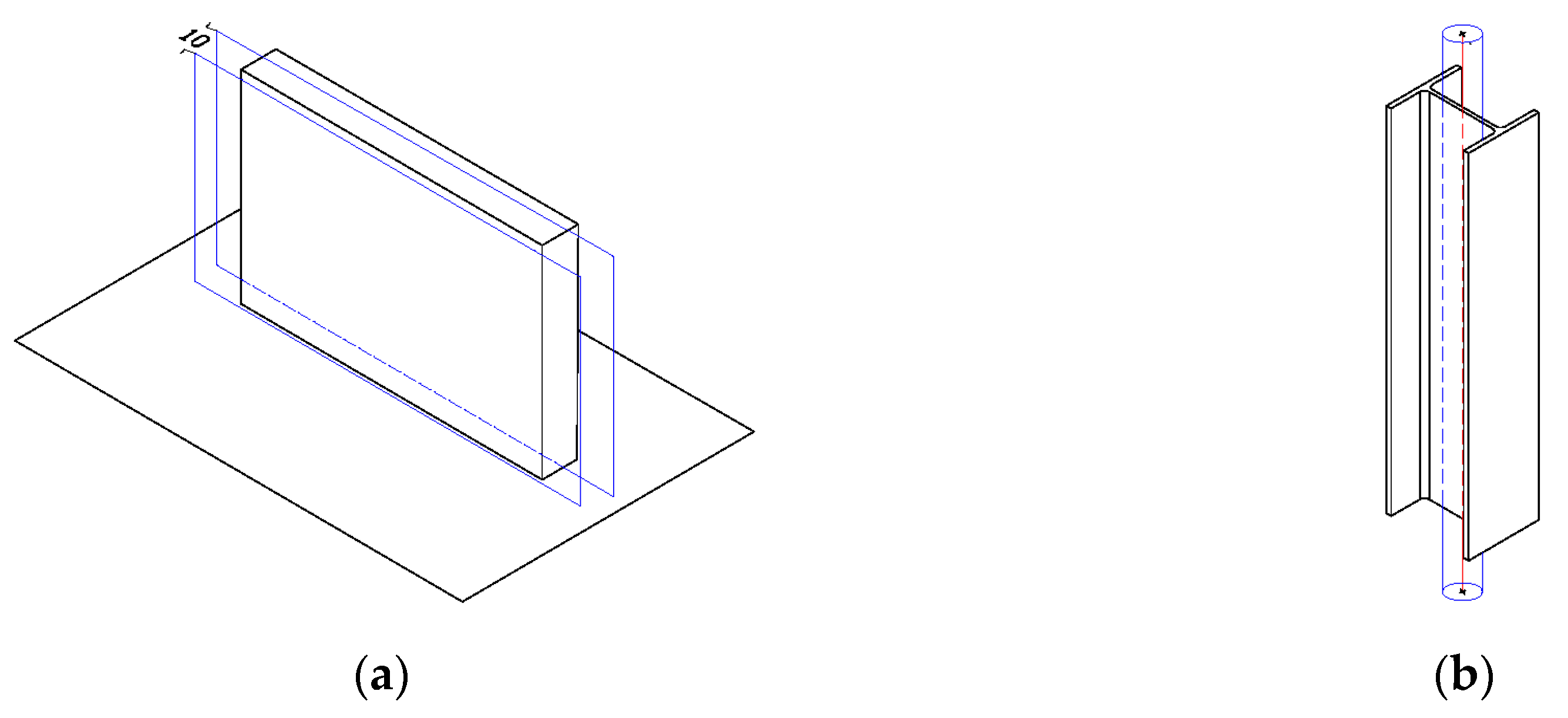
| 4 | Parallelism of the doorways | Columns, parallel flange channels (PFCs), and cladding rails were misaligned for 30–40 mm, so it was not possible to fit the roller shutter doors without the adjustment of the columns and PFCs. This problem occurred because no information could be found to indicate that the parallelism of stanchions was essential to ensure that electrically operated shutter doors would fit in the doorways. |  |
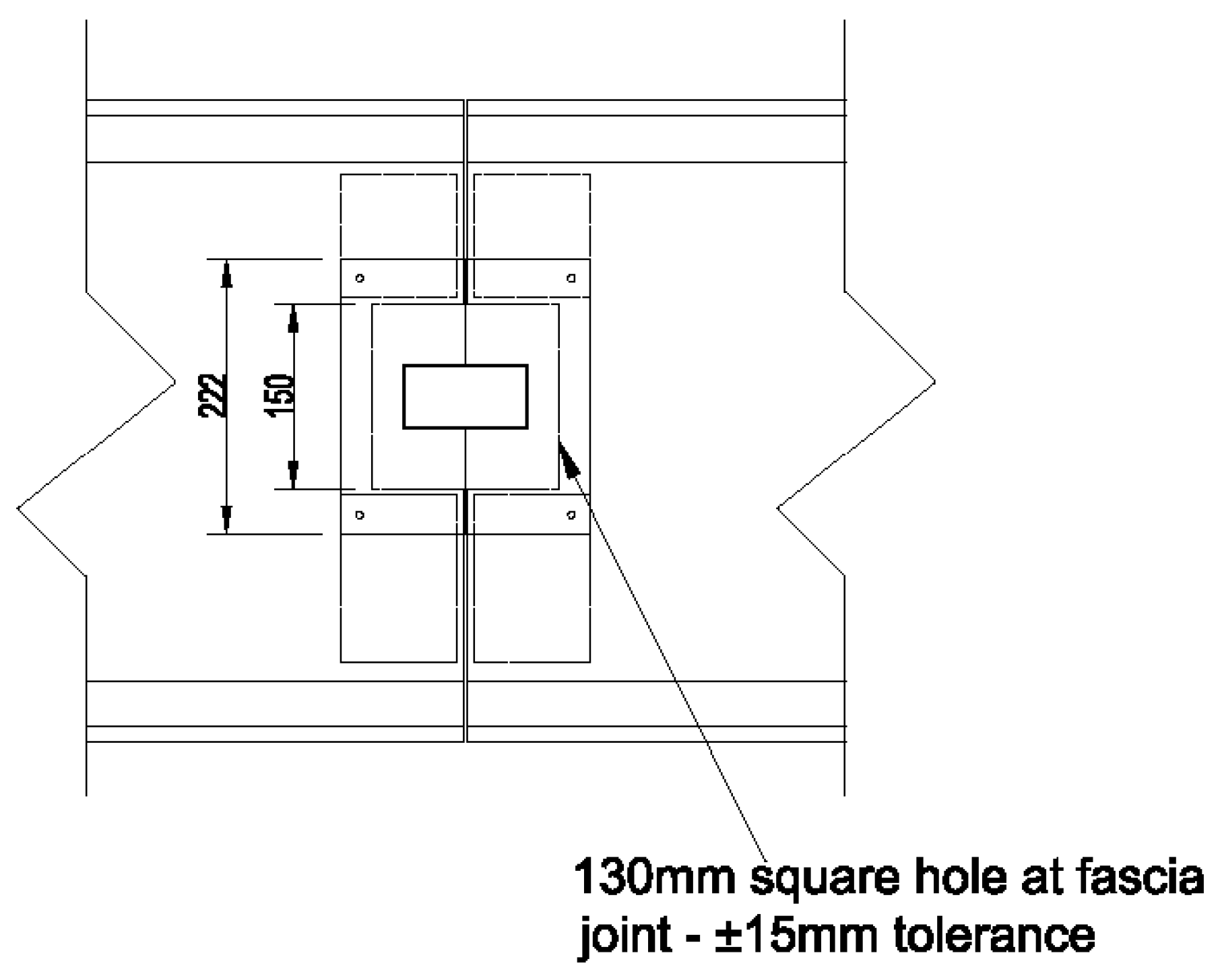
| 5 | Position of purlins on the roof | The purlins on the roof that support the cladding panels were out of the correct positions for 20 mm. As a result, there were no fixing points for the panels. This problem occurred due to the lack of communication between the steel and cladding contractors about the required position tolerance of purlins. |  |
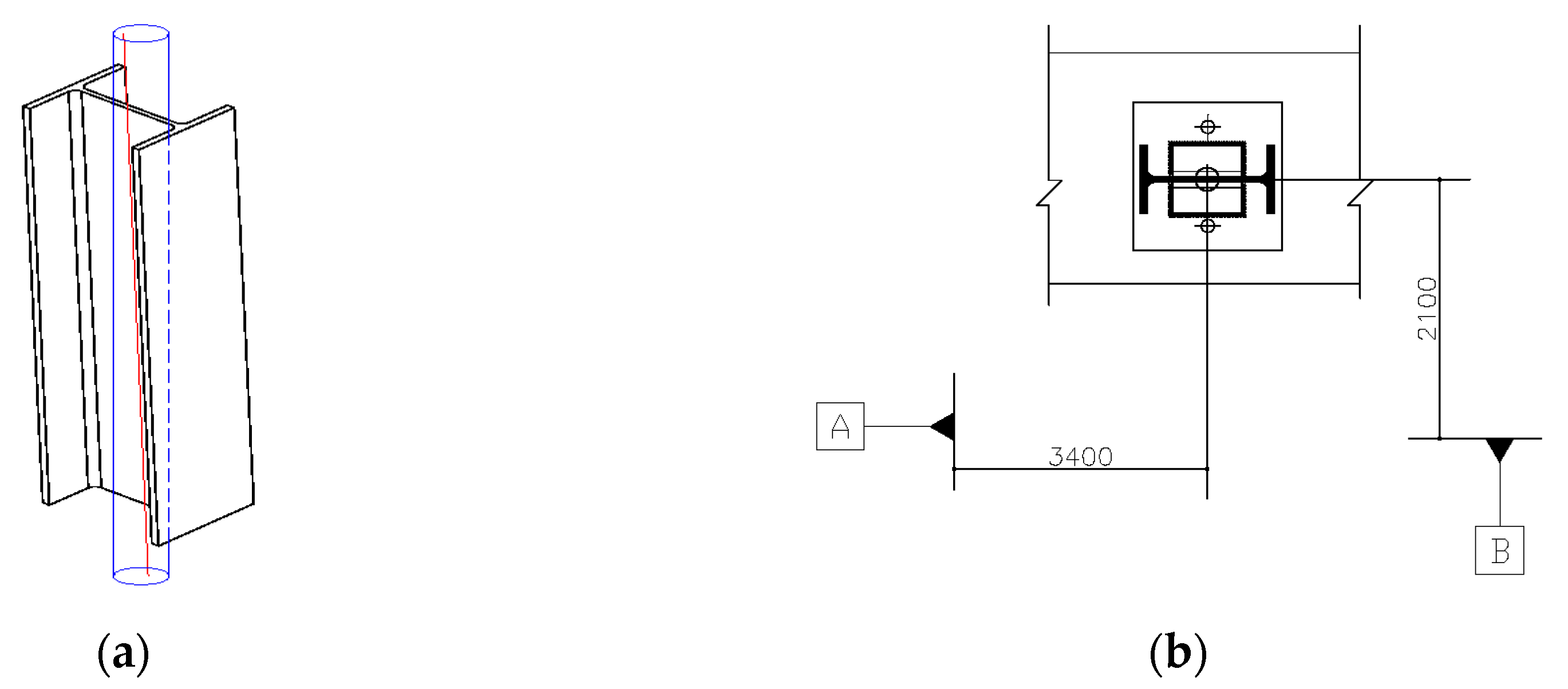
| 6 | Position of columns | The building was erected in two sides; hence, there was an interface between these two sides of the structure. It turned out that most of the columns in the first side were out of the position between 10–15 mm towards the second side. As a result, the beam coming across the top and connecting two sides of the building could not be fitted. This problem occurred because the position tolerance of columns was not communicated to the steel contractor. |  |
References
- Talebi, S.; koskela, L.; Tzortzopoulos, P.; Kagioglou, M. Tolerance management in construction: A conceptual framework. Sustainability 2020, 12, 1039. [Google Scholar] [CrossRef] [Green Version]
- Rausch, C.; Nahangi, M.; Haas, C.; Liang, W. Monte Carlo simulation for tolerance analysis in prefabrication and offsite construction. Autom. Constr. 2019, 103, 300–314. [Google Scholar] [CrossRef]
- Forcada, N.; Macarulla, M.; Gangolells, M.; Casals, M. Handover defects: Comparison of construction and post-handover housing defects. Build. Res. Inf. 2016, 44, 279–288. [Google Scholar] [CrossRef] [Green Version]
- Milberg, C.T.; Tommelein, I.D. Methods for managing tolerance compatibility: Windows in cast-in-place concrete. J. Constr. Eng. Manag. 2019, 146, 04019105. [Google Scholar] [CrossRef]
- Talebi, S. Improvement of Dimensional Tolerance Management in Construction. Ph.D. Thesis, University of Huddersfield, Huddersfield, UK, 2019. Available online: http://eprints.hud.ac.uk/id/eprint/35070/ (accessed on 30 January 2020).
- Liu, C.; Shirowzhan, S.; Sepasgozar, S.M.; Kaboli, A. Evaluation of classical operators and fuzzy logic algorithms for edge detection of panels at exterior cladding of buildings. Buildings 2019, 9, 40. [Google Scholar] [CrossRef] [Green Version]
- Krogstie, L.; Walter, M.S.; Wartzack, S.; Martinsen, K. Towards a more comprehensive understanding of tolerance engineering research importance. Proc CIRP 2015, 27, 29–34. [Google Scholar] [CrossRef] [Green Version]
- Savoini, J.-J.; Lafhaj, Z. Considering functional dimensioning in architectural design. Front. Archit. Res. 2017, 6, 89–95. [Google Scholar] [CrossRef]
- Jingmond, M.; Ågren, R. Unravelling causes of defects in construction. Constr. Innov. 2015, 15, 198–218. [Google Scholar] [CrossRef]
- Davison, B.; Owens, G.W. Steel Designers’ Manual, 6th ed.; Blackwell Science, Ltd.: Chennai, India, 2012; ISBN 9781405189408. [Google Scholar]
- Landin, A. Demands on the tolerances when industrialising the construction sector. In New Perspective in Industrialisation in Construction; Girmscheid, G., Scheublin, F., Eds.; International Council for Research and Innovation in Building and Construction: Zurich, Switzerland, 2010; pp. 197–205. ISBN 9873906800. [Google Scholar]
- Milberg, C.; Tommelein, I. Role of tolerances and process capability data in product and process design integration. In Proceedings of the Construction Research Congress, Honolulu, HI, USA, 19–21 March 2003. [Google Scholar]
- Rausch, C.; Nahangi, M.; Haas, C.; West, J. Kinematics chain based dimensional variation analysis of construction assemblies using building information models and 3D point clouds. Autom. Constr. 2017, 75, 33–44. [Google Scholar] [CrossRef]
- Gibb, A.G. Off-Site Fabrication: Prefabrication, Pre-Assembly and Modularisation; Whittles Publishing Scotland: Dunbeath, UK, 1999; ISBN 0470378360. [Google Scholar]
- American Concrete Institute. Guide for Tolerance Compatibility in Concrete Construction (ACI 117.1R-14); American Concrete Institute: Farmington Hills, MI, USA, 2014; Available online: https://www.concrete.org/store/productdetail.aspx?ItemID=117114&Language=English&Units=US_AND_METRIC (accessed on 25 March 2020).
- Rotimi, F.E.; Tookey, J.; Rotimi, J.O. Evaluating defect reporting in new residential buildings in New Zealand. Buildings 2015, 5, 39–55. [Google Scholar] [CrossRef]
- Krulikowski, A. Fundamentals of Geometric Dimensioning and Tolerancing, 3rd ed.; Cengage Learning: New York, NY, USA, 2012; ISBN 1285401972. [Google Scholar]
- Pathak, V.K.; Singh, A.K.; Sivadasan, M.; Singh, N. Framework for automated GD&T inspection using 3D scanner. J. Mech. Eng. Sci. 2018, 99, 197–205. [Google Scholar] [CrossRef]
- The American Society of Mechanical Engineers. Dimensioning and Tolerancing; The American Society of Mechanical Engineers: New York, NY, USA, 2009. [Google Scholar]
- Milberg, C. Application of Tolerance Management to Civil Systems. Ph.D. Thesis, University of California, Berkeley, CA, USA, 2006. Available online: http://citeseerx.ist.psu.edu/viewdoc/download?doi=10.1.1.308.5119&rep=rep1&type=pdf (accessed on 30 January 2020).
- Singh, P.; Jain, P.; Jain, S. Important issues in tolerance design of mechanical assemblies. Part 1: Tolerance analysis. Proc. Inst. Mech. Eng. Part B J. Eng. Manuf. 2009, 223, 1225–1247. [Google Scholar] [CrossRef]
- Gibb, A.G.F.; Pavitt, T.C. Interface management within construction: In particular, building facade. J. Constr. Eng. Manag. 2003, 129, 8–15. [Google Scholar] [CrossRef]
- Hayes, R.L. The Architect’s Handbook of Professional Practice, 15th ed.; John Wiley & Sons, Inc.: Hoboken, NJ, USA, 2014; ISBN 9781118174593. [Google Scholar]
- Ballast, D.K. Handbook of Construction Tolerances, 2nd ed.; John Wiley & Sons, Inc.: Hoboken, NJ, USA, 2007; ISBN 9781118260227. [Google Scholar]
- British Standards Institution. Design of Joints and Jointing in Building Construction: Guide; British Standards Institution: London, UK, 2013. [Google Scholar]
- British Standards Institution. Construction Drawings: Indication of Limit Deviations; British Standards Institution: London, UK, 1999. [Google Scholar]
- Singh, P.; Jain, P.; Jain, S. Important issues in tolerance design of mechanical assemblies. Part 2: Tolerance synthesis. Proc. Inst. Mech. Eng. Part B J. Eng. Manuf. 2009, 223, 1249–1287. [Google Scholar] [CrossRef]
- Fischer, B.R. Mechanical Tolerance Stackup and Analysis; CRC Press: Boca Raton, FL, USA, 2011; ISBN 1439815739. [Google Scholar]
- International Organisation for Standardization. Quality Management Systems: Requirements (BS EN ISO 9001:2015); ISO: London, UK, 2015. [Google Scholar]
- Construction Industry Institute. CII Best Practices Guide: Improving Project Performance; CII: Austin, TX, USA, 2012. [Google Scholar]
- Shahtaheri, Y.; Rausch, C.; West, J.; Haas, C.; Nahangi, M. Managing risk in modular construction using dimensional and geometric tolerance strategies. Autom. Constr. 2017, 83. [Google Scholar] [CrossRef]
- American Institute of Steel Construction. Code of Standard Practice for Structural Steel Buildings and Bridges (AISC 303-05); AISC: Chicago, IL, USA, 2005. [Google Scholar]
- British Standards Institution. Guide to Accuracy in Building; British Standards Institution: London, UK, 1990. [Google Scholar]
- British Constructional Steelwork Association. National Structural Steelwork Specification for Building Construction; British Constructional Steelwork Association: London, UK, 2010. [Google Scholar]
- British Standards Institution. Tolerances for Building: Recommendations for Basic Principles for Evaluation and Specification; British Standards Institution: London, UK, 1988. [Google Scholar]
- American Concrete Institute. Specification for Tolerances for Concrete Construction and Materials; American Concrete Institute: Farmington Hills, MI, USA, 2010; Available online: https://www.concrete.org/portals/0/files/pdf/previews/117-10web.pdf (accessed on 15 March 2020).
- British Standards Institution. Execution of Concrete Structures; British Standards Institution: London, UK, 2009. [Google Scholar]
- Love, P.E.D.; Edwards, D.J.; Irani, Z.; Walker, D.H.T. Project pathogens: The anatomy of omission errors in construction and resource engineering project. IEEE Trans. Eng. Manag. 2009, 56, 425–435. [Google Scholar] [CrossRef]
- Arashpour, M.; Heidarpour, A.; Akbar Nezhad, A.; Hosseinifard, Z.; Chileshe, N.; Hosseini, R. Performance-based control of variability and tolerance in off-site manufacture and assembly: Optimization of penalty on poor production quality. Constr. Manag. Econ. 2019, 1–13. [Google Scholar] [CrossRef]
- Price, C.; Goodier, C.I.; Fouchal, F.; Fraser, N. The Role of Standards in Offsite Construction: A Review of Existing Practice and Future Need; British Standards Institute: London, UK, 2019. [Google Scholar]
- Puri, N.; Valero, E.; Turkan, Y.; Bosché, F. Assessment of compliance of dimensional tolerances in concrete slabs using TLS data and the 2D continuous wavelet transform. Autom. Constr. 2018, 94, 62–72. [Google Scholar] [CrossRef]
- Valero, E.; Forster, A.; Bosché, F.; Hyslop, E.; Wilson, L.; Turmel, A. Automated defect detection and classification in ashlar masonry walls using machine learning. Autom. Constr. 2019, 106, 102846. [Google Scholar] [CrossRef]
- Sacks, R.; Ma, L.; Yosef, R.; Borrmann, A.; Daum, S.; Kattel, U. Semantic enrichment for building information modeling: Procedure for compiling inference rules and operators for complex geometry. J. Comput. Civ. Eng. 2017, 31. [Google Scholar] [CrossRef]
- Talebi, S.; Tzortzopoulos, P.; Koskela, L.; Poshdar, M.; Tommelein, I.D.; Tezel, A.; Antunes, R. A vision for the future of the computer-aided tolerance management in construction based on the lessons learned from manufacturing. In Proceedings of the CIB World Building Congress, Hong Kong, China, 17–21 June 2019. [Google Scholar]
- Puncochar, D.E.; Evans, K. Interpretation of Geometric Dimensioning and Tolerancing, 3rd ed.; Industrial Press: New York, NY, USA, 2011; ISBN 978-0-8311-3421-1. [Google Scholar]
- Henzold, G. Geometrical Dimensioning and Tolerancing for Design, Manufacturing and Inspection: A Handbook for Geometrical Product Specification Using ISO and ASME Standards, 2nd ed.; Butterworth-Heinemann: Oxford, UK, 2006; ISBN 0750667389. [Google Scholar]
- Miller, V. CAD Software. In Handbook of Design, Manufacturing and Automation; Dorf, R.C., Kusiak, A., Eds.; John Wiley & Sons, Inc.: New York, NY, USA, 1994; ISBN 9780470172452. [Google Scholar]
- Haghighi, P.; Mohan, P.; Kalish, N.; Vemulapalli, P.; Shah, J.J.; Davidson, J.K. Toward automatic tolerancing of mechanical assemblies: First-order GD&T schema development and tolerance allocation. J. Comput. Inf. Sci. Eng. 2015, 15. [Google Scholar] [CrossRef]
- Roy, U.; Liu, C.; Woo, T. Review of dimensioning and tolerancing: Representation and processing. Comput. Aided Des. 1991, 23, 466–483. [Google Scholar] [CrossRef] [Green Version]
- Milberg, C.; Tommelein, I.D. Tolerance and constructability of soldier piles in slurry walls. J. Perform. Constr. Facil. 2009, 24, 120–127. [Google Scholar] [CrossRef]
- Hevner, A.; March, S.T.; Park, J.; Ram, S. Design science in information systems research. Manag. Inf. Syst. 2004, 28, 75–105. [Google Scholar] [CrossRef] [Green Version]
- Van Aken, J. Management research as a design science: Articulating the research products of mode 2 knowledge production in management. Br. J. Manag. 2005, 16, 19–36. [Google Scholar] [CrossRef]
- Walls, J.G.; Widmeyer, G.R.; El Sawy, O.A. Building an information system design theory for vigilant EIS. Inf. Syst. Res. 1992, 3, 36–59. [Google Scholar] [CrossRef]
- Hevner, A.; Chatterjee, S. Design Research in Information Systems: Theory and Practice; Springer: New York, NY, USA, 2010; ISBN 1441956530. [Google Scholar]
- Koskela, L. Which kind of science is construction management? In Proceedings of the 16th Annual Conference of the International Group for Lean Construction, Manchester, UK, 16–18 July 2008; pp. 51–60. [Google Scholar]
- Jordan-Palomar, I.; Tzortzopoulos, P.; García-Valldecabres, J.; Pellicer, E. Protocol to manage heritage-building interventions using heritage building information modelling (HBIM). Sustainability 2018, 10, 908. [Google Scholar] [CrossRef] [Green Version]
- Voordijk, H. Construction management and economics: The epistemology of a multidisciplinary design science. Constr. Manag. Econ. 2009, 27, 713–720. [Google Scholar] [CrossRef]
- Schimanski, C.P.; Pasetti Monizza, G.; Marcher, C.; Matt, D.T. Pushing digital automation of configure-to-order services in small and medium enterprises of the construction equipment industry: A design science research approach. Appl. Sci. 2019, 9, 3780. [Google Scholar] [CrossRef] [Green Version]
- Van Aken, J.E.; Berends, H.; van der Bij, H. Problem Solving in Organizations: A Methodological Handbook for Business, 2nd ed.; Cambridge University Press: Cambridge, UK, 2012; ISBN 1280850213. [Google Scholar]
- Gregor, S.; Hevner, A.R. Positioning and presenting design science research for maximum impact. MIS. Q. 2013, 37, 337–356. [Google Scholar] [CrossRef]
- Dresch, A.; Lacerda, D.P.; Antunes, J.A.V., Jr. Design Science Research: A Method for Science and Technology Advancement; Springer: Porto Alegre, Brazil, 2015; ISBN 9783319356099. [Google Scholar]
- Ballast, D.K. Architect’s Handbook of Construction Detailing; John Wiley & Sons: Hoboken, NJ, USA, 2009; ISBN 0470381914. [Google Scholar]
- Talebi, S.; Koskela, L.; Shelbourn, M.; Tzortzopoulos, P. Critical review of tolerance management in construction. In Proceedings of the 24th Annual Conference of the International Group for Lean Construction, Boston, MA, USA, 20–22 July 2016. [Google Scholar]
- Kasanen, E.; Lukka, K.; Siitonen, A. The constructive approach in management accounting research. J. Manag. Account. Res. 1993, 5, 243–264. [Google Scholar]
- Alturki, A.; Gable, G.G.; Bandara, W. A Design Science Research roadmap. In Proceedings of the International Conference on Design Science Research in Information Systems, Berlin, Germany, 5–6 May 2011; pp. 107–123. [Google Scholar]
- Vaishnavi, V.K.; Kuechler, W. Design Science Research Methods and Patterns: Innovating Information and Communication Technology, 2nd ed.; CRC Press: Boca Raton, FL, USA, 2015; ISBN 1420059327. [Google Scholar]
- Lukka, K. The constructive research approach. In Case Study Research in Logistics; Ojala, L., Hilmola, O.-P., Eds.; Turku School of Economics and Business Administration: Turku, Finland, 2003; pp. 83–101. ISBN 9781615831463. [Google Scholar]
- Valdes, F.J. Manufacturing Compliance Analysis for Architectural Design: A Knowledge-Aided Feature-Based Modeling Framework. Ph.D. Thesis, Georgia Tech, Atlanta, GA, USA, 2016. Available online: http://hdl.handle.net/1853/54973 (accessed on 30 January 2020).
- Miles, M.B.; Huberman, A.M. Qualitative data analysis: An expanded sourcebook. Serv. Ind. J. 1995, 15, 366. [Google Scholar]
- Saunders, M.; Lewis, P.; Thornhill, A. Research Methods for Business Students, 7th ed.; Pearson Education: Harlow, UK, 2016; ISBN 9780273716860. [Google Scholar]
- Boddy, C.R. Sample size for qualitative research. Qual. Mark. Res. Int. J. 2016, 19, 426–432. [Google Scholar] [CrossRef]
- Brinkmann, S. Qualitative Interviewing: Understanding Qualitative Research; Oxford University Press: New York, NY, USA, 2013; ISBN 0199861390. [Google Scholar]
- Eisenhardt, K.M. Building theories from case study research. Acad. Manag. Rev. 1989, 14, 532–550. [Google Scholar] [CrossRef]
- Yin, R.K. Case Study Research: Design and Methods, 4th ed.; SAGE Publications: Southend Oaks, CA, USA, 2013; ISBN 978-1-4129-6099-1. [Google Scholar]
- Bruseberg, A.; McDonagh-Philp, D. Focus groups to support the industrial/product designer: A review based on current literature and designers’ feedback. Appl. Ergon. 2002, 33, 27–38. [Google Scholar] [CrossRef]
- Rooke, J.A.; Kagioglou, M. Criteria for evaluating research: The unique adequacy requirement of methods. Constr. Manag. Econ. 2007, 25, 979–987. [Google Scholar] [CrossRef]
- Lynch, M. Harold Garfinkel (29 October 1917–21 April 2011): A remembrance and reminder. Soc. Stud. Sci. 2011, 41, 927–942. [Google Scholar] [CrossRef]
- Rooke, J.A.; Rooke, C.N. From interpretation to action: Unique adequacy as a common standard for the evaluation of research in the built environment. In Ethnographic Research in the Construction Industry; Pink, S., Tutt, D., Dainty, A., Eds.; Routledge: New York, NY, USA, 2012; pp. 159–177. ISBN 0415603439. [Google Scholar]
- Garfinkel, H. Ethnomethodology’s Program: Working out Durkheim’s Aphorism; Rowman & Littlefield Publishers: Lanham, MD, USA, 2002; ISBN 0742578984. [Google Scholar]
- Morriss, L. Dirty secrets and being ‘strange’: Using ethnomethodology to move beyond familiarity. Qual. Res. 2016, 16, 526–540. [Google Scholar] [CrossRef] [Green Version]
- Garfinkel, H.; Rawls, A.; Lemert, C.C. Seeing Sociologically: The Routine Grounds of Social Action; Routledge: New York, NY, USA, 2015; ISBN 1317252276. [Google Scholar]
- Tremblay, M.C.; Hevner, A.R.; Berndt, D.J. Focus groups for artifact refinement and evaluation in design research. Cais 2010, 26, 599–618. [Google Scholar] [CrossRef] [Green Version]
- Kitzinger, J. Qualitative Research: Introducing focus groups. BMJ 1995, 311, 299–302. [Google Scholar] [CrossRef] [Green Version]
- Checkland, P. Soft systems methodology: A thirty year retrospective. Syst. Res. Behav. Sci. 2000, 17, S11–S58. [Google Scholar] [CrossRef]
- Tzortzopoulos, P. The Design and Implementation of Product Development Process Models in Construction Companies. Ph.D. Thesis, University of Salford, Salford, UK, 2004. Available online: http://usir.salford.ac.uk/id/eprint/26949/ (accessed on 15 February 2020).
- Khan, S.; Tzortzopoulos, P. A framework for evaluating an action research study on lean design management. In Proceedings of the 24th Annual Conference of the International Group for Lean Construction, Boston, MA, USA, 20–22 July 2016. [Google Scholar]
- Polini, W. Concurrent tolerance design. Res. Eng. Des. 2016, 27, 23–36. [Google Scholar] [CrossRef]
- Peng, H.; Peng, Z. Concurrent design and process tolerances determination in consideration of geometrical tolerances. J. Mech. Eng. Sci. 2019, 233, 6727–6740. [Google Scholar] [CrossRef]
- The American Society of Mechanical Engineers. Dimensioning and Tolerancing (Y14.5M); ASME: New York, NY, USA, 1994. [Google Scholar]
- Phua, F.T.; Rowlinson, S. Operationalizing culture in construction management research: A social identity perspective in the Hong Kong context. Constr. Manag. Econ. 2004, 22, 913–925. [Google Scholar] [CrossRef]
- Dantan, J.-Y.; Huang, Z.; Goka, E.; Homri, L.; Etienne, A.; Bonnet, N.; Rivette, M. Geometrical variations management for additive manufactured product. CIRP Ann. 2017, 66, 161–164. [Google Scholar] [CrossRef] [Green Version]
- Cogorno, G.R. Geometric Dimensioning and Tolerancing for Mechanical Design; Mac Graw-Hill: New York, NY, USA, 2006; ISBN 0071460705. [Google Scholar]
- Meadows, J.D. Geometric Dimensioning and Tolerancing: Applications and Techniques for Use in Design, Manufacturing, and Inspection; CRC Press: New York, NY, USA, 1995; ISBN 0824793099. [Google Scholar]
- Schenk, C.A.; Bergman, L.A. Response of continuous system with stochastically varying surface roughness to moving load. J. Eng. Mech. 2003, 129, 759–768. [Google Scholar] [CrossRef]
- Chiabert, P.; Lombardi, F.; Orlando, M. Benefits of geometric dimensioning and tolerancing. J. Mater. Process. Technol. 1998, 78, 29–35. [Google Scholar] [CrossRef]
- Das, P.; Chandran, R.; Samant, R.; Anand, S. Optimum part build orientation in additive manufacturing for minimizing part errors and support structures. Procedia Manuf. 2015, 1, 343–354. [Google Scholar] [CrossRef] [Green Version]
- Romero Subirón, F.; Rosado Castellano, P.; Bruscas Bellido, G.M.; Benavent Nácher, S. Feature-based framework for inspection process planning. Materials 2018, 11, 1504. [Google Scholar] [CrossRef] [Green Version]
- Zhang, H.-C. Advanced Tolerancing Techniques; John Wiley & Sons: New York, NY, USA, 1997; ISBN 0471145947. [Google Scholar]
- Schleich, B.; Wärmefjord, K.; Söderberg, R.; Wartzack, S. Geometrical variations management 4.0: Towards next generation geometry assurance. Procedia CIRP 2018, 75, 3–10. [Google Scholar] [CrossRef]
- Yan, Y.; Bohn, M.; Peters, S.; Heisel, U. Complementing and enhancing definitions of position tolerance for a real point based on ISO Geometrical Product Specifications (GPS). Manuf. Sci. Technol. 2018, 22, 107–110. [Google Scholar] [CrossRef]
- Qin, Y.; Lu, W.; Liu, X.; Huang, M.; Zhou, L.; Jiang, X. Description logic-based automatic generation of geometric tolerance zones. Int. J. Adv. Manuf. Technol. 2015, 79, 1221–1237. [Google Scholar] [CrossRef]
- Budinoff, H.; McMains, S. Prediction and visualization of achievable orientation tolerances for additive manufacturing. Procedia CIRP 2018, 75, 81–86. [Google Scholar] [CrossRef]
- Wahab, D.; Azman, A. Additive manufacturing for repair and restoration in remanufacturing: An overview from object design and systems perspectives. Processes 2019, 7, 802. [Google Scholar] [CrossRef] [Green Version]
- Stites, W.M.; Drake, P.J. Geometric Dimensioning and Tolerancing. In Dimensioning and Tolerancing Handbook; Drake, P.J., Ed.; McGraw-Hill: New York, NY, USA, 1999; ISBN 0070181314. [Google Scholar]
- British Standards Institution. Screeds, Bases and in Situ Floorings—Part 2: Concrete Bases and Cementitio us Levelling Screeds to Receive Floorings; Code of Practice (BS 8204-1:2003 +A1); British Standards Institution: London, UK, 2011. [Google Scholar]
- Concu, G.; Trulli, N. Concrete defects sizing by means of ultrasonic velocity maps. Buildings 2018, 8, 176. [Google Scholar] [CrossRef] [Green Version]
- British Standards Institution. Screeds, bases and in situ floorings. In Concrete Bases and Cementitious Levelling Screeds to Receive Floorings; Code of Practice; British Standards Institution: London, UK, 2009. [Google Scholar]
- American Concrete Institute. Guide for Concrete Floor and Slab Construction (ACI 302.1R-89); American Concrete Institute: Farmington Hills, MI, USA, 1989; Available online: http://dl.mycivil.ir/dozanani/ACI/ACI%20302.1R-04%20Guide%20for%20Concrete%20Floor%20and%20Slab%20Construction_MyCivil.ir.pdf (accessed on 14 March 2020).
- British Standards Institution. Execution of Steel Structures: General Rules and Rules for Buildings; British Standards Institution: London, UK, 1998. [Google Scholar]
- Sieber, I.; Yi, A.Y.; Gengenbach, U. Metrology Data-Based Simulation of Freeform Optics. Appl. Sci. 2018, 8, 2338. [Google Scholar] [CrossRef] [Green Version]
- British Standards Institution. Building Construction: Tolerances, Expression of Dimensional Accuracy, Principles and Terminology (BS ISO 1803); British Standards Institution: London, UK, 1997. [Google Scholar]
- Kagioglou, M.; Cooper, R.; Aouad, G.; Sexton, M. Rethinking construction: The generic design and construction process protocol. Eng. Constr. Archit. Manag. 2000, 7, 141–153. [Google Scholar] [CrossRef] [Green Version]
- Liker, J.K. The Toyota Way: 14 Management Principles from the World’s Greatest Manufacturer; McGraw-Hill: New York, NY, USA, 2004; ISBN 9797813770. [Google Scholar]


| Project | Type of Project | Development Stage |
|---|---|---|
| Case A | A circa 7500 m2 building | The installation of the building envelope and interior components |
| Case B | A circa 2.30 ha terraced warehouse/manufacturing building | Erection of structural frame |
| Case A | Case B |
|---|---|
| Role/position of interviewee | Role/position of interviewee |
| Project Director Design Manager Architect Site Engineer Quantity Surveyor Senior Quantity Surveyor | Project Director Senior Project Manager Site Manager Site Engineer |
| Project | Corresponding No. | Description |
|---|---|---|
| Case A | Tolerance Problem 1 | Flatness of concrete slabs |
| Case A | Tolerance Problem 2 | Perpendicularity of columns and cladding stone panels |
| Case A | Tolerance Problem 3 | Straightness of beams |
| Case B | Tolerance Problem 4 | Parallelism of doorways |
| Case B | Tolerance Problem 5 | Position of purlins on the roof |
| Case B | Tolerance Problem 6 | Position of columns |
| Criteria | Attributes | Corresponding Questions |
|---|---|---|
| Effectiveness | Acceptability | Does GD&TIC have the potential to be accepted by designers and contractors, and to be used in the AEC industry? |
| Efficacy | Is GD&TIC useful in the sense that it will lead to improved tolerancing in AEC? | |
| Efficiency | Does the time and cost needed to implement GD&TIC outweigh the costs saved as a result of eliminated reworks, delays and poor quality? | |
| Usefulness | Practicality | In terms of clarity and simplicity, is GD&TIC easy to implement? |
| Practicality | Could GD&TIC avoid the tolerance problems identified in Case A and Case B? |
| Type of Tolerance | Geometric Characteristics | Symbols | Tolerance Zone | Datum Required |
|---|---|---|---|---|
| Form: It establishes the shape of a surface. | Straightness: It represents how straight a surface is on along a line. |  | 2D Tolerance Zone: Two parallel lines | No |
| Flatness: It demonstrates the amount of deviation of flatness that a surface is allowed to have. |  | 3D Tolerance Zone: Two parallel planes, where the entire surface must lie. | No | |
| Orientation: It describes the relationship between features and datums at particular angles. | Perpendicularity (surface): limits the amount of variation allowed over a from being parallel to the datum plane. |  | 3D Tolerance Zone: Cylindrical boundary that is directly perpendicular to the datum plane | Optional |
| Parallelism: It limits the amount of variation allowed over an entire plane, from being parallel to the reference plane. |  | 2D or 3D Tolerance Zone: Two planes, that are parallel to the datum plane | Yes | |
| Location: It establishes the position of the feature relative to a datum. | Tolerance of Position (TOP): It determines the deviation of a feature’s axis from the Perfect position. |  | 3D Tolerance Zone: Cylindrical boundary where the central axis of a feature of size must lie, concerning the theoretically perfect location. | Yes |
| Type of Tolerance | Geometric Characteristics | Applications |
|---|---|---|
| Form | Straightness | To control the beams and columns that are prone to deformation. |
| Flatness | To control the flatness of floor surfaces. | |
| Orientation | Perpendicularity (surface) | To control components for which plumbness tolerances are a major concern. |
| Parallelism | To control surfaces that should maintain a constant distance. | |
| Location | Tolerance of Position (TOP) | To control (1) the location of features of size such as columns and beams and (2) the distance between those features of size |
© 2020 by the authors. Licensee MDPI, Basel, Switzerland. This article is an open access article distributed under the terms and conditions of the Creative Commons Attribution (CC BY) license (http://creativecommons.org/licenses/by/4.0/).
Share and Cite
Talebi, S.; Koskela, L.; Tzortzopoulos, P.; Kagioglou, M.; Krulikowski, A. Deploying Geometric Dimensioning and Tolerancing in Construction. Buildings 2020, 10, 62. https://doi.org/10.3390/buildings10040062
Talebi S, Koskela L, Tzortzopoulos P, Kagioglou M, Krulikowski A. Deploying Geometric Dimensioning and Tolerancing in Construction. Buildings. 2020; 10(4):62. https://doi.org/10.3390/buildings10040062
Chicago/Turabian StyleTalebi, Saeed, Lauri Koskela, Patricia Tzortzopoulos, Michail Kagioglou, and Alex Krulikowski. 2020. "Deploying Geometric Dimensioning and Tolerancing in Construction" Buildings 10, no. 4: 62. https://doi.org/10.3390/buildings10040062