An Anchoring Groove Technique to Enhance the Bond Behavior between Heat-Damaged Concrete and CFRP Composites


Abstract
:1. Introduction
2. Description of the Experimental Program
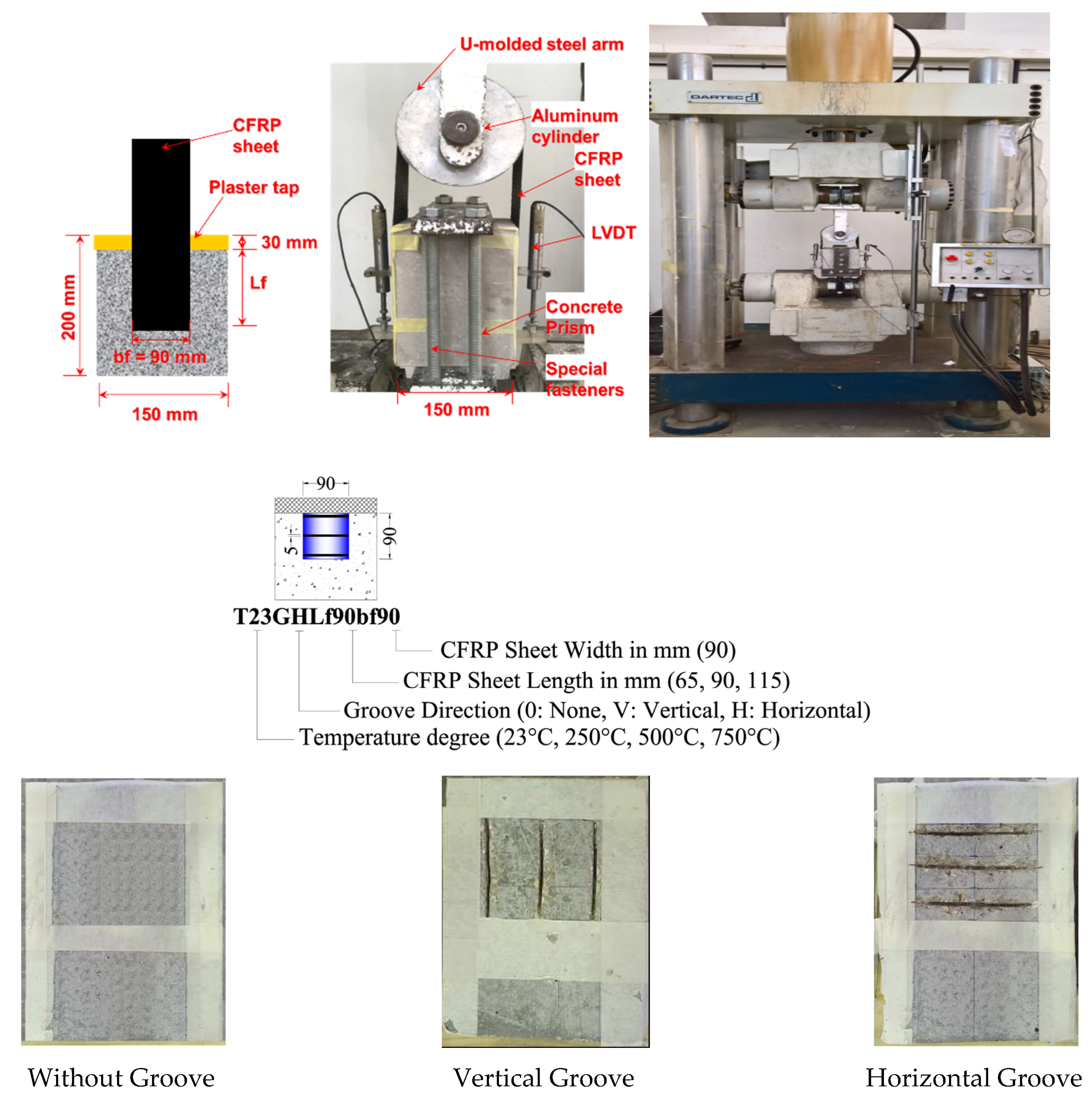
2.1. Test Specimens
2.2. The Properties of the Materials
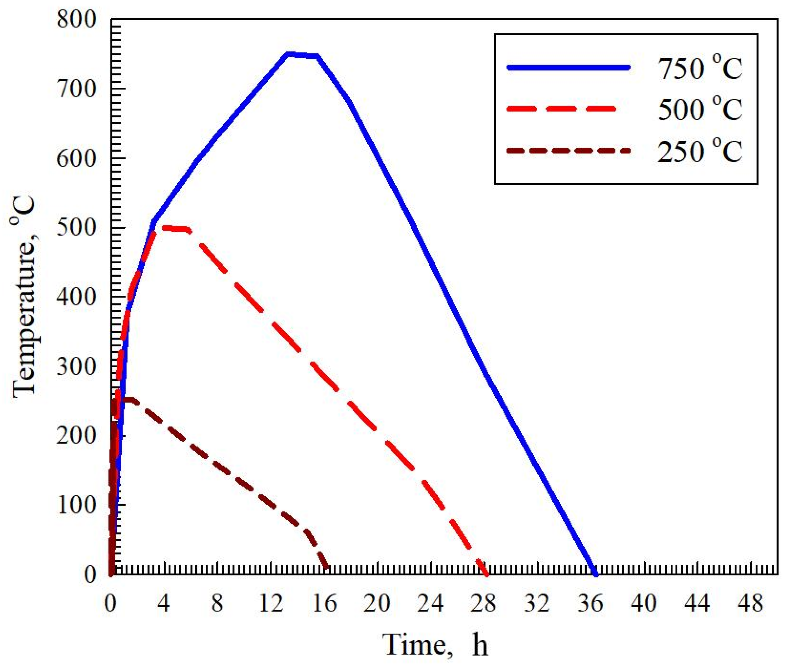
2.3. Heat Treatment Method
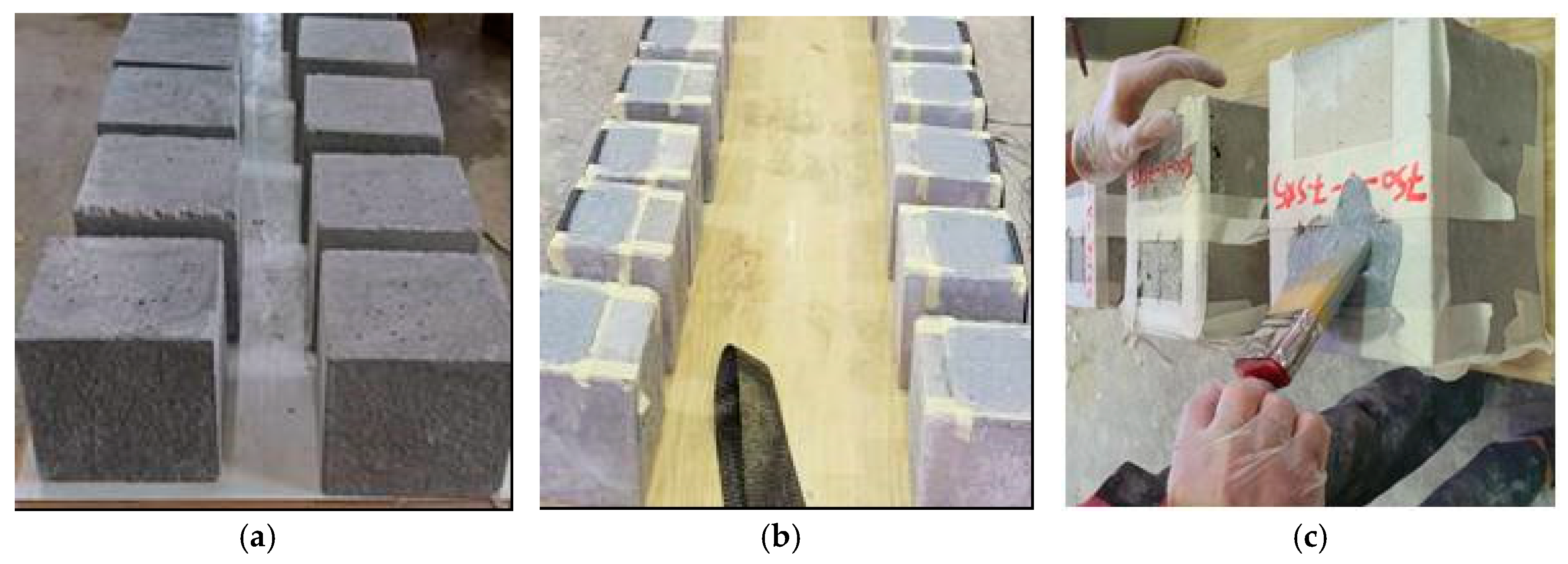
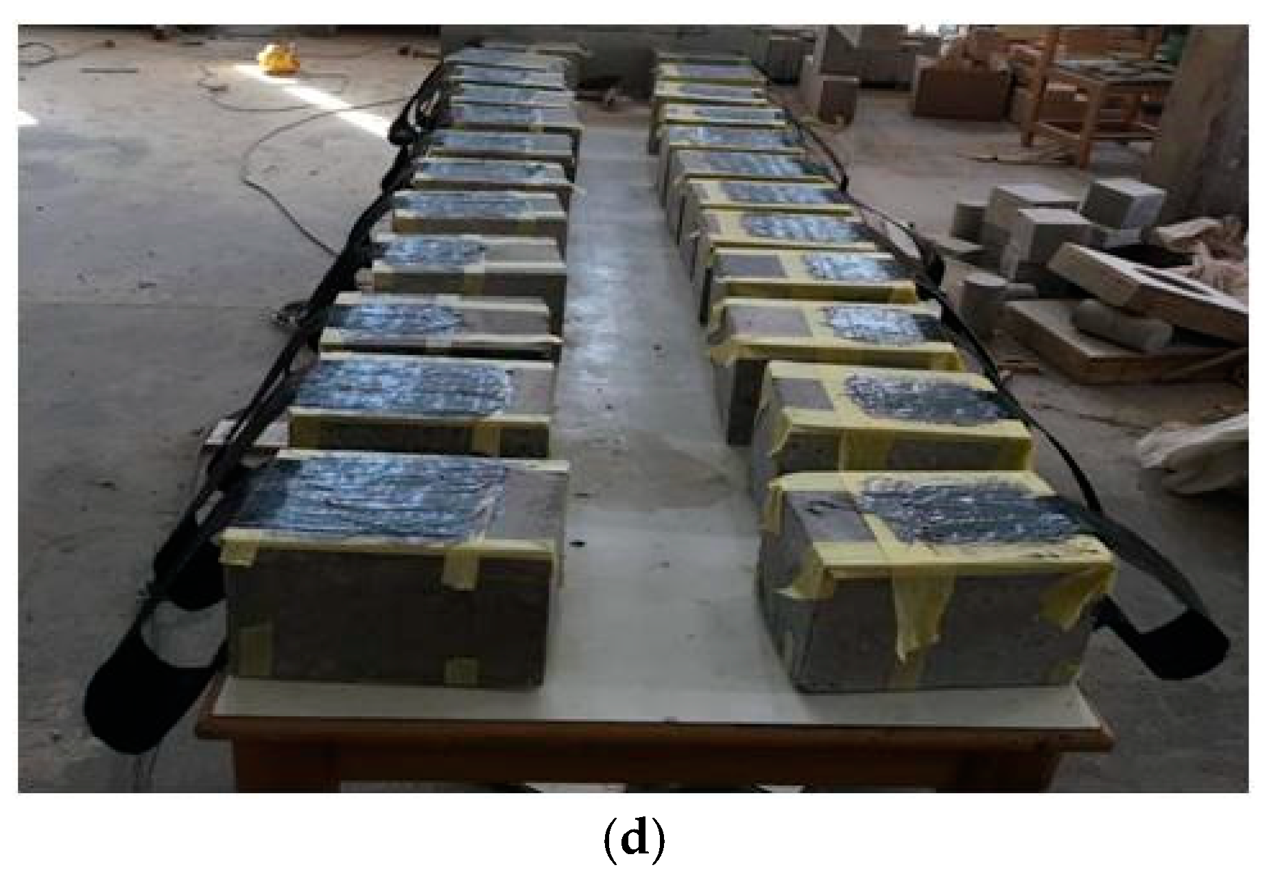
2.4. Preparation of Specimens
2.5. Test Procedure
3. Results and Discussion
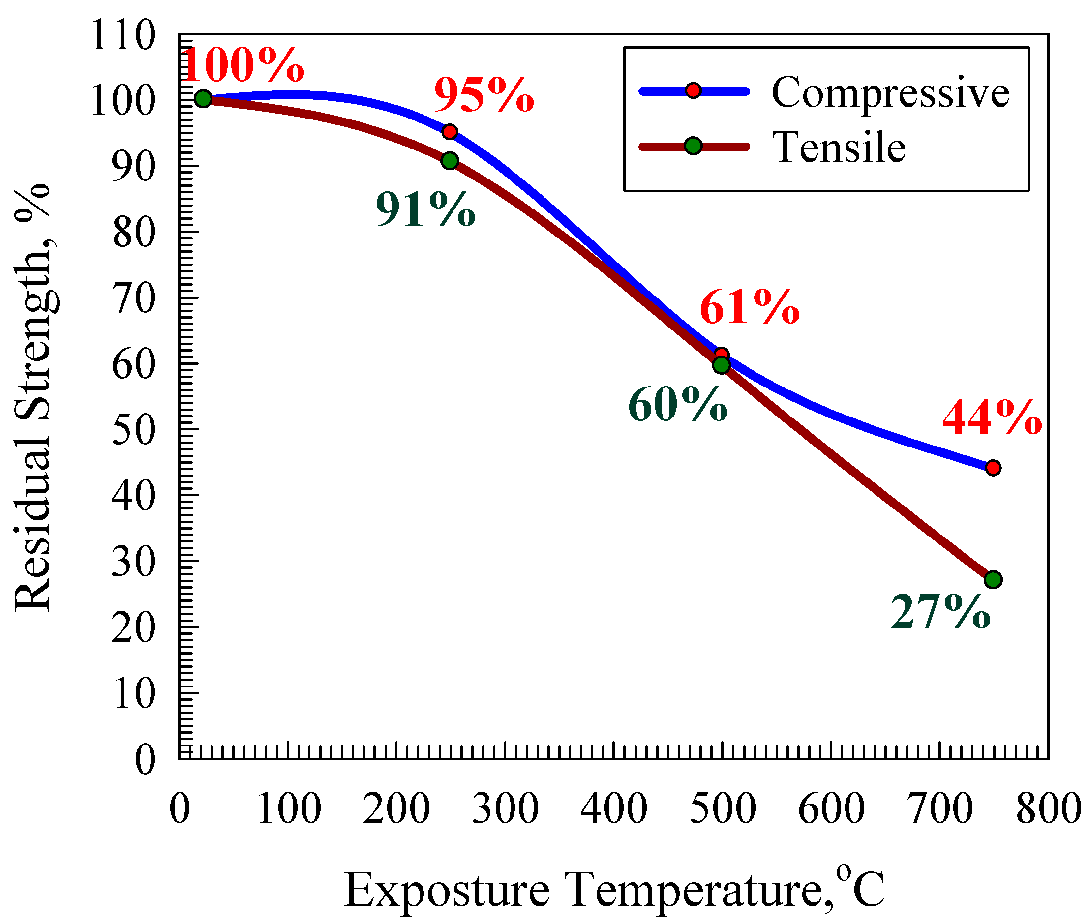
3.1. Effect of Elevated Temperatures on Strength Residuals
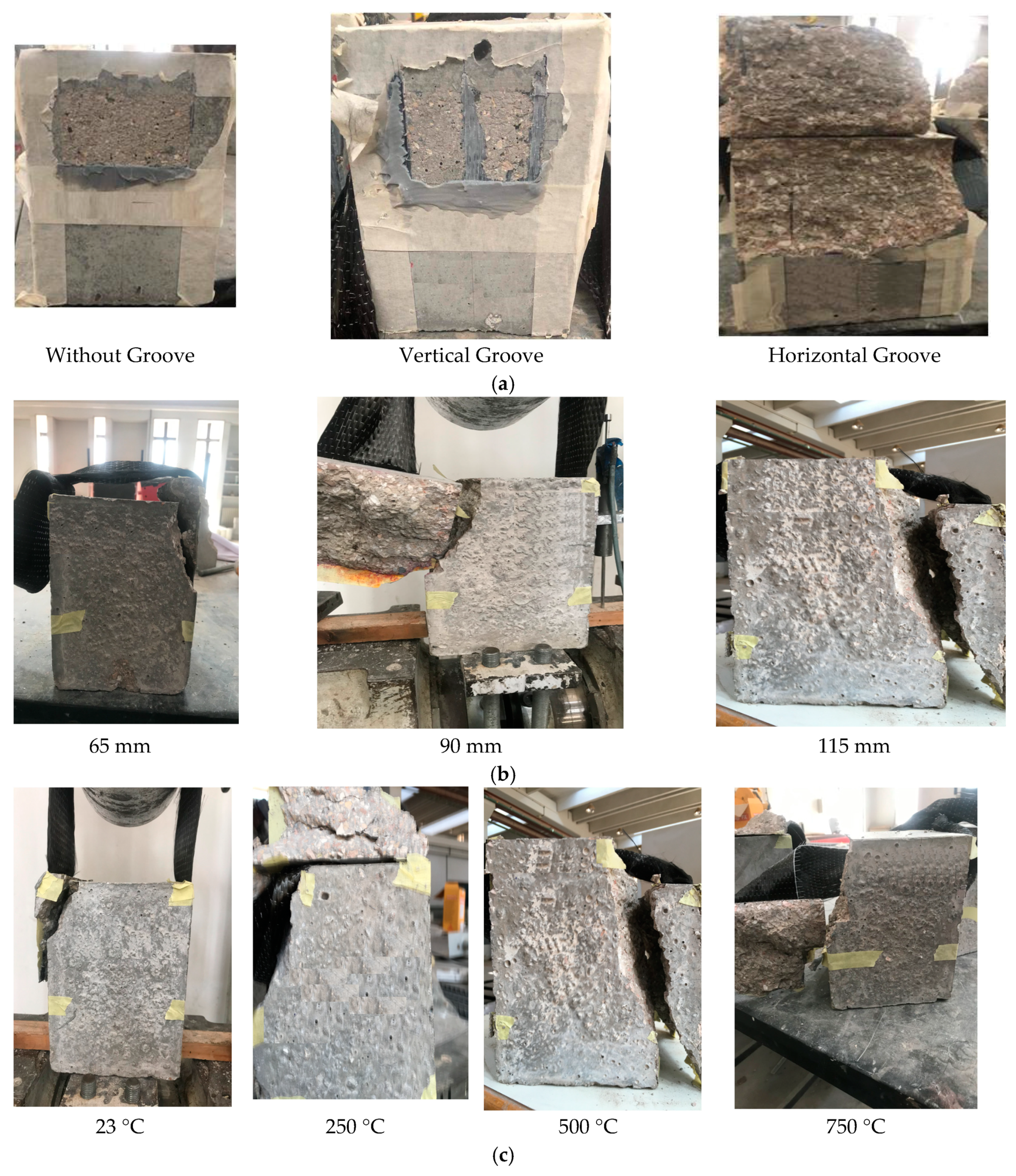
3.2. Mode of Failure
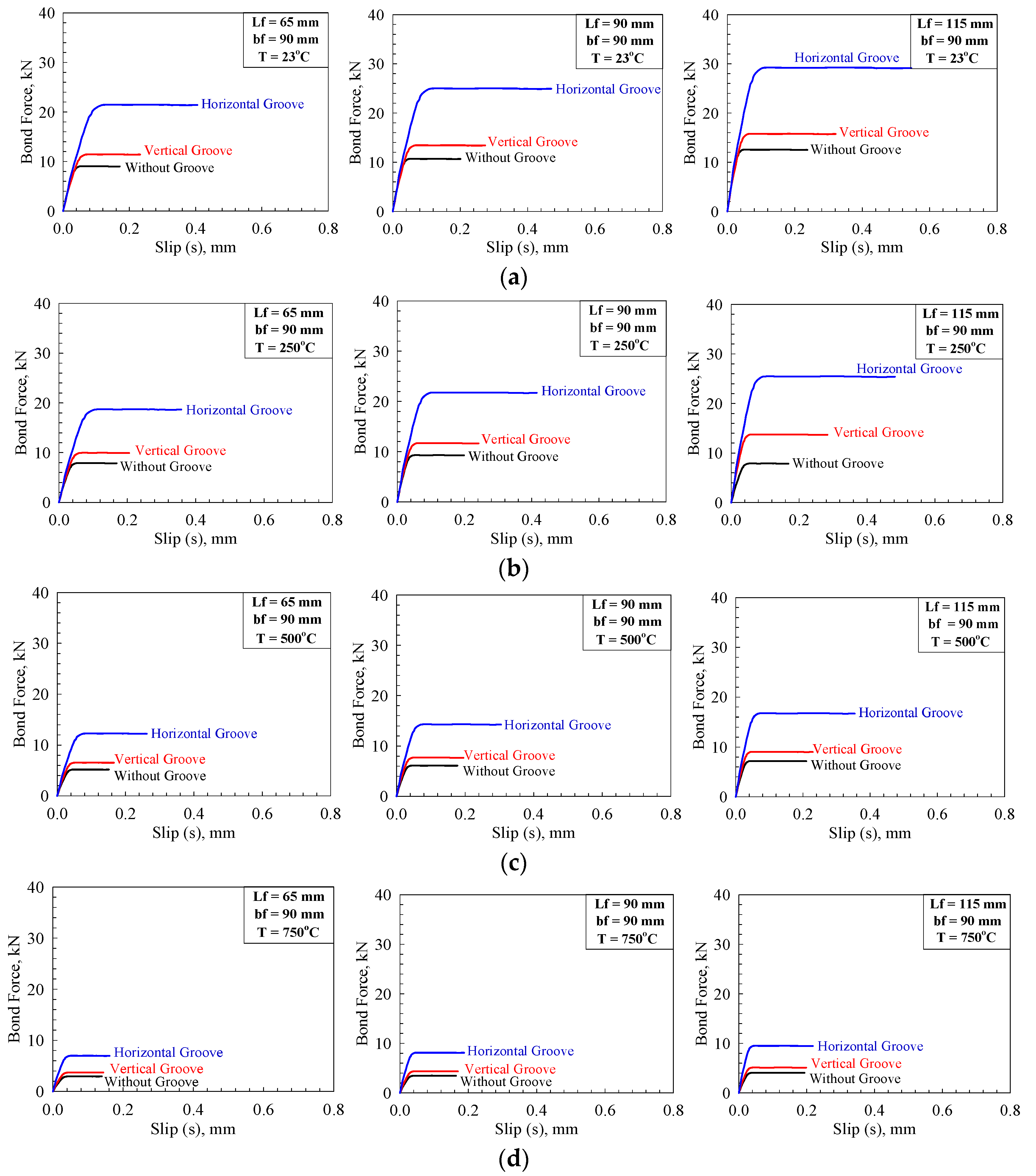
3.3. Bond Force–Slippage Responses
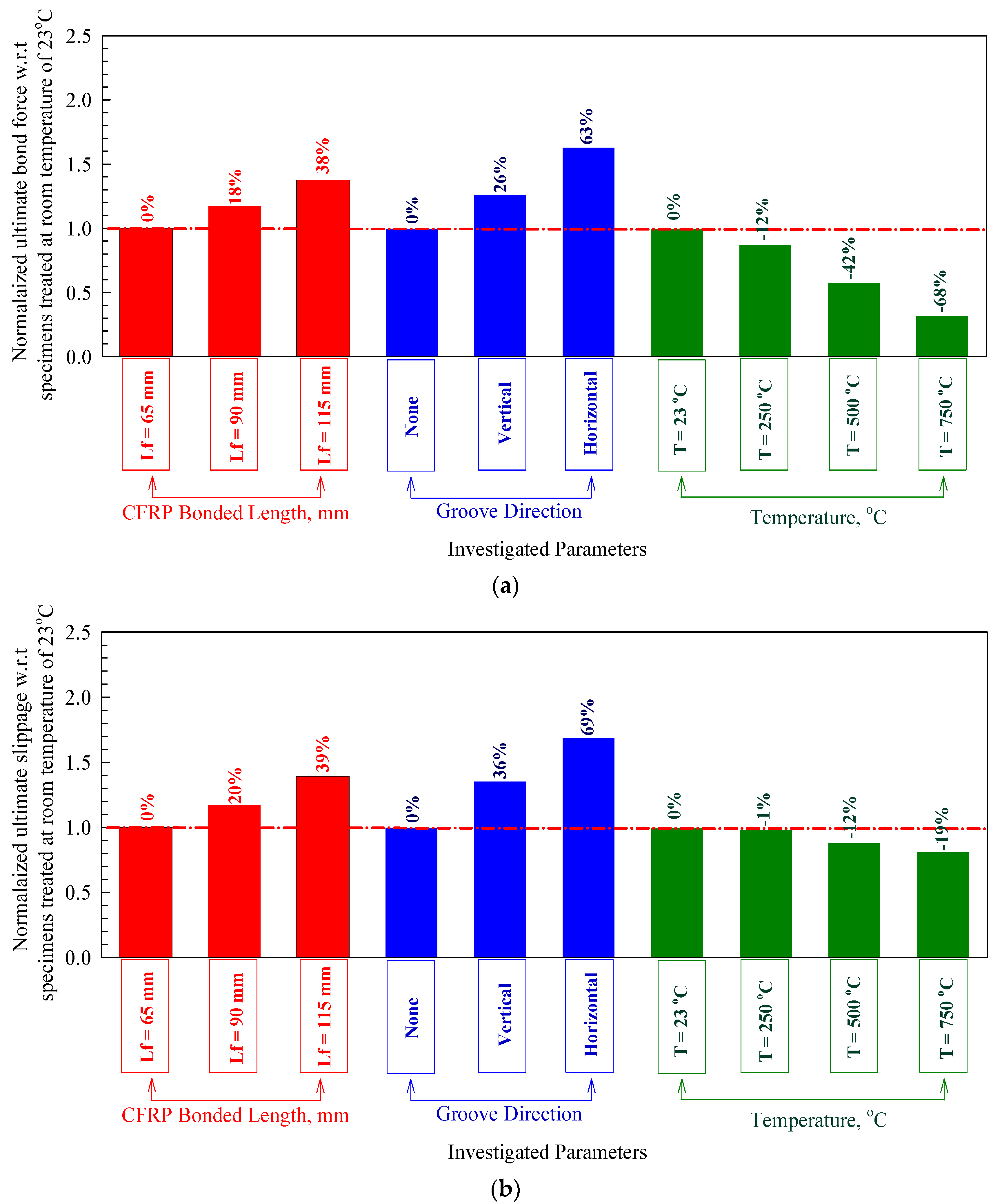
3.4. Ultimate Bond Force and Slippage
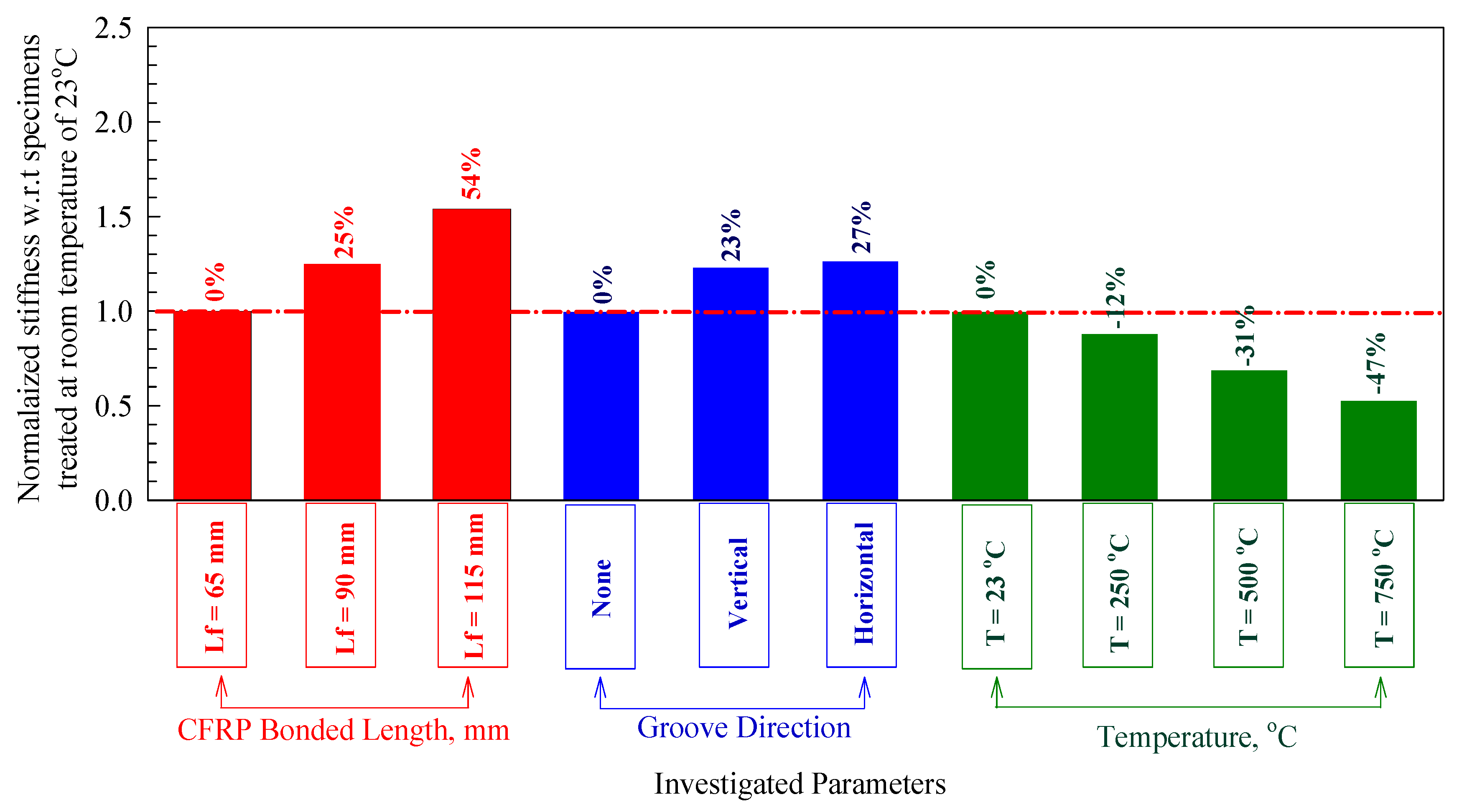
3.5. Stiffness
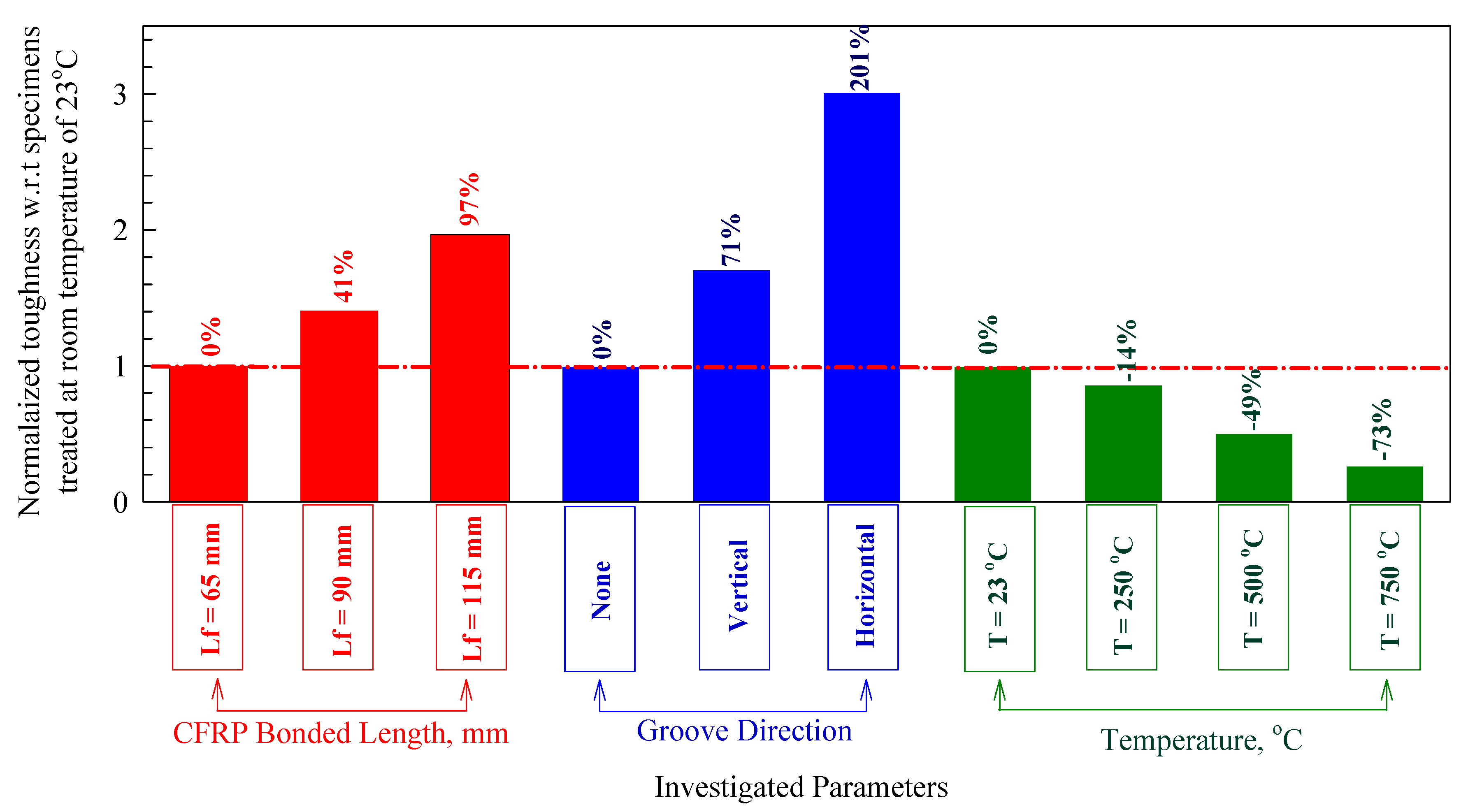
3.6. Toughness
4. Conclusions
- (1)
- The de-bonding failure of the specimens without anchored grooves and with vertical grooves was either through peeling-off of the concrete or shearing in the concrete surface. With the increase in horizontal grooves, the bond was enhanced in strength, as was evident from the amount of concrete left hanging onto the CFRP sheets when the surface failed in adhesion.
- (2)
- The bond force–slippage curve is split into two sections. The first is from the point of no zero loading up to the point of the emergence of CFRP de-bonding. The other section of the curve represents the point of the CFRP delamination from the bonded surface, in which the load is practically persistent, with promptly increasing slippage.
- (3)
- Utilizing the anchoring grooves improves, to a great extent, the behavior of the CFRP–concrete bond. With horizontal grooves, the improvement in the bond strength was around 36%, and this percentage was almost two times the enhancement achieved with vertical grooves.
- (4)
- This study has proven experimentally that horizontal grooves provide a great enhancement in ultimate slippage and bond strength. Therefore, the method of installing CFRP sheets and horizontal grooves lead to an adequate mode of failure.
- (5)
- Using the groove method has proven its practicality and cost-effectiveness. Since the epoxy performance is improved based on the groove direction, it is recommended to use horizontal grooves and CFRP sheets to restore the specimen’s original integrity, before de-bonding of CFRP and after attainment of ultimate bond strength.
- (6)
- It has been shown in this study that increasing the length of the bonded CFRP sheets increases the strength of the bond and enhances the ultimate slippage. The reason for these enhancements could be that, when increasing the length, there is an increase in the induced stresses generated by the exerted load. Moreover, the system becomes more uniform when the concentration of stresses is minimized.
Author Contributions
Funding
Acknowledgments
Conflicts of Interest
References
- Bywalski, C.; Drzazga, M.; Kamiński, M.; Kaźmierowski, M. A New Proposal for the Shear Strength Prediction of Beams Longitudinally Reinforced with Fiber-Reinforced Polymer Bars. Buildings 2020, 10, 86. [Google Scholar] [CrossRef]
- Triantafyllou, G.; Rousakis, T.C.; Karabinis, A. Corroded RC Beams at Service Load before and after Patch Repair and Strengthening with NSM CFRP Strips. Buildings 2019, 9, 67. [Google Scholar] [CrossRef] [Green Version]
- Spinella, N.; Colajanni, P.; Recupero, A.; Tondolo, F. Ultimate Shear of RC Beams with Corroded Stirrups and Strengthened with FRP. Buildings 2019, 9, 34. [Google Scholar] [CrossRef] [Green Version]
- Fathalla, E.; Salem, H. Parametric Study on Seismic Rehabilitation of Masonry Buildings Using FRP Based upon 3D Non-Linear Dynamic Analysis. Buildings 2018, 8, 124. [Google Scholar] [CrossRef] [Green Version]
- Manie, S.; Jami, E.; Azarian, Z. Simplified Design of FRP-Confined Square RC Columns under Bi-Axial Bending. Buildings 2017, 7, 74. [Google Scholar] [CrossRef] [Green Version]
- Al-Rousan, R.Z. Behavior of macro synthetic fiber concrete beams strengthened with different CFRP composite configurations. J. Build. Eng. 2018, 20, 595–608. [Google Scholar] [CrossRef]
- Al-Rousan, R.Z.; Alhassan, M.A.; AlShuqari, E.A. Shear Nonlinear Behavior of plain concrete beams with DSSF strengthened in flexure with anchored CFRP sheets—Effects of DSSF content on the bonding length of CFRP sheets. Case Stud. Constr. Mater. 2018, 9, e195. [Google Scholar]
- Haddad, R.H.; Al-Rousan, R.Z.; Ghanma, L.; Nimri, Z. Modifying CFRP–concrete bond characteristics from pull-out testing. Mag. Concr. Res. 2015, 67, 707–717. [Google Scholar] [CrossRef]
- Al-Rousan, R.Z. Empirical and NLFEA prediction of bond-slip behavior between DSSF concrete and anchored CFRP composites. Constr. Build. Mater. 2018, 169, 530–542. [Google Scholar] [CrossRef]
- Haddad, R.H.; Al-Rousan, R.Z.; Almasry, A. Bond-slip behavior between carbon fiber reinforced polymer sheets and heat-damaged concrete. Compos. Part B Eng. 2013, 45, 1049–1060. [Google Scholar] [CrossRef]
- Al-Rousan, R.Z.; Al-Saraireh, S. Impact of anchored holes technique on behavior of reinforced concrete beams strengthened with different CFRP sheet lengths and widths. Case Stud. Constr. Mater. 2020, 13, e00405. [Google Scholar] [CrossRef]
- Al-Rousan, R.Z.; Al-Tahat, M.F. Consequence of surface preparation techniques on the bond behavior between concrete and CFRP composites. Constr. Build. Mater. 2019, 212, 362–374. [Google Scholar] [CrossRef]
- Haddad, R.H.; Al-Rousan, R.Z. An anchorage system for CFRP strips bonded to thermally shocked concrete. Int. J. Adhes. Adhes. 2016, 71, 10–22. [Google Scholar] [CrossRef]
- ACI (American Concrete Institute). Guide Test Methods for Fiber Reinforced Polymers (FRPs) for Reinforcing or Strengthening Concrete Structures; ACI 4403R-12; American Concrete Institute: Farmington Hills, MI, USA, 2012. [Google Scholar]
- Fib Task Group. Externally Bonded FRP Reinforcement for RC Structures, 9.3; International Federation for Structural Concrete: Lausanne, Switzerland, 2001. [Google Scholar]
- ACI (American Concrete Institute). Guide for the Design and Construction of Externally Bonded FRP Systems for Strengthening Concrete Structures; ACI 4402R-17; American Concrete Institute: Farmington Hills, MI, USA, 2017. [Google Scholar]
- International Concrete Repair Institute. Selecting and Specifying Concrete Surface Preparation for Sealers, Coatings and Polymer Overlays; ICRI 3102R-2013; ICRI: St. Paul, MN, USA, 2013. [Google Scholar]
- De Lorenzis, L.; Miller, B.; Nanni, A. Bond of Fiber-Reinforced Polymer Laminates to Concrete. ACI Mater. J. 2001, 98, 256–264. [Google Scholar] [CrossRef]
- Toutanji, H.; Ortiz, G. The effect of surface preparation on the bond interface between FRP sheets and concrete members. Compos. Struct. 2001, 53, 457–462. [Google Scholar] [CrossRef]
- Chajes, M.J.; Finch, W.W.; Thomson, T.A. Bond and Force Transfer of Composite-Material Plates Bonded to Concrete. ACI Struct. J. 1996, 93, 208–217. [Google Scholar] [CrossRef]
- Biscaia, H.C.; Micaelo, R.; Teixeira, J.; Chastre, C. Numerical analysis of FRP anchorage zones with variable width. Compos. Part B Eng. 2014, 67, 410–426. [Google Scholar] [CrossRef]
- Iovinella, I.; Prota, A.; Mazzotti, C. Influence of surface roughness on the bond of FRP laminates to concrete. Constr. Build. Mater. 2013, 40, 533–542. [Google Scholar] [CrossRef]
- Ueda, T.; Dai, J.G. Interface bond between FRP sheets and concrete substrates: Properties, numerical modeling and roles in member behaviour. Prog. Struct. Eng. Mater. 2005, 7, 27–43. [Google Scholar] [CrossRef] [Green Version]
- Mostofinejad, D.; Kashani, A.T. Experimental study on effect of EBR and EBROG methods on debonding of FRP sheets used for shear strengthening of RC beams. Compos. Part B Eng. 2013, 45, 1704–1713. [Google Scholar] [CrossRef]
- Moshiri, N.; Tajmir-Riahi, A.; Mostofinejad, D.; Czaderski, C.; Motavalli, M. Experimental and analytical study on CFRP strips-to-concrete bonded joints using EBROG method. Compos. Part B Eng. 2019, 158, 437–447. [Google Scholar] [CrossRef]
- Mostofinejad, D.; Mahmoudabadi, E. Grooving as Alternative Method of Surface Preparation to Postpone Debonding of FRP Laminates in Concrete Beams. J. Compos. Constr. 2010, 14, 804–811. [Google Scholar] [CrossRef]
- Hong, S.; Park, S.-K. Effect of prestress and transverse grooves on reinforced concrete beams prestressed with near-surface-mounted carbon fiber-reinforced polymer plates. Compos. Part B Eng. 2016, 91, 640–650. [Google Scholar] [CrossRef]
- Jiang, C.; Wan, B.; Wu, Y.F.; Omboko, J. Epoxy interlocking: A novel approach to enhance FRP-to-concrete bond behavior. Constr. Build. Mater. 2018, 193, 643–653. [Google Scholar] [CrossRef]
- Chen, C.; Li, X.; Wang, X.; Sui, L.; Xing, F.; Li, D.; Zhou, Y. Effect of transverse groove on bond behavior of FRP-concrete interface: Experimental study, image analysis and design. Compos. Part B Eng. 2019, 161, 205–219. [Google Scholar] [CrossRef]
- Hosseini, A.; Mostofinejad, D. Effect of groove characteristics on CFRP-to-concrete bond behavior of EBROG joints: Experimental study using particle image velocimetry (PIV). Constr. Build. Mater. 2013, 49, 364–373. [Google Scholar] [CrossRef]
- Hosseini, A.; Mostofinejad, D. Experimental investigation into bond behavior of CFRP sheets attached to concrete using EBR and EBROG techniques. Compos. Part B Eng. 2013, 51, 130–139. [Google Scholar] [CrossRef]
- Biscaia, H.C.; Silva, M.A.G.; Chastre, C. Factors influencing the performance of externally bonded reinforcement systems of GFRP-to-concrete interfaces. Mater. Struct. 2015, 48, 2961–2981. [Google Scholar] [CrossRef]
- Lu, X.Z.; Teng, J.G.; Ye, L.P.; Jiang, J.J. Bond–slip models for FRP sheets/plates bonded to concrete. Eng. Struct. 2005, 27, 920–937. [Google Scholar] [CrossRef]
- Dai, J.; Ueda, T.; Sato, Y. Development of the nonlinear bond stress-slip model for fiber reinforced plastics sheet-concrete interfaces with a simple method. J. Compos. Constr. 2005, 9, 52–62. [Google Scholar] [CrossRef] [Green Version]
- Nakaba, K.; Toshiyuki, K.; Tomoki, F.; Hiroyuki, Y. Bond Behavior between Fiber-Reinforced Polymer Laminates and Concrete. ACI Struct. J. 2001, 98, 359–367. [Google Scholar] [CrossRef]
- Chen, C.; Sui, L.L.; Xing, F.; Li, D.W.; Zhou, Y.W.; Li, P.D. Predicting bond behavior of HB FRP strengthened concrete structures subjected to different confining effects. Compos. Struct. 2018, 187, 212–225. [Google Scholar] [CrossRef]
- Bazant, Z.; Kaplan, M. Concrete at High Temperatures: Material Properties and Mechanical Models; Longman Group Limited: London, UK, 1996. [Google Scholar]
- Lawson, J.R.; Phan, L.T.; Davis, F. Mechanical Properties of High Performance Concrete after Exposure to Elevated Temperatures; Report Submitted to National Institute and Standards and Technology, IR 6475; National Institute and Standards and Technology: Gaithersburg, MD, USA, 2000.
- Dima, M.A. Thermal Mechanical Behavior of Confined Fibrous Lightweight Aggregate Concrete. Master’s Thesis, Department of Civil and Materials Engineering, Jordan University of Science and Technology, Ar-Ramtha, Jordan, 2007. [Google Scholar]
- ASTM C33/C33M-18: Standard Specification for Concrete Aggregates; ASTM International: West Conshohocken, PA, USA, 2018. Available online: www.astm.org (accessed on 6 December 2020).
- Alhassan, M.A.; Al-Rousan, R.Z.; Abu-Elhija, A.M. Anchoring holes configured to enhance the bond-slip behavior between CFRP composites and concrete. Constr. Build. Mater. 2020, 250, 118905. [Google Scholar] [CrossRef]


| Designation | T, °C | Groove Direction | Lf, mm | Load, kN | Slippage, mm | Stiffness, kN/mm | Toughness, kN/mm |
|---|---|---|---|---|---|---|---|
| T23GNLf65bf90 | 23 | None | 9.0 | 9.0 | 0.171 | 213 | 1.38 |
| T23GNLf90bf90 | 10.6 | 10.6 | 0.201 | 267 | 1.97 | ||
| T23GNLf115bf90 | 12.5 | 12.5 | 0.238 | 326 | 2.78 | ||
| T23GVLf65bf90 | Vertical | 11.4 | 11.4 | 0.233 | 263 | 2.38 | |
| T23GVLf90bf90 | 13.4 | 13.4 | 0.274 | 328 | 3.37 | ||
| T23GVLf115bf90 | 15.7 | 15.7 | 0.321 | 404 | 4.71 | ||
| T23GHLf65bf90 | Horizontal | 21.4 | 21.4 | 0.405 | 284 | 7.78 | |
| T23GHLf90bf90 | 24.9 | 24.9 | 0.470 | 356 | 10.77 | ||
| T23GHLf115bf90 | 29.1 | 29.1 | 0.546 | 441 | 14.86 | ||
| T250GNLf65bf90 | 250 | None | 7.9 | 7.9 | 0.169 | 188 | 1.19 |
| T250GNLf90bf90 | 9.3 | 9.3 | 0.198 | 235 | 1.69 | ||
| T250GNLf115bf90 | 10.9 | 10.9 | 0.235 | 288 | 2.39 | ||
| T250GVLf65bf90 | Vertical | 9.9 | 9.9 | 0.205 | 260 | 1.83 | |
| T250GVLf90bf90 | 11.7 | 11.7 | 0.242 | 324 | 2.59 | ||
| T250GVLf115bf90 | 13.7 | 13.7 | 0.283 | 399 | 3.63 | ||
| T250GHLf65bf90 | Horizontal | 18.6 | 18.6 | 0.357 | 280 | 5.98 | |
| T250GHLf90bf90 | 21.7 | 21.7 | 0.415 | 351 | 8.28 | ||
| T250GHLf115bf90 | 25.4 | 25.4 | 0.482 | 435 | 11.43 | ||
| T500GNLf65bf90 | 500 | None | 5.2 | 5.2 | 0.151 | 147 | 0.70 |
| T500GNLf90bf90 | 6.1 | 6.1 | 0.178 | 184 | 0.99 | ||
| T500GNLf115bf90 | 7.2 | 7.2 | 0.210 | 225 | 1.40 | ||
| T500GVLf65bf90 | Vertical | 6.5 | 6.5 | 0.166 | 211 | 0.97 | |
| T500GVLf90bf90 | 7.7 | 7.7 | 0.195 | 264 | 1.37 | ||
| T500GVLf115bf90 | 9.0 | 9.0 | 0.229 | 325 | 1.92 | ||
| T500GHLf65bf90 | Horizontal | 12.3 | 12.3 | 0.262 | 251 | 2.88 | |
| T500GHLf90bf90 | 14.3 | 14.3 | 0.305 | 314 | 3.99 | ||
| T500GHLf115bf90 | 16.7 | 16.7 | 0.354 | 389 | 5.51 | ||
| T750GNLf65bf90 | 750 | None | 2.9 | 2.9 | 0.139 | 113 | 0.37 |
| T750GNLf90bf90 | 3.5 | 3.5 | 0.164 | 142 | 0.52 | ||
| T750GNLf115bf90 | 4.1 | 4.1 | 0.193 | 174 | 0.73 | ||
| T750GVLf65bf90 | Vertical | 3.7 | 3.7 | 0.144 | 138 | 0.48 | |
| T750GVLf90bf90 | 4.4 | 4.4 | 0.169 | 172 | 0.68 | ||
| T750GVLf115bf90 | 5.1 | 5.1 | 0.199 | 212 | 0.95 | ||
| T750GHLf65bf90 | Horizontal | 7.0 | 7.0 | 0.162 | 231 | 1.01 | |
| T750GHLf90bf90 | 8.1 | 8.1 | 0.188 | 290 | 1.40 | ||
| T750GHLf115bf90 | 9.5 | 9.5 | 0.218 | 359 | 1.93 |
| Material | Mixture (50 MPa) |
|---|---|
| Cement | 422 kg/m3 |
| Coarse Aggregate | 706 kg/m3 |
| Fine Aggregate | 621 kg/m3 |
| Water | 147.6 kg/m3 |
| Superplasticizer | As required |
| Sika CFRP Sheet | Fabric Thickness | 0.167 mm (based on fiber content) |
| Fiber Density | 1.82 g/cm3 | |
| Tensile Modulus | 230,000 N/mm2 | |
| Tensile Strength | 4000 N/mm2 | |
| Break Elongation | 1.7% | |
| Sika Epoxy | Tensile Strength | 30 N/mm2 (7 days at +23 °C) |
| E-Modulus | Flexural: 3800 N/mm2 (7 days at +23 °C) Tensile: 4500 N/mm2 (7 days at +23 °C) | |
| Break Elongation | 0.9% (7 days at +23 °C) |
Publisher’s Note: MDPI stays neutral with regard to jurisdictional claims in published maps and institutional affiliations. |
© 2020 by the authors. Licensee MDPI, Basel, Switzerland. This article is an open access article distributed under the terms and conditions of the Creative Commons Attribution (CC BY) license (http://creativecommons.org/licenses/by/4.0/).
Share and Cite
Al-Rousan, R.; AL-Tahat, M. An Anchoring Groove Technique to Enhance the Bond Behavior between Heat-Damaged Concrete and CFRP Composites. Buildings 2020, 10, 232. https://doi.org/10.3390/buildings10120232
Al-Rousan R, AL-Tahat M. An Anchoring Groove Technique to Enhance the Bond Behavior between Heat-Damaged Concrete and CFRP Composites. Buildings. 2020; 10(12):232. https://doi.org/10.3390/buildings10120232
Chicago/Turabian StyleAl-Rousan, Rajai, and Mohammad AL-Tahat. 2020. "An Anchoring Groove Technique to Enhance the Bond Behavior between Heat-Damaged Concrete and CFRP Composites" Buildings 10, no. 12: 232. https://doi.org/10.3390/buildings10120232