1. Introduction
Sustainable development in the building sector refers to numerous issues of global concern, as energy conservation or reduction of pollution emitted to the atmosphere in the process of manufacturing, exploitation and demolition [
1]. It also embraces, however, the question of indoor environment quality. As the average inhabitant of the European climate zone spends about 80% of their life indoors [
2], it becomes obvious that indoor conditions can significantly affect the quality of life in general. This concerns residential buildings in particular, where acoustic performance plays an important role in the total rating system.
Sustainable development in the construction industry is quite often only associated with so-called “green constructions”. Thus, in order to extend and complete this understanding, this article deals with the acoustic quality aspect, particularly the impact noise transmitted between dwellings. This is one of the most common causes of dissatisfaction among residents of multi-occupancy buildings. Such complaints occur mainly in buildings of a lightweight structure, even if the basic requirements regarding impact sound insulation are satisfied [
3]. The reason can be traced in walking sounds, in particular the sound of bare feet [
4]. The level of dissatisfaction is very much dependent on the actual noise spectrum, which usually differs from the standardized source of impact noise used for assessing the sound insulation, as well as on standard curves used to determine single-number indices that are used for rating [
5].
The increasing use of lightweight structures in housing results mostly from sustainable development rules, which promote reduction in energy consumption in all stages of a building’s life cycle, the application of effective insulations and the reduction of the use of heavy machinery at the construction site [
6,
7]. In effect, there is a surge of interest in wooden or steel lightweight floors. In acoustic terms, they are not as well recognized as traditional heavyweight structures.
In practice, in order to reduce impact sounds, different floor covering systems are used. Basically, floor coverings are tested in the laboratory on a heavyweight reference floor. Current databases containing acoustic parameters of different building products only include these results because most laboratories are not equipped with lightweight reference floors. In addition, the three different floors of various types defined in the standard are confusing and require three different testing facilities. Then, a vital question arises about the efficacy of the application of previous results, obtained on the traditional heavy standard floors, to the lightweight structures, and the need for a re-examination of existing products on lightweight reference floors.
The aim of this study was to investigate the behavior of floor coverings depending on the basic floor on which they are used, point out differences and propose a method of evaluating the acoustic properties of a wooden floor with a covering on the basis of the traditional test carried out on a heavyweight reference floor. The research is based on laboratory measurements.
2. Experiences to-Date and Standard Rating Methods
The very first common impact sound insulation rating method was determined in 1968 [
8] based on the reference curve, which was introduced and standardized for the first time as the German standard in 1953 [
9]. This method has been used until now; the present rating system [
10] does not vary significantly from the initial one. The shape of a reference curve is identical, while only the condition on the maximum allowable unfavorable deviation (8 dB) was removed in a revision of the standard published in 1982 [
11].
The next revision of the standard [
12] introduced an additional weighting procedure and a new indicator called ‘spectrum adaption term, C
I’, that also takes into account the unweighted impact sound level. This term may also be calculated for an extended frequency range, starting at 50 Hz up to 3150 Hz. The standard provided the procedure to evaluate the weighted reduction of impact sound pressure level by floor coverings, as well as the equivalent weighted normalized impact sound pressure level of bare heavy floors. Both indices are intended for the prediction of the impact sound pressure level of the considered heavy floor together with its floor covering.
The most recent revision of the standard [
10] implements an analogous process of calculating the weighted reduction in impact sound pressure level by floor coverings on lightweight floors, although it does not provide any information on its application. Hence, it is practically impossible to use these indices to predict the sound pressure level of a lightweight floor.
In addition to the standard methods, a number of researchers has investigated a more accurate rating system that corresponds more precisely to the residents’ subjective judgments. Problems with the weighted normalized impact sound pressure level were already pointed out in the 1960s by e.g., Gösele [
13] and Fasold [
14]. Later, Gomperts [
15] indicated dB(A) as the most adequate rating unit for all kinds of noise. In the same study, as an impact sound insulation index he considered the impact sound margin as a difference between the fictitious A-weighted impact sound pressure level in a receiving room (a standard situation) and the measured normalized impact sound pressure level in the same room. The source of the impact noise was a standard tapping machine. In his opinion, this method was simple, straightforward and logical while all the definitions were explicit.
Gerretsen [
16] noted that the method of rating the impact sound insulation according to [
8] is not satisfactory. He pointed to the differences in the spectrum shapes of the tapping machine noise and real-life impact noises, such as walking or moving furniture. As a solution to this problem, some changes in reference values were proposed. These changes were based on differences in the spectrum shapes, determined by measurements carried out on different floors. The proposed reference values for impact sound insulation differ from standard ones especially in the range of the 2 kHz frequency, which is 22 dB higher than the ISO reference curve.
Bodlund [
17] investigated a total number of 350 flats in terms of impact sound insulation. Alternative reference curves were presented and analyzed. He concluded that it is possible to obtain better correlation between the mean subjective scores and the respective mean indices for all types of floors by replacing the standard reference curve by a contour with emphasis laid on the low and middle frequency bands. He also proved that the 8dB rule should be excluded for the sake of simplicity, and that the best course of action would be to adhere to the ISO method applicable at the time.
Bodlund [
17] also pointed that the suggested method is somewhat more accurate on timber floors than on concrete floors. Bodlund’s research was reviewed in depth in 2010 by Hagberg [
18], who selected part of the original data and expanded it with his own measurements. Implementing an updated reference contour resulted in the increase of the correlation coefficient from 84 to 87%.
A different approach was proposed by Scholl [
19]. The idea was to use the impact sound insulation index instead of the impact sound pressure level, as impact sound levels are strictly attached to a source (standard tapping machine), which is very seldom found in regular multi-occupancy buildings. He calculated a ratio of the impact power provided by the standard tapping machine to the radiated sound power into the receiving room, which yielded the impact sound reduction index, R
impact. He based his calculations on an energetic sum of normalized sound pressure levels, L
n,sum. Existing index L
n,w + C
I,50–2500 (being the total sound power level from 50 to 2500 Hz in a receiving room) was used in order to arrive at the new impact sound reduction index:
Kylliäinen et al. [
20] carried out a psychoacoustic experiment regarding the impact sound insulation of concrete floors. Eight single number quantities were studied on the basis of correlation analysis between them and subjective ratings of annoyance or loudness. It was shown that when the impact sound source was walking in socks, no correlation between the subjective annoyance or loudness and any of the objective single number quantities was found. The conclusion was that there is need to develop single number quantities of impact sound insulation, which would correlate better with the general sound types.
Two years later, Kylliäinen et al. published a paper [
21] in which they presented five reference spectra, each for a different sound type, which correlated better with the subjective annoyance of the impact sounds than any of the single-number quantities presented in the ISO 717-2 standard. In the same paper, an optimized reference spectrum was also proposed, which could be used to determine the annoyance of all five sound types reasonably well (r
2 = 0.93 compared to r
2 = 0.86 for L’
n,w + C
I,50–2500). All curves were derived from an algorithm for finding the minimum of a constrained non-linear multivariable function. The study was based on measurements of concrete floors and did not involve lightweight constructions.
For over 60 years, one rating system has been used to describe the impact sound insulation of floors. It is unlikely that this will change in the near future, and the tapping machine will probably remain as the primary impact sound [
22].
5. Methods
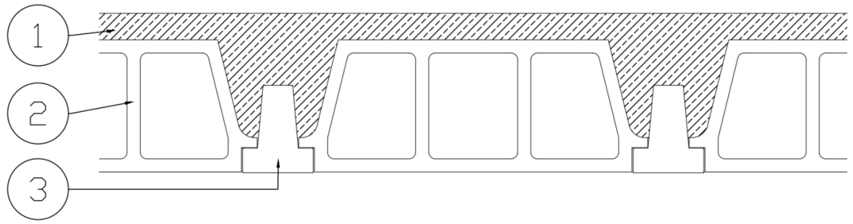
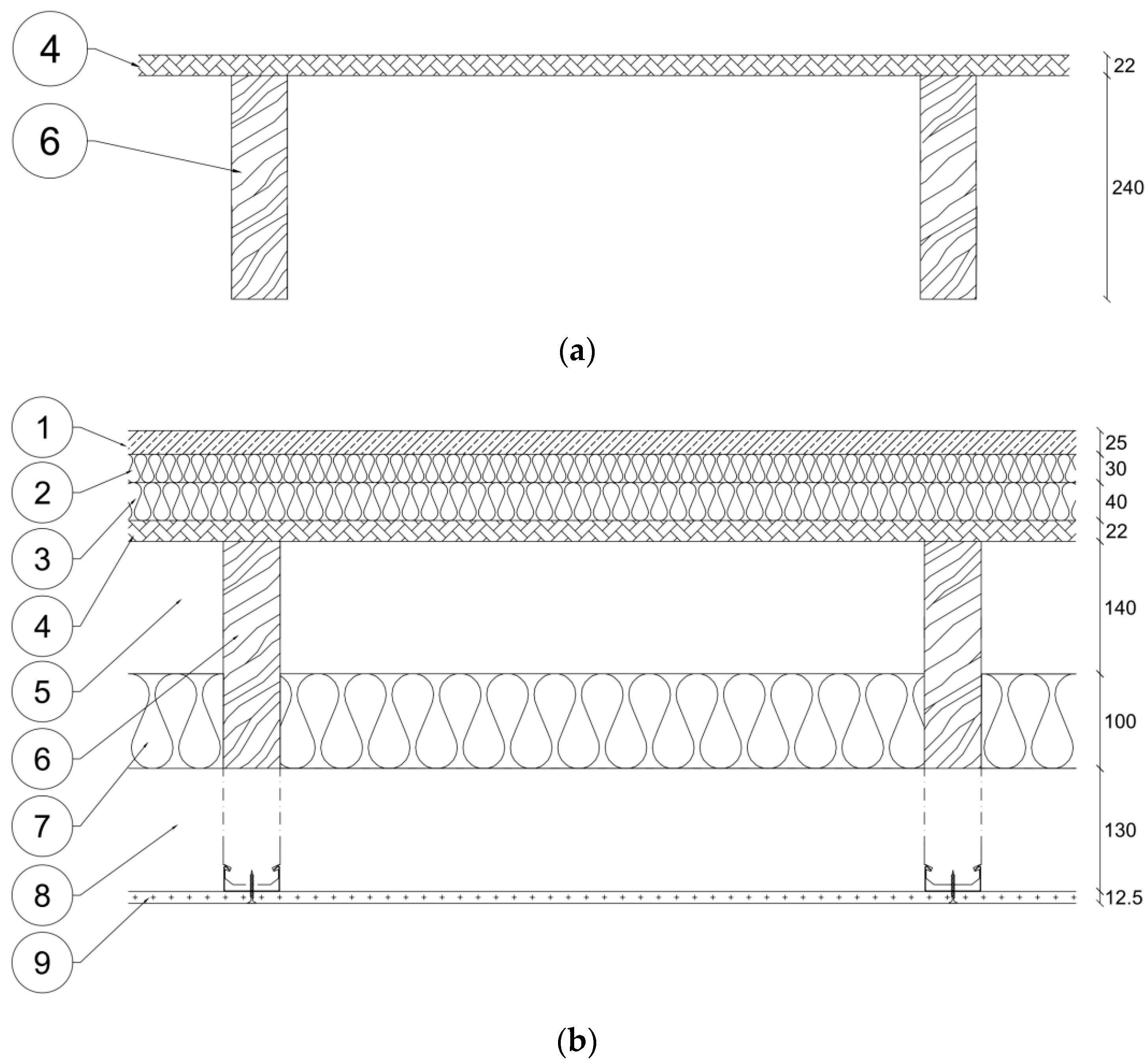
The test facility with the heavyweight reference floor (model 0) consisted of two chambers, with the same 64 m
3 volume and a 140 mm thick concrete floor separating them. The investigated floor models (models 1–4) were mounted on another test facility consisting of two chambers with a volume of 100 m
3 (source room) and 90 m
3 (receiving room) respectively. The test opening dimensions were 4230 mm × 2740 mm. Volumes and dimensions of both test facilities were in accordance with [
24]. In each case, the standard tapping machine was placed on the floor in six different positions according to the standard’s requirements. Average sound pressure level in one-third octave bands was measured in the receiving room with a continuously moving microphone. Average sound pressure level in the receiving room was obtained by integration over time and space. Reverberation time, T, was measured in the receiving room and used for the calculation of the correction factor in the formula for the normalized impact sound pressure level,
where L
i is the average sound pressure level in one-third octave bands in the receiving room, A is the equivalent sound absorption area in the receiving room in m
2, and A
0 is the reference equivalent sound absorption area in m
2 (A
0 = 10 m
2). The instrumentation system used in all tests met the requirements of Class 1 instrument. The results were presented as a reduction of impact sound pressure level for each one-third octave bands, while single-number quantities were calculated in accordance with [
10] and, also, according to the new procedure proposed by the authors.
6. Results and Discussion
The present study aimed at examining the difference in the acoustic properties of a floor covering depending on the floor on which it is applied.
Figure 5 presents the direct reduction in impact sound pressure level caused by the investigated covering. Good agreement of results was observed for three different heavyweight floors (models 0, 1 and 2). Despite different structures and mass per unit areas, all three curves are very similar. On the other hand, the results obtained for lightweight floors vary, particularly in the high frequency area. The reason may be related to the different damping of impact sounds during their excitation due to different hardness of the basic floor surface [
32]; in the case of OSB panels, this is significantly lower than for concrete slabs.
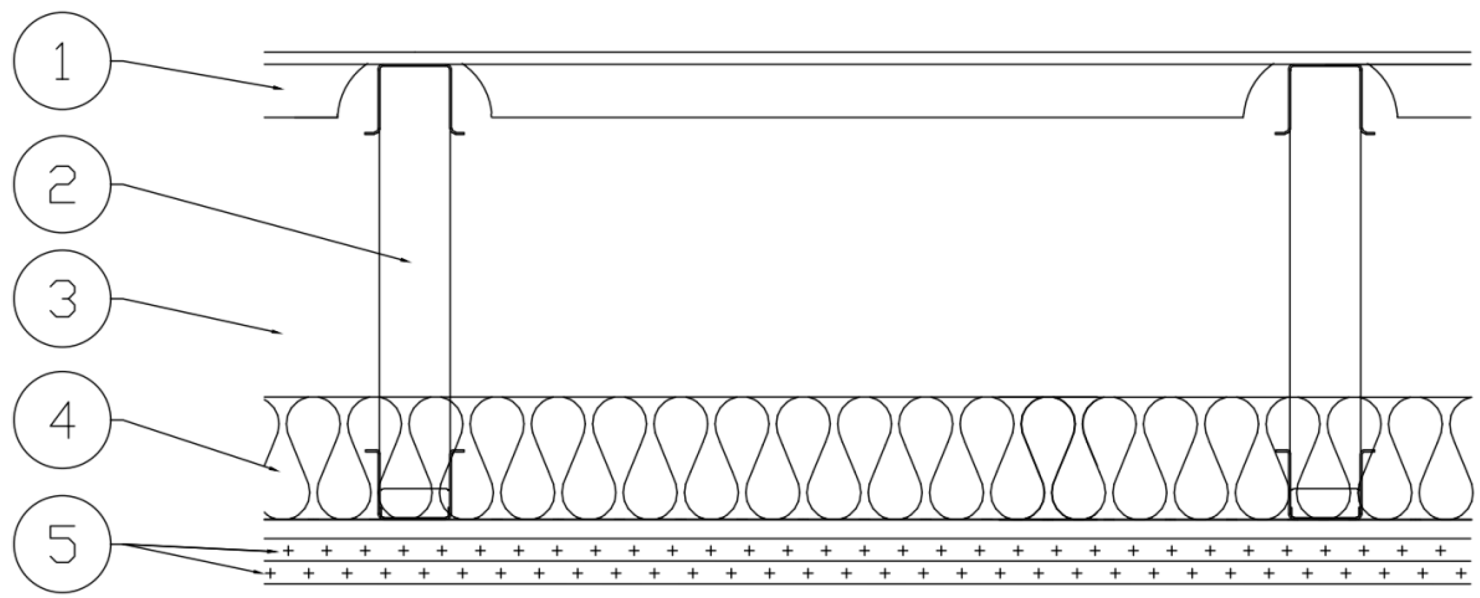
Models 3b and 3c are equipped with floating floors so they are not simple basic structures but combined floor systems. Attention was drawn to the mineral wool used as the resilient layer in the floating floors. In the case of model 3b (thicker layer), dynamic stiffness was 8 MN/m3, slightly lower than for model 3c (10 MN/m3). This means that the internal damping of model 3b was higher, which resulted in worse performance of the floor covering itself. Unfortunately, the results obtained at high frequencies for models 3a and 3b are influenced by background noise so they cannot be properly analyzed. This is due to the floor’s high insulation in this frequency range. The above may confirm that the reduction of impact sound caused by the covering is influenced by the internal damping of a floor, as well as the initial hardness of the basic slab surface. The results obtained for the metal frame floor (model 4), however, are confusing. This has hard metal surface on top, the metal frame, and the suspended ceiling beneath it. Despite the hard surface and the low initial attenuation of impact sounds, the influence of the covering tested, at high frequencies is significantly lower than for a concrete slab.
Single number quantities are presented in
Table 2. Weighted impact sound pressure level, weighted reduction of impact sound pressure level, ΔL
w, and equivalent weighted normalized impact sound pressure level of a bare heavy floor, L
n,eq,0,w, were calculated according to [
10]. Direct reduction of impact sound pressure level, ΔL
w,direct, was calculated by subtracting the weighted impact sound pressure level of the floor with an investigated covering, L
n,w,with, from that without covering, L
n,w,without.
The values of ΔL
w,direct obtained for different floors with the same covering are quite different. In general, the tendencies are consistent with the relationships shown in
Figure 5. In the case of a beam and hollow-pots floor (models 1 and 2), the values of ΔL
w,direct are almost the same as those obtained for a heavyweight concrete floor ΔL
w, (model 0), whereas for structures deviating significantly from the heavy reference floor the covering behaves differently.
For this reason, in the first step a new indicator, ΔL
w,custom, was introduced, which is better adjusted to lightweight frame floors. The quantity is calculated in the same way as ΔL
w, but refers to the real structure, and not the reference floor. The results collected in
Table 2 show that these values are also quite different depending on a real basic floor. Then it shows that the use of ΔL
w,custom in order to calculate L
n,w,with does also not correlate well with the measured values.
In the next step another indicators were proposed and examined. Weighted impact sound reduction indices for lightweight floors, ΔL
t,1,w,direct, ΔL
t,2,w,direct and ΔL
t,3,w,direct (
Table 2) were calculated by relating the measured values of ΔL
direct to the respective reference curves for the lightweight floors given in [
24]. Nomenclature containing the term “direct” refers to tests carried out on a given, non-reference, floors. These values are much lower than ΔL
w and ΔL
w,custom and, in the case of lightweight floors, correspond much better with the ΔL
w,direct index (
Table 2).
In order to make use of these indices in estimating the acoustic performance of other floors with a covering, the relevant equivalent weighted normalized impact sound pressure level is necessary. In the case of lightweight floors, no specific procedure for calculating such an equivalent level is defined, so the indicators and the method of their determination are proposed below.
The method is analogous to that of a heavyweight floor [
10] and it assumes the use of a reference floor covering with the parameters described in [
24]. The value of a single number indicator ΔL
r,w, however, is taken not 19 dB as for the heavyweight floor, but 4 dB and 10 dB for C1/C2 and C3 lightweight reference floors respectively. The new values were calculated from the actual weighted reduction of impact sound pressure level of a reference floor covering, assuming that it was mounted on a respective reference lightweight floor.
The proposed equivalent weighted normalized impact sound pressure levels of lightweight floors are denoted as L
n,t,1,eq,0,w, L
n,t,2,eq,0,w and L
n,t,3,eq,0,w and are calculated from formulas:
The quantities: L
n,t,1,w, L
n,t,2,w and L
n,t,3,w are calculated as weighted normalized impact sound pressure levels of the considered floors with the reference floor covering (corresponding to C1, C2 or C3 lightweight reference floor type). In the case of lightweight constructions, good conformity was obtained between values calculated according to the proposed method and the measured values of L
n,w,with index (
Table 2). This means that the method shows good promise and encourages further research on the topic.
7. Conclusions and Further Research
Present methods of impact sound insulation prediction for lightweight floors are not fully defined and need to be developed. A new indicator—the equivalent weighted normalized impact sound pressure level of lightweight floors (Ln,t,1,eq,0,w, Ln,t,2,eq,0,w and Ln,t,3,eq,0,w)—has been proposed. This corresponds to the indicator existing for heavyweight floors.
The results of the preliminary analysis presented in this article show that the proposed method is promising; however, it needs further elaboration and improvements. The initial assumption that the reduction in impact sound pressure level of the reference floor covering is similar regardless of the type of reference floor should be modified. In fact, the acoustic properties of the covering depend on the floor type. For this reason, it is necessary to define the acoustic properties of a reference floor covering intended for prediction of the impact sound insulation of a lightweight floor.
As a next step, a series of tests will be carried out on wooden reference floors for various floor coverings. The same samples will also be tested on a heavyweight reference floor to investigate possible correlations and determine the methods of predicting the acoustic parameters of lightweight wooden floor structures on the basis of data obtained on a heavyweight reference slab. A series of comparative tests will be carried out on real heavyweight and wooden floors to validate the method.
Lightweight structures adhere to sustainable development concepts and are becoming increasingly popular. Proper assessment and prediction methods of their acoustical performance are critical when examining interior living quality, particularly in residential buildings. The method outlined in this article aims to improve the process of forecasting and assessing the acoustic parameters of lightweight floors without the need to re-examine existing floor covering systems on reference lightweight floors.


