Article

Effects of Hardening Model and Variation of Elastic Modulus on Springback Prediction in Roll Forming

1
‏Mechanical Engineering faculty, Tarbiat Modares University, Tehran 14115-111, Iran
2
Engineering faculty, Tafresh University, Tafresh 39518-79611, Iran
*
Authors to whom correspondence should be addressed.
Metals 2019, 9(9), 1005; https://doi.org/10.3390/met9091005
Submission received: 19 July 2019 / Revised: 27 August 2019 / Accepted: 5 September 2019 / Published: 12 September 2019

Abstract

:
In this paper, the uniaxial loading–unloading–reloading (LUR) tensile test was conducted to determine the elastic modulus depending on the plastic pre-strain. To obtain the material parameters and parameter of Yoshida-Uemori’s kinematic hardening models, tension–compression experiments were carried out. The experimental results of the cyclic loading tests together with the numerically predicted response of the plastic behavior were utilized to determine the parameters using the Ls-opt optimization tool. The springback phenomenon is a critical issue in industrial sheet metal forming processes, which could affect the quality of the product. Therefore, it is necessary to represent a method to predict the springback. To achieve this aim, the calibrated plasticity models based on appropriate tests (cyclic loading) were implemented in commercial finite element (FE) code Ls-dyna to predict the springback in the roll forming process. Moreover, appropriate experimental tests were performed to validate the numerical results, which were obtained by the proposed model. The results showed that the hardening models and the variation of elastic modulus have significant impact on springback accuracy. The Yoshida-Uemori’s hardening represents more accurate prediction of the springback during the roll forming process when compared to isotropic hardening. Using the chord modulus to determine the reduction in elastic modulus gave more accurate results to predict springback when compared with the unloading and loading modulus to both hardening models.

1. Introduction

A phenomenological plasticity model is made up of several ingredients such as a hardening law. The variation of elastic modulus has an important effect on springback prediction accuracy.
Sheet metal forming processes like roll forming, bending, stretching, deep drawing [1] and stamping are widely used in the production processes, especially in the automobile industries [2]. The management of sheet properties can also be successfully implemented by creating a special internal architecture, for example, by differential heat treatment [3].
Getting a product without causing defects that may happen during or after the process such as wrinkling, surface distortion, and springback is considered to be an essential problem in sheet metal forming processes. Springback phenomenon is one of the most complex and difficult issues in the industry [4].
Springback is an unwanted deformation that results from the interaction between elastic and plastic regions in the sheets after the forming process. As the sheet metal’s strength and formability increase, serious defects including springback and side-wall curl will also take place.
These distortions can have a destructive effect on the final shape of the products, which make it difficult to fulfill their desired dimensional precision.
Subsequently, due to the absence of dimensional accuracy, the resulting product struggles to assemble with the part in a sub-assembly way or can diminish the function of the downstream operations.
The springback phenomenon in sheet metal forming processes has been investigated by several researchers. Additionally, the springback effect has been excessively described using the finite element (FE) simulation.
Distinct methods have been used to estimate the constant elastic modulus in the course of deformation in order to predict the springback. However, researchers have recently showed that the elastic modulus variation should also be taken into consideration for precise prediction of springback.
Several researchers have reported that the estimated springback is extremely affected by the variation of the elastic modulus, which in turn relies on plastic strain, and nearly all metals are of inflexible retrieval behavior after plastic distortion [5].
As mentioned by Yang et al. [6], both macroscopic and microscopic quantifications have been used to examine the effectiveness of plastic distortion on the elastic modulus. It has been deduced that the movement of the mobile and pile-up dislocations is the primary reason for the reduction of elastic modulus.
Yoshida et al. [7] concluded that elastic modulus was not stable in the unloading phases, and suggested an exponential formula to evaluate the elastic modulus with reference to plastic strain. Therefore, referring to Yoshida-Uemori’s formula, further precise results have been detected in the residual curvatures of side-wall in the U-bending test.
Previous studies did not examine the effect of the variation of elastic modulus on productive processes, but focused on the reasons for this change and confirmed it.
Yang et al. [8] proposed an analytical model to estimate springback in the air-bending of advanced high strength steel (AHSS). The precision of springback prediction increases when the mechanical behavior is fully defined. Therefore, the quantity of springback is firmly related to two essential factors, namely, the stresses formed in the material before the unloading and unloading modulus and compared to the analytical method, the finite element (FE) simulations with the highest amount of unloading modulus exhibited more consistency with the preformed experiments in comparison to the estimations with the lowest amount of unloading modulus. Nevertheless, this analytical model used only the unloading modulus; this limits the conclusiveness of the work.
Yu Hy et al. [9] proposed an empirical formula to describe the relation of elastic modulus with plastic strain. They observed that the springback simulation with varied elastic modulus showed higher accuracy for a U-channel bending process in comparison to the stable elastic modulus. They concluded that inelastic recovery should be taken into consideration in order to enhance the accuracy of springback simulation. They focused on the effect of the variation of elastic modulus and did not study the effect of hardening models.
The variation of elastic modulus with the increase of plastic strain was first investigated by Lems [10]. They reported that point defects and dislocations were the major reasons for this alteration. In addition, it was demonstrated that the elastic modulus saturation with two models was promptly dependent on the representation of the dislocation by an elastic string, which in turn depends on the kink movement.
A new hypoelastic model was proposed to describe this complex nonlinear behavior by Ghaei [11]. The model can be easily utilized in any plasticity constitutive law. The constitutive law was implemented into the ABAQUS commercial package via a user material subroutine UMAT. A comparison between the experimental response and its simulated response showed that the model was able to describe the material response fairly well. Furthermore, for an accurate springback prediction in sheet metal forming, it is very important to thoroughly understand the hardening models that describe proper material behavior.
Kim and Kimchi [12] studied the pre-strain effect on springback of a dual phase steel for an S-rail stamping test. The springback magnitude has been shown to be considerably affected by the distortion histories of steel parts. Furthermore, Yoshida-Uemori’s hardening model exhibited better correlations with springback measurements in S-rail stamping when compared to the isotropic hardening models regardless of the elastic modulus models.
Abvabi et al. [13] investigated the reduction of the elastic modulus of high strength steel alloys (HSS) after plastic distortion. The results showed that the reduction of elastic modulus with pre-strain significantly influences springback in the roll forming of HSS alloys compared to when a softer steel is formed.
Eggertsen and Mattiasson [14] reported that the estimated springback is highly influenced by the variation of elastic modulus as a result of plastic straining. They also found that the hardening law option slightly affects the springback estimation in comparison to the impact of the elastic modulus variation. They used the variation of elastic modulus with the pre-strain elastic modulus, namely “unloading modulus”, but they did not examine chord and loading modulu.
The FE code JSTAMP/Ls-dyna was used for implementing the established process simulation and springback prediction that takes place in an automobile body panel by Hu et al. [15]. In this situation, the Yoshida-Uemori’s model was chosen to identify the anisotropic material behavior of sheet metal in the course of deformation. As a consequence, it was deduced that the Y-U material model could be proposed for predicting the springback of high strength steels.
Ulhassan et al. [16] studied the impact of the Young’s modulus variation in deep drawing and springback simulations and examined blank holder’s variance in the course of deep drawing for the springback reduction of the steel (DC04, DP600, and DP1000). It was shown that all materials displayed a considerable decrease in the elastic modulus prior to the achievement of the saturation value. Therefore, the fluctuation in the amount of elastic modulus should be taken into consideration in order to enhance the accuracy of springback estimation in deep drawing.
Springback behavior of sheet materials has been studied for many years. This issue became more important in materials with high yield stress. With ever continuing advancements in the material technology and development of new materials, the need for accurate springback prediction has also become more profound. As mentioned in the above, many researchers have studied the effect of the variation of elastic modulus on springback in sheet metal forming processes like bending and stamping, but they did not provide any suggestion for the change of elastic modulus that should be considered (chord–loading–unloading elastic modulus).
Therefore, this work is the first study to investigate the effect of hardening models with a change in elastic modulus (IH and Y-U hardening models with chord–loading–unloading elastic modulus for both of them) on springback in roll forming. Our findings confirmed that using Y-U with the chord elastic modulus gives a more accurate prediction of springback during the roll forming process compared to other results. Hence, the use of chord elastic modulus in simulations to improve springback prediction accuracy is recommended, regardless of the hardening models.
This work is a new study to investigate the effect of both the variation of elastic modulus with pre-strain using the loading, unloading, and chord modulus approaches to determine the change in elastic modulus and the hardening law on springback in roll forming to develop the finite element (FE) simulation and control the springback to an acceptable level. In this study, st-37 steel sheets with the thickness of 2 mm were used. The uniaxial tensile test and tension–compression experiments were employed to determine the material parameters. Finally, the numerically predicted value of the springback was validated by the roll forming experiments.

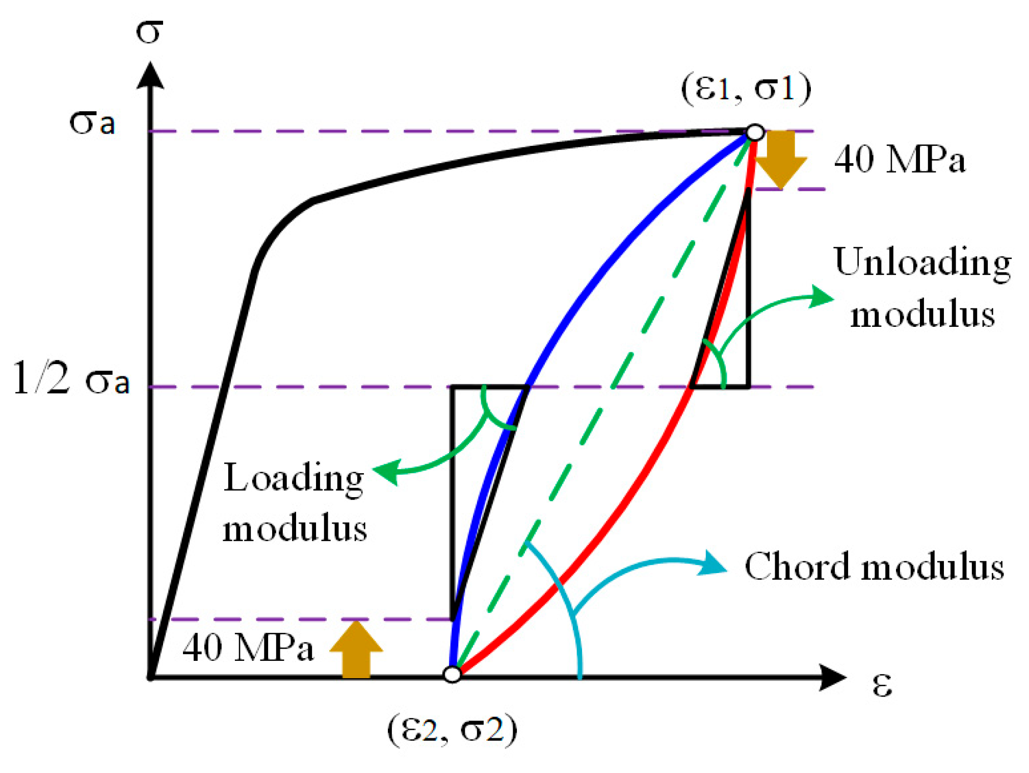
2. Defining the Elastic Modulus Change

The uniaxial loading–unloading–reloading (LUR) tensile test was performed at room temperature to determine the elastic modulus that depends on the plastic pre-strain. An Intsron tensile test machine was utilized in all experiments (INSTRON, Shanghai, China). This machine has a load capacity of 100 kN. Tensile test samples were prepared according to the ASTM E8 standard. The functional equipment of the tension tests is shown in Figure 1. The experiment was repeated with two specimens.
First, a precursory monotonic uniaxial tensile experiment was performed to confirm the degree of elongation uniformity. Then, the sample was loaded up to the required strain, which was accompanied by unloading to zero stress. The specimen was loaded to a specific strain and released again when the loading–unloading cycle was accomplished. The pre-strain levels were set at the following percentages: 0.5%, 0.8%, 1%, 2%, 3%, 4%, 5%, 6%, 7%, 8%, 9%, and 10%. The true stress–strain curves resulting from the experimental cyclic (LUR) tensile tests are represented in Figure 2.
Overall, there was a negative correlation between the elastic modulus of the steel sheets and the effective strain such that as the effective strain rises, the elastic modulus of the steel sheets diminishes. The elastic modulus was calculated for various pre-strain levels using three methods: the loading, unloading, and chord modulus. These methods were used to calculate the elastic modulus of distinct pre-strain levels. In order to prevent the influence of nonlinear effects, the elastic modulus was calculated from 40 MPa. To examine the loading and unloading modulus, part of the flow stress was specified as the boundaries. However, the chord modulus was counted from (ε1, σ1) to (ε2, σ2) and considered as the slope of the entire unloading–loading slope (Figure 3).
A mathematical model is required to implement the elastic modulus variation with respect to plastic strain in FEA simulations. The suggested mathematical variation in the Young’s modulus is represented by the following equation:
E a v = E 0 ( E 0 E a ) [ 1 e ( ξ ε 0 p ) ]
where E 0 represents the initial Young’s modulus; E a v is the average elastic modulus during the forming process; E a describes the Young’s modulus value at an endlessly large plastic strains; and ξ is defined as a material parameter that controls the rate of the Young’s modulus reduction. The Young’s modulus degradation for FE simulations is defined by the previously mentioned mathematical model and the three introduced parameters fended by the curve fitting approach as represented in Figure 4. According to the fitted curve, the loading, unloading, and chord modulus changes of the Yoshida parameters are specified in Table 1 and incorporated into the finite element analysis (FEA).

3. Uniaxial Tensile

Tensile test samples were prepared based on the ASTM E-8 stander to consider the anisotropic plastic behavior of the material. Uniaxial tensile tests were carried out on various samples along different directions (0°, 45°, and 90° degree with respect to rolling directions). An electrical discharge machine (EDM) was used to construct an ASTM E-8 with defined dimension specimens. The anisotropy coefficient or Lankford parameter (r) is defined by the strains in the width and thickness directions. The Lankford parameter r is defined as follows:
r = ε w ε t = ln w w 0 ln t t 0
where ε w and ε t are the strains in the width and thickness directions, respectively; w 0 and w are the initial and final widths and t 0 and t are the initial and final thickness of the specimen, respectively. The mechanical properties together with the Lankford parameter are shown in Table 2.

4. Yoshida-Uemori Model and Cyclic Tension–Compression Test

The Yoshida-Uemori model [6] is one of the most sophisticated models that can reproduce transient Bauschinger effects, permanent softening, and work hardening stagnation during large elasto-plastic deformation. This model uses two surfaces to describe the hardening rule: the yield surface f and the bounding surface F. In the forming process, the yield surface does not change in size, but its center translates with deformation; the bounding surface changes in both size and location.
The surfaces of the Yoshida-Uemori model are shown in Figure 5. The yield surface is defined as follows:
f = σ ¯ ( σ α ) Y = 0
where Y is the size of initial yield surface; σ ¯ is the equivalent plastic stress; and σ and α are the Cauchy stress deviator and the backstress deviator, respectively. The bounding surface is defined by the following equation:
F = σ ¯ ( σ β ) ( B + R ) = 0
The center of the bounding surface is indicated by β ; B is the size of the initial bounding surface; and R is the parameter indicating the isotropic hardening rate. The relative kinematic motion of the yield surface on the bounding surface α * is defined in the following equations:
α = α * + β
α * = C [ a Y ( σ α ) a α * α ] ε ˙ p = 0 a = R + B Y
where C is a material parameter that determines the kinematic hardening rate and ε ˙ p is the effective plastic strain rate. Isotropic hardening at the bounding surface is defined in the following equation:
R ˙ = m + ( Rsat R )   ε ˙ p
Kinematic hardening at the bounding surface is defined in the following equation:
β ˙ = m ( 2 3 b ( σ α ) β )   ε ˙ p
where m is a material parameter that determines the isotropic hardening rate; Rsat is the saturated isotropic hardening stress; and the material parameter b determines the movement of the bounding surface.
Various experimental and theoretical processes were used to acquire the materials’ cyclic loading behavior. In the present work, tension–compression experiments were carried out on a specimen with a 50 mm gauge length to obtain the st-37 hardening behavior and the Yoshida-Uemori’s parameter of the kinematic hardening models.
Particular loading equipment was utilized to avoid deformation of the sheet specimen during its subjection to a tension–compression cyclic load. A specific device was used to clamp the specimen. This device consists of two parallel plates that are attached through coil-springs as represented in Figure 6.
In this study, the optimization code Ls-opt was utilized to characterize the Yoshida-Uemori (Y-U) preliminary hardening parameters including six parameters named as B, m, Rsat, C, b, and h. The Yoshida-Uemori model constants determined for st-37 are presented in Table 3.
In order to determine the material parameters, the simulation curves were created through the implementation of unchanged loading schemes upon 1-element derived from the FE-model. Then, the curve mapping was performed. Next, a primary tensile was loaded up to 0.02 strain, followed by reloading up to 0.06 strain. To further define the material parameters, the experimental curve was specified as a target curve, and the previously mentioned loading conditions were carried out to the 1-element model during the curve mapping procedure. The efficiency of the parameters was improved until it reached a minimum deviation value among the simulation based and the experimental curve. A comprehensive schematic representation for the identification process of the model parameter is represented in Figure 7. Furthermore, a sequential response surface method (SRSM) [17] was used by Ls-opt to minimize the difference between the experimental and calculated stresses [18]. The comparison between the Y-U model estimations with respect to the results of the experimental cyclic test is shown in Figure 8.

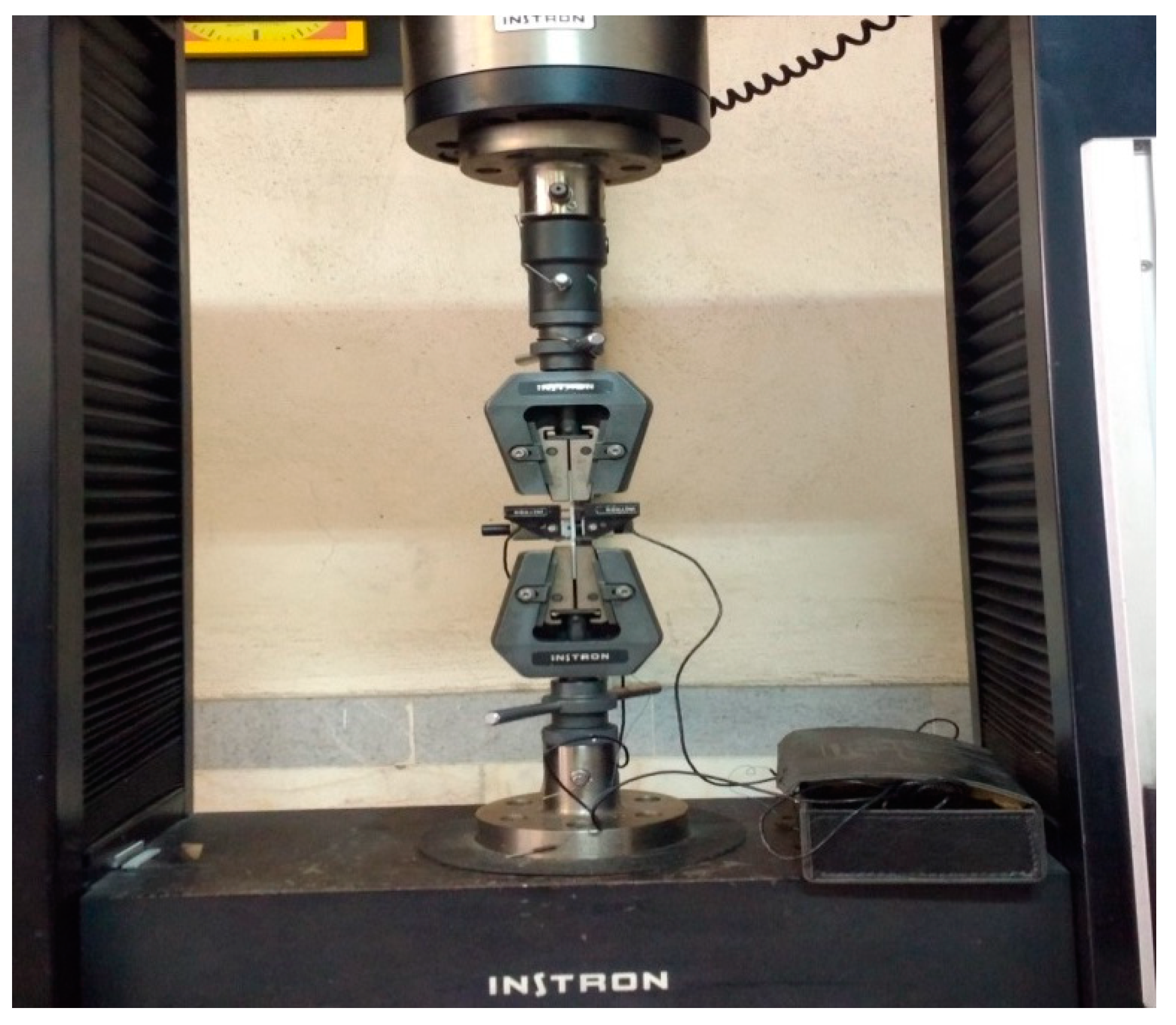
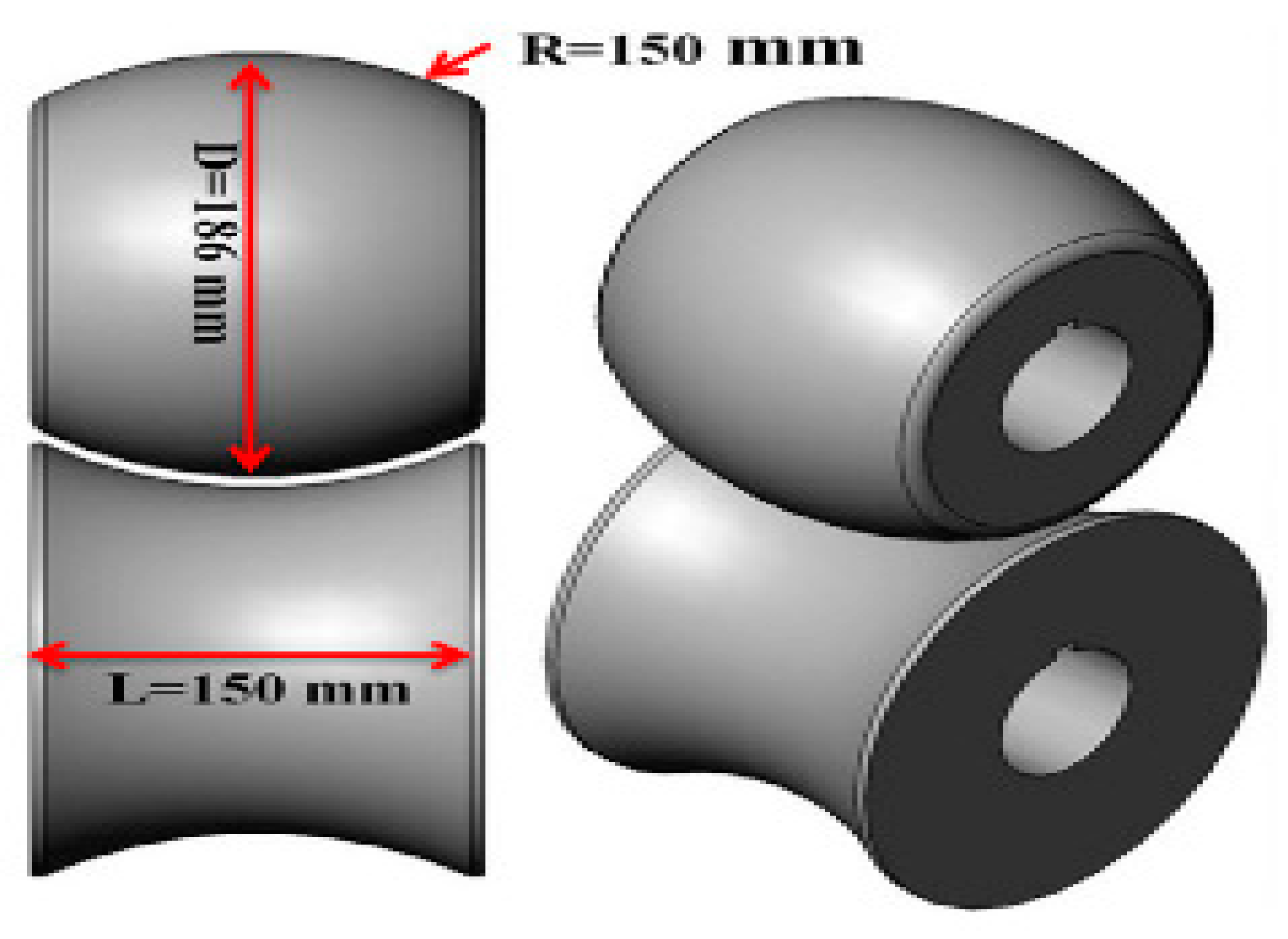
5. Experimental Tests

Roll forming involves uncoiling a long strip of metal and sending it through consecutive sets of roll stand to achieve a required cross-section with no reduction in the strip thickness, except in the localized bend regions. Roll formation of the arc-section was performed in a single step. Both rollers were utilized at the experimental setup stand as shown in Figure 9. The main forming parameters are presented in Table 4.
The setup was composed of an essential gear box with a 1/40 train value and a single subordinate gear box for a stand with a 1/1 train value. The four rollers (A–D) were adaptable in the strips’ transverse orientation so that the strip would be perfectly aligned to the roll forming line as represented in Figure 10.
The eventual geometry of the parts after springback was considered as an essential measurement for evaluating the effect of various hardening models on the accuracy of the FE model results. In order to obtain the three-dimensional geometry of the roll formed samples, an optical measurement method was used. The optical scanner used in these measurements is a range Vision 3D scanner Standard Plus that has a precision of 0.03 mm in the 133 mm × 100 mm × 133 mm range.

6. Finite Element Analysis Model

Simulations of the roll forming process were performed using the commercial finite element Ls-dyna software, taking advantage of an explicit solver for the formation process and an implicit solver for the simulation of the springback. The rollers were specified as a solid mass, and an entirely incorporated element formulation (type 16) was chosen for the forming and springback models. The algorithmic type of contact interfaces, known as “forming one-way surface to surface”, was defined between the roller and sheet metal where the friction coefficient was considered equal to 0.15. A schematic representation of the produced models is presented in Figure 11.

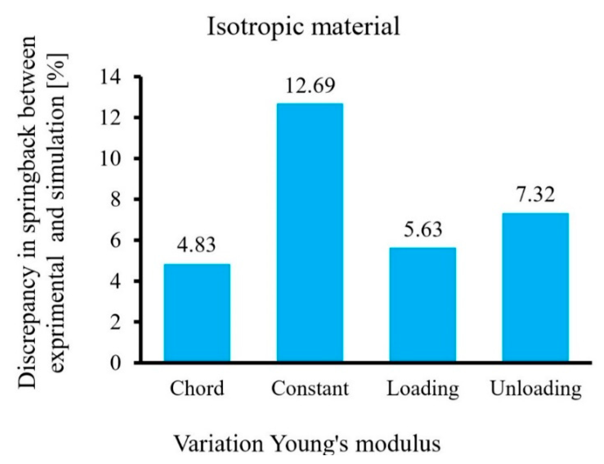
7. Results and Discussion

The difference between the bending arc and the arc sheet metal after release from the roll former was utilized as a measurement of springback. The sheet metal was structured using two distinct models adapted from the Ls-dyna material library:
(1)
MAT 37 (Transversely Anisotropic Elastic Plastic) with four types of isotropic hardening [IH]: (a) constant E model, (b) the loading elastic modulus, (c) the unloading elastic modulus, and (d) the chord modulus.
(2)
MAT 125 (Kinematic Hardening Transversely Anisotropic (Yoshida-Uemori’s model) with three types [Y-U]: (e) the loading elastic modulus, (f) the unloading elastic modulus, and (g) the chord elastic modulus.
In order to evaluate the effects of hardening models and the variation of elastic modulus on springback prediction, the numerically predicted cross-section of the roll formed sample was compared to the experiment results.
The difference between the numerical and experimental results showed that the springback arcs simulated with diverse elastic modulus were closer than those simulated with the constant elastic modulus, as shown in Figure 12. Furthermore, it was found that the simulation using the chord elastic modulus enhanced the accuracy of the springback estimations when compared to the loading and the unloading elastic modulus for both the MAT-37 and MAT-125 material models, as shown in Figure 12 and Figure 13. Moreover, the hardening model had the primary effect on the springback prediction. Therefore, it was concluded that the simulation using MAT-125 (Transversely Anisotropic Elastic Plastic) improved the accuracy of the springback predictions when compared to the utilization of MAT-37 (isotropic hardening), as shown in Figure 14.

8. Conclusions

In summary, this paper presents an effective method for improving the numerical prediction of springback in the roll forming process. Two different hardening models were investigated: isotropic and the Yoshida-Uemori models. The elastic modulus was calculated for various pre-strain levels using three methods: loading, unloading, and chord modulus. The elastic modulus change was investigated for two previous cases (IH and Y-U) to determine the springback test results. Tension–compression, uniaxial tension, and loading–unloading tests were conducted to investigate the hardening behavior, anisotropy coefficient, and change of elastic modulus. The material constants of various constitutive equations were detrained based on the experimental results, and were implemented in the commercial finite element Ls-dyna software for modeling and analyzing springback. FE simulation and experimental were conducted to evaluate springback behavior in roll forming. The change of elastic modulus with pre-strain in the numerical analysis of the roll forming process increased the level of springback predicted; however, the use of the chord modulus gave more accurate results to predict springback when compared with the unloading and loading modulus to both hardening models. In addition, it was confirmed that the accuracy of the finite element analysis could be improved by using the Y-U (Transversely Anisotropic Elastic Plastic) model with the consideration of the elastic modulus degradation, especially using the chord modulus, when compared to the isotropic hardening model.

Author Contributions

Conceptualization, J.N., H.M.N. and S.M.; methodology, J.N., H.M.N. and S.M.; software, J.N.; formal analysis, J.N. and H.M.N.; Data curation, J.N. and S.M.; writing—original draft preparation, J.N.; writing—review and editing, H.M.N. and S.M.

Funding

This research received no external funding

Conflicts of Interest

The authors declare that they have no conflicts of interest.

References

  1. Sheykholeslami, M.; Cinquemani, S.; Mazdak, S. Numerical study of the ultrasonic vibration in deep drawing process of circular sections with rubber die. In Proceedings of the Active and Passive Smart Structures and Integrated Systems XII, Denver, CO, USA, 4–8 March 2018; Volume 10595. [Google Scholar]
  2. Mulidrán, P.; Šiser, M.; Slota, J.; Spišák, E.; Sleziak, T. Numerical prediction of forming car body parts with emphasis on springback. Metals 2018, 8, 435. [Google Scholar] [CrossRef]
  3. Beygelzimer, Y.; Estrin, Y.; Kulagin, R. Synthesis of hybrid materials by severe plastic deformation: A new paradigm of SPD processing. Adv. Eng. Mater. 2015, 17, 1853–1861. [Google Scholar] [CrossRef]
  4. Gau, J.T.; Kinzel, G.L. A new model for springback prediction in which the Bauschinger effect is considered. Int. J. Mech. Sci. 2001, 43, 1813–1832. [Google Scholar] [CrossRef]
  5. Jung, J.; Jun, S.; Lee, H.S.; Kim, B.M.; Lee, M.G.; Kim, J. Anisotropic Hardening Behaviour and Springback of Advanced High-Strength Steels. Metals 2017, 7, 480. [Google Scholar] [CrossRef]
  6. Yang, M.; Akiyama, Y.; Sasaki, T. Evaluation of change in material properties due to plastic deformation. J. Mater. Process. Technol. 2004, 151, 232–236. [Google Scholar] [CrossRef]
  7. Yoshida, F.; Uemori, T.; Fujiwara, K. Elastic–plastic behavior of steel sheets under in-plane cyclic tension–compression at large strain. Int. J. Plast. 2002, 18, 633–659. [Google Scholar] [CrossRef]
  8. Yang, X.; Choi, C.; Sever, N.K.; Altan, T. Prediction of springback in air-bending of Advanced High Strength steel (DP780) considering Young’s modulus variation and with a piecewise hardening function. Int. J. Mech. Sci. 2016, 105, 266–272. [Google Scholar] [CrossRef]
  9. Yu, H.Y. Variation of elastic modulus during plastic deformation and its influence on springback. Mater. Des. 2009, 30, 846–850. [Google Scholar] [CrossRef]
  10. Lems, W. The change of Young’s modulus of copper and silver after deformation at low temperature and its recovery. Physica 1962, 28, 445–452. [Google Scholar] [CrossRef]
  11. Ghaei, A. Modeling of nonlinear elastic modulus variation during cyclic loading. Modares Mech. Eng. 2013, 17, 10–17. [Google Scholar]
  12. Kim, H.; Kimchi, M. Numerical Modeling for Springback Predictions by Considering the Variations of Elastic Modulus in Stamping Advanced High-Strength Steels (AHSS). AIP Conf. Proc. 2011, 1383, 1159–1166. [Google Scholar] [CrossRef]
  13. Abvabi, A.; Mendiguren, J.; Kupke, A.; Rolfe, B.; Weiss, M. Evolution of elastic modulus in roll forming. Int. J. Mater. Form. 2017, 10, 463–471. [Google Scholar] [CrossRef]
  14. Eggertsen, P.A.; Mattiasson, K. On the modelling of the bending–unbending behaviour for accurate springback predictions. Int. J. Mech. Sci. 2009, 51, 547–563. [Google Scholar] [CrossRef]
  15. Hu, K.K.; Peng, X.Q.; Chen, J.; Lu, H.S.; Zhang, J. Auto-body panel springback analysis using Yoshida-Uemori model. Adv. Mater. Res. 2011, 314–316, 815–818. [Google Scholar] [CrossRef]
  16. Ul Hassan, H.; Maqbool, F.; Güner, A.; Hartmaier, A.; Khalifa, N.B.; Tekkaya, A.E. Springback prediction and reduction in deep drawing under influence of unloading modulus degradation. Int. J. Mater. Form. 2016, 9, 619–633. [Google Scholar] [CrossRef]
  17. Stander, N.; Craig, K.J. On the robustness of a simple domain reduction scheme for simulation-based optimization. Eng. Comput. 2002, 19, 431–450. [Google Scholar] [CrossRef]
  18. Eggertsen, P.A.; Mattiasson, K. On the identification of kinematic hardening material parameters for accurate springback predictions. Int. J. Mater. Form. 2011, 4, 103–120. [Google Scholar] [CrossRef]
Figure 1. Uniaxial tensile test.
Metals 09 01005 g001
Figure 2. True stress–strain curves of loading–unloading–reloading (LUR) cycle for st-37.
Metals 09 01005 g002
Figure 3. Definition of the elastic modulus.
Metals 09 01005 g003
Figure 4. Elastic modulus evolution with pre-strain for st-37.
Metals 09 01005 g004
Figure 5. Schematic illustration of the Yoshida–Uemori model.
Metals 09 01005 g005
Figure 6. Clamped specimen with fixture.
Metals 09 01005 g006
Figure 7. Schematic representation of the material parameter identification process.
Metals 09 01005 g007
Figure 8. Comparison of the Y-U model estimations with the results of the experimental cyclic test.
Metals 09 01005 g008
Figure 9. The pair of rollers.
Metals 09 01005 g009
Figure 10. Strip-guiding systems at the forming line beginning.
Metals 09 01005 g010
Figure 11. A model of the finite element of roll forming.
Metals 09 01005 g011
Figure 12. Discrepancy between the numerical prediction of springback (using various approaches to consider the evolution of elastic modulus) and the experimental data with isotropic hardening for the roll forming process.
Metals 09 01005 g012
Figure 13. Discrepancy between the numerical prediction of springback (using various approaches to consider the evolution of elastic modulus) and the experimental data with Yoshida-Uemori’s model hardening for the roll forming process.
Metals 09 01005 g013
Figure 14. Comparison of the final shapes after springback between the experimental and simulation for isotropic and Y-U.
Metals 09 01005 g014
Table 1. Yoshida equation’s parameters for st-37.
-ChordUnloadingLoading
E0 (GPa)202202202
E a (GPa)149135.5143
ζ68.3942.5932.25
Table 2. Uniaxial tensile properties of st-37.
DirectionYoung’s Modulus (GPa)r-Lankford Parameter
Rolling direction (0°)201.90.893
Diagonal direction (45°)2040.822
Transverse direction (90°)2040.797
Table 3. Material parameters of the Yoshida-Uemori model for st-37.
hBRsatmCb
0.1600197.13.9279279.16
Table 4. Roll forming parameters of arc-section.
Strip Thickness (mm)Strip Length (mm)Web Width (mm)Strip Material
230012st-37

