Article

Double Reinforcement of Al–Fe Intermetallic Composites Fabricated by Friction Stir Processing

National Defense Key Discipline Laboratory of Light Alloy Processing Science and Technology, Nanchang Hangkong University, Nanchang 330063, China
*
Authors to whom correspondence should be addressed.
Metals 2019, 9(9), 1002; https://doi.org/10.3390/met9091002
Submission received: 21 August 2019 / Revised: 9 September 2019 / Accepted: 11 September 2019 / Published: 12 September 2019

Abstract

:
A double reinforced layer on an aluminum alloy surface was produced using friction stir processing (FSP) by adding 34CrNiMo6 powder into Al (AA2024) substrate for better wear resistance and gradient transitions. The microstructures of the composites were analyzed using scanning electron microscopy (SEM) and energy dispersive spectroscopy (EDS). The phase composition was examined by X-ray diffraction (XRD). The results show that the double reinforced layer of the Al13Fe4 intermetallic compound could be successfully fabricated via FSP. The volume fraction of Al13Fe4 in the double reinforced layer was higher than in the single reinforced layer due to adding 34CrNiMo6 powder and reinforced twice, and the Al13Fe4 particles were dispersed more homogeneously in the double reinforced layer. The interfaces between the double and single reinforced layer had a good metallurgical bond. The microhardness of the double reinforcement layer was significantly increased. Compared with the AA2024 substrate, the microhardness of the double and single reinforced layers increased five- (576 HV) and two-fold (254 HV), respectively.

1. Introduction

Aluminum and its alloys have been widely used in aviation, aerospace, high-speed trains, high-speed ships, and other industrial fields given their versatile properties [1]. However, the hardness and wear resistance of aluminum and its alloys need further improvement in modern engineering applications. Therefore, researchers must improve the corresponding properties of Al alloys [2,3,4]. The fabrication of surface hardening layers is the primary means of improving its wear resistance. Surface hardening layers are not easily produced by thermal spraying and surfacing due to the low melting point and high thermal expansion coefficient of aluminum. Friction stir processing (FSP) is a relatively novel multifunctional metal working method used to fabricate the surface hardening layer, which was developed on principles of friction stir welding (FSW) [5].
The initial microstructure of the cast nickel–aluminum bronze (NAB) was coarse, the NAB microstructure prepared by FSP has been refined and the surface hardness improved by about 75% to base metal (166–172 HV) [6]. Nanoscale SiCN particles were used to produce copper matrix composites and the microhardness of the composites increased to 260 HV [7], but the particles more easily agglomerated. Other researchers [8,9,10] fabricated particulate-reinforced surface composites on Al alloy substrate by adding second phase particles during FSP. FSP has been applied successfully to produce Al–Al2Cu [11], Al–Al3Ni [2], Al–Al13Fe4 [12], Al–Al3Ti [13] particulate-reinforced surface composites, and Al–SiC functionally graded materials [14,15]. Ni et al. [16], adding spherical NiTip powder in 6061 aluminum, produced NiTip/Al composites and the corresponding surface hardening layer using FSP. Al–Fe intermetallic compounds (FeAl, Fe3Al) provide superior performance and are inexpensive. Khorrami et al. [17] studied the mechanical properties of an aluminum matrix composite produced via FSP using Fe particles and found that the ultimate tensile strength (UTS) of the composites was 43% higher than that of the base metal (28 HV).
The research on the preparation of the surface hardening layer via FSP can be divided into two types: refining the microstructure using the FSP process [6], and preparing a surface hardening layer of the composites by filling the grooves or holes with powder [8,9,10,11,12]. To further improve the wear resistance and overall performance of aluminum and its alloys, a new method for designing the surface hardening layer is required. A double reinforced layer on an aluminum alloy surface could be produced via FSP by adding powder into the Al substrate twice. This double reinforced layer may result in better combination performance due to the higher powder content and the gradient transition structure.
In this study, we dispersed 34CrNiMo6 powders in an AA2024 aluminum plate by successively filling the powder into the holes. The experiments were designed to examine the feasibility of producing a double reinforced layer for Al–Fe intermetallic composites using FSP. The performance of substrate may be reinforced by increasing the content of the Al–Fe intermetallic compounds. The distribution of intermetallic compounds in the substrate was observed, and the microhardness of two reinforced layers was also examined.

2. Materials and Methods

The initial materials were an annealed AA2024 aluminum plate (300 mm × 50 mm × 10 mm), with a chemical composition as shown in Table 1, and 34CrNiMo6 powder (94–125 μm) which contains (wt.%:C = 0.34, Mn = 0.5, Si = 0.4, Cr = 1.5, Mo = 0.25 and Ni = 1.5). The as-received 34CrNiMo6 powder was spherical, as shown in Figure 1. AA2024 aluminum alloy is a kind of high strength duralumin with low density, good corrosion resistance and good heat resistance. It is mainly used to manufacture various high-load parts and components [18]. The surface microstructure of AA2024 aluminum is depicted in Figure 2. Two types of tools composed of superalloy were used, as shown in Figure 3. Tool A had a shoulder diameter of 23 mm, a threaded conical pin 8 mm in root diameter, 6 mm in tip diameter, and 4 mm in length. Tool B had a shoulder diameter of 30 mm, threaded pin diameter of 12 mm, and length of 1.5 mm.
The rotation speed was set to 750 rpm and advancing speed to 23.5 mm/min. The tool axis was tilted by 3° (tool A) and 1.5° (tool B) with respect to the vertical axis of the plate surface. 34CrNiMo6 particles were packed into the single reinforced hole (1 row, 4 mm in diameter, and 4 mm in depth) in intervals of 5 mm on the plate to prepare the single reinforced layer of Al–Fe intermetallic composites via FSP. Consequently, the plate was subjected to four passes of FSP with tool A to improve the homogeneity of the particles. Then, to produce the double reinforced layer (as shown in Figure 4), 34CrNiMo6 particles were packed into the double reinforced holes (3 rows, 4 mm in diameter, and 1.5 mm in depth) in 5 mm intervals on the plate along the middle of the composite zone. Similarly, two passes of FSP were performed with tool B. The schematic diagram of the process is shown in Figure 4.
Some successful specimens were produced by FSP. The etchant used was Keller reagent (95 mL water, 2.5 mL nitric acid, 1.5 mL hydrochloric acid, and 1 mL hydrofluoric acid). Cross-sections of the as-produced FSP specimens were mounted and then mechanically polished. The distribution of the intermetallic compounds was observed by scanning electron microscopy (FEI QUANTA200, FEI, Columbus, OH, USA), and the microstructure of the etched specimens was evaluated using optical microscopy ((OM) ZEISS Axio Scope A1, TUSEM, Shanghai, China). X-ray diffraction ((XRD) AXS-D8 ADVANCE, Bruker, Karlsruhe, Germany) and energy dispersive spectroscopy (OXFORD 6650, IPG Photonics, Oxford, MS, USA) were used to identify the phases. The microhardness of the two reinforced layers (as shown in Figure 4) were measured using a micro-Vickers hardness tester (WT-401MVD, Time-Top, Beijing, China) with a load of 200 g for 15 s.

3. Results and Discussion

An optical micrograph of the two reinforced layers are shown in Figure 5. An obvious bilayer structure in the stirred zone emerged. The gray-black area of the specimen is the double reinforced layer and the gray region of the specimen is the single reinforced layer. The white particles are dispersed more homogeneously in the double reinforced layer, as shown in Figure 6. The XRD results in the substrate zone (SZ) of the specimens during FSP are shown in Figure 7. The phase in the double and single reinforced layers during FSP were identified as Al13Fe4 and some unreacted Fe, as shown in Figure 7a,b. The peaks of Al13Fe4 in Figure 7a are higher than in Figure 7b. Therefore, the volume fraction of the Al13Fe4 phase in the double reinforced layer is higher than in the single reinforced layer in FSP.
The microstructure of the two reinforced layers of the FSP specimens was observed using OM, as shown in Figure 8. Figure 8 shows that the thickness of the double reinforced layer exceeds 2 mm. Figure 8b shows that the interface between the double reinforced layer and the single reinforced layer had a good metallurgical bond. The white particles are uniformly distributed in the double reinforced layer. As indicated in Figure 8d, the color of the single reinforced layer is lighter than the double reinforced layer. The white particles are dispersed in both two reinforced layers.
The microstructures of the powder in the two reinforced layers of the FSP specimens are depicted in Figure 9. Figure 9a shows that the round white particles were wrapped in a black substance, and the specimens presented almost similar characteristics. Several particles were clustered together. The round particles were elongated during FSP, as indicated in Figure 9e. Multilayer particles are visible in Figure 9b. The round particles are bent and folded after being elongated during FSP, as shown in Figure 9c. Then, the particles presented in a bending-folding shape. As shown in Figure 9d. Round particles were also broken during FSP, as observed in Figure 9d. Photoshop software was used to measure length-width ratio (L/W) of the white particles (representing the deformation degree of the particles) and the thickness of the intermetallic compound (representing the reaction degree of intermetallic compound). The result shows that the thicknesses of the intermetallic compound in the unbroken and broken regions were 6.5 μm and 13.5 μm, respectively. An original interface exists on the surface of 34CrNiMo6 particles. However, the original interface was crushed and a new Al–Fe interface appeared when 34CrNiMo6 particles were broken during FSP. More rapid reaction eventuated in the new Al–Fe interface than original interface which leads to thicker intermetallic layer. Some of 34CrNiMo6 particles reacted with Al to completely form an Al13Fe4 intermetallic layer, as observed in Figure 9f.
The microstructures of the FSP specimens were observed using scanning electron microscopy (SEM). The thickness of intermetallic layer that wrapped the 34CrNiMo6 particles (Figure 10) is different from that depicted in Figure 9e. The measured thicknesses of the intermetallic layers are listed in Table 2. Thinner 34CrNiMo6 particles (B3) formed more intermetallic compound compared with 34CrNiMo6 particles (B2), as shown in Figure 10. The thickness increased from 7 to 26 μm when the L/W of the particles increased from 1 to 12, representing the amount of deformation of the particles. The thickness increased nonlinearly with increasing L/W. The strain rate in FSW is around a few tens per second [19,20]. The particles were subjected to severe plastic deformation during FSP, which resulted in an L/W of 12. However, the strain rate in the flow zone was low due to the constant angular velocity of the material flow [21]. So, spherical 34CrNiMo6 particles and slim particles both existed in the specimens. The deformation of the material increases the dislocation and internal energy, which facilitated the reaction of Al–Fe. Thus, deformation of the particles can intensify the Al–Fe reaction, which produces a thicker intermetallic layer.
Figure 11 shows the energy dispersive spectroscopy (EDS) of typical slim 34CrNiMo6 particles and its surrounding region in the specimen. The average element compositions are listed in Table 3. The Al/Fe atom ratio at points 1 and 2 is 3.3 and 3.6, which indicates that the phase is most likely Al13Fe4. The phase at point 3 is 34CrNiMo6 particles. The Fe proportion is 95.9%, as shown in Table 3. The blue (Al) and red (Fe) line spectra provide support for the EDS analysis. The average proportion of Fe was 2% at point 4 and point 5, and the XRD result (Figure 7b) indicates that the intermetallic phases Al13Fe4 and Fe existed in the processing zone. This is consistent with the above EDS analysis. A thin layer existed between the slim 34CrNiMo6 particles and Al13Fe4 (indicated by the arrow in Figure 10c), which did not exist around the spherical 34CrNiMo6 particles.
The intense plastic deformation around the tool and the friction between the tool and workpiece contributed to the heat accumulation in the stirred zone during FSP. The temperature in the stir zone was close to the melting point (650 °C) of AA2024 aluminum [22]. Fujii et al. [12] suggested that the peak temperature in stir zone is 457 °C. Therefore, FSP may produce severe plastic strain [23], which promotes the mixture of Al and Fe and the diffusion rate of elements, then accelerates the reaction between Al and Fe. Al reacted with Fe to form Al13Fe4 during FSP. During the reaction, another Al–Fe intermetallic compound (potentially Al5Fe2 [17]) was produced between Al13Fe4 and Fe. The heat generated by the formation of Al13Fe4 is 28.1 kJ/g·atom [24]. The temperature increases around Al13Fe4 due to the exothermic heat of the reaction, which provides the thermal condition for further reaction of Al with Fe. The Al–Fe binary phase diagram in Figure 12 [25] shows that when the Fe content is further increased. Al13Fe4 reacts with Fe to form Al5Fe2. However, Al5Fe2 may not be detected by XRD due to its low content, Al13Fe4 was detected in this study. The phase formation sequence is described by the following chemical formulae:
13Al + 4Fe → Al13Fe4
Al13Fe4 + 6Fe → 13Al5Fe2
Figure 13 shows the indentation marked by the microhardness test under a load of 200 g and a dwell time of 15 s. The optical micrographs were obtained at the same magnification to compare the size of the indentation. For the double reinforced layer, as shown in Figure 13a, the average microhardness values of the region outside the 34CrNiMo6 particles were 576 HV. For the single reinforced layer, the average microhardness values of the region outside the 34CrNiMo6 particles were 254 HV, as shown in Figure 13b. The indentation size of the double reinforced layer is obviously smaller than that of the single reinforced layer. The microhardness of the 34CrNiMo6 particles is similar in Figure 13a,b (367 HV and 360 HV). However, the regions outside 34CrNiMo6 particles are significantly different. The microhardness values of the double and single reinforced layers were increased five (576 HV) and two times (254 HV), respectively. The above analysis shows that an Al13Fe4 intermetallic reinforced layer formed after FSP. Al13Fe4 was distributed homogeneously in the substrate, which led to significant improvement in the microhardness of the reinforced layer. The volume fraction of Al13Fe4 in the double reinforced layer was higher than in the single reinforced layer. Therefore, the microhardness of the double reinforced layer is higher than that of the single reinforced layer.

4. Conclusions

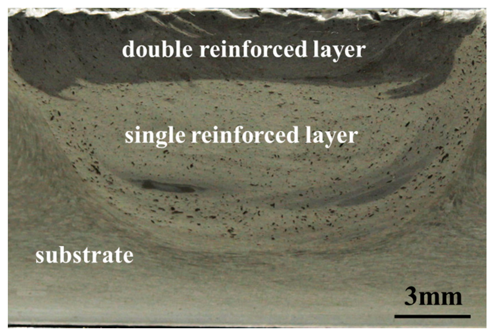
  • A double reinforcement layer of Al13Fe4 intermetallic was successfully fabricated using FSP. The volume fraction of Al13Fe4 in the double reinforced layer was higher than in the single reinforced layer. Interfaces between the double and single reinforced layer had a good metallurgical bond.
  • The particles formed in FSP specimens was mainly spherical, multilayer, bending-folding, broken, slim, and entirely intermetallic. Deformation of the particles can promote Al–Fe reaction.
  • The microhardness of the double reinforced layer was significantly increased due to the distribution of Al13Fe4 and 34CrNiMo6 particles in the reinforced layer. Compared with the AA2024 substrate, the microhardness of the double and single reinforced layers increased by five- (576 HV) and two-fold (254 HV), respectively.

Author Contributions

C.H., Y.X. and C.X. conceived and designed the experiments; Y.X. performed the experiments; C.H., F.L. provided advice in all issues; C.H., Y.X. wrote the paper; all authors were involved in writing the final paper.

Funding

This research was funded by [National Natural Science Foundation of China] grant number [51465044], [Natural Science Foundation of Jiangxi Province] grant number [20181BAB206027], [Research Project of Department of education in Jiangxi Province] grant number [GJJ160702].

Acknowledgments

The authors would like to firstly acknowledge Chunping Huang, editors and the reviewers. Acknowledgements is also extended to the people joined into this research. Furthermore, the authors would like to acknowledge the people who helped the experiments.

Conflicts of Interest

The authors declare no conflict of interest.

References

  1. Chen, L.-Y.; Xu, J.-Q.; Choi, H.; Pozuelo, M.; Ma, X.; Bhowmick, S.; Yang, J.-M.; Mathaudhu, S.; Li, X.-C. Processing and properties of magnesium containing a dense uniform dispersion of nanoparticles. Nature 2015, 528, 539–543. [Google Scholar] [CrossRef] [PubMed]
  2. Qian, J.; Li, J.; Xiong, J.; Zhang, F.; Lin, X. In situ synthesizing Al3Ni for fabrication of intermetallic-reinforced aluminum alloy composites by friction stir processing. Mater. Sci. Eng. A 2012, 550, 279–285. [Google Scholar] [CrossRef]
  3. Li, Q.; Xue, S.; Wang, J.; Shao, S.; Kwong, A.H.; Giwa, A.; Fan, Z.; Liu, Y.; Qi, Z.; Ding, J. High-Strength Nanotwinned Al Alloys with 9R Phase. Adv. Mater. 2018, 30, 1704629. [Google Scholar] [CrossRef] [PubMed]
  4. Ma, X.; Zhao, Y.; Tian, W.; Qian, Z.; Chen, H.; Wu, Y.; Liu, X. A novel Al matrix composite reinforced by nano-AlN p network. Sci. Rep. 2016, 6, 34919. [Google Scholar] [CrossRef] [PubMed]
  5. Gibson, B.T.; Lammlein, D.; Prater, T.; Longhurst, W.; Cox, C.; Ballun, M.; Dharmaraj, K.; Cook, G.; Strauss, A. Friction stir welding: Process, automation, and control. J. Manuf. Process. 2014, 16, 56–73. [Google Scholar] [CrossRef]
  6. Lotfollahi, M.; Shamanian, M.; Saatchi, A. Effect of friction stir processing on erosion–corrosion behavior of nickel–aluminum bronze. Mater. Des. 2014, 62, 282–287. [Google Scholar] [CrossRef]
  7. Kumar, A.; Raj, R.; Kailas, S.V. A novel in-situ polymer derived nano ceramic MMC by friction stir processing. Mater. Des. 2015, 85, 626–634. [Google Scholar]
  8. Gangil, N.; Maheshwari, S.; Siddiquee, A.N. Multipass FSP on AA6063-T6 Al: Strategy to fabricate surface composites. Mater. Manuf. Process. 2018, 33, 805–811. [Google Scholar] [CrossRef]
  9. Yadav, D.; Bauri, R. Processing, microstructure and mechanical properties of nickel particles embedded aluminium matrix composite. Mater. Sci. Eng. A 2011, 528, 1326–1333. [Google Scholar] [CrossRef]
  10. Najafi, A.; Movahedi, M.; Yarandi, A.S. Properties–microstructure relationship in Al–Fe in situ composite produced by friction stir processing. Proc. Inst. Mech. Eng. Part L J. Mater. Des. Appl. 2018, 233, 1955–1965. [Google Scholar] [CrossRef]
  11. Huang, G.; Hou, W.; Li, J.; Shen, Y. Development of surface composite based on Al-Cu system by friction stir processing: Evaluation of microstructure, formation mechanism and wear behavior. Surf. Coat. Technol. 2018, 344, 30–42. [Google Scholar] [CrossRef]
  12. Fujii, H.; Sun, Y.; Inada, K.; Ji, Y.; Yokoyama, Y.; Kimura, H.; Inoue, A. Fabrication of Fe-based metallic glass particle reinforced Al-based composite materials by friction stir processing. Mater. Trans. 2011, 52, 1634–1640. [Google Scholar] [CrossRef]
  13. Dinaharan, I.; Kumar, G.A.; Vijay, S.; Murugan, N. Development of Al3Ti and Al3Zr intermetallic particulate reinforced aluminum alloy AA6061 in situ composites using friction stir processing. Mater. Des. 2014, 63, 213–222. [Google Scholar] [CrossRef]
  14. Khorrami, M.S.; Kazeminezhad, M.; Kokabi, A. The effect of SiC nanoparticles on the friction stir processing of severely deformed aluminum. Mater. Sci. Eng. A 2014, 602, 110–118. [Google Scholar] [CrossRef]
  15. Saadatmand, M.; Mohandesi, J.A. Comparison between Wear Resistance of Functionally Graded and Homogenous Al-SiC Nanocomposite Produced by Friction Stir Processing (FSP). J. Mater. Eng. Perform. 2014, 23, 736–742. [Google Scholar] [CrossRef]
  16. Ni, D.; Wang, J.; Zhou, Z.; Ma, Z. Fabrication and mechanical properties of bulk NiTip/Al composites prepared by friction stir processing. J. Alloy. Compd. 2014, 586, 368–374. [Google Scholar] [CrossRef]
  17. Khorrami, M.S.; Samadi, S.; Janghorban, Z.; Movahedi, M. In-situ aluminum matrix composite produced by friction stir processing using FE particles. Mater. Sci. Eng. A 2015, 641, 380–390. [Google Scholar] [CrossRef]
  18. Song, Y.; Yang, X.; Cui, L.; Hou, X.; Shen, Z.; Xu, Y. Defect features and mechanical properties of friction stir lap welded dissimilar AA2024–AA7075 aluminum alloy sheets. Mater. Des. 2014, 55, 9–18. [Google Scholar] [CrossRef]
  19. Arora, A.; Zhang, Z.; De, A.; DebRoy, T. Strains and strain rates during friction stir welding. Scr. Mater. 2009, 61, 863–866. [Google Scholar] [CrossRef]
  20. Ammouri, A.; Kridli, G.; Ayoub, G.; Hamade, R. Relating grain size to the Zener–Hollomon parameter for twin-roll-cast AZ31B alloy refined by friction stir processing. J. Mater. Process. Technol. 2015, 222, 301–306. [Google Scholar] [CrossRef]
  21. Morisada, Y.; Imaizumi, T.; Fujii, H. Determination of strain rate in friction stir welding by three-dimensional visualization of material flow using X-ray radiography. Scr. Mater. 2015, 106, 57–60. [Google Scholar] [CrossRef]
  22. Davis, J. ASM International: Handbook of Aluminium & Aluminium Alloys; ASM International: Novelty, OH, USA, 1996. [Google Scholar]
  23. El-Danaf, E.A.; El-Rayes, M.M.; Soliman, M.S. Friction stir processing: An effective technique to refine grain structure and enhance ductility. Mater. Des. 2010, 31, 1231–1236. [Google Scholar] [CrossRef]
  24. Lee, I.; Kao, P.; Ho, N. Microstructure and mechanical properties of Al–Fe in situ nanocomposite produced by friction stir processing. Intermetallics 2008, 16, 1104–1108. [Google Scholar] [CrossRef]
  25. Massalski, T.B. Binary Alloy Phase Diagrams; ASM International: Novelty, OH, USA, 1992; p. 147. [Google Scholar]
Figure 1. Scanning electron microscopy (SEM) image of the as-received commercial 34CrNiMo6 particles.
Metals 09 01002 g001
Figure 2. Optical micrograph of the surface microstructure of AA2024 aluminum.
Metals 09 01002 g002
Figure 3. Tools used in this experiment: (a) tool A and (b) tool B.
Metals 09 01002 g003
Figure 4. Schematic diagram of two reinforced layers of Al–Fe intermetallic composites prepared via friction stir processing (FSP).
Metals 09 01002 g004
Figure 5. Macro image of the two reinforced layers.
Metals 09 01002 g005
Figure 6. The SEM microstructure of the two reinforced layers and the interface.
Metals 09 01002 g006
Figure 7. X-ray diffraction (XRD) results of the two reinforced layers: (a) double reinforced layer and (b) single reinforced layer.
Metals 09 01002 g007aMetals 09 01002 g007b
Figure 8. The optical microscopy (OM) microstructure of the two reinforced layers: (a) the double reinforced layer, (b) the interface between the double and single reinforced layers (the enlarged micrograph marked B), (c) white particles in the double reinforced layer (the enlarged micrograph marked A), and (d) the single reinforced layer.
Metals 09 01002 g008
Figure 9. The morphology of 34CrNiMo6 particles in the two reinforced layers: (a) spherical, (b) multilayer, (c) bending-folding, (d) broken, (e) slim, and (f) completely intermetallic.
Metals 09 01002 g009aMetals 09 01002 g009b
Figure 10. The SEM microstructure of 34CrNiMo6 particles and the intermetallic layer: (a,b) the thickness of the intermetallic layer and (c) a thin layer exists between the slim 34CrNiMo6 particles and Al13Fe4 (the enlarged micrograph marked C in (b)).
Metals 09 01002 g010
Figure 11. The energy dispersive spectroscopy (EDS) of typical slim 34CrNiMo6 particles and its surrounding region.
Metals 09 01002 g011
Figure 12. Al-Fe phase diagram [25].
Metals 09 01002 g012
Figure 13. Microhardness of the two reinforced layers: (a) double reinforced layer and (b) single reinforced layer.
Metals 09 01002 g013
Table 1. The chemical composition of the AA2024 aluminum plate (wt.%).
SiFeCuMnMgNiZnTiAl
0.50.53.8–4.90.3–0.91.2–1.80.10.250.15balance
Table 2. The thickness of intermetallic of different regions corresponding to Figure 9 and Figure 10.
RegionL/WThickness (μm)
A117
B1617.5
B27.221
B31226
Table 3. The average chemical compositions of different regions corresponding to Figure 11 analyzed by EDS (at.%).
Element12345
Al76.175.2092.190.5
Fe22.820.595.91.92.7
Cr--1.4--
Ni-1.11.5--
Si-0.80.30.70.5
Cu0.71.9-3.84.4
Mn--0.9-0.6
Mg0.40.5-1.51.3

