Effect of Tool Rotational Speed on the Microstructure and Mechanical Properties of Bobbin Tool Friction Stir Welded 6082-T6 Aluminum Alloy

Abstract
:1. Introduction
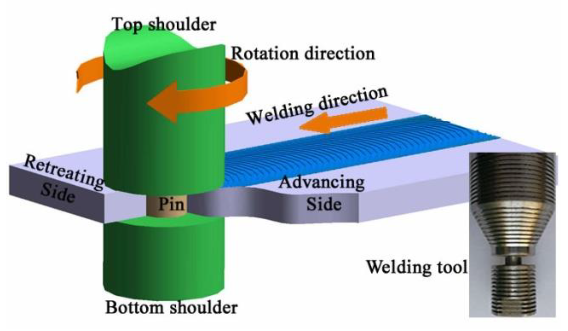
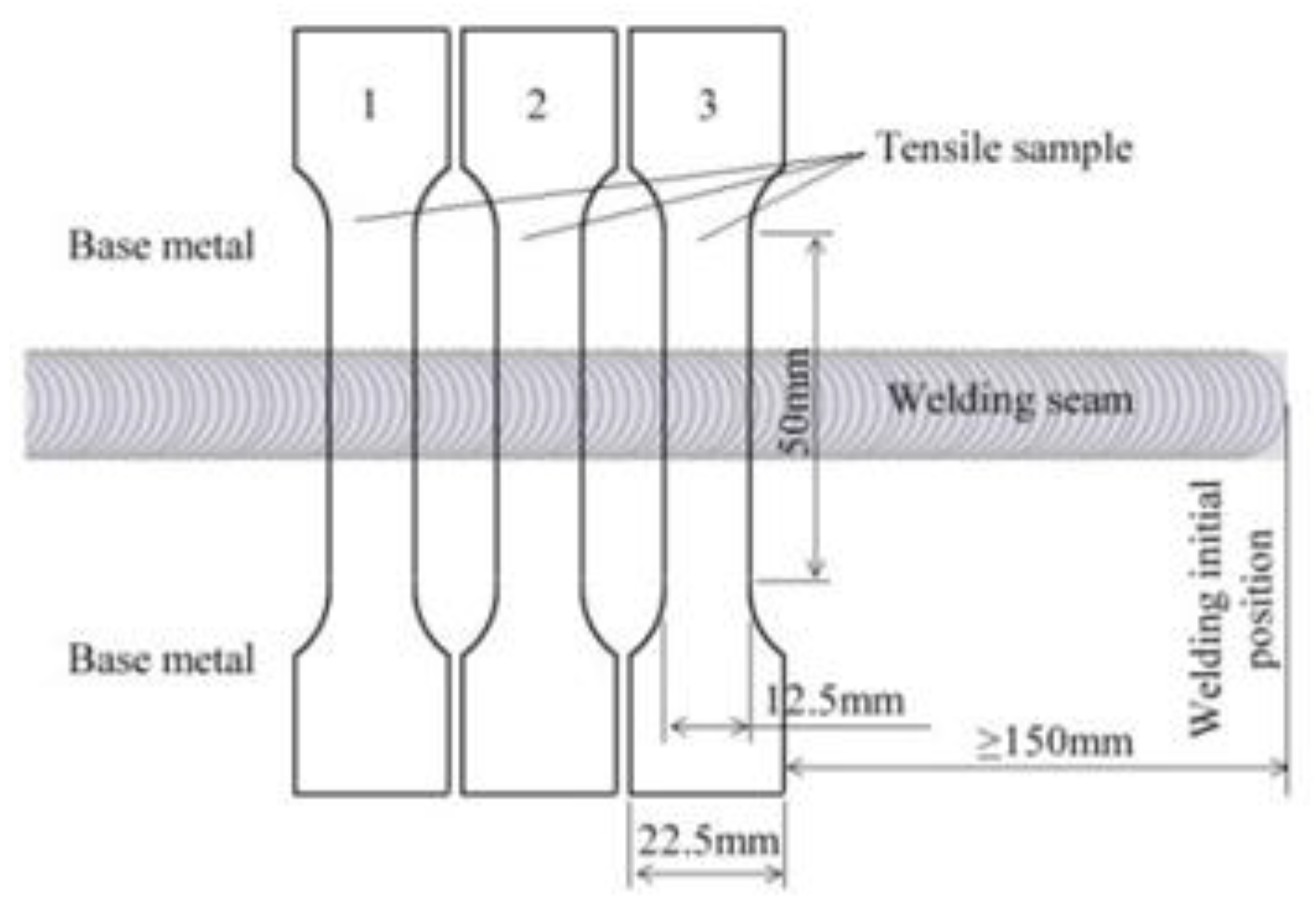
2. Materials and Methods
3. Results
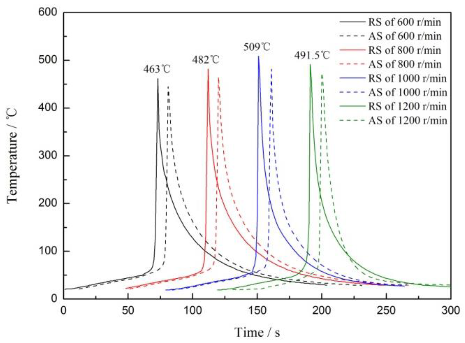
3.1. Welding Thermal Cycles
3.2. Microstructure of the Joints
3.3. Mechanical Properties of the Joints
4. Conclusions
- The maximum temperature at the joint increases first and then decreases with increasing rotational speed, reaching a maximum temperature of 509 °C at 1000 r/min. The maximum temperature at the RS of the joints is higher than the AS, and the temperature difference is approximately 20 °C.
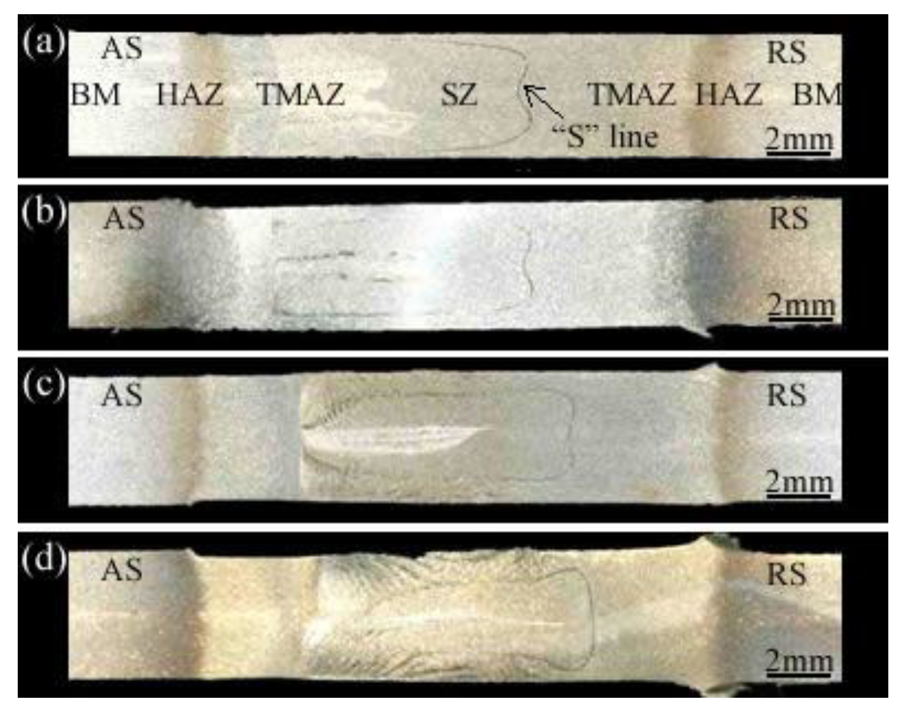
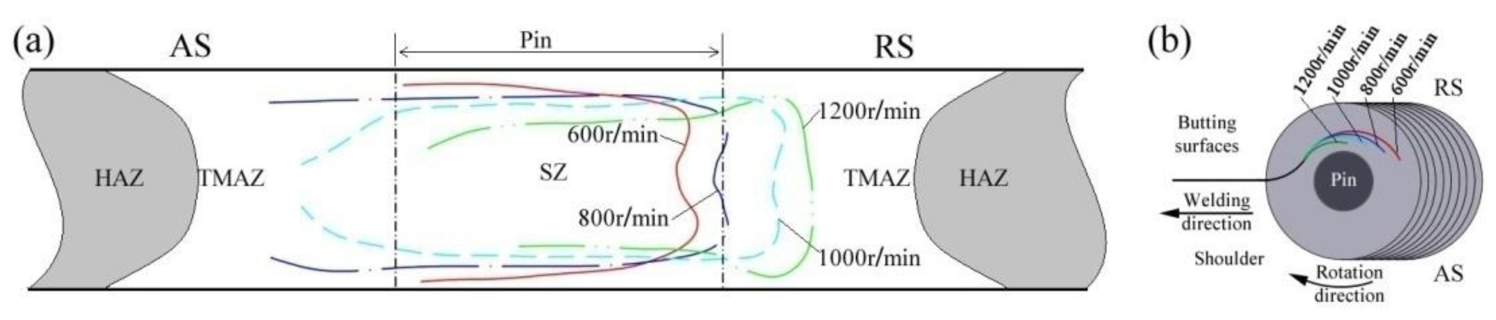
- The macromorphology of the cross-section of the joint is rectangular, and an “S” line and gray-white texture can be observed. The “S” line is an opposite “C” shape, and the opening is on the AS side. With increasing welding speed, the “S” line is elongated and narrowed.
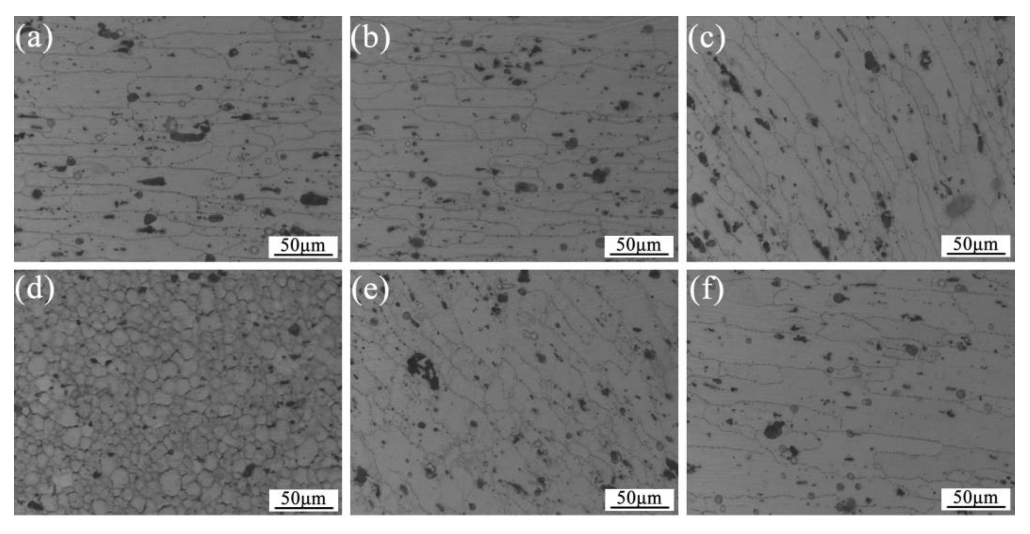
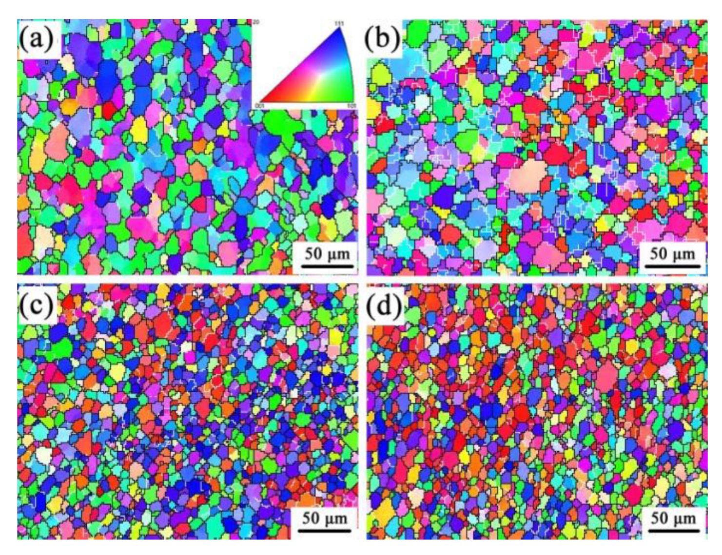
- In the welded joint, the SZ has much smaller equiaxed recrystallized grains, and the TMAZ are elongated to form bending and elongated grains. In the HAZ, some grains are recrystallized and have a better grain size uniformity based on the rolling morphologies of BM. With increasing welding speed, the average grain size in the SZ region decreases from 9.1 micron to 7.1 micron.
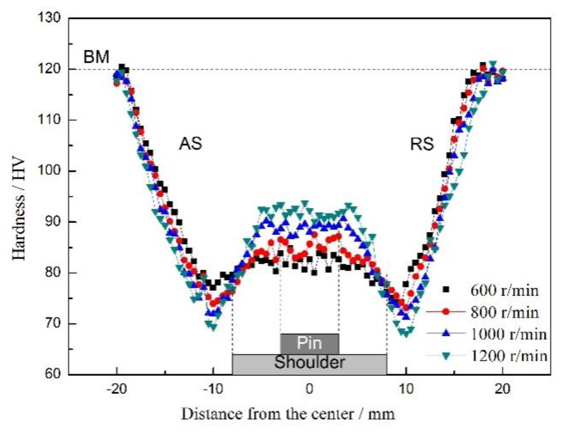
- The joints present a W-shaped hardness profile along their cross-section. The minimum hardness appears in the HAZ and is HV 68–74, rising to HV 80–94 at the center of the SZ. When the rotational speed increases from 600 r/min to 1200 r/min, the hardness of HAZ decreases gradually, and the hardness of SZ increases.
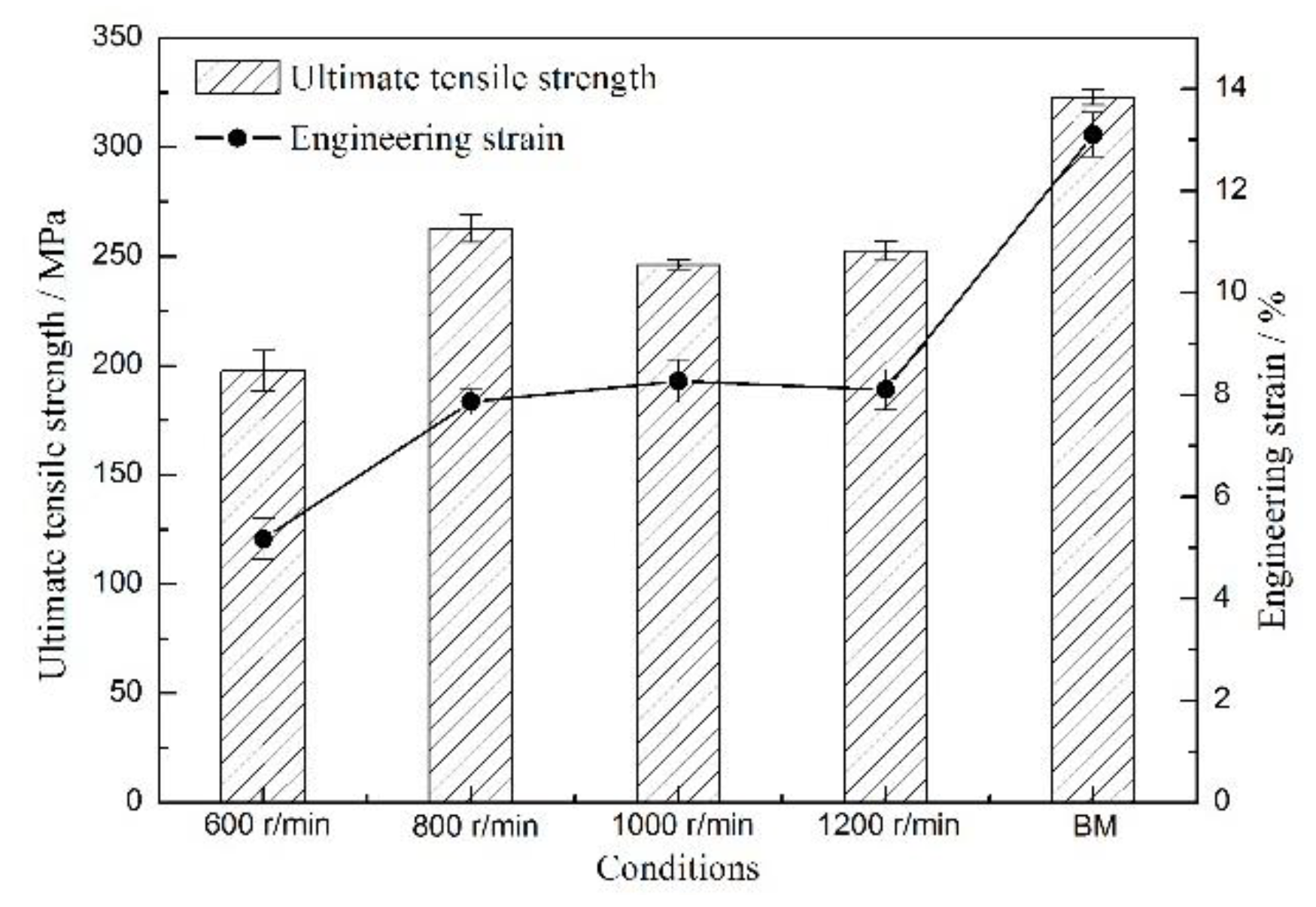
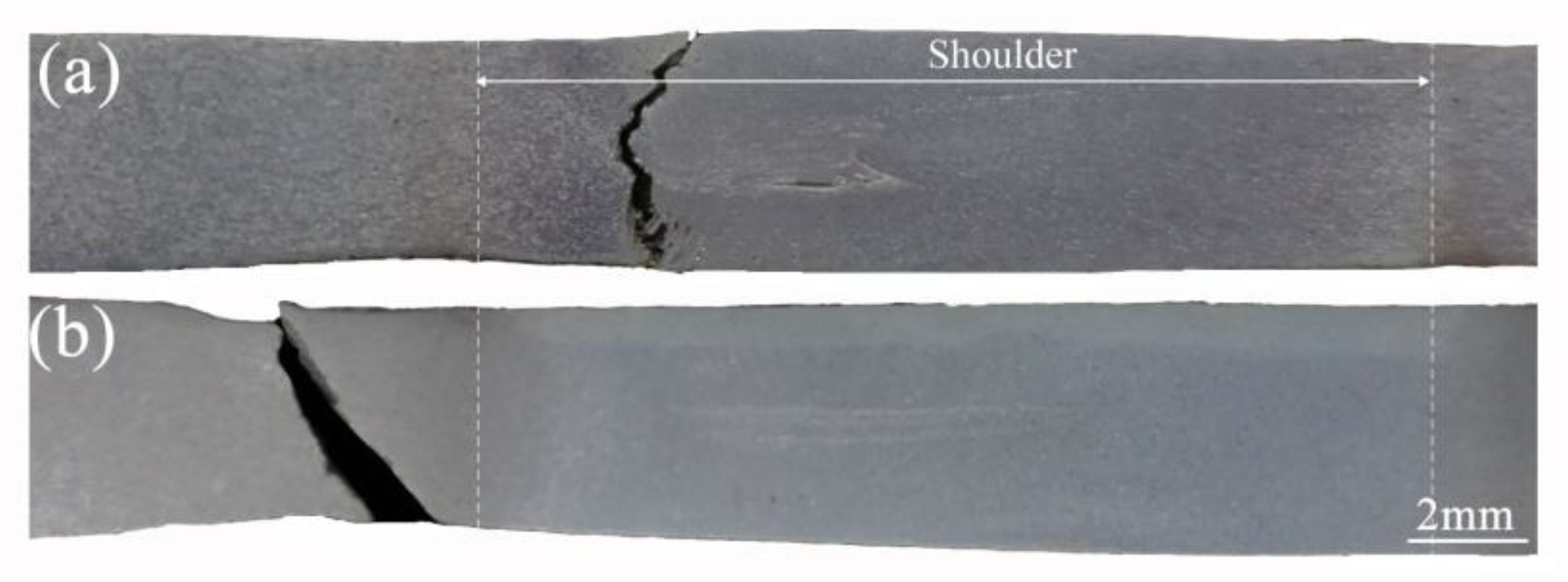
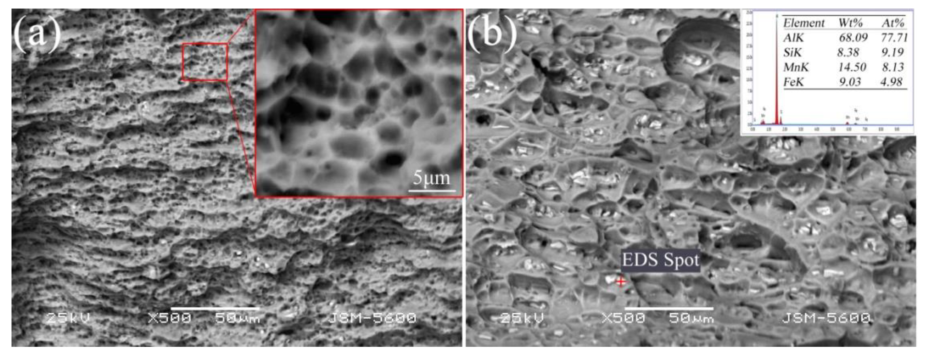
- When the rotational speed is 600 r/min, the strength is the lowest. The fracture location between SZ and TMAZ. When the rotational speed is increased, the fracture location is all in HAZ, and the fracture surface is dimple-like. The ultimate tensile strength significantly increases and reaches a maximum (262.7 MPa) at 800 r/min; the engineering strain is 7.9%.
Author Contributions
Funding
Conflicts of Interest
References
- Thomas, W. Friction Stir Welding. International Patent Application No PCT/GB92/02203, 6 December 1991. [Google Scholar]
- Dialami, N.; Cervera, M.; Chiumenti, M. Effect of the tool tilt angle on the heat generation and the material flow in friction stir welding. Metals 2019, 9, 28. [Google Scholar] [CrossRef]
- Hamilton, C.; Dymek, S.; Kopyscianski, M.; Weglowska, A.; Pietras, A. Numerically based phase transformation maps for dissimilar aluminum alloys joined by friction stir-welding. Metals 2018, 8, 324. [Google Scholar] [CrossRef]
- Nandan, R.; DebRoy, T.; Bhadeshia, H.K.D.H. Recent advances in friction-stir welding–Process, weldment structure and properties. Prog. Mater. Sci. 2008, 53, 980–1023. [Google Scholar] [CrossRef]
- Hamilton, C.; Dymek, S.; Sommers, A. Characteristic temperature curves for aluminum alloys during friction stir welding. Weld. J. 2010, 89, 189–194. [Google Scholar]
- Bussu, G.; Irving, P.E. The role of residual stress and heat affected zone properties on fatigue crack propagation in friction stir welded 2024-T351 aluminium joints. Int. J. Fatigue 2003, 25, 77–88. [Google Scholar] [CrossRef]
- Threadgill, P.L.; Ahmed, M.M.Z.; Martin, J.P.; Perrett, J.G.; Wynne, B.P. The use of bobbin tools for friction stir welding of aluminium alloys. Mater. Sci. Forum 2010, 638–642, 1179–1184. [Google Scholar] [CrossRef]
- Huang, Y.X.; Wan, L.; Lv, S.X.; Feng, J.C. Novel design of tool for joining hollow extrusion by friction stir welding. Sci. Technol. Weld. Joining 2013, 18, 239–246. [Google Scholar] [CrossRef]
- Li, J.Y.; Zhou, X.P.; Dong, C.L.; Dong, J.H. Temperature fields in 6082 aluminum alloy samples bobbin-tool friction stir welded. J. Aeronaut. Mater. 2013, 33, 36–40. [Google Scholar]
- Liu, X.M.; Yao, J.S.; Cai, Y.; Meng, H.; Zou, Z.D. Simulation on the temperature field of bobbin tool friction stir welding of AA 2014 aluminium alloy. Appl. Mech. Mater. 2013, 433–435, 2091–2095. [Google Scholar] [CrossRef]
- Chen, S.J.; Li, H.; Lu, S.; Ni, R.Y.; Dong, J.H. Temperature measurement and control of bobbin tool friction stir welding. Int. J. Adv. Manuf. Technol. 2016, 86, 337–346. [Google Scholar] [CrossRef]
- Wan, L.; Huang, Y.X.; Lv, Z.L.; Lv, S.X.; Feng, J.C. Effect of self-support friction stir welding on microstructure and microhardness of 6082–T6 aluminum alloy joint. Mater. Des. 2014, 55, 197–203. [Google Scholar] [CrossRef]
- Li, Y.P.; Sun, D.Q.; Gong, W.B.; Liu, L. Effects of postweld aging on the microstructure and properties of bobbin tool friction stir-welded 6082-T6 aluminum alloy. Int. J. Miner. Metall. Mater. 2019, 26, 849–857. [Google Scholar] [CrossRef]
- Dong, J.H.; Gao, C.; Lu, Y.; Han, J.; Jiao, X.D.; Zhu, Z.X. Microstructural characteristics and mechanical properties of bobbin-tool friction stir welded 2024-T3 aluminum alloy. Int. J. Miner. Metall. Mater. 2017, 24, 171–178. [Google Scholar] [CrossRef]
- Okamoto, K.; Sato, A.; Park, S.H.; Hirano, S. Microstructure and Mechanical Properties of FSWed Aluminum Extrusion with Bobbin Tools. Mater. Sci. Forum 2012, 706–709, 990–995. [Google Scholar] [CrossRef]
- Mahmoud, T.S.; Gaafer, A.M.; Khalifa, T.A. Effect of tool rotational and welding speeds on microstructural and mechanical characteristics of friction stir welded A319 cast Al alloy. Metal. Sci. J. 2008, 24, 553–559. [Google Scholar] [CrossRef]
- Li, W.Y.; Fu, T.; Hütsch, L.; Hilgert, J.; Wang, F.F.; dos Santos, J.F.; Huber, N. Effects of tool rotational and welding speed on microstructure and mechanical properties of bobbin-tool friction-stir welded Mg AZ 31. Mater. Des. 2014, 64, 714–720. [Google Scholar]
- Wang, F.F.; Li, W.Y.; Shen, J.J.; Hu, S.Y.; Dos Santos, J.F. Effect of tool rotational speed on the microstructure and mechanical properties of bobbin tool friction stir welding of Al–Li alloy. Mater. Des. 2015, 86, 933–940. [Google Scholar] [CrossRef]
- Liu, H.J.; Hou, J.C.; Guo, H. Effect of welding speed on microstructure and mechanical properties of self-reacting friction stir welded 6061-T6 aluminum alloy. Mater. Des. 2013, 50, 872–878. [Google Scholar] [CrossRef]
- Zhang, H.J.; Wang, M.; Zhang, X.; Yang, G.X. Microstructural characteristics and mechanical properties of bobbin tool friction stir welded 2A14-T6 aluminum alloy. Mater. Des. 2015, 65, 559–566. [Google Scholar] [CrossRef]
- Wang, F.F.; Li, W.Y.; Shen, J.; Wen, Q.; dos Santos, J.F. Improving weld formability by a novel dual-rotation bobbin tool friction stir welding. J. Mater. Sci. Technol. 2018, 34, 135–139. [Google Scholar] [CrossRef]
- Zhao, S.; Bi, Q.Z.; Wang, Y.H.; Shi, J. Empirical modeling for the effects of welding factors on tensile properties of bobbin tool friction stir-welded 2219-T87 aluminum alloy. Int. J. Adv. Manuf. Technol. 2018, 90, 1105–1118. [Google Scholar] [CrossRef]
- ASTM E8/E8M-13a. Standard Test Methods for Tension Testing of Metallic Materials; ASTM International: West Conshohocken, PA, USA, 2013. [Google Scholar]
- Sato, Y.S.; Takauchi, H.; Park, S.H.C.; Kokawa, H. Characteristics of the kissing-bond in friction stir welded Al alloy 1050. Mater. Sci. Eng. A 2005, 405, 333–338. [Google Scholar] [CrossRef]
- Zhang, Z.; Xiao, B.L.; Ma, Z.Y. Effect of segregation of secondary phase particles and “S” line on tensile fracture behavior of friction stir-welded 2024Al-T351 joints. Metall. Mater. Trans. A 2013, 44A, 4081–4097. [Google Scholar] [CrossRef]
- Su, J.Q.; Nelson, T.W.; Sering, C.J. Microstructure evolution during FSW/FSP of high strength aluminum alloys. Mater. Sci. Eng. A 2005, 405, 277–286. [Google Scholar] [CrossRef]
- Dong, P. Study on microstructures and properties of friction stir welding joints of 6005A-T6 aluminum alloy. Ph.D. Thesis, Jilin University, Changchun, China, 4 June 2014. [Google Scholar]


| Chemical Composition (wt%) | Mechanical Properties | ||||||||||
|---|---|---|---|---|---|---|---|---|---|---|---|
| Si | Fe | Cu | Mn | Mg | Cr | Zn | Ti | Al | Tensile Strength | Yield Strength | Elongation |
| 0.97 | 0.50 | 0.10 | 0.7 | 1.02 | 0.25 | 0.20 | 0.10 | Bal | 323 MPa | 272 MPa | 13% |
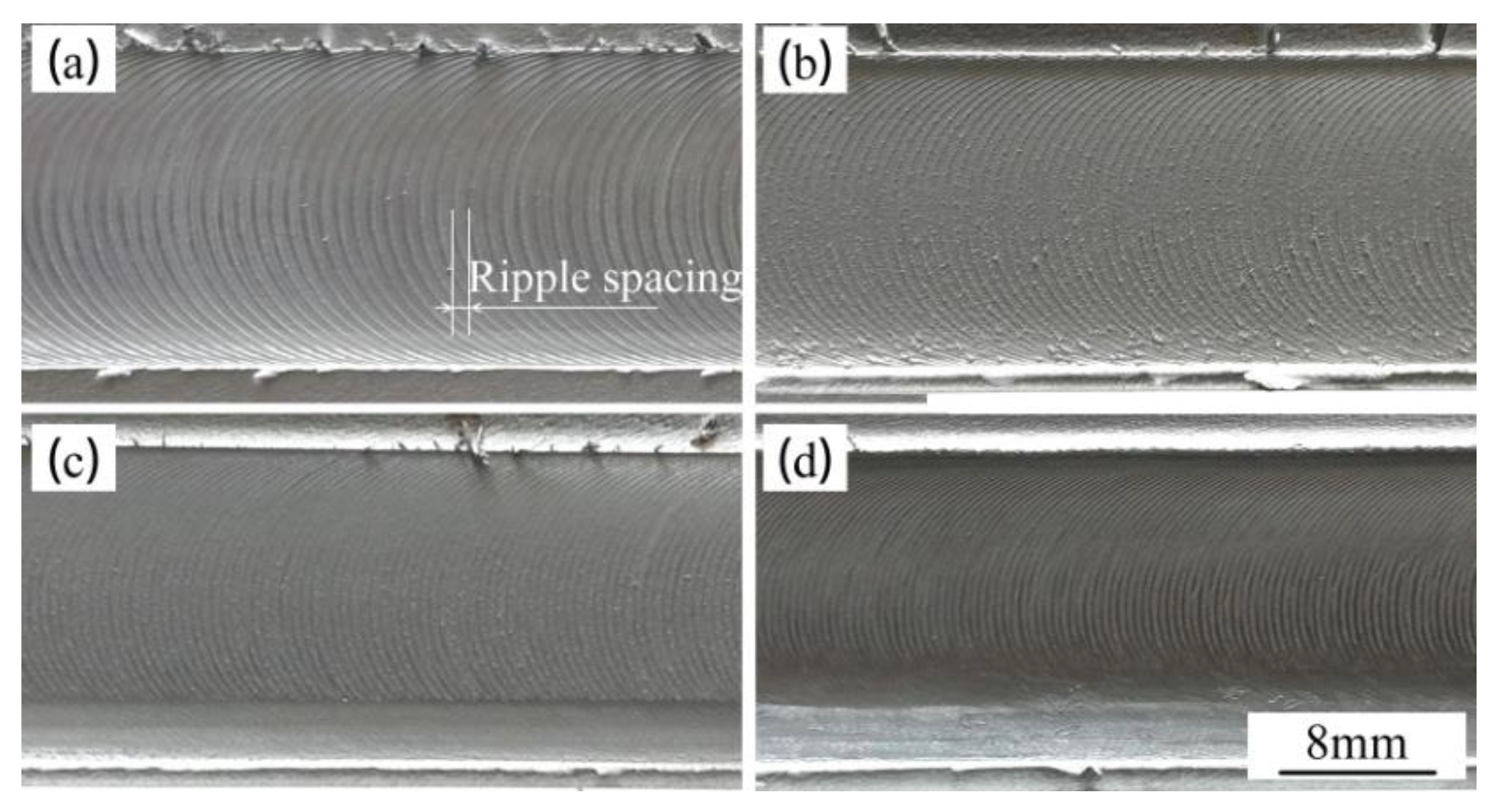
| No. | Welding Speed (mm/min) | Rotational Speed (r/min) | Distance of Ripple (mm) | The Distance Per Revolution of the Tool (mm) |
|---|---|---|---|---|
| 1 | 500 | 600 | 0.82 | 0.833 |
| 2 | 500 | 800 | 0.61 | 0.625 |
| 3 | 500 | 1000 | 0.5 | 0.5 |
| 4 | 500 | 1200 | 0.41 | 0.417 |
| Rotation Speed (r/min) | Average Grain Size/μm |
|---|---|
| 600 | 9.1 |
| 800 | 8.5 |
| 1000 | 7.4 |
| 1200 | 7.1 |
© 2019 by the authors. Licensee MDPI, Basel, Switzerland. This article is an open access article distributed under the terms and conditions of the Creative Commons Attribution (CC BY) license (http://creativecommons.org/licenses/by/4.0/).
Share and Cite
Li, Y.; Sun, D.; Gong, W. Effect of Tool Rotational Speed on the Microstructure and Mechanical Properties of Bobbin Tool Friction Stir Welded 6082-T6 Aluminum Alloy. Metals 2019, 9, 894. https://doi.org/10.3390/met9080894
Li Y, Sun D, Gong W. Effect of Tool Rotational Speed on the Microstructure and Mechanical Properties of Bobbin Tool Friction Stir Welded 6082-T6 Aluminum Alloy. Metals. 2019; 9(8):894. https://doi.org/10.3390/met9080894
Chicago/Turabian StyleLi, Yupeng, Daqian Sun, and Wenbiao Gong. 2019. "Effect of Tool Rotational Speed on the Microstructure and Mechanical Properties of Bobbin Tool Friction Stir Welded 6082-T6 Aluminum Alloy" Metals 9, no. 8: 894. https://doi.org/10.3390/met9080894