Article

Failure-Analysis Based Redesign of Furnace Conveyor System Components: A Case Study

by
Beatriz González-Ciordia
1,2,
Borja Fernández
1,2,
Garikoitz Artola
3,
Maider Muro
3,
Ángel Sanz
4 and
Luis Norberto López de Lacalle
2,*
1
Gestamp ES&AM, AIC-Automotive Intelligence Center, Barrio Boroa, 2, 483401 Amorebieta-Etxano, Spain
2
Department of Mechanical Engineering, University of the Basque Country (UPV/EHU), Plaza Ingeniero Torres Quevedo 1, 48013 Bilbao, Spain
3
Fundación Azterlan, Aliendalde Auzunea 6, 48200 Durango, Spain
4
GHI Hornos Industriales, Aperribai 4, 48960 Galdakao, Spain
*
Author to whom correspondence should be addressed.
Metals 2019, 9(8), 816; https://doi.org/10.3390/met9080816
Submission received: 17 June 2019 / Revised: 16 July 2019 / Accepted: 20 July 2019 / Published: 25 July 2019
(This article belongs to the Special Issue Failure Mechanisms in Alloys)

Abstract

:
Any manufacturing equipment designed from scratch requires a detailed follow-up of the performance for the first units placed in service during the production ramp-up, so that lessons learned are immediately implemented in next deliveries and running equipment is accordingly updated. Component failure analysis is one of the most valuable sources of improvement among these lessons. In this context, a failure-assessment based design revision of the conveying system of a newly developed press hardening furnace is presented. The proposed method starts with a forensic metallurgical analysis of the failed components, followed by an investigation of the working conditions to ensure they match the forensic observations. The results of this approach evidenced an initially unforeseen thermo-mechanical damage produced by a combination of thermal distortions, material ageing, and mechanical fatigue. Once the cause–effect relationship for the failure is backed up by evidence, an improved design is proposed. As a conclusion, a new standard design for the furnace entrance set of rollers in hot stamping lines was established for roller hearth furnaces. The solution can be extended to similar applications, ensuring the same issues will not arise thanks to the lessons learned.

Graphical Abstract

1. Introduction

Press hardening is a fast-growing technology, mainly exploited for the safety and weight improvements that it introduces in the automotive industry [1,2,3]. Austenitizing the steel to be hardened is a must in the manufacturing process, which turns the austenitizing furnace into a key piece of equipment. Despite that several heating alternatives have been studied, such as resistance heating [4], induction heating [5,6], or direct contact heating [7], radiant heating is the leading industrial solution for mass production. The amount of published works related to dedicated furnaces for press hardening is, though, scarce and mostly focused on roller hearth furnaces [8].
Roller hearth furnaces carry the steel sheet blanks through the furnace by means of ceramic rollers that stand the nominal working temperatures required for press hardening furnaces, which range from 890 °C to 950 °C. These ceramic rollers can show a variety of porosity levels and chemical compositions, ranging from high density fused silica to very porous aluminosilicates. The main drawback of this conveying system lies in the brittle nature of the ceramics and its impact in furnace maintenance costs and production dead-times arising from for broken roller replacement. These maintenance requirements are increased by the predominance AlSi coated steel sheet in the press hardened products. The AlSi coating damages the ceramics rollers in two ways (Figure 1):
-
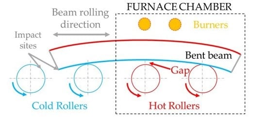
It can partially melt and adhere to the roll, generating a build-up that leads to format trajectory deviation inside the furnace. Therefore, the formats do not exit the furnace in a proper position for robotic transferring to the stamping press.
-
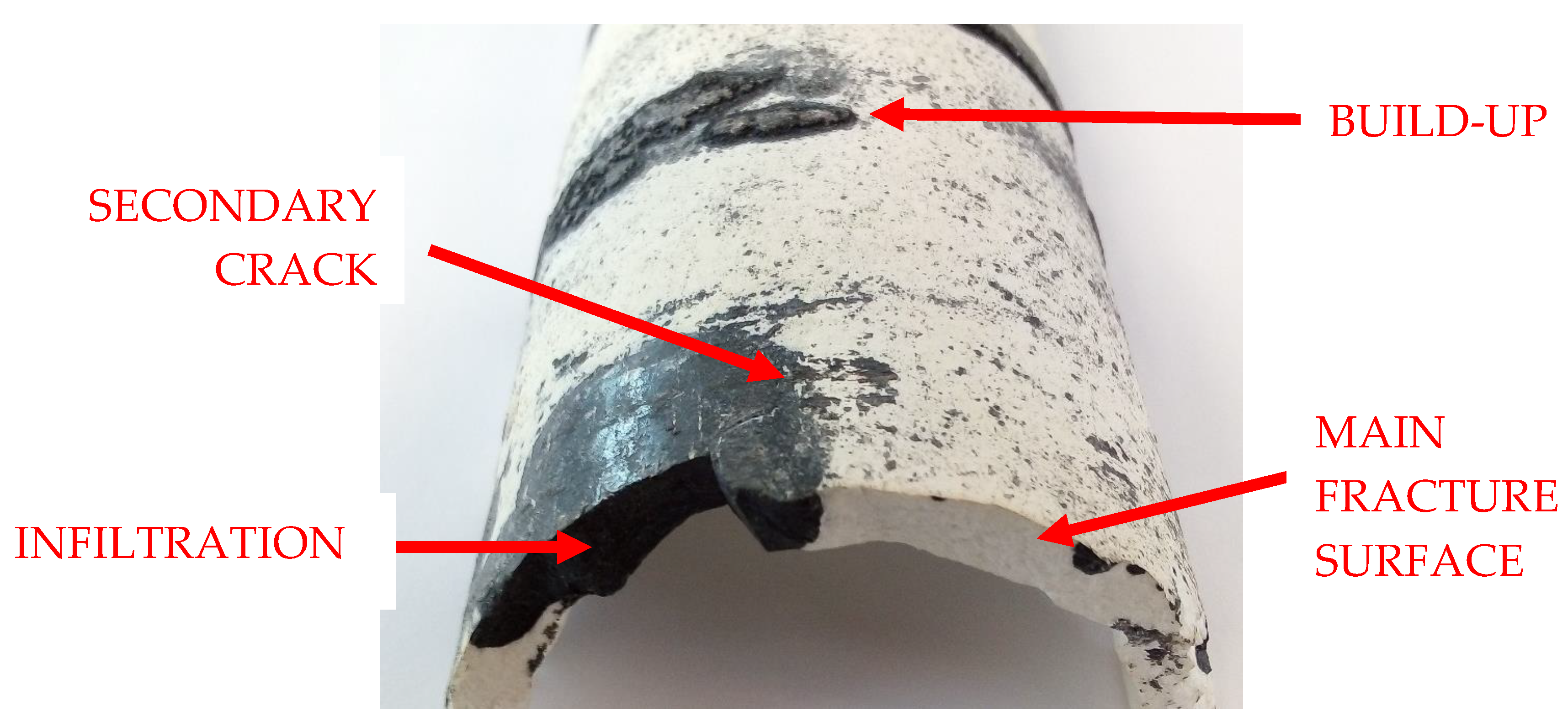
The molten AlSi can infiltrate in the pores and micro-cracks in the roll surfaces. When the furnace is cooled down for a stop or an energy saving condition, such as a weekend stand-by, the infiltrated metal solidifies and acts as a wedge, which leads to roller fracture.
The rolling beam sheet blank conveying concept is an advantageous alternative to the roller hearth furnace system as it allows avoiding these two issues. More specifically, the rolling beam design overcomes the limitations imposed by the roller hearth thanks to the following improvements [9]:
-
Blanks can be loaded widthwise, leading to shorter production lines.
-
Transport system-to-blank contact is reduced, minimizing conveying system contamination problems due to AlSi coating melting.
-
Blank location accuracy at the exit point of the blanks from the furnace is improved as a result of the fixed stroke of the rolling beams.
-
Overall equipment efficiency is increased owing to lower maintenance needs and less stops are needed for correcting blank positioning at the furnace exit.
On the drawback side, roller hearth furnaces are a mature option for austenitizing that have worked successfully for years in press hardening, while roller beam furnaces have been in use for less than five years now. As the novel roller beam sheet metal format conveying system was designed from scratch, close follow-up of the furnaces deployed first is a must to ensure a quick maturation of the equipment. During this sort of follow-up, component failure analysis has proven to be a source of major information to introduce design and operation improvements in many applications [10,11,12]. In the specific case of the furnaces, studies on elements such as radiant tubes [13], internal supports [14], gas conductions [15], and product transportation systems [16] are representative examples.
In the following sections, a failure analysis-based improvement of the steel rollers in the conveying system of a roller beam press hardening furnace is presented. These rollers are the elements transmitting movement from the drives to the beams that convey the blanks inside the furnace. After an operating time of 1800 h at a nominal temperature of 930 °C, a roller from the front section of the furnace (initial 2 m of the chamber) failed in the fillet between the end bell and the journal that connected the roller to the drive (Figure 2a). The fillet fractured across the diameter where it met the journal and showed clear fatigue marks (Figure 2b).
The journal, end-bell, and fillet design criteria followed the furnace maker’s standard, which was backed-up by successful experiences with components that were predicted to show analogous working conditions in other types of furnaces and should fail due to creep. More specifically, the applied criteria for design was a maximum 1% creep after 100,000 h under operating conditions. This was translated to a maximum working stress of 125 MPa for the failure site [17]. This case study focuses on determining the root causes behind the failure of only 2 rollers out of the 36 identical rollers that were installed in the furnace and in redesigning the conveying system to mature the robustness of the equipment.

2. Materials and Methods

The studied rollers were built in the stainless-steel grade AISI 304 and were comprised by two bell and journal ends (Figure 3), welded to a cylindrical body (tube) that crossed the entire furnace chamber width. The tube ends were welded to the Ø180 mm of the conical bells. One of the journals was fit into a bearing adapted to accommodate the roller expansion during furnace warm-up, while the other was fixed to the motor that applied the thrust movements involved in rolling beam format conveying.
The materials employed for the study corresponded to two rollers (identified as BR1 and BR2) that were found collapsed during furnace maintenance stops, both showing the fracture in the motor side journal (Figure 4). Both rollers were in the first section of the furnace, where the formats enter the austenitizing chamber. Following the detection of the two broken rollers, all journal fillet radiuses, both motor side and expansion side, were penetrant dye inspected for the presence of cracks in all the rollers of the furnace. Despite no cracks being detected, five rolls were randomly selected and disassembled from the furnace to confirm the absence of cracks in the fillets by metallographic cross sectioning and the absence of cracking was confirmed. The failure was thus specific to the two affected rollers, which were studied more in depth.
The failure analysis on the cracked rollers was performed in the following steps:
  • Metallurgical analysis of the fractured component and proposal of the failure mechanism.
    • Chemical analysis to verify that the material was correctly supplied.
    • Tensile testing of a specimen from the area of the journal that works the coldest in service, to ensure there was not an initial mechanical property problem from the beginning.
    • Microstructural inspection in the neighborhood of the fracture and in a position far from the fracture (cold area), to check the phase evolution of the material during service in the cracked area compared with a section thermally unaltered in service.
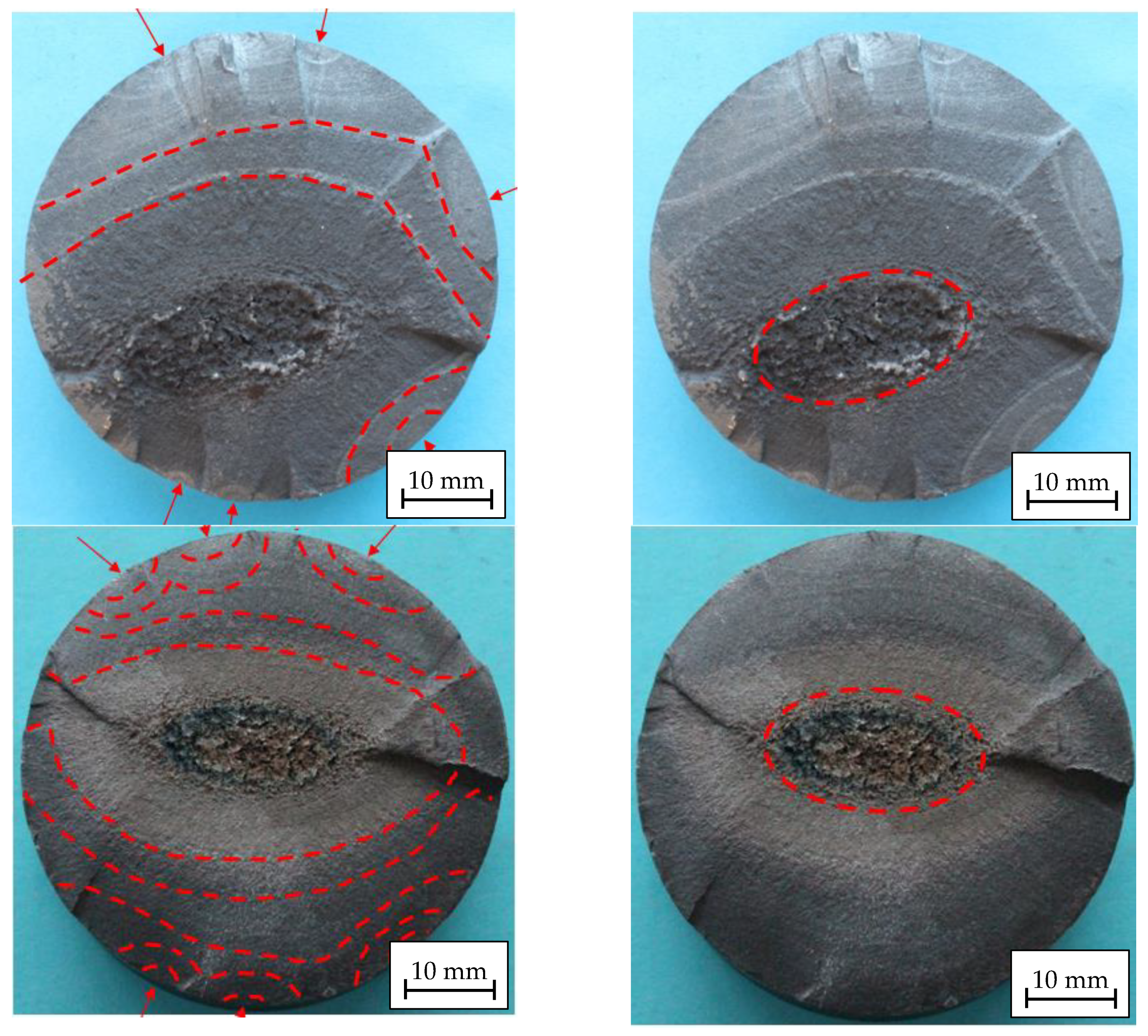
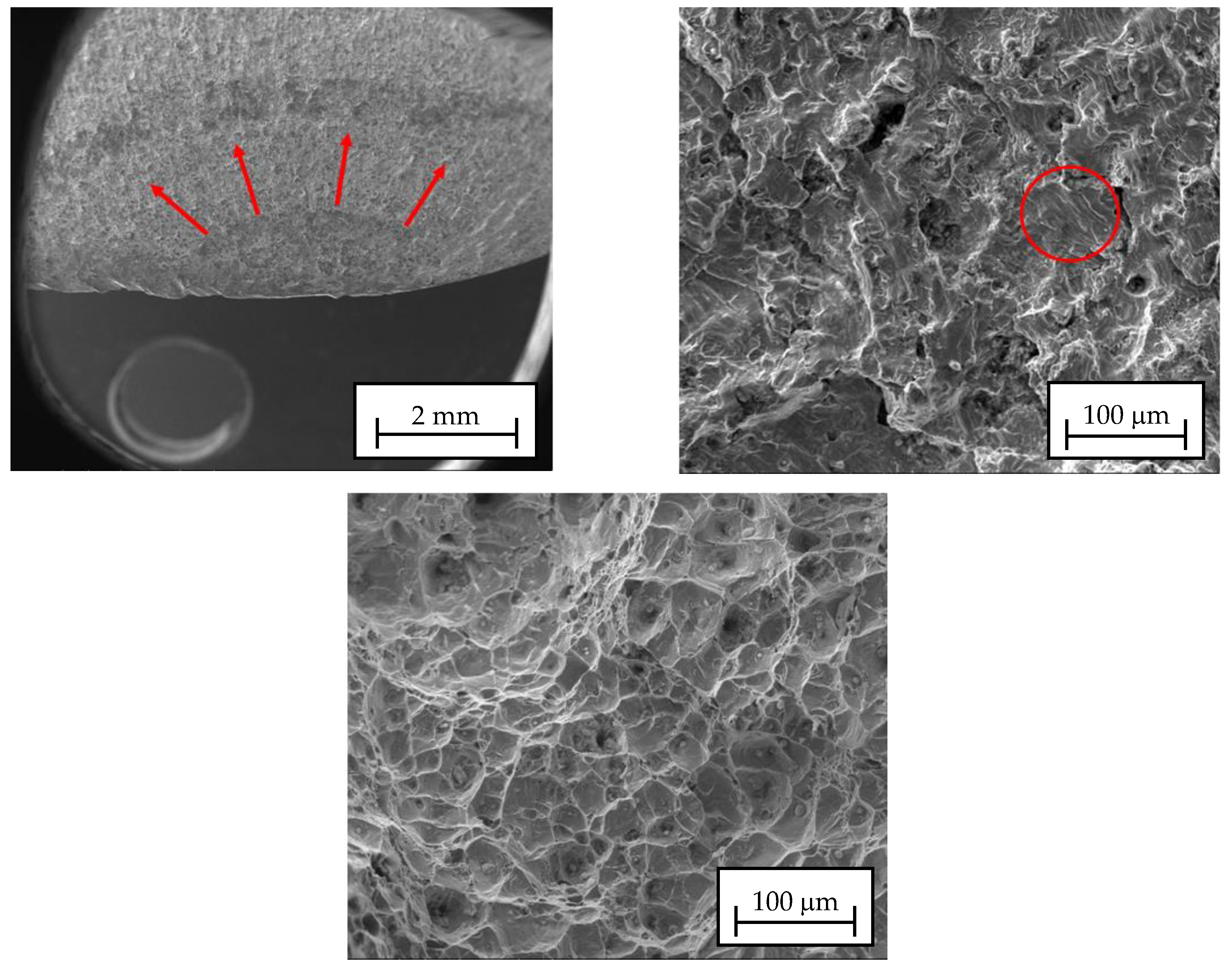
    • Fractographic inspection of the fracture surface to determine the nature of the damage that the roll suffered and its trajectory.
    • Verification of the concordance of the observations against the expected failure mode by design of the roller.
  • Investigation of the deviations between the expected working conditions and the actual working conditions of the rolls that would fit with the failure mechanism.
    • In situ measurement of the temperature in the failure site with the furnace running.
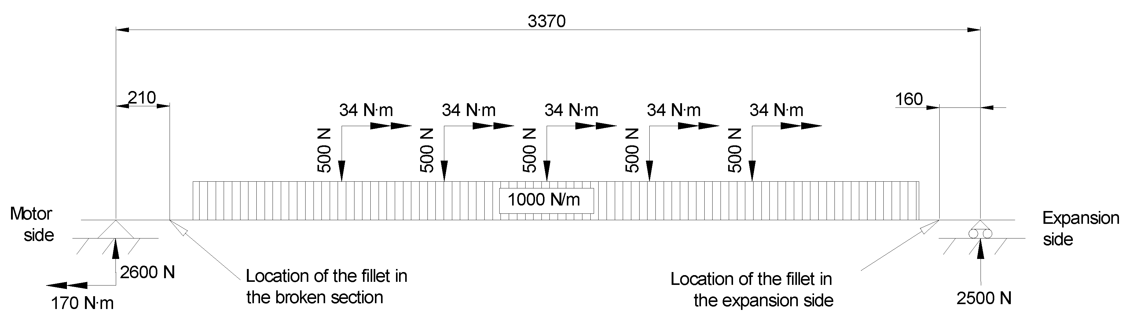
    • Verification of the stress in the failure site by studying the load profile during the movement sequence in the running furnace.
    • Proposal of the failure mechanism taking into account the deviations of the actual working condition from the loads and temperatures expected from design.
  • Redesign of the roll to avoid future failures.

3. Results and Discussion

3.1. Metallurgical Analyses

Starting with the verification of the chemical composition, it was performed by employing spark emission spectrometry (Spectrolab + Spark Analyzer Vision V2, Model M10; Spectro Analytical Instruments GmbH, Boschstr. 10, Kleve, Germany). This allowed evaluating whether or not there was any mistake in the material supply in terms of satisfying the roller drawing indications. Table 1 shows that there was no unexpected deviation on the materials, and they agreed on the AISI 304 that was chosen by design.
Room temperature tensile properties were also checked following the work of [19] in a 100 kN universal testing machine (Zwick Z100, ZwickRoell GmbH & Co. KG, Ulm, Germany) to validate that the material was in a proper mechanical condition when the component was installed. Ø10 mm cylindrical specimens were machined from the coldest end of the journal. This location was chosen to ensure that the was no thermal modification in the material because of the time the roller spent in service. The results are shown in Table 2 and allow discarding the presence of intrinsically faulty raw material, as the purchasing specifications were met.
The metallographic analyses of the materials were performed by means of light microscopy (Leica Microsystems, Wetzlar, Germany). The inspections showed that the fracture area was submitted to high temperatures, in excess of 550 °C, as extensive sigma phase evolution and intergranular carbide precipitation were observed (Figure 5 left). The material did not show this microstructure in origin, as evidenced by the inspection of the cold journal zone fitting the motor (Figure 5, right).
Regarding macroscopic inspection of the fracture surfaces of BR1 and BR2 (Figure 6), both samples looked very similar, indicating that the mechanical damage progress was analogous. In both cases, fractures showed several fatigue crack nucleation sites. The fatigue crack growing pattern left lighter color growing marks, which are interpreted as crack stops during bank-holidays and preventive maintenance furnace stand-by periods. The final ductile collapse of the rollers is displaced from the geometrical section of the roll because of the different loads that the rollers must bear depending on their angular position.
Scanning electron microscopy (FEG-SEM, Ultra Pluss, Carl Zeiss AG, Oberkochen, Germany) inspection confirmed the macroscopic observations. Most of the surface showed oxidation, which meant that some features were hidden, but fatigue nucleation, fatigue crack growth, and ductile fracture patterns (Figure 7) were found. In consequence, the failure mechanism was undoubtedly a fatigue failure, which was probably enhanced by thermal deterioration of the mechanical properties. This deterioration consisted of carbide precipitation and sigma phase evolution coinciding in the fractured section.
It is important to note that the bearing journal fillet was dimensioned supposing an average working temperature of 500 °C, and thus material ageing was not expected in this section. On top of that, the design of the roller was directed to avoid creep as the forecast failure mode, but fatigue was the actual cause. Thus, higher loads than expected from design must have been involved in the roller fracture. The next section explains the investigations that led to verifying that the failed section happened to be working at higher temperature and under higher loads than designed, and why the rest of the rollers appeared in perfect condition during penetrant dye inspection.

3.2. Investigation of the Deviations

As the metallurgical observations pointed to an excess of temperature in the failure area, a direct temperature measurement was performed on the furnace during service, both in the failed roller’s position (on new rollers used to substitute the BR1 and BR2) and in three further randomly selected rollers along the furnace.
The verification of the working temperature of the rollers in the position where the journal met the fillet radius was performed by drilling an inclined Ø5 mm hole through the outer furnace steel sheet cover and the refractory insulation, so that it was possible for a straight K type thermocouple to be guided to contact the area of interest. The incision angle was calculated in such a way that a maximum deviation of ±2 mm from the measuring junction of the thermocouple to the failure position would occur. The thermocouple was driven through the hole until contact was made and then retracted 1 mm to avoid friction while the roll was rotating. Values obtained during service ranged from 530 °C to 570 °C in all positions, confirming that the actual average working temperature was higher than designed. In consequence, the creep strength of the steel dropped from 125 MPa to 75 MPa. Nevertheless, all the measurements were above the expected values both in failed and sound sites, pointing to the loading condition as the key factor causing the failure.
Regarding the working loads, careful inspection during service allowed identifying an unexpected vibration during the conveying movement, right when the tip of the first walking beam contacted the rolls in the back and forth trajectory. This beam worked half stroke outside the furnace, as it dragged the formats from the feeding platform to the inside of the furnace and was directly heated by the ceiling burners. While the bottom of the beam was cooled down by the contact with the cold rollers, the top of the beam was unable to cool down at the same pace and a thermal distortion was generated. It was found that the beam was bent as shown in Figure 8. This caused the vibration that was observed when the leading edge of the beam hit the rollers. It also meant the presence of a gap between the beam and its expected contact points. Consequently, the weight of the beam was not evenly distributed between three to four rollers, but between two instead. Complex deformation of machines in other processes was also studied [20], but in their case, the main cause was mechanical deformation due to process forces.
It must be also remarked that the rollers and the applied loads were not symmetrical (Figure 9); the distance between the bearing reaction point and the fillet radius at the expansion side was 30% shorter than in the motor side, leading to lower stress and explaining why cracking was observed only in one side of the rollers.
The investigations in the working furnace confirmed that the broken sections were subjected to temperatures 10% higher than design temperatures and loads between 50% and 100% higher than design loads, depending on the expected number of contacts of the beam in each point of the stroke. More specifically, 50% for the positions where the beams were sitting on two rollers instead of three (3/2 higher load than expected) and 100% for the positions where the beams were sitting on two rollers instead of four (4/2 higher load than expected).
Considering the load scenario from Figure 9 with a classical approach [21], the maximum bending and torsional stresses applied on the broken Ø54 mm should have been 35 MPa (Equation (1)) and 6 MPa (Equation (2)), which gives maximum principal stress of 36 MPa (Equation (3)). No thermal stresses were considered because of the installation of a slider in the expansion side of the roller, which allowed the unrestrained expansion of the component. This meant a creep design safety factor over 3.
σ b e n d i n g = 4 · M π · R 3 = 4 · 2600 · 0.21 π · 0.027 3 = 35   M P a
τ t o r s i o n = 2 · T π · R 3 = 2 · 170 π · 0.027 3 = 6   M P a
σ p r i n c i p a l   m a x = σ b e n d i n g 2 + ( σ b e n d i n g 2 ) 2 + τ t o r s i o n 2 = 36   M P a
The beam sitting problems, though, doubled the peak stress, and adding the stress concentration factors due to fillet radii on 1.55 (taking r/d = 0.13 and D/d = 1.28 from the bending stepped round bar with a fillet chart on [22]) makes the peak stress 112 MPa. Introducing the surface finish (1.1) and scale factors (1.25) [23], the final peak stress reaches 154 MPa.
This would have been admissible if the temperature of the journal had stayed close to 450 °C, as the dynamic hardening gives a fatigue limit plateau of approximately 225 MPa for the AISI 304 [24,25]. The fatigue strength of AISI 304, though, drops when working over 450 °C. It can be estimated from AISI 304 fatigue curves in the work of [17] that a reasonable fatigue strength for the broken journal would be close to 165 MPa. Despite it not being possible to perform fatigue tests on the journal left overs to verify this information, these values of stress and strength fit with the observed failure.

3.3. Roller Redesign

The main criterion for journal and sleeve redesign was minimizing the stress in the failure area, while keeping a geometry compatible with the existing insulation sleeves that mated the modified roller section. This strategy allowed standardizing a new roller geometry without any major changes in further components of the furnace. The intervention to redesign the rollers comprised three working lines:
  • The insulation of the area was improved and a temperature reduction of 50 °C was achieved in the affected area, slowing down the carbide precipitation kinetics and arresting sigma phase embrittlement.
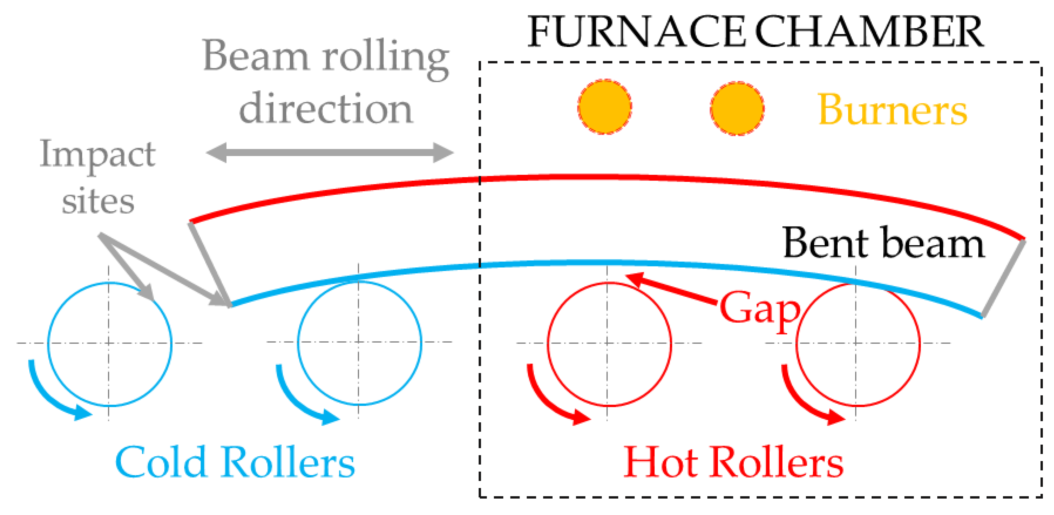
  • The thermal differences leading to beam bending were evened with radiation deflectors and a proper sitting of the beam on three or four rollers, depending on the stroke’s position, was achieved. Working loads were corrected this way, reducing the stress in the fillet radius.
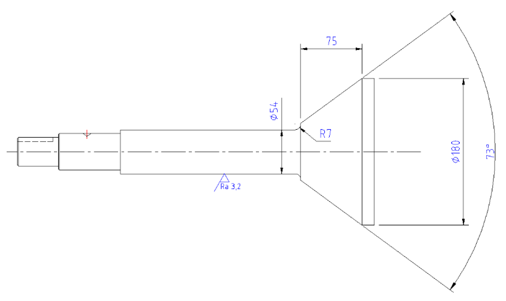
  • The design of the roll was made more robust by increasing the journal diameter from Ø54 mm to Ø64 mm and by reducing the stress concentration factor thanks to a fillet of R20 mm and tangent to the cone instead of a truncated R7 mm fillet (Figure 10).
These three actions led to an improved loading condition in which the following occurred:
-
The service loads were reduced by between 33% and 50% depending on the beam’s position (33% if the beam passed from sitting in two rollers to sitting on three rollers and 50% in the case in which the beams passed from sitting on four rollers to sitting on four rollers).
-
The generation of over temperatures in the fillet was avoided, so that the reduction of the hot strength was avoided.
-
The stress in the failure area was reduced by 40%. The main factor contributing to this improvement is an increased inertia when changing from Ø54 mm to Ø64 mm, as both the bending and torsion stresses in the failure area are inversely proportional to Ø3: 543/643 = 0.60.
This can be expressed in terms of principal stress (Equations (4)–(6)) to build the following new scenario:
σ b e n d i n g = 4 · M π · R 3 = 4 · 2600 · 0.21 π · 0.032 3 = 21   M P a ,
τ t o r s i o n = 2 · T π · R 3 = 2 · 170 π · 0.032 3 = 3   M P a ,
σ p r i n c i p a l   m a x = σ b e n d i n g 2 + ( σ b e n d i n g 2 ) 2 + τ t o r s i o n 2 = 21   M P a .
-
The stress concentration factor was reduced to 1.25 (r/d = 0.31 and D/d = 1.12 from the bending stepped round bar with a fillet chart in the work of [22]). Also introducing the scale (1.25) and roughness (1.1) leaves a peak stress of 1.25 × 1.25 × 1.1 × 21 = 39 MPa.
Adding up all the actions, the peak stress for the R = −1 fatigue condition in which the rollers work changed from 154 MPa in initial service to 39 MPa in the redesigned condition. The four-fold reduction of stress led to an improvement effect fatigue wise, as reflected in the fact that the modified rolls were in production for double the initial roll failure time without any trace of cracking after penetrant dye inspection. The new design was implemented in all the furnaces of the same family. This result emphasizes the importance of performing mechanical calculations that must consider all factors involved in service when designing new equipment.

4. Conclusions

The metallurgical study of the fractured rollers and the investigations on the actual operating conditions of the furnace allowed reaching the following conclusions:
-
The supply condition of the broken steel was correct and clearly different from its metallurgical condition on the fracture site.
-
The roller was designed against creep, but the failure was caused by mechanical fatigue crack growth combined with ductile collapse when the resistant section was severely reduced.
-
The actual metallurgical condition of the steel did not fit with the design working parameters that were expected.
-
The investigations performed on the running furnace confirmed that the working temperature on the failure site exceeded design temperature and that working loads even doubled design load at some positions of the stroke.
-
The actual working parameters perfectly fit the observations in the fractured component, both regarding microstructural and fractographical evolutions.
-
Actions against the root cause, leveling the contact of the rollers with the beam, adjusting the thermal barriers, and reducing the stress in the failure site were successfully implemented and the service times of the rollers working in these conditions doubled the failure times of the original broken rollers without showing any crack traces in liquid penetrant inspections.
This case study shows the importance of investigating the deviations between the expected working condition and the actual working condition when a failure analysis is performed. The operating temperature and loads are critical in furnace components. In terms of temperatures, it becomes critical to assess the carbide and sigma phase precipitation kinetics when dealing with embrittlement susceptible austenitic stainless steels. Regarding loads, not only the functional loads must be considered, but also thermal borne stresses, even those generated by faulty contacts caused by thermal expansion and bending. Design-wise, the recommendation of analyzing the loading scenarios due to deviations from expected service conditions for mechanical design reliability of new equipment is strongly underlined. When resistant section must be dimensioned for a rotary steel part that is susceptible to creep, it must be taken into account that the rotation compensates the creep and fatigue becomes a design factor that must also be considered.
The results and method followed in the above sections are of general application to production lines in cases of hot-stamping lines, and can be considered, along with conclusions of modelling given in the work of [26], as a key aspect of the high-production process currently in full use in automotive white-body assembly.

Author Contributions

The present work was conceptualized by B.G.-C., B.F., A.S., M.M., and G.A.; the failure analysis methodology was put in place by B.G.-C., B.F., M.M., and G.A.; hypothesis and result validation was performed by L.N.L.d.L.; working condition investigation was carried out by B.G.-C., B.F., and A.S.; writing—original draft preparation was performed by B.G.-C. and G.A.; writing—review and editing was carried out by L.N.L.d.L.; supervision was carried out by L.N.L.d.L.

Funding

This research was funded by the Basque Government, with budget from the Departamento de Industria, Innovación, Comercio y Turismo and from Fondo de Desarrollo Regional (FEDER) in the frame of the Etorgai Program supporting the LABEBERRI Project (exp. ER-2013/00032). Thanks are also due to funds from Excellence groups of the Basque university system n IT1337-19, and to projects Spanish Ministry of Science DPI2016-74845-R and RETOS NewMINE RTC-2017-6039.

Conflicts of Interest

The authors declare no conflict of interest.

References

  1. Karbasian, H.; Tekkaya, A.E. A review on hot stamping. J. Mater. Process. Technol. 2010, 210, 2103–2118. [Google Scholar] [CrossRef]
  2. Neugebauer, R.; Schieck, F.; Polster, S.; Mosel, A.; Rautenstrauch, A.; Schönherr, J.; Pierschel, N. Press hardening—An innovative and challenging technology. Arch. Civil. Mech. Eng. 2012, 12, 113–118. [Google Scholar] [CrossRef]
  3. Mori, K.; Bariani, P.F.; Behrens, B.-A.; Brosius, A.; Bruschi, S.; Maeno, T.; Merklein, M.; Yanagimoto, J. Hot stamping of ultra-high strength steel parts. CIRP Ann. Manuf. Technol. 2017, 66, 755–777. [Google Scholar] [CrossRef]
  4. Mori, K.; Maki, S.; Tanaka, Y. Warm and hot stamping of ultra high tensile strength steel sheets using resistance heating. CIRP Ann. Manuf. Technol. 2005, 54, 209–212. [Google Scholar] [CrossRef]
  5. Kolleck, R.; Veit, R.; Merklein, M.; Lechler, J.; Geiger, M. Investigation on induction heating for hot stamping of boron alloyed steels. CIRP Ann. Manuf. Technol. 2009, 58, 275–278. [Google Scholar] [CrossRef]
  6. Pedraza, J.P.; Landa-Mejía, R.; García-Rincón, O.; García, C.I. The effect of rapid heating and fast cooling on the transformation behavior and mechanical properties of an advanced high strength steel (AHSS). Metals 2019, 9, 545. [Google Scholar] [CrossRef]
  7. Rasera, J.N.; Daun, K.J.; Shi, C.J.; Souza, M.D. Direct contact heating for hot forming die quenching. Appl. Therm. Eng. 2016, 98, 1165–1173. [Google Scholar] [CrossRef]
  8. Oh, J.; Han, U.; Park, J.; Lee, H. Numerical investigation on energy performance of hot stamping furnace. Appl. Thermal. Eng. 2019, 147, 694–706. [Google Scholar] [CrossRef]
  9. Saez, A.; Angulo, D.; Berasategui, J. Advanced technology for hot stamping. Heat Process. 2018, 3, 77–80. [Google Scholar]
  10. Pantazopoulos, G.A. A short review on fracture mechanisms of mechanical components operated under industrial process conditions: Fractographic analysis and selected prevention strategies. Metals 2019, 9, 148. [Google Scholar] [CrossRef]
  11. Álvarez, J.A.; Lacalle, R.; Arroyo, B.; Cicero, S.; Gutiérrez-Solana, F. Failure analysis of high strength galvanized bolts used in steel towers. Metals 2019, 6, 163. [Google Scholar] [CrossRef]
  12. Zhang, W.; Wang, H.; Zhang, J.; Dai, W.; Huang, Y. Brittle fracture behaviors of large die holders used in hot die forging. Metals 2017, 7, 198. [Google Scholar] [CrossRef]
  13. Al-Meshari, A.; Al-Rabie, M.; Al-Dajane, M. Failure analysis of furnace tube. J. Fail. Anal. Preven. 2013, 13, 282–291. [Google Scholar] [CrossRef]
  14. Babakr, A.M.; Al-Ahmrai, A.; Al-Jumayiah, K.; Habiby, F. Failure investigation of a furnace tube support. J. Fail. Anal. Preven. 2009, 9, 16–22. [Google Scholar] [CrossRef]
  15. Acevedo, F.; Sáenz, L. Study of embrittlement in austenitic stainless steel AISI 304H with 15 years in service exposed to high temperature. Dyna 2018, 93, 428–434. [Google Scholar] [CrossRef]
  16. Yang, Y.P.; Mohr, W.C. Finite element creep-fatigue analysis of a welded furnace roll for identifying failure root cause. J. Mat. Eng. Perform. 2015, 24, 4388–4399. [Google Scholar] [CrossRef]
  17. Davies, J.R. ASM Specialty Handbook––Heat-Resistant Materials; ASM Materials, Materials Park: Russell, OH, USA, 1997. [Google Scholar]
  18. ASTM A479/A479M–18 Standard Specification for Stainless Steel Bars and Shapes for Use in Boilers and Other Pressure Vessels; ASTM International: West Conshohocken, PA, USA, 2013.
  19. ASTM E8/E8M–16 Standard Test Methods for Tension Testing of Metallic Materials; ASTM International: West Conshohocken, PA, USA, 2013.
  20. Pozo, D.; López de Lacalle, L.D.; López, J.M.; Hernández, A. Prediction of press/die deformation for an accurate manufacturing of drawing dies. Int. J. Adv. Manuf. Technol. 2008, 37, 649–656. [Google Scholar] [CrossRef]
  21. Gere, J.M. Mechanics of Materials; Brooks Cole: Hampshire, UK, 2003. [Google Scholar]
  22. Peterson, R.E. Stress Concentration Factors; John Wiley and Sons: New York, NY, USA, 1974. [Google Scholar]
  23. Shigley, J.E.; Mischke, C.R.; Brown, T.H., Jr. Standard Handbook of Machine Design; McGraw-Hill: New York, NY, USA, 2004. [Google Scholar]
  24. Milella, P.P. Fatigue and Corrosion in Metals; Springer Verlag: Milano, Italia, 2013. [Google Scholar]
  25. Nikitin, I.; Scholtes, B.; Maier, H.J.; Altenberg, I. High temperature fatigue behavior and residual stress stability of laser-shock peened and deep roller austenitic steel AISI 304. Scr. Mater. 2004, 50, 1345–1350. [Google Scholar] [CrossRef]
  26. Borja, F.; Beatriz, G.; Artola, G.; López de Lacalle, N.; Angulo, C. A Quick Cycle Time Sensitivity Analysis of Boron Steel Hot Stamping. Metals 2019, 9, 235. [Google Scholar] [CrossRef]
Figure 1. Picture of a cracked roller showing both aluminum build-up due to adhesion and aluminum infiltration across the full thickness of the roller wall.
Metals 09 00816 g001
Figure 2. General description of the failure site: (a) overview of the fracture location in the drive end of the roll; (b) detail of the fracture surface.
Metals 09 00816 g002
Figure 3. Most relevant dimensions of the original bell and journal design (dimensions in mm).
Metals 09 00816 g003
Figure 4. Sample of broken roll 1 (BR1) that was inspected.
Metals 09 00816 g004
Figure 5. Micrographs of the broken journals. Left. Carbide precipitation in grain boundaries and sigma phase nucleation in the fractured zone. Right. Regular solution annealed austenitic microstructure free of carbides and sigma phase in cold zone of the journal.
Metals 09 00816 g005
Figure 6. Fracture surface of broken roll 1 (BR1) (top) and BR2 (bottom). Left. Several fatigue nucleation sites marked by arrows and crack stop lines marked with discontinuous lines. Right. Final ductile collapse surface of the roll.
Metals 09 00816 g006
Figure 7. Scanning electron microscopy (SEM) micrographs of the three main fractographic features observed in BR1 and BR2. Top left. Fatigue nucleation site with the crack growth direction marked by arrows. Top right. Fatigue lines on the oxidized surface of the fatigue cracked area. Bottom. Ductile dimples in the final collapse zone.
Metals 09 00816 g007
Figure 8. Scheme of the effect of temperature differences between the top and the bottom of the beam. The rollers marked as “hot rollers” correspond to the fractured ones.
Metals 09 00816 g008
Figure 9. Loading scheme of the roller when the beams are sitting on four rollers at the same time (dimensions in mm).
Metals 09 00816 g009
Figure 10. Final journal design that substituted the original geometry (dimensions in mm).
Metals 09 00816 g010
Table 1. Specification and actual measured chemical composition of the rollers in % weight (expanded uncertainty K = 2 of the measurements <0.03%).
ReferenceCMnSiSPCrNi
AISI 304 Specification [18]0.08<2<1<0.03<0.04518–208–10.5
Broken Roll 1 (BR1)0.051.040.62<0.02<0.0219.589.14
Broken Roll 2 (BR2)0.061.050.58<0.02<0.0219.619.15
Table 2. Purchasing specification and actual tensile properties for the BR1 and BR2 samples (indicated tolerance corresponds to expanded measurement uncertainty K = 2).
ReferenceYield Strength
Rp0.2 (MPa)
Tensile Strength
Rm (MPa)
Elongation
E (%)
Reduction in Area
RA (%)
Purchasing specification from design>210>560>58-
Tensile specimen from BR1248 ± 5602 ± 561.0 ± 1.575.0 ± 1.5
Tensile specimen from BR2250 ± 5610 ± 560.0 ± 1.574.0 ± 1.5

