Article

Modeling the Effect of Different Support Structures in Electron Beam Melting of Titanium Alloy Using Finite Element Models

by
Usama Umer
1,*,
Wadea Ameen
1,2,*,
Mustufa Haider Abidi
1,
Khaja Moiduddin
1,
Hisham Alkhalefah
1,2,
Mohammed Alkahtani
1,2 and
Abdulrahman Al-Ahmari
1,2
1
King Saud University, Advanced Manufacturing Institute, Riyadh 11421, Saudi Arabia
2
Industrial Engineering Department, College of Engineering, King Saud University, Riyadh 11421, Saudi Arabia
*
Authors to whom correspondence should be addressed.
Metals 2019, 9(7), 806; https://doi.org/10.3390/met9070806
Submission received: 3 July 2019 / Revised: 14 July 2019 / Accepted: 19 July 2019 / Published: 22 July 2019
(This article belongs to the Special Issue Modeling Metal 3D Printing Processes)

Abstract

:
Electron beam melting (EBM) technology is a novel additive manufacturing (AM) technique, which uses computer controlled electron beams to create fully dense three-dimensional objects from metal powder. It gives the ability to produce any complex parts directly from a computer aided design (CAD) model without tools and dies, and with variety of materials. However, it is reported that EBM has limitations in building overhang structures, due to the poor thermal conductivity for the sintered powder particles under overhang surfaces. In the current study, 2D thermo-mechanical finite element models (FEM) are developed to predict the stresses and deformation associated with fabrication of overhang structures by EBM for Ti-6Al-4V alloy. Different support structure geometries are modeled and evaluated. Finally, the numerical results are validated by experimental work.

Graphical Abstract

1. Introduction and Literature Review

Additive manufacturing (AM) is one of the latest approaches used for manufacturing products in advanced applications. In AM, parts are fabricated by adding material as layers. This is the opposite of the machining process, in which the material is removed or subtracted from a block to achieve the shape of the desired object. Electron beam melting (EBM) is relatively new AM technology; it works under the powder bed fusion process. It was developed in 1997 by Arcam AB Company (Sweden). EBM is used to produce parts for high performance applications within the biomedical, aerospace, and automotive industries. This technology is more effective with complex parts manufactured in low volumes where machining and casting would require too much lead-time and wastage of material. However, AM has some limitations too. The major problem is the distortion and warping associated with the building of overhang structures. In EBM, the overhang surfaces are in contact with loose powder, which is not sufficient to support the molten metal. In addition, the powder bed is not efficient enough to take away the heat from the overhang surfaces because of poor thermal conductivity. This leads to dross formation, distortions, and warping [1].
Vayre et al. [2] investigated some key manufacturing constraints while designing parts for EBM. They studied the removal of unmelted powder and the needs for support structures for different design configurations. The authors estimated powder depths that can be removed easily for a set of geometric features using available powder recovery system. The authors also concluded that for the developed test parts, support structures were only needed when they oriented approximately 90° to the building axis.
A similar study was done by Drescher et al. [3] to find out the relationship between depth of powder removed and pore size for net-structured titanium parts using EBM. They performed powder removal for several net-structured parts using the established powder blast system. They reported that a linear relationship exists between the depth of powder removed and pore dimensions. To minimize the porosity in the Ti-6Al-4V parts produced through selective laser melting (SLM), a combination of optimized parameters and intensified intrinsic heat treatment was applied [4]. It incites extensive martensite decomposition α’ to α + β along the building direction. This results in the creation of a uniform, fine lamellar α + β microstructure. For the regions that were highly affected by the intensified intrinsic heat treatment, a 3D interconnected network of β was created.
Since a complex thermal processes is undergone by materials during metal AM, brittle martensitic microstructures unsuitable for structural applications are usually obtained. Therefore, post thermomechanical procedures are generally applied to these parts, however each process has its own pros and cons. Barriobero-Vila et al. [5] aimed at altering Ti alloys to the metallurgical conditions of AM by exploring metastability around peritectic and peritectoid reactions. Adding peritectic forming elements showed positive results in terms of microstructure stability.
Vora et al. [6] utilized blended powders to develop residual stress free overhang parts in SLM and EBM. Al-Si and Ti64-Cu alloy systems were used in SLM and EBM respectively. T-shaped parts were designed with 2 mm thick surfaces with an overhang length of 5 mm. They were able to produce SLM parts without any warping and achieved 88% reduction in warping compared to the benchmarking EBM Ti-6Al-4V part. Tounsi and Vignat [7] proposed a methodology for designing and optimizing support structures in the electron beam melting process. New support structures were used and their efficiency was studied. The results showed an enhancement for reducing geometric defects.
Ali et al. [8] suggested real time dynamic change in the build parameters to reduce residual stresses in the selective laser melted Ti-6Al-4Vparts. They found that a temporary change in the layer thickness during the build redistributed the stresses and overall residual stresses were reduced by 8.5%. A support structure design methodology was developed by Kuo et al. [9] to minimize the deformation using the least amount of support material in additive manufacturing processes. They proposed a repulsion index which allowed easy removal of support structures and a weighting function which estimated the cost by considering the time required to build the supports. A multi-objective topology optimization method was adopted that included the proposed repulsion index and cost formulation. Manufacturability of overhanging holes during EBM build of Ti-6Al-4V parts was analyzed by Wadea et al. [10]. The parts were assessed based on geometrical accuracy, mechanical properties, and microstructures. They concluded that overhanging holes up to a certain size could be built successfully without the need for any support structures. Beyond the threshold value, suitable support structures are needed and can be selected via trade-off between manufacturing time, cost, and accuracy.
Weißmann et al. [11] developed single Ti-6Al-4V struts using SLM and EBM with different part orientations. They showed that a functional correlation exists between the compressive strength and slenderness ratio in addition to the equivalent diameter and height of the EBM and SLM fabricated parts. In another study [12], cuboids were added to the conventional block support in overhanging structures made by SLM. They utilized Taguchi method to see the effects of geometric design modifications of support structures on surface roughness and deformation. It was found that these cuboids can reduce the deformation, but their effects were less in comparison to the teeth structures. Oter et al. [13] checked different support profiles for dimensional stability and surface quality in direct metal laser sintering of maraging steel. They reported that overhang structures with weak supports profile had low surface roughness and required less post processing at the expense of surface quality. The effect of laser power on non-horizontal 316L stainless steel overhanging structures using SLM was studied by Shi et al. [14]. They found that smaller laser power remelting should be utilized for better forming and surface quality.
Zäh and Lutzmann [15] developed a thermo-physical finite element (FE) model using a single scan vector to determine the effects of scan speed and beam power on melt pool geometries while developing stainless steel 316L parts by EBM. Higher length-to-width ratios of melt pool resulted in several melt balls instead of solidifying as a smooth layer as reported in [16]. Using a parametric simulation study, they concluded that a combination of beam scanning speed of 50 mm/s and beam power of 150 W resulted in a minimum length-to-width ratio of approximately 1.3.
Shen and Chou [17] developed two thermo-mechanical FE models, one with single straight scan path and the other with multi-layer cross scan path, in order to investigate the effects of different scan patterns on residual stresses and deformation of Ti-6Al-4V parts produced by EBM. However, they validated simulation results with electron beam welding of Inconel-706 due to lack of experimental published results for EBM at that time. In another study [18] by the same authors, these FE models were employed to find out the critical substrate thickness above which the preheating temperature penetration would not be effected. The preheating temperature penetration was found out to be 0.5 mm with the critical substrate thickness of 10 mm. The reported results, however, were without any experimental validation.
Cheng et al. [19] developed thermo-mechanical FE models to simulate warping associated with a simple overhang structure. They concluded that slow heat dissipation around the overhang area due to poor thermal conductivity of the powder resulted in higher temperatures that lead to warping and distortions. It was also reported that lower powder porosity might reduce residual stresses associated with overhang warping. No experiments were performed to validate the simulation results.
Cheng and Chou [20] developed 2D FE models to simulate EBM of Ti-6Al-4V structures to evaluate the effects of process parameters, overhang and support configurations, and powder porosity. They reported less deformation with an increase in beam scanning speed and spot diameter. It was found that smaller tilt angles of overhang structures resulted in large deformations. In addition, powder with a low porosity level was recommended to suppress the overhang deformations. Later, a new method based on combined heat support and anchor design was proposed by Cheng and Chou [21] to reduce the warping associated with overhang structures by developing 3D FE models. They reported significant reduction in warping using the proposed methodology.
Han et al. [22] developed overhanging structures for AlSi10Mg alloy using the laser powder bed fusion process. They concluded that the utilization of support structures improved the manufacturability and structural integrity of the overhanging structures. They developed half and full circle overhanging structures and reported that the influence of support was found to be more beneficial for circularity of overhanging holes. Cheng et al. [23] utilized topology optimization to design support structures in laser powder bed metal additive manufacturing. Instead of performing temperature displacement analysis, an inherent strain method was adopted to reduce computational time for predicting residual stresses. The optimization problem was formulated to minimize the mass of sacrificial support structures under stress constraint. They showed that optimized structures achieved a weight reduction of around 60%. Lu et al. [24] developed a 3D thermo-mechanical model in laser solid forming of Ti-6Al-4V parts. They simulated 40 layers of metal deposition using different scanning strategies. By performing the sensitivity analysis, they showed that the thermal expansion coefficient and the elastic stiffness of the material had significant effects on mechanical behavior of the build parts.
It is evident from the literature review that model validation using in-house experimental results is lacking in most simulation studies. In this work, 2D finite element models have been developed assuming plane strain formulations to model the effects of different support structures in EBM. The deformation associated with these models are compared with the in-house fabricated EBM parts. In addition, residual stresses and temperatures associated with these models are also analyzed and discussed.

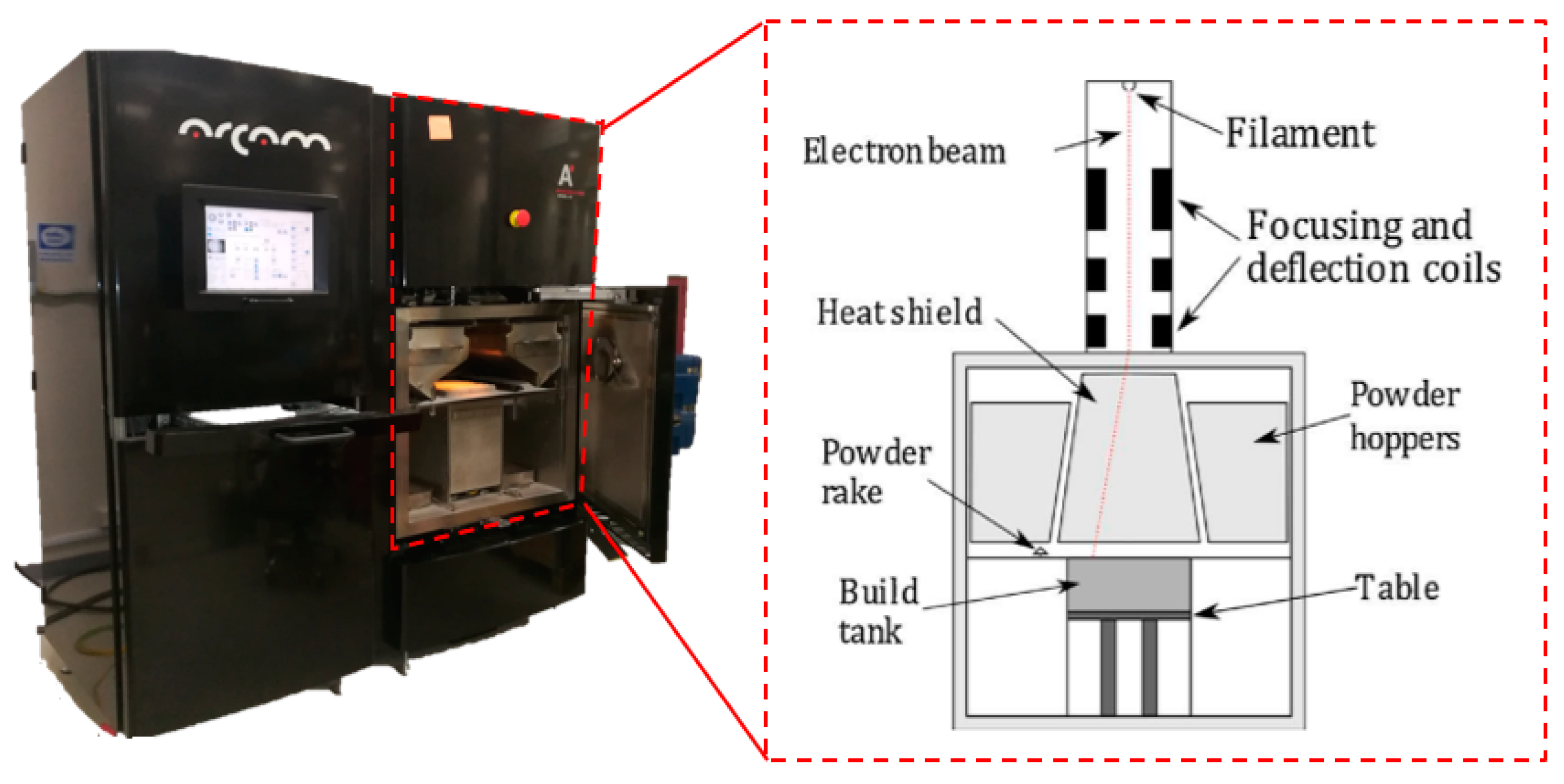
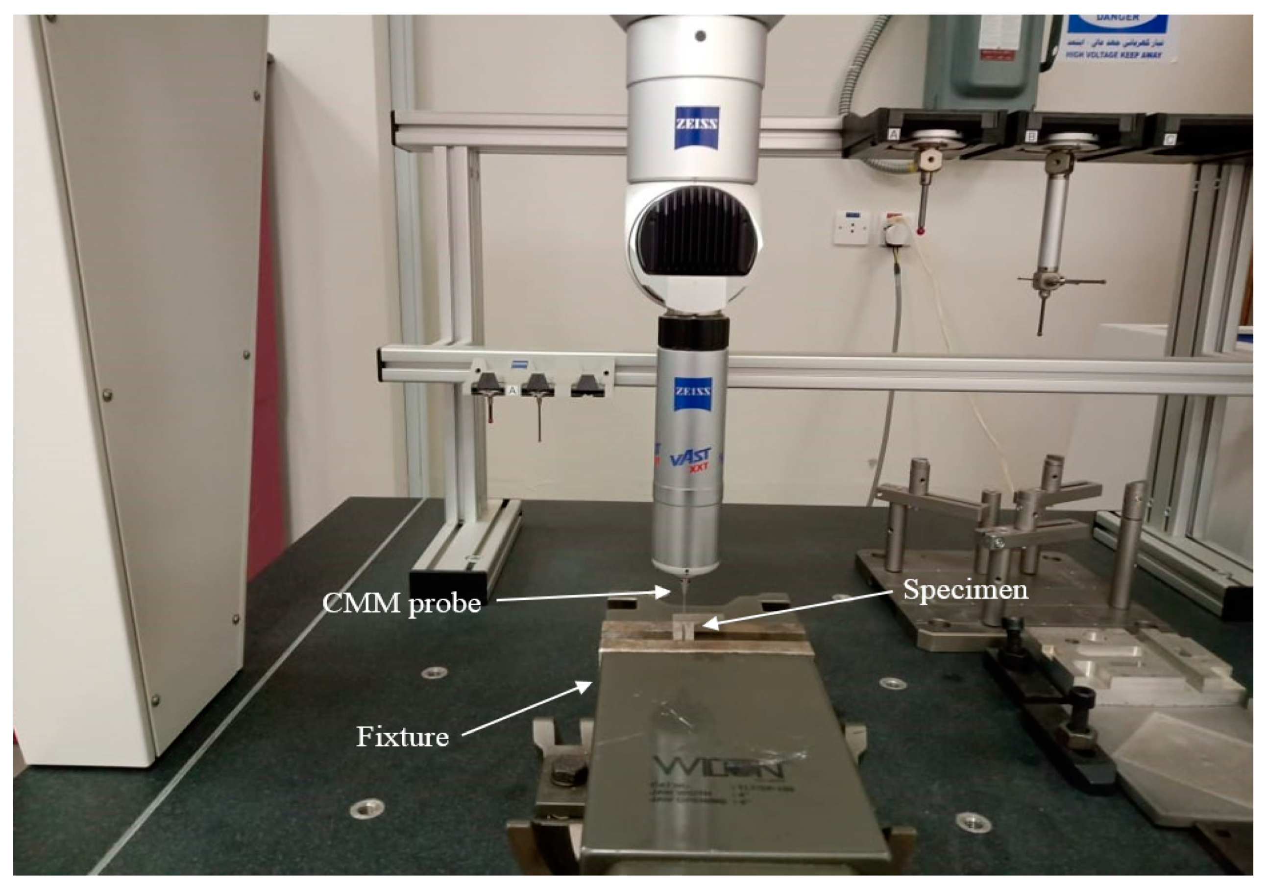
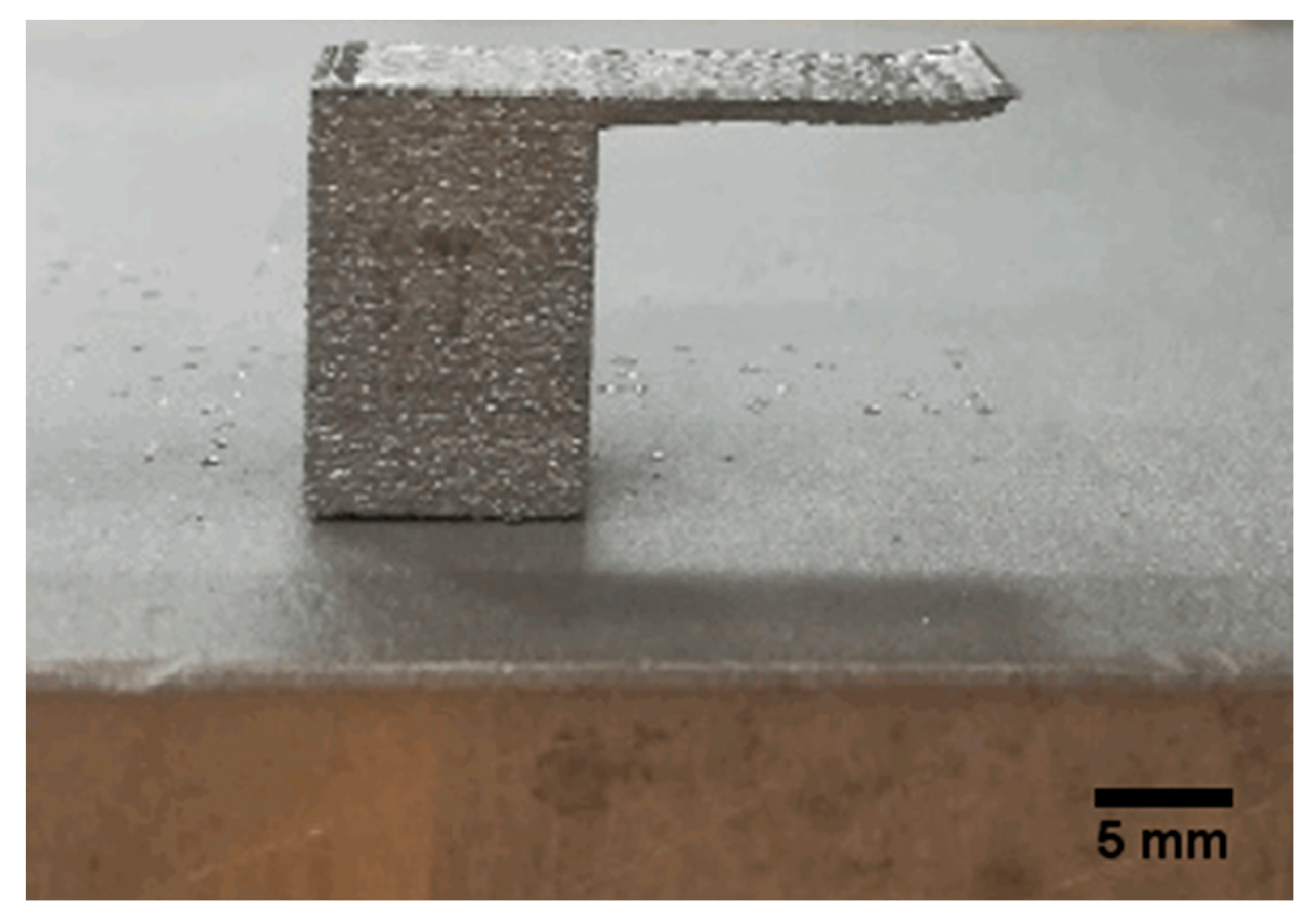
2. Experimental Setup

In order to investigate the effects of different support structures on overhang warping, five models (model A to model E) were designed and build using the electron beam melting (EBM) process as shown in Figure 1. Model A was a reference part without any support structure, whereas model B and C were designed with straight column support as shown in Figure 1. Models D and E were designed using Y-shaped supports with a different middle column as illustrated in Figure 1. For all models the thickness of the support columns was 0.6 mm, which is the minimum wall thickness that can be produced using the available EBM technology [25]. The computer-aided design (CAD) models were converted to stereolithography (STL) format and imported to Magics software for adjusting the orientation and fixing the STL model’s errors. Titanium powder alloy (Ti-6Al-4V) with particle sizes ranging between 53–107 µm with a mean of around 75 µm was used in the current study as shown in Figure 2.
ARCAM (Sweden) EBM A2 technology was utilized for fabricating the specimens with default preheat and melting parameters set as shown in Figure 3. The electrons were emitted from a filament, which was heated at above 2500 °C. These high-energy electrons were accelerated through the anode.
The magnetic field of the lenses brought the beam into focus and the scanning was carried out electromagnetically. When the high-energy electrons hit the titanium powder, the kinetic energy was transformed into heat. The titanium powder was fed by gravity from cassettes and raked into layers across the table. The built specimen was lowered on the built table with each layer melt cycle. The heat melted the metal powder and the powder was controlled by altering the current of the beam. All the process was performed under vacuum, which eliminates impurities and yields high strength properties of the material. The material can incorporate a controlled porosity lattice structure and scaffold which helps in bone growth and reduces the number of process steps. The machine was kept in high vacuum and the electron beam melted the titanium metal powder consecutively layer upon layer. Each layer was 0.05 mm in thickness. Once the build was finished, the parts were left for some hours for cooling. Table 1 presents the parameters used in current study.
The fabricated specimens were cleaned from the un-melted powder by sandblasting. The specimens were detached from the base plate by applying a very low force at the parting line using a sharp tool. In order to evaluate the overhang deformation, the coordinate measuring machine (CMM) was employed as shown in Figure 4. The lower left corner of the solid support was used as a reference point for measuring the coordinates of overhang warping. The total deformation at the extreme point of the overhang area was calculated using the difference between coordinates of the build part and the CAD model. The reference and measuring points are marked as ‘O’ and ‘P’ in Figure 1. Each measurement was performed three times using a highly accurate touch-trigger probe mounted on the CMM and the average value was calculated.

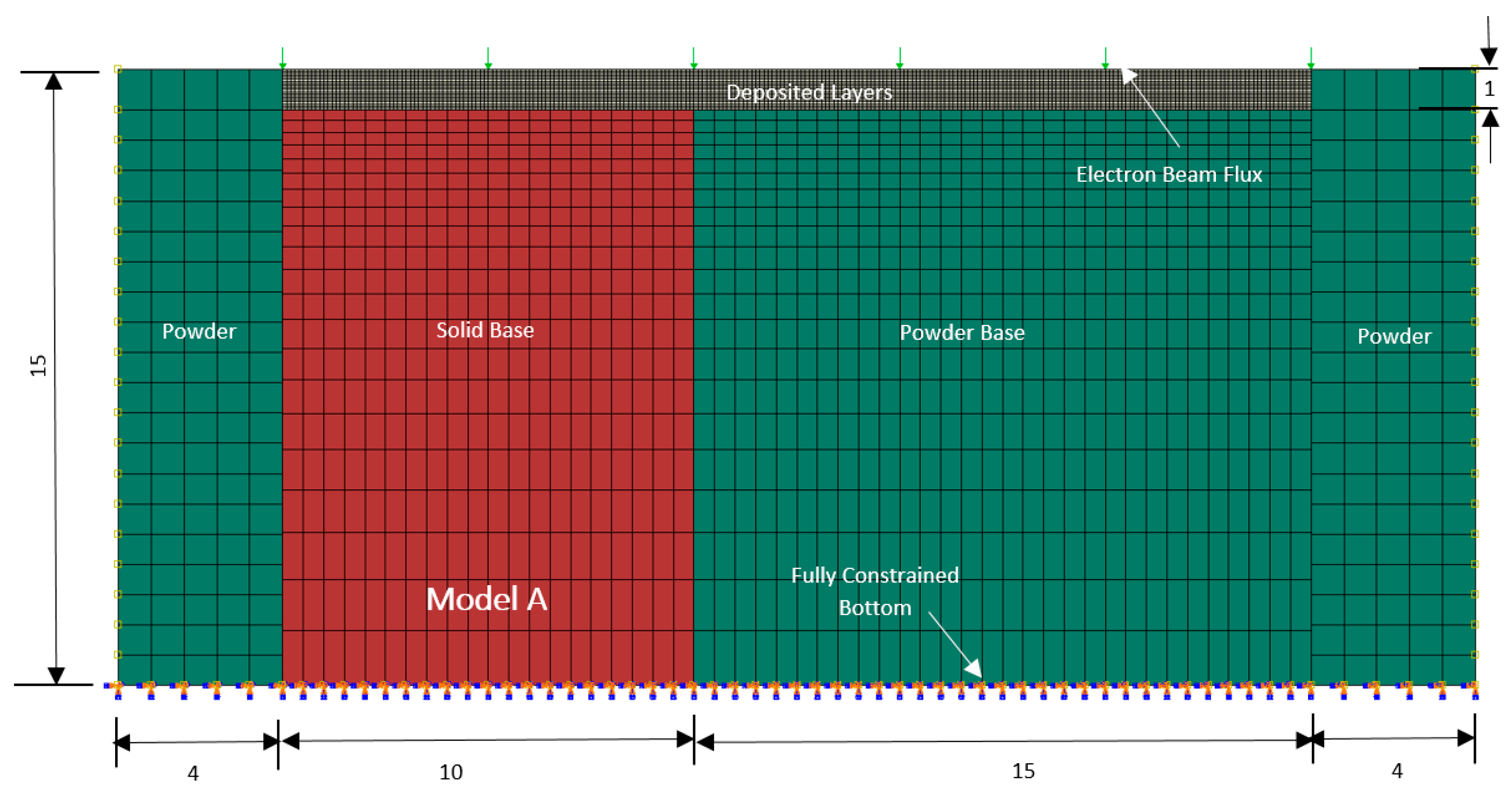
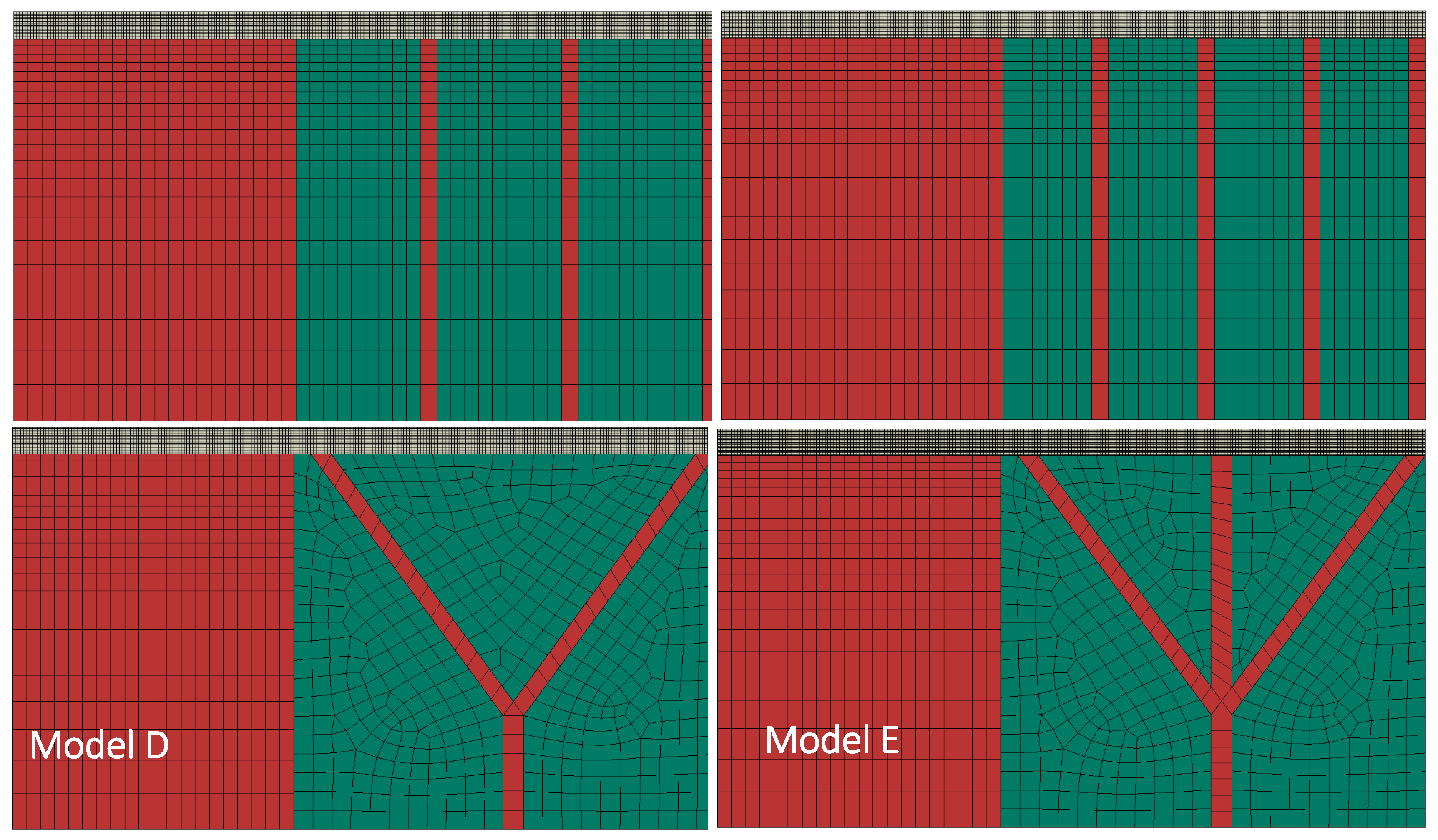
3. Finite Element Models

The temperature distribution during the EBM process can be obtained from the general equation of heat conduction with the moving heat flux and it is given by [16]:
2 T + g ˙ k = 1 α ( T t + v s T x )
where T represents the temperature, g ˙ is the rate of heat absorption, k is the thermal conductivity, α is the thermal diffusivity, and v s is the speed of the moving heat flux in the x-direction. The phase transformation has been modeled considering the volumetric fraction of liquid ( v f ) and latent heat of fusion ( L f ) . Thus, the enthalpy h ( T ) of the material at any temperature T is defined as:
h ( T ) = c d T + L f v f
where c is the specific heat and v f is dependent on solidus ( T S ) and liquidus ( T L ) temperatures and given by:
v f = 0 T < T s , T T S T L T S   T s T T l , 1 T > T l
Heat distribution due to the movement of the electron beam is modeled using a volumetric heat source having Gaussian distribution along the material surface and it is given by [20]:
g ˙ = η × H s × I y D
where
I y =   1 0.75   { 2.25   ( y s ) 2 + 1.5 y s + 0.75 }
H s = 2 V I π d 2 exp   {   2 ( x x s ) 2 d 2 }
where η is absorption coefficient, D is the penetration depth, V is the applied voltage, I is the beam current, and d is the beam spot diameter.
Temperature dependent mechanical and thermal properties of Ti-6Al-4V were utilized in FE models. They were collected from various sources [26,27,28] and are shown in Table 2. The thermal conductivities of solid Ti-6Al-4V alloy and sintered powder with 50% porosity are very much different [29]. For example at 25 °C, the thermal conductivity of solid alloy is ten times higher than the thermal conductivity of sintered powder.
Coupled temperature displacement analysis were performed with 2D models using ABAQUS/Standard to simulate deformation and warping associated with models built using the EBM process. The simulation study considered the deposition of 20 layers each having a thickness of 0.05 mm totaling 1 mm thickness for the overhang layer. The same dimensions were used both for the experiment and for simulation. The finite element mesh with the boundary conditions for model A described earlier is shown in Figure 5.
The model initial temperature was set to the preheat temperature of the powder. The temperature boundary condition for the bottom layer of solid and powder base was also set to the preheat temperature of the powder. The transformation of a single powder layer into solid layer was accomplished in two steps. First, there was a heating step corresponding to electron beam movement on the layer in x-direction. The electron beam source was modeled using the DFLUX subroutine, which is based on the mathematical model described earlier. The phase transformation of the powder layer into liquid and then solid was modeled using the UMATHT subroutine and the thermal properties of the phase were changed accordingly. In the second step the layer was allowed to cool to the preheat temperature and since the fabrication took place in a vacuum, any convection heat transfer was ignored and the cooling was supposed to take place by radiation mode only. The Stefan Boltzmann constant was used for radiation heat transfer with consideration of emissivity of the material, i.e., 0.7 [25]. All the layers above the target layer were deactivated using *MODEL CHANGE command available in ABAQUS/STANDARD and the corresponding elements were removed from the particular steps.
In this way, the model contains 40 steps for the deposition of 20 layers. The last step allowed the model to cool to room temperature and took approximately 17 min. Continuum plane strain elements with temperature degree of freedom (CPE4T) were used in coupled temperature displacement analysis. A very fine mesh was used for the deposited layers to account for steep temperature gradients across the deposited layers. A variable size mesh was used for the solid and powder substrate and it got finer close to the deposited layers as shown in Figure 5. In the same fashion, FE mesh for models with support structures, i.e., models B to E, were developed as shown in Figure 6. Contact between the layers and the powder-base was modeled using SURFACE-TO-SURAFACE CONTACT available in ABAQUS/STANDARD. On the other hand, the layers were attached to the solid-supports using mesh based TIE-CONSTRAINT. The models were run on a Dell Precision T1650 Workstation and required approximately 29 h of computational time for the deposition of 20 layers.

4. Results and Discussions

The fabricated model without support structure (model A) using EBM is shown in Figure 7. The warping effect at the extreme point on the overhang edge can be clearly observed in the fabricated model. Figure 8 shows models fabricated with support structures. As depicted, the warping effect was very much suppressed due to support columns and these models have comparable deformations.
Figure 9 shows a comparison for maximum total deformations obtained using experiments and simulations for all models. For all models, simulation results underestimated the deformations and the errors were around 22% approximately. The difference was mainly due to the assumption of simplified plane strain formulation (2D models), i.e., no deformation was assumed in the lateral direction. The errors could also be due to deviation in material properties and neglecting deformations in the base part prior to the deposition of top layers. However, it can be realized that these models are able to capture the correct trend with respect to the deformation change due to different support structures as shown in Figure 9.
Total deformations obtained after the final cooling step are shown in Figure 10. As expected, deformations associated with model A were high and warping was clearly shown along the overhang area, i.e., the surface profile obtained using simulation was very much similar to the EBM fabricated part as shown in Figure 8. Models B to E showed low and comparable deformations due to their support structures. Model C with four straight column supports showed the least deformation whereas model D with Y-shaped supports had high deformation among other support structures. However, the differences were minor, i.e., around 3–4% and the choice of support structure depended on tradeoff between material utilization and structural rigidity.
In the EBM process, the building time involves the time for the spreading of powder on the build platform, preheating time, powder-melting time, and the time for lowering the build platform by one layer of thickness. Melting time is very short in comparison to the total cycle time. Adding the support structures within the part height slightly increased the build time. In the current study, the models with support structures took around 3.20 to 3.23 h, whereas the model without any support structure took 3.1 h to build.
As EBM is a thermal process, stresses and deformations associated with the build part are largely dependent on temperature gradient between the layers. Each layer is formed with a heating step with an electron beam followed by a cooling step on account of radiation. In other words, each layer undergoes both expansion and contraction and these effects are further amplified by slow heat transfer due to poor thermal conductivity of the powder material. Thus, analysis of the temperature profile during the buildup of layers is crucial in order to minimize distortion and warping associated with the overhang structures.
Figure 11 shows the temperatures generated during electron beam scanning of the third layer for model A and model B. It was found that higher temperatures were generated at the overhang area during the formation of initial layers. As the part build proceeds, temperature reduced a bit and became steady. This can be accounted for by the thermal conductivity difference between the powder and solid titanium alloy.
It was evident that temperatures were lower in model B in contrast to model A. This is again emphasizing increased heat transfer due to higher thermal conductivity of solid supports and consequently higher deformation/warping was expected with model A upon final cooling. Similar findings are reported by other researchers during EBM build of Ti-6Al-4V parts [15,16,17]. After electron beam scanning, each layer was allowed to cool to preheat temperature by radiation and there existed a low temperature gradient after the end of cooling step as shown in Figure 12. Considering the solidus and liquidus temperatures of the alloy and the current temperature distributions, the phase transformation from powder to liquid and liquid to solid alloy could be predicted. Similarly, the temperature contours were also helpful in determining the size and shape of the melt pool during each layer build-up. As discussed earlier, a higher aspect ratio for the melt pool results non-uniform solidification and results in melt balls instead of solid layers [14]. Consequently, these temperature predictions would be helpful in predicting these defects and EBM parameters could be optimized accordingly.
The residual stresses in the electron beam scanning direction after the final cooling step are shown in Figure 13. It is clear from the figure that the residual stresses pattern for the model without support was very much different from the models with support structures. For model A around the overhang area, the outer layers were under tensile residual stresses while the inner layers were under compressive residual stresses. This distribution is typical and associated with warping/distortion areas. In contrast, the residual stress pattern was tensile and fairly uniform for the layers over the solid support area and compressive residual stresses were visualized around the solid support-layers interface area.
Residual stress contours for models B to E were very much similar. Uniform tensile residual stresses were seen for the layer overhang areas. These were balanced by the compressive residual stresses inside the solid supports as shown in Figure 9. Higher tensile and residual stresses were found with models B and C in comparison to models D and E as they were providing stronger support due to straight columns connected to the base plate. The residual stress patterns for the EBM build parts were very much similar to the work reported in [19,30]. The difference in the residual stresses pattern for the supported and unsupported models is illustrated by plotting some of the values for the deposited layers for model A and B as shown in Figure 14.
The following are the limitations of this study:
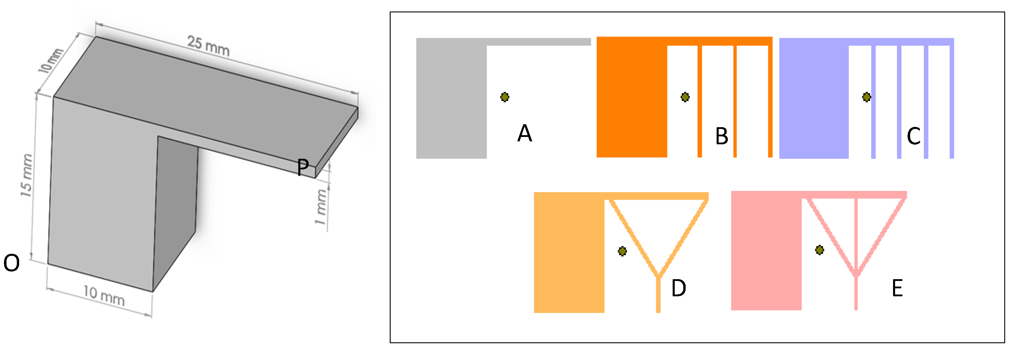
  • Plane strain formulation was considered, i.e., lateral distortions can’t be predicted.
  • Due to unavailability of data, mechanical properties of solid and powder alloys were considered the same.
  • Simulation of a complete part was not considered due to the requirement of huge computational time. So, deformations present in the base part prior to the deposition of the top 20 layers was ignored.

5. Conclusions

In the current study, 2D FE models with plane strain formulations showed promising results to predict the effects of different overhang structures on deformation and warping associated with the EBM build of Ti-6Al-4V parts. As the coupled temperature displacements analysis are computationally expensive, the models were developed to simulate the building of the top 20 layers only with 2D plane strain elements having temperature degrees of freedom. Analysis of experimental results showed that deformation and warping associated with the EBM parts were influenced by the choice of support structure. From FE analysis, it was concluded that the 2D plane strain models are capable of predicting these variations and the results and in agreement with the experimental work. In addition, the temperature contours during the part building gave insights regarding phase transformation and melt pool geometry which in turn were helpful in predictions of metallurgical defects. The residual stresses inside the built part were also predicted after allowing the model to cool down to room temperature. In summary, the following conclusions can be drawn from this work:
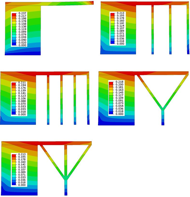
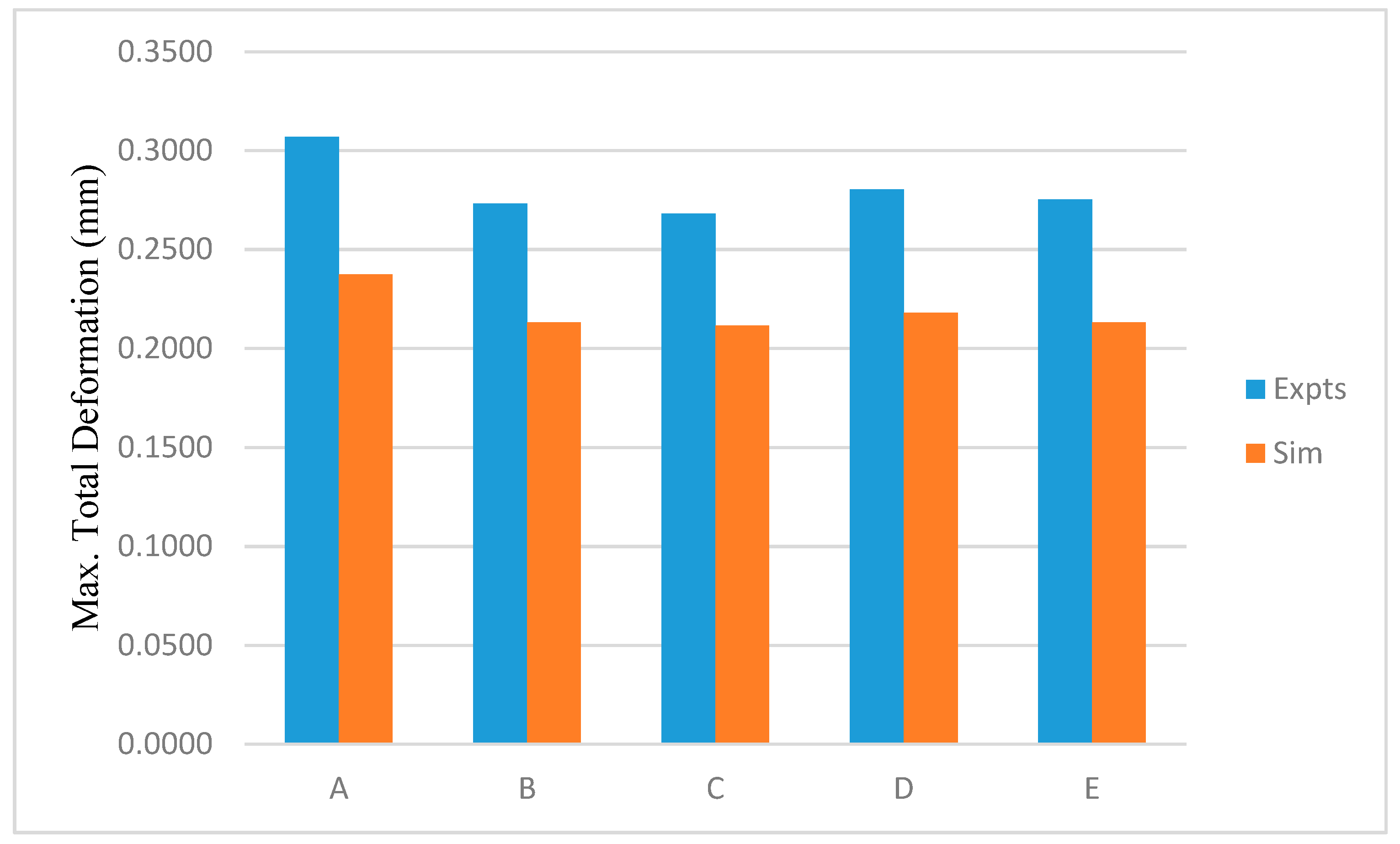
  • From the above analysis, it can be concluded that 2D FE models based on plane strain formulations are useful in predicting the overhang deformations for EBM built parts.
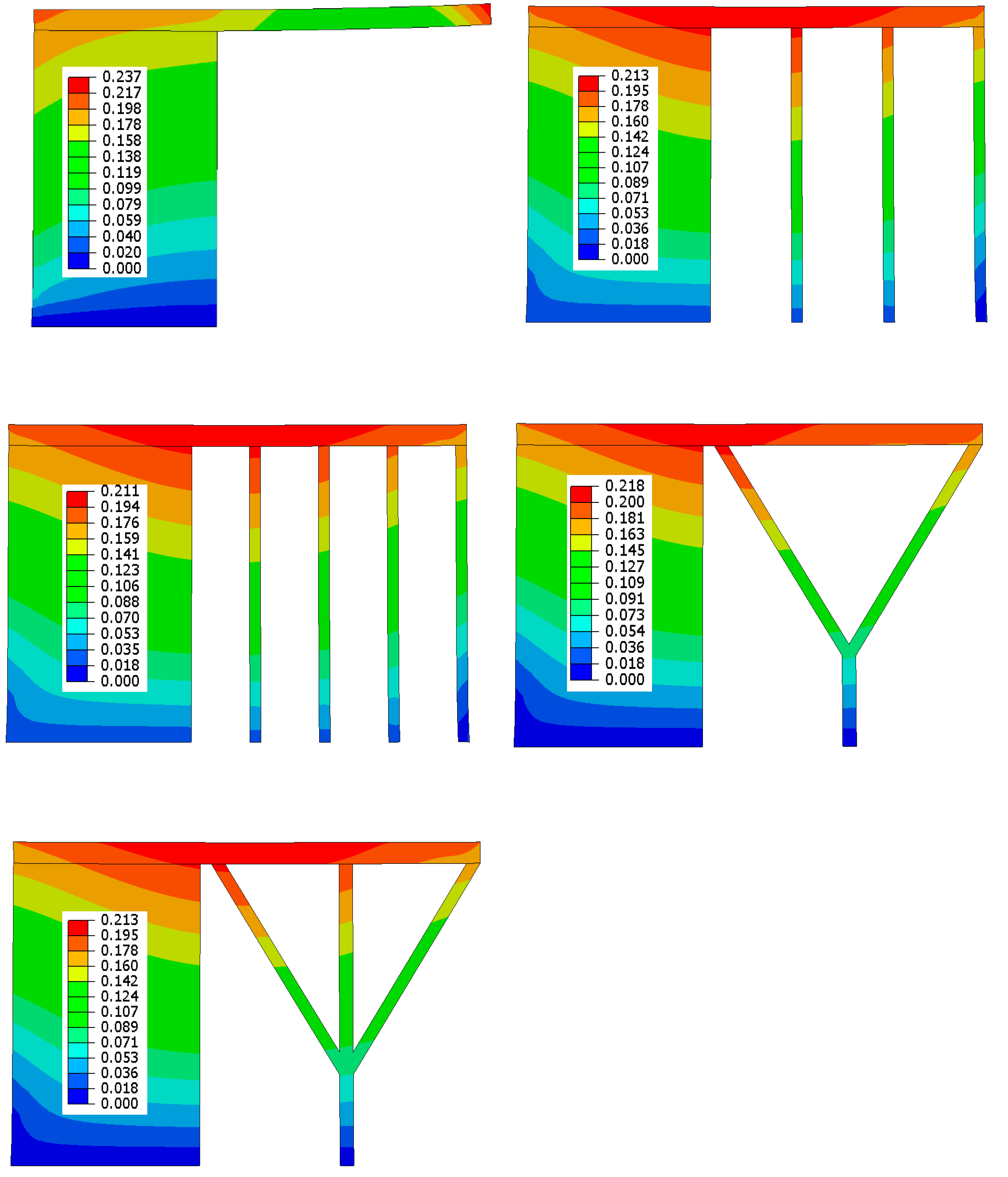
  • The FE models underestimate the deformations in all cases and the errors are around 22%. However, the models are able to predict the effects of different support structures on overhang warping up to a reasonable degree of accuracy.
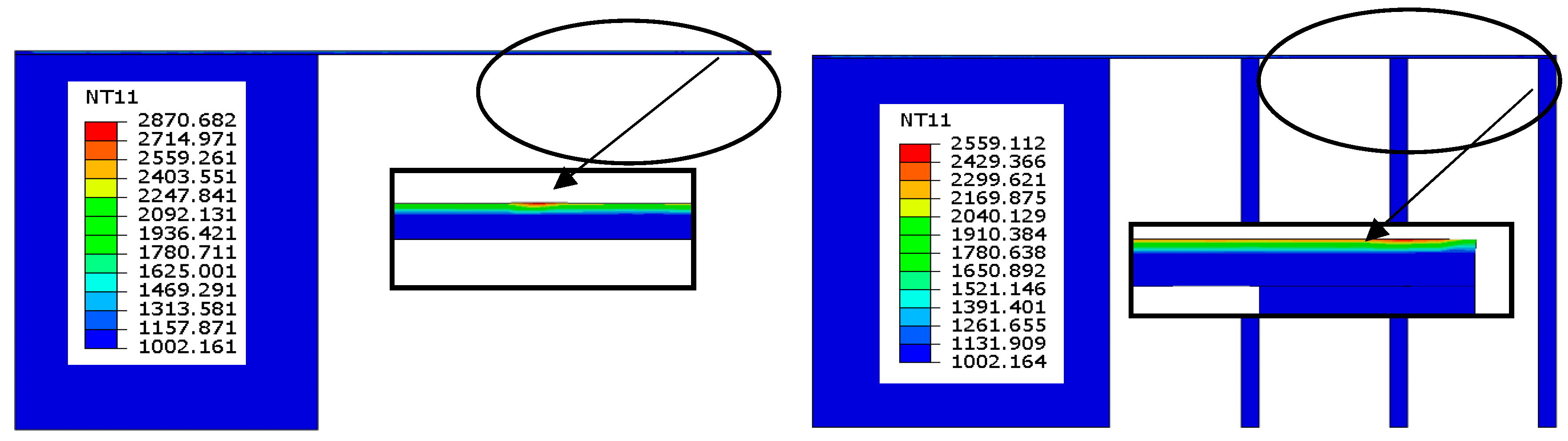
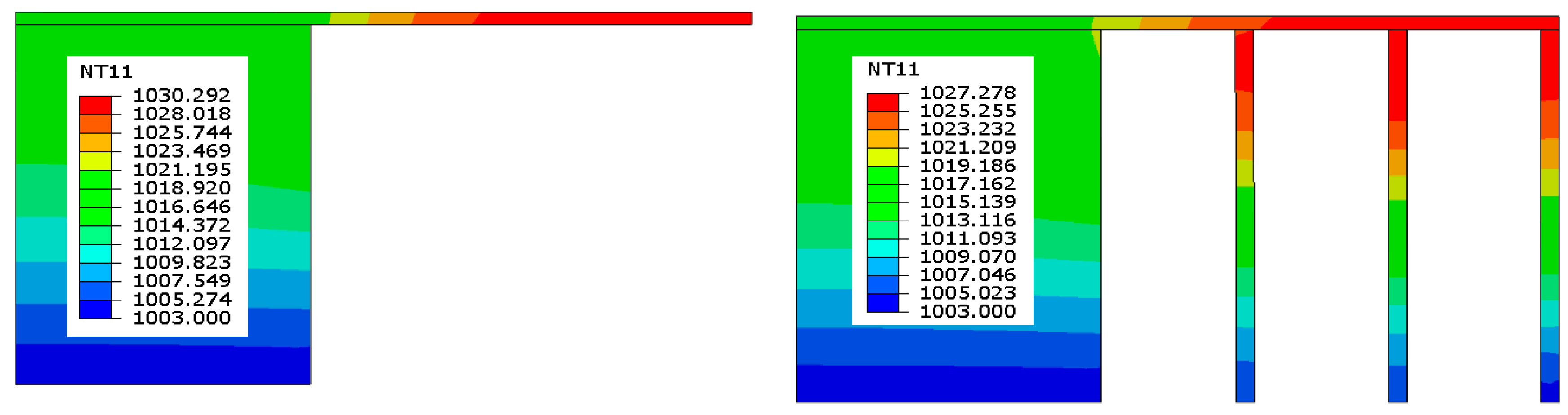
  • The temperature predictions during each layer build-up could be useful in determining the phase transformation from powder to liquid and liquid to solid alloy.
  • These FE models are also useful in determining the size and duration of the melt pool during each layer build-up.
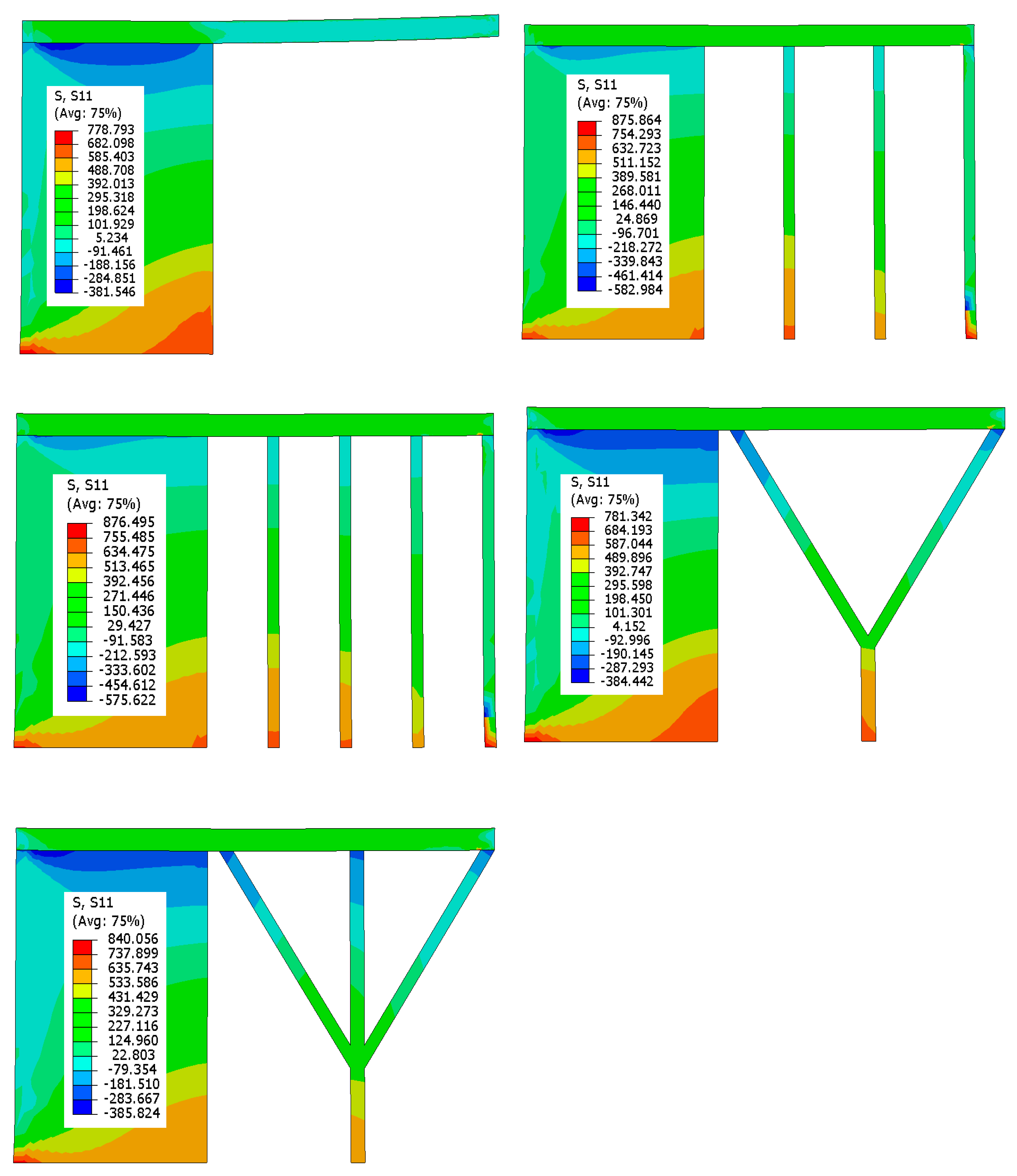
  • Residual stress patterns for the deposited layers are found to be very much different from the un-supported model and the overhang areas show fluctuating stresses from tensile to compressive.
  • The deposited layers for the models with support structures show uniform tensile stresses, which are balanced by the compressive stresses inside the support columns.

Author Contributions

Conceptualization, U.U., and W.A.; methodology, U.U., M.H.A., and W.A; software, U.U.; resources, W.A. and A.A.-A.; validation, K.M., M.H.A., and H.A.; formal analysis, M.A.; investigation, W.A., A.A.-A.; resources, W.A.; data curation, K.M.; writing—original draft preparation, U.U.; writing—review and editing, M.H.A.; visualization, M.H.A.; supervision, A.A.-A., H.A., and M.A.; project administration, H.A.; funding acquisition, M.H.A.

Funding

This research was funded by Deanship of Scientific Research at King Saud University, grant number RG-1440-026.

Acknowledgments

The authors extend their appreciation to the Deanship of Scientific Research at King Saud University for funding this work through research group number RG-1440-026.

Conflicts of Interest

The authors declare no conflict of interest.

References

  1. Poyraz, Ö.; Yasa, E.; Akbulut, G.; Orhangül, A.; Pilatin, S. Investigation of support structures for direct metal laser sintering (dmls) of in625 parts. In Proceedings of the Twenty-Sixth Annual International Solid Freeform Fabrication (SFF) Symposium—An Additive Manufacturing Conference, Austin, TX, USA, 10–12 August 2015; pp. 560–574. [Google Scholar]
  2. Vayre, B.; Vignat, F.; Villeneuve, F. Identification on some design key parameters for additive manufacturing: Application on electron beam melting. Procedia CIRP 2013, 7, 264–269. [Google Scholar] [CrossRef]
  3. Drescher, P.; Reimann, T.; Seitz, H. Investigation of powder removal of net–structured titanium parts made from electron beam melting. Int. J. Rapid Manuf. 2014, 4, 81–89. [Google Scholar] [CrossRef]
  4. Barriobero-Vila, P.; Gussone, J.; Haubrich, J.; Sandlöbes, S.; Da Silva, J.C.; Cloetens, P.; Schell, N.; Requena, G. Inducing stable α + β microstructures during selective laser melting of ti-6al-4v using intensified intrinsic heat treatments. Materials 2017, 10, 268. [Google Scholar] [CrossRef] [PubMed]
  5. Barriobero-Vila, P.; Gussone, J.; Stark, A.; Schell, N.; Haubrich, J.; Requena, G. Peritectic titanium alloys for 3d printing. Nat. Commun. 2018, 9, 3426. [Google Scholar] [CrossRef] [PubMed]
  6. Vora, P.; Derguti, F.; Mumtaz, K.A.; Todd, I.; Hopkinson, N. Investigating a semi-solid processing technique using metal powder bed additive manufacturing processes. In Proceedings of the Solid Freeform Fabrication Symposium, Austin, TX, USA, 12 August 2013; pp. 454–462. [Google Scholar]
  7. Tounsi, R.; Vignat, F. New concept of support structures in electron beam melting manufacturing to reduce geomtric defects. In Proceedings of the 15 Colloque National AIP-Priméca, Montalbert, France, 12–14 April 2017; pp. 1–6. [Google Scholar]
  8. Ali, H.; Ghadbeigi, H.; Hosseinzadeh, F.; Oliveira, J.; Mumtaz, K. Effect of pre-emptive in situ parameter modification on residual stress distributions within selective laser-melted ti6al4v components. Int. J. Adv. Manuf. Technol. 2019, 1–13. [Google Scholar] [CrossRef]
  9. Kuo, Y.-H.; Cheng, C.-C.; Lin, Y.-S.; San, C.-H. Support structure design in additive manufacturing based on topology optimization. Struct. Multidiscip. Optim. 2018, 57, 183–195. [Google Scholar] [CrossRef]
  10. Ameen, W.; Al-Ahmari, A.; Mohammed, M.K.; Mian, S.H. Manufacturability of overhanging holes using electron beam melting. Metals 2018, 8, 397. [Google Scholar] [CrossRef]
  11. Weißmann, V.; Drescher, P.; Bader, R.; Seitz, H.; Hansmann, H.; Laufer, N. Comparison of single ti6al4v struts made using selective laser melting and electron beam melting subject to part orientation. Metals 2017, 7, 91. [Google Scholar] [CrossRef]
  12. Zhang, K.; Fu, G.; Zhang, P.; Ma, Z.; Mao, Z.; Zhang, D.Z. Study on the geometric design of supports for overhanging structures fabricated by selective laser melting. Materials 2018, 12, 27. [Google Scholar] [CrossRef]
  13. Oter, Z.C.; Coskun, M.; Akca, Y.; Surmen, O.; Yilmaz, M.S.; Ozer, G.; Tarakci, G.; Khan, H.M.; Koc, E. Support optimization for overhanging parts in direct metal laser sintering. Optik 2019, 181, 575–581. [Google Scholar] [CrossRef]
  14. Shi, W.; Wang, P.; Liu, Y.; Han, G. Experiment of process strategy of selective laser melting forming metal nonhorizontal overhanging structure. Metals 2019, 9, 385. [Google Scholar] [CrossRef]
  15. Zäh, M.F.; Lutzmann, S. Modelling and simulation of electron beam melting. Prod. Eng. 2010, 4, 15–23. [Google Scholar] [CrossRef]
  16. Gusarov, A.V.; Yadroitsev, I.; Bertrand, P.; Smurov, I. Heat transfer modelling and stability analysis of selective laser melting. Appl. Surf. Sci. 2007, 254, 975–979. [Google Scholar] [CrossRef]
  17. Shen, N.; Chou, K. Simulations of thermo-mechanical characteristics in electron beam additive manufacturing. ASME Int. Mech. Eng. Congr. Expo. 2012, 3, 67–74. [Google Scholar]
  18. Shen, N.; Chou, K. Numerical thermal analysis in electron beam additive manufacturing with preheating effects. In Proceedings of the Twenty-Third Annual International Solid Freeform Fabrication (SFF) Symposium—An Additive Manufacturing Conference, University of Texas in Austin, Austin, TX, USA, 6 August 2012; pp. 774–784. [Google Scholar]
  19. Cheng, B.; Lu, P.; Chou, K. Thermomechanical investigation of overhang fabrications in electron beam additive manufacturing. In Proceedings of the International Manufacturing Science and Engineering Conference, Detroit, MI, USA, 22–26 June 2014; ASME: Detroit, MI, USA, 2014; p. V002T002A024. [Google Scholar]
  20. Cheng, B.; Chou, K. Geometric consideration of support structures in part overhang fabrications by electron beam additive manufacturing. Comput.-Aided Des. 2015, 69, 102–111. [Google Scholar] [CrossRef] [Green Version]
  21. Cheng, B.; Chou, Y.K. Overhang support structure design for electron beam additive manufacturing. In Proceedings of the ASME 2017 12th International Manufacturing Science and Engineering Conference MSEC2017, Los Angeles, CA, USA, 4–8 June 2017; ASME: Los Angeles, CA, USA, 2017; p. V002T001A018. [Google Scholar]
  22. Han, Q.; Gu, H.; Soe, S.; Setchi, R.; Lacan, F.; Hill, J. Manufacturability of alsi10mg overhang structures fabricated by laser powder bed fusion. Mater. Des. 2018, 160, 1080–1095. [Google Scholar] [CrossRef]
  23. Cheng, L.; Liang, X.; Bai, J.; Chen, Q.; Lemon, J.; To, A. On utilizing topology optimization to design support structure to prevent residual stress induced build failure in laser powder bed metal additive manufacturing. Addit. Manuf. 2019, 27, 290–304. [Google Scholar] [CrossRef]
  24. Lu, X.; Lin, X.; Chiumenti, M.; Cervera, M.; Li, J.; Ma, L.; Wei, L.; Hu, Y.; Huang, W. Finite element analysis and experimental validation of the thermomechanical behavior in laser solid forming of ti-6al-4v. Addit. Manuf. 2018, 21, 30–40. [Google Scholar] [CrossRef]
  25. Ameen, W.; Al-Ahmari, A.; Abdulhameed, O. Design for metal additive manufacturing: An investigation of key design application on electron beam melting. Int. J. Mech. Aerosp. Ind. Mechatron. Manuf. Eng. 2019, 13, 264–269. [Google Scholar]
  26. Yang, J.; Sun, S.; Brandt, M.; Yan, W. Experimental investigation and 3d finite element prediction of the heat affected zone during laser assisted machining of ti6al4v alloy. J. Mater. Process. Technol. 2010, 210, 2215–2222. [Google Scholar] [CrossRef]
  27. Rai, R. Modeling of Heat Transfer and Fluid Flow in Keyhole Mode Welding. Ph.D. Thesis, Penn State University, Centen, PA, USA, 2008. [Google Scholar]
  28. Mills, K.C. Recommended Values of Thermophysical Properties for Selected Commercial Alloys; Woodhead Publishing: Sawston, UK, 2002. [Google Scholar]
  29. Cheng, B.; Price, S.; Lydon, J.; Cooper, K.; Chou, K. On process temperature in powder-bed electron beam additive manufacturing: Model development and validation. J. Manuf. Sci. Eng. 2014, 136, 061018. [Google Scholar] [CrossRef]
  30. Liu, C.; Wu, B.; Zhang, J.X. Numerical investigation of residual stress in thick titanium alloy plate joined with electron beam welding. Metall. Mater. Trans. B 2010, 41, 1129–1138. [Google Scholar] [CrossRef]
Figure 1. Model dimensions and different support configurations for electron beam melting (EBM) build parts.
Metals 09 00806 g001
Figure 2. Scanning electron microscope image of Ti-6Al-4V powder particles.
Metals 09 00806 g002
Figure 3. ARCAM A2 machine diagram.
Metals 09 00806 g003
Figure 4. The coordinate measuring machine (CMM).
Metals 09 00806 g004
Figure 5. Model A, 2D finite element (FE) model for electron beam melting study of overhang structure (all dimensions are in mm).
Metals 09 00806 g005
Figure 6. FE models with different support structures.
Metals 09 00806 g006
Figure 7. Model without support structure (model A) fabricated using EBM.
Metals 09 00806 g007
Figure 8. Models with support structures (models B to E) fabricated using EBM.
Metals 09 00806 g008
Figure 9. Maximum total deformations (mm) obtained using experiments and simulations.
Metals 09 00806 g009
Figure 10. Total deformation (mm) in FE models with final build-up.
Metals 09 00806 g010
Figure 11. Temperature distributions (K) during 3rd layer build.
Metals 09 00806 g011
Figure 12. Temperature distributions (K) after the end of cooling steps for the 10th layer.
Metals 09 00806 g012
Figure 13. Residual stress distributions (MPa) when cooled down to room temperatures.
Metals 09 00806 g013
Figure 14. Residual stress distributions (MPa) in the deposited layers around the overhang area.
Metals 09 00806 g014
Table 1. Default EBM process parameters.
ParametersValues
Beam current, I (mA)15
Scan speed, vs (mm/s)4530
Line offset (mm) 0.1
Acceleration voltage, V (kV)60
Electron beam diameter, d (µm)200
Powder layer thickness (mm)0.05
Beam penetration depth, D (mm)1.5 layer
Solidus temperature (K)1878
Liquidus temperature (K)1928
Preheat temperature, Tinitial (K)1003
Table 2. Temperature dependent material properties of Ti-6Al-4V.
Temperature Range (°C)Thermal Conductivity (W/m.K)Specific Heat (J/Kg-k)Density (Kg/m3)Yield Stress (MPa)Young′s Modulus (GPa)Expansion Coefficient (10–6/C°)
SolidPowder
060.554744009821208.8
4008.561.2862743496941129.8
80010.911.76718429452910210.6
120012.85268042363646411.53
160015.382.367484186642612.27
2000---4094---
2400---4003---
2800---3905---
3200---3811---

