Article

Influence of a Diamond-Like Carbon-Coated Mechanical Part on the Operation of an Orbital Hydraulic Motor in Water

Faculty of Mechanical Engineering, University of Ljubljana, Aškerčeva 6, 1000 Ljubljana, Slovenia
*
Author to whom correspondence should be addressed.
Metals 2019, 9(4), 466; https://doi.org/10.3390/met9040466
Submission received: 21 March 2019 / Revised: 13 April 2019 / Accepted: 17 April 2019 / Published: 22 April 2019

Abstract

:
The increasing focus on reducing the environmental impact of hydraulic applications has driven efforts to apply new surface-engineering technologies and replace classic lubricants with alternative solutions. In particular, water has gained increasing attention in recent years. However, water has very poor lubrication properties and, especially in combination with steel/steel contact, it leads to severe tribological behavior. A literature review and preliminary research showed that appropriate surface engineering regarding diamond-like carbon (DLC) coatings represents a promising solution to overcome the limitation of steel/steel contacts in water. Basic tribological ball-on-disc tests were performed. The result of the tribological investigation showed that there was very low friction and wear in the steel/DLC contact in water. This was our motivation for using DLC coating in a real hydraulic application. The DLC was deployed on the floating outer ring, so steel/DLC contacts between the floating outer ring and three other important parts were created. It was proven that the poor lubrication properties of the water were overcome with appropriate surface engineering. In such a case, the hydraulic motor operated satisfactorily when the water was applied as a working fluid.

1. Introduction

The growing levels of environmental awareness and the need for sustainable use [1] have encouraged scientists and engineers to focus more on improving the efficiency of technical solutions in recent years. The hydraulic gerotor motor belongs to the group of hydraulic motors in mobile hydraulics [2], which are indispensable in agriculture, forestry, construction, mining, and quarrying. The total efficiency of such motors is dependent on many factors. Of particular importance are material and geometrical properties [3,4,5,6,7,8], as well as lubricant properties [9]. In other words, the total efficiency is very much related to mechanical [10] and volumetric losses. Due to the moving parts in the machines, there are always contacts being formed that are very much related to tribological issues. Some losses arise from friction [11] and some from wear [12,13]. Tribological conditions are more severe when water is used instead of oil [14]. Nowadays, green lubricants are attracting a great deal of interest, and water is one of them [15,16,17]. Water has a lower viscosity and poorer lubrication properties [18,19]. However, these limitations can be overcome with an appropriate surface-engineering approach. Diamond-like carbon (DLC) is one of the possible solutions for improving tribological conditions in contacts [20,21,22]. DLC significantly diminishes friction and wear, not just under oil-lubricated conditions [23,24,25], but also under water-lubricated conditions [26,27,28]. Very in-depth tribological analyses regarding DLC in water were conducted by Ohana [29,30,31,32] in recent years. DLC under water-lubricated conditions represents a kind of protection against abrasion and adhesion [29]. Friction was always below 0.1 when DLC slid against steel, as was reported by Ohana et al. [30]. Our study took into account tenfold more severe contact conditions in terms of velocity (0.1 m/s) and normal load (14-112 N) than previous studies. Kano et al. [33] found that the presence of water in a DLC/steel contact causes favorable tribological conditions due to the very low energy interaction between the surfaces. On the one hand, DLC in a water environment represents a promising solution for use in engineering applications [34,35] and further developments in different branches of industry. On the other hand, there are many issues when it comes to understanding the phenomena at the research level [36].
This paper deals with a low-speed, high-torque, orbital hydraulic motor that converts the energy of a fluid under high pressure into the motion of the shaft of the hydraulic motor. The important mechanical parts of the hydraulic motor are the (1) inner rotor, (2) floating outer ring, and (3) gerotor housing, as presented in Figure 1. The appropriate assembly of the most important parts and the valve plate (see Figure 2) ensures the rotational speed of the shaft up to 25 min−1 and a torque of up to 1000 Nm.
The paper is structured as follows. Section 1 presents the methods that were applied. Results are presented in Section 2. The discussion is covered in Section 3. The most important findings of the research are summarized in the conclusion in Section 4. At the end are acknowledgements, nomenclatures, and references.

2. Methods

The characteristics of the hydraulic motor and the influence of the size of the holes in the valve plate on total efficiency were analyzed in accordance with the ISO 8426 standard [37]. The hydraulic motor was first tested in oil at rotational speeds of 15 and 17 min−1, and pressure differences of 16, 17, 18, 19, 20, 21, 22, 23, and 24 MPa. The displacement volume, total, volumetric, and hydraulic-mechanical efficiencies of the hydraulic motor were determined with the help of measurements of the torque, pressure, rotational speed, and flow rate. A scheme of the test rig, when the orbital hydraulic motor was tested with oil, is shown in Figure 3. The most important components of the test rig are the variable displacement pump, electric motor, pressure-relief valve, pressure-reducing valve, directional control valves, throttling valve, sensors, filter, hydraulic cylinder, reservoir, and the tested hydraulic motor. The hydraulic cylinder represents a hydraulic brake that was integrated into the oil-hydraulic circuit.
Measurements were performed at the Faculty of Mechanical Engineering, University of Ljubljana. The ambient temperature was 25 C, whereas the fluid had a temperature of 60 C. The initial size of the holes in the valve plate was ϕ 5.5 mm. Hole size was increased to ϕ 7.1 mm, with increments of 0.2 mm. Uncertainty analysis was conducted according to international standard JCGM 100:2008-BIMP [38]. To summarize, the relationship between the different hole sizes in the valve plate and the total efficiency of the hydraulic motor was carefully investigated.
The total efficiency of the gerotor is the ratio between hydraulic energy and mechanical energy, as shown in Equation (1):
η t , H M = 2 π n M Q ( Δ p )
where n represents the shaft’s rotational speed, M is the torque, Q is the flow rate on the inlet side of the hydraulic motor, and Δ p is the pressure difference between the inlet and the outlet sides of the hydraulic motor.
Volumetric efficiency is dependent on rotational speed n, displacement q H M , and flow rate Q (see Equation (2))
η v , H M = n q h m Q
Hydraulic-mechanical efficiency is defined by torque M, pressure difference Δ p , and displacement q H M , as presented in Equation (3).
η h m , H M = M 2 π ( Δ p ) q h m
The proper calculation of the gerotor’s displacement can be carried out with Equation (4). It is completely in accordance with the widely accepted procedure as described in international standard ISO 8426 [37].
q H M = j = 1 k n j Q 1 j 1 k j = 1 k n j j = 1 k Q 1 j j = 1 k n j 2 1 k ( j = 1 k n j ) 2
Tribological ball-on-disc tests were performed at the Laboratory for Tribology and Interface Nanotechnology, Faculty of Mechanical Engineering, University of Ljubljana. Friction was measured with a Cameron Plint TE77 tribometer. Three different loads were applied: 14, 40, and 112 N. The loads were chosen according to the real loads in a hydraulic motor. There were some fixed parameters: stroke was 10 mm, frequency was 5 Hz, and relative contact velocity was 0.1 m/s. All tests were performed in the boundary-lubrication regime, as was suggested by Tallian’s lambda value [39]. The duration of the experiments was 3 h, which represented a total distance of 1080 m. The balls were made of steel, with a roughness ( R a ) of 0.05 μ m and a hardness of 60 HRC. The ball had a diameter of 25 mm. The discs were also made from steel. Discs’ hardness was 60 HRC. The discs had two different surface roughnesses: 0.2 and 0.05 μ m. Roughness was controlled and measured with a stylus-tip profilometer according to the ISO 4287 standard. A T8000 (Hommelwerke GmbH Schwenningen, Germany) was used for above-described tests. The DLC was supplied by Gazela LLC (Europe, Slovenia). The commercial name of the DLC coating was cVIc. Amorphous carbon (a-C) was added onto the TiCN base on the polished side of the 60 HRC steel discs. A plasma-assisted, physical-vapour-deposition (PA PVD) process was applied. Pressure was around 10 5 bar. Furthermore, the thickness of the DLC coating was 0.8 μ m. Overall thickness (taking into account an additional adhesive interlayer) was about 2 μ m. The roughness of the DLC disc was 0.05 μ m and hardness was 15 GPa. Mineral oil ( ν 40 °C = 46 mm2/s, ν 100 °C = 6.8 mm2/s, ρ = 880 kg/m3), and demineralized water ( ν 40 °C = 0.66 mm2/s, ν 100 °C = 0.29 mm2/s, ρ = 1000 kg/m3) were used as the lubricants. To summarize, we applied three different loads (14, 40, and 112 N), two different lubricants (mineral oil and demineralised water), two different surface roughnesses ( R a = 0.2 μ m and R a = 0.05 μ m), and two different contacts (steel(ball)/steel(disc) and steel(ball)/DLC(disc)). Some parameters were fixed, for instance, stroke (10 mm), frequency (5 Hz) and corresponding sliding velocity (0.1 m/s).
The depth of the wear scars was measured with a 3D optical interferometer (Bruker Contour GT-K, Bruker, Billerica, MA, USA). Wear loss was dependent on the average wear depth and the stroke. Physical unit mm3 was chosen as it is widely used in the scientific literature. A very detailed insight into the quality of the worn surfaces after the tribological tests was obtained with a scanning electron microscope (SEM) JEOL JSM-T330A (JEOL Ltd., Tokyo, Japan). Wear coefficient k was calculated with Equation (5):
k = W F S
where W represents absolute wear loss, F is the applied load, and S is the sliding distance.
The tribological investigations showed very promising tribological behavior for the DLC in water. Therefore, real hydraulic tests were performed. The first test involved the original hydraulic motor (where there were just steel/steel contacts between the moving parts; see Figure 4a) was tested with water. The second test was performed on the modified hydraulic motor (DLC was deposited onto the floating outer ring, and there were steel/DLC contacts between the most important mechanical parts of the hydraulic motor, as shown in Figure 4b). The second test was also performed with water. The test rig for the experiments with water (Figure 5) was very similar to the test rig for experiments with oil (Figure 3). All oil-hydraulic components that were connected with the tested hydraulic motor and the reservoir were replaced with water-hydraulic components. An electric motor of 16 kW was used, with a variable displacement pump that ensured a flow rate up to 30 L/min and the pressure was controlled with the pressure-relief valve up to 350 bar. The brake system was the same as used within the oil-test rig.

3. Results

The results are presented in three parts. In the first part is the total efficiency of the original hydraulic motor when it was tested in oil. “Original” means that all parts of the hydraulic motor are made from steel and there are just steel/steel contacts between the moving parts. The results represent reference values, and these values were later compared to the values of the total efficiency of the hydraulic motor when it was operated under different conditions in terms of contacts (steel/steel, steel/DLC) and fluids (oil, water). The influence of the size of the holes in the valve plate on total efficiency was discussed in detail. In the second part are key findings of the tribological investigations of the steel/DLC contact in oil and water. In the third part is the total efficiency of the hydraulic motor tested under real conditions. The importance of surface engineering in using DLC was stressed. The main focus was on the finding that the hydraulic motor could satisfactorily operate in water when the floating outer ring was covered with DLC, and steel/DLC contacts between the moving parts of the hydraulic motor were formed.
In the very beginning of our research, the total efficiency of the original hydraulic motor (taking into account hole sizes in the valve plate (5.5 mm) and the steel/steel contacts) was investigated (see Figure 6). It was found that total efficiency was very much dependent on the operating point regarding rotational speed and pressure difference. The total efficiency of the hydraulic motor was between 30% and 40% for a rotational speed of 15 min−1 (Figure 7), and between 25% and 30% for a rotational speed of 17 min−1 (Figure 8). The result shows that total efficiency increased when hole size was slightly increased. In general, the highest total efficiency was obtained when a hole size of 6.3 mm was analyzed. When hole size was increased to more than 6.5 mm, total efficiency dramatically fell. The results clearly show that hole size plays a key role when it comes to the total efficiency of the hydraulic motor.
Expanded uncertainty analysis was conducted for the rectangular and the triangular distributions. Four different physical quantities were investigated, i.e., flow rate, torque, rotational speed, and pressure, as shown in Table 1.
Basic tribological investigation gave us some very important information about the promising combination regarding the coefficient of friction and wear. The coefficients of friction of the SS(ball)/DLC(disc) contact lubricated with oil and water when different loads (14, 40, and 112 N) were applied are presented in Figure 9. We obtained an increasing friction coefficient when load was increasing, as shown in Figure 9—orange column. The opposite trend was recognized when water was used as the lubricant (Figure 9—blue column). Friction coefficient decreased when load increased. In general, the friction coefficient in water was lower than that in oil. It is very clear that the friction coefficient of the SS/DLC contact in water was significantly lower than that in the SS/SS contact in oil, which is typically 0.1.
Besides the friction coefficient, disc wear loss was determined. Figure 10 shows the wear when the SS/DLC contact was lubricated with oil and water. Three different loads were applied. There was almost no wear (to be more precise, at least it was not measurable) on the disc when tests were performed in oil (Figure 10a). On the other hand, there was measurable wear when the contact was lubricated with water (Figure 10b). Wear loss increased when load increased. Wear was very similar for the loads of 14 and 40 N. When the load increased to 112 N, wear significantly increased. There were some similarities with the disc wear loss when the SS/DLC contact in water and the SS/SS contact in oil were analyzed, as was found when some additional analyses were conducted in oil. The wear loss of the DLC disc in oil in the SS/DLC contact was lower than the wear loss when the contact was lubricated with water.
The surfaces of the DLC discs were analyzed with the scanning electron microscope before (Figure 11a,b) and after the tests (Figure 11c,d), which were performed in oil and water at a load of 40 N. Figure 11c,d shows the SEM images after the test, where almost no significant wear scars were detected. There were no other defects on the surfaces. The main difference between the surfaces tested in oil and water was that the surface of the disc that was tested in water (Figure 11d) looked smoother than the disc that was tested in oil (Figure 11c). However, SEM images were in accordance with the result of the disc wear loss, which is shown on Figure 10. The calculated wear coefficient for the DLC discs tested in the contact steel (ball)/DLC (disc) in water was between 1.33 × 10 9 and 3.52 × 10 9 mm3/Nm.
The original hydraulic motor (steel/steel contacts) did not operate in water. Therefore, total efficiency was impossible to determine. On the other hand, the modified hydraulic motor (steel/DLC contacts) satisfactorily operated for a few hours. Relatively high average total efficiency (up to 12.1%-green field) was observed at the higher rotational speed, as shown in Figure 12, where one circle represents the average total efficiency at a specific operating point regarding the rotational speed and the pressure difference. The measurement included four physical quantities (p, pressure; n, rotational speed; M, torque; Q, flow rate), which are needed to calculate the total efficiency of the orbital hydraulic motor. An example of such a measurement is shown in Figure 13. Momentary maximum total efficiency was 23%. The torque (red line) was between 210 and 240 Nm, pressure difference (blue line) between 110 and 150 bar, rotational speed (grey line) between 10 min−1 and 40 min−1 and flow rate (pink line) between 5 and 20 L/min. However, average total efficiency (green line) of the continuous operation was close to 10%.

4. Discussion

This paper presents an approach and a possible solution for overcoming the limitations of water lubrication and reaching a satisfactory total efficiency for the hydraulic motor with an understanding of the influential parameters with respect to its operation. A key measure was the use of DLC coating on the steel, which reduces friction and wear, and represents an advanced surface-engineering technique. Detailed tribological research regarding friction and wear was conducted. A promising result of basic pin-on-disc tribological tests was demonstrated with a real hydraulic test. It was shown that conventional mineral oil can be replaced with water, which represents a form of “green technology” [15,16,17] that can play a part in a low-carbon society [1].
The orbital hydraulic motor with a floating outer ring is very rarely discussed in the literature. However, the total efficiency of the original hydraulic motor (steel contacts between the moving mechanical parts of the hydraulic motor) in mineral oil was nearly 0.4, which was very similar to the efficiency of other hydraulic motors, and in good accordance with Reference [2]. It was proven that the size of the holes in the valve plate significantly influences the total efficiency of the hydraulic motor, since total efficiency increased on average by 5% when the holes were increased from ϕ 5.5 (original size) to ϕ 6.3 mm (modified size).
Water has very bad lubrication properties, which can be overcome by appropriate surface engineering. The deposition of a DLC coating ensures favorable tribological conditions in the contacts when it is lubricated with water. Basic pin-on-disc tests were performed, and the result showed that the friction coefficient (between 0.059 and 0.069) of the steel/DLC contact in water was very similar to the friction coefficient (between 0.070 and 0.082) of the steel/DLC contact in oil, and even lower than the friction coefficient of a conventional steel/steel contact in oil, which is generally close to 0.1. Results were in good agreement with other relevant literature regarding the friction coefficient of a steel/DLC contact in water [28,33,36]. Furthermore, wear loss on the DLC discs was very low [31] and almost unmeasurable; hence, the wear coefficient was also very low. The above findings were supported by surface analysis, which was conducted with an SEM and proper image processing.
A real hydraulic test showed that DLC plays a very important role when it comes to the operation of a hydraulic motor when it uses water as the working fluid. The total efficiency of the modified hydraulic motor (“modified” means that the floating outer ring had a DLC coating, and steel/DLC contacts were present almost everywhere in the hydraulic motor) was up to 12.1% (see Figure 12). Rotational speed had a significant influence on total efficiency, but pressure difference did not play such an important role. The higher the rotational speed was, the higher the total efficiency. Some scratches (see Figure 14) on the surface in the middle zone on the inner side of the floating outer ring were detected after the test. We assume that there are two reasons that might be relevant for the demolished DLC film. The first is the nonideal geometry of the floating outer ring, and the second could be irregularities during the DLC deposition. This unanswered question gives us motivation for further research. The DLC coating was recognized as a very promising solution when it comes to water lubrication. Similar findings were reported by Majdič [34] and Sutton [35].

5. Conclusions

The most important findings of the presented research can be summarized as follows:
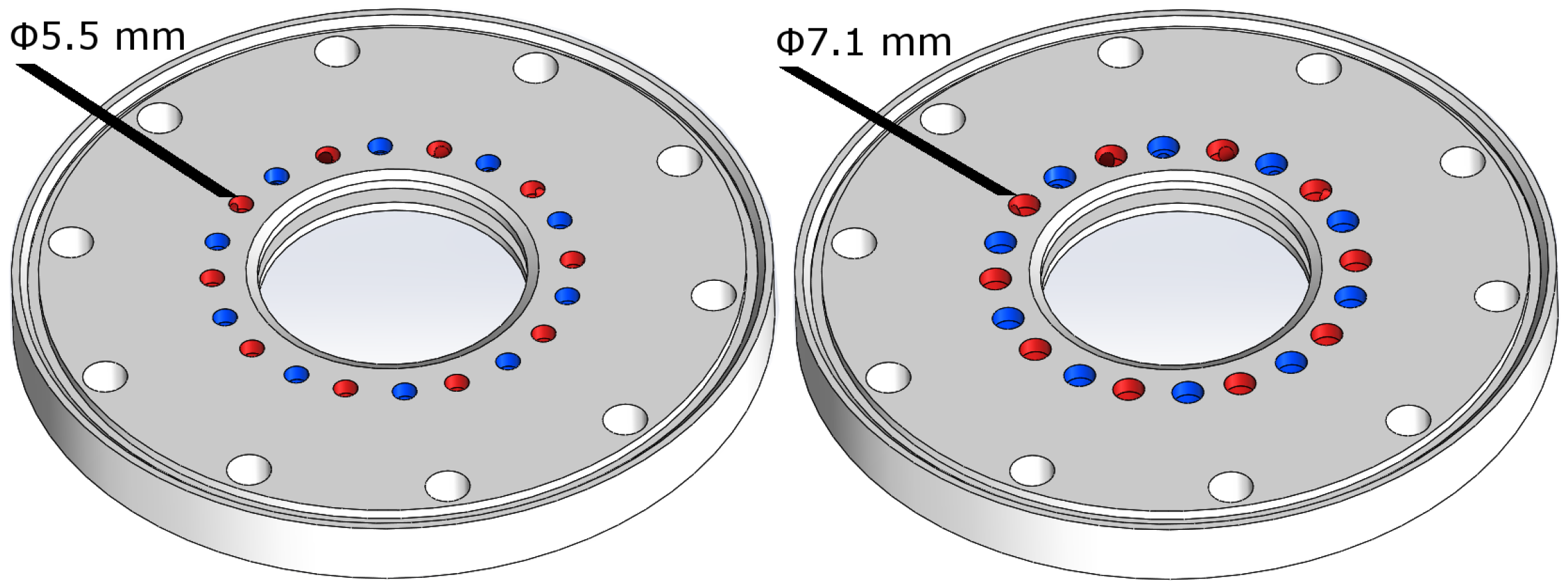
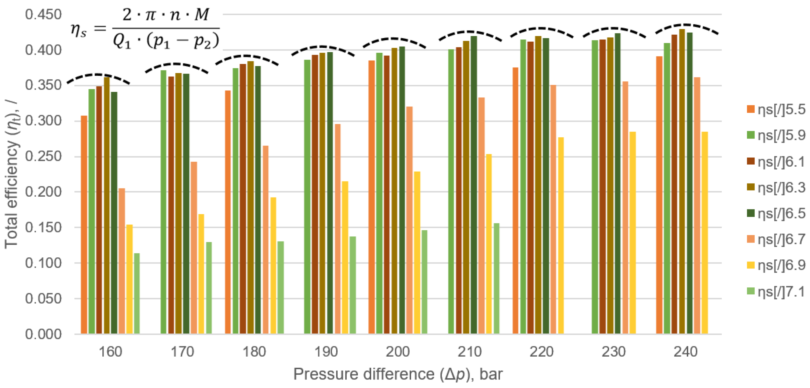
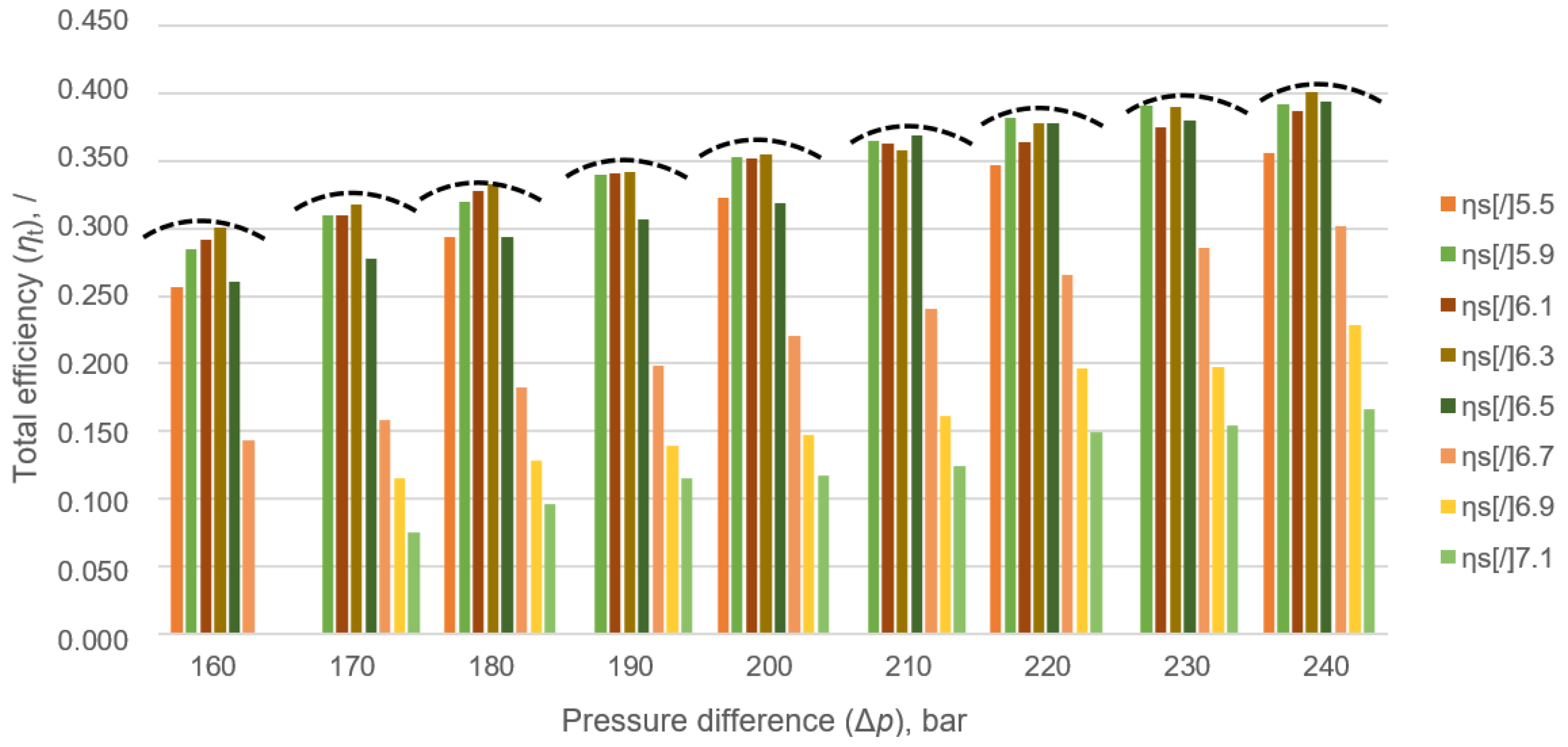
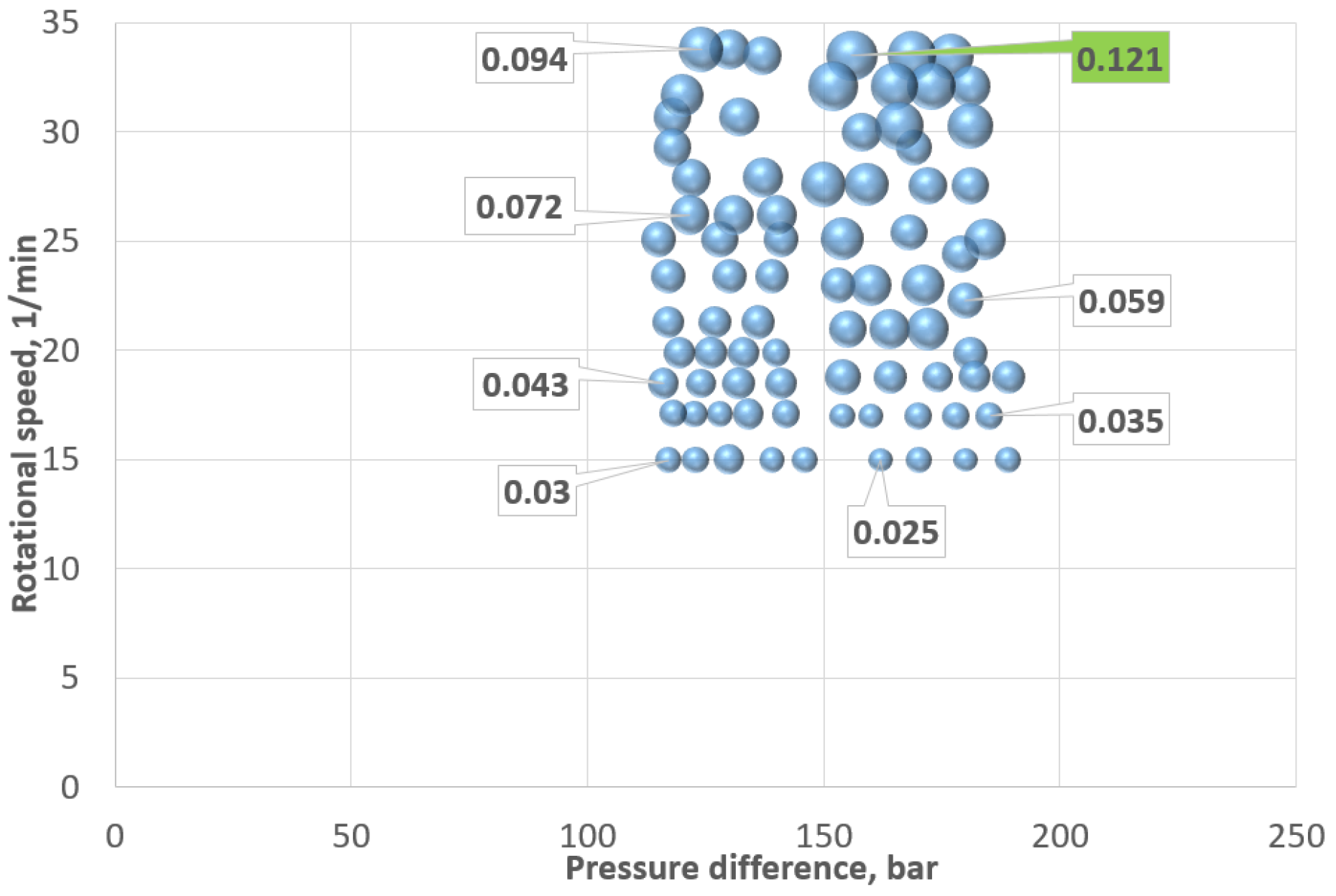
  • The size of the holes in the valve plate influences the total efficiency of the gerotor. It can be increased with a very basic mechanical operation, such as drilling. Total efficiency was increased on average by 5% when we tested a hole size of ϕ 6.3 mm instead of a hole size of ϕ 5.5 mm (original size).
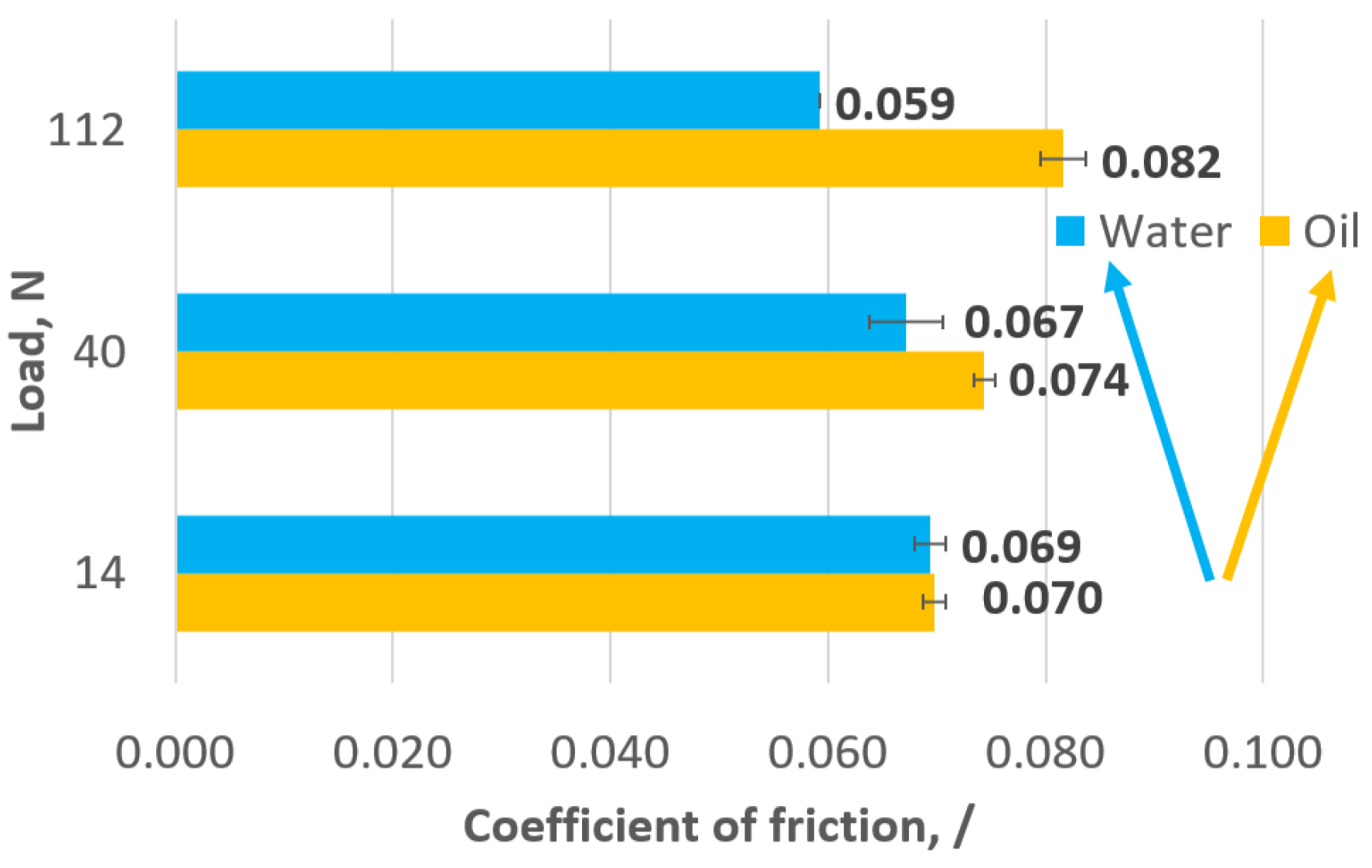
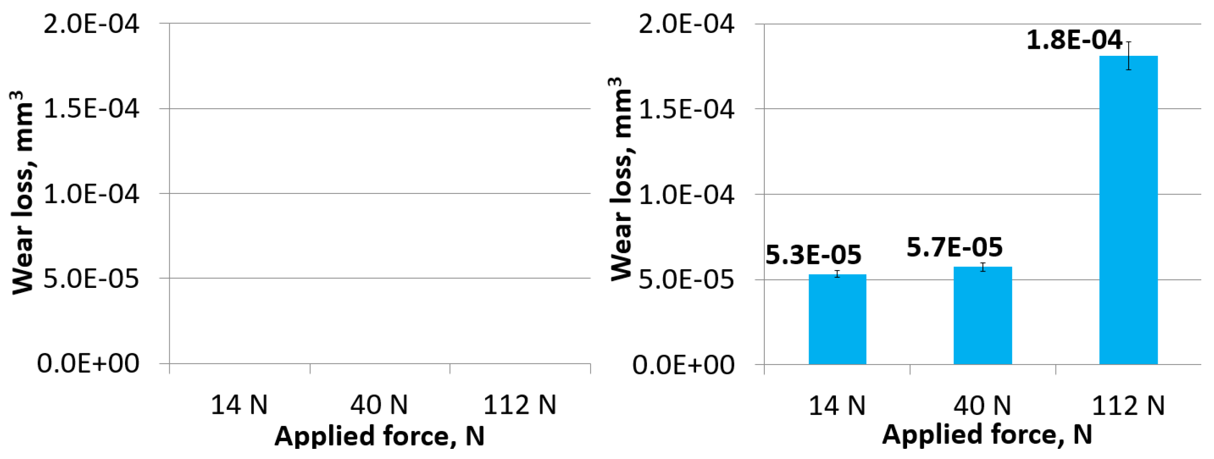
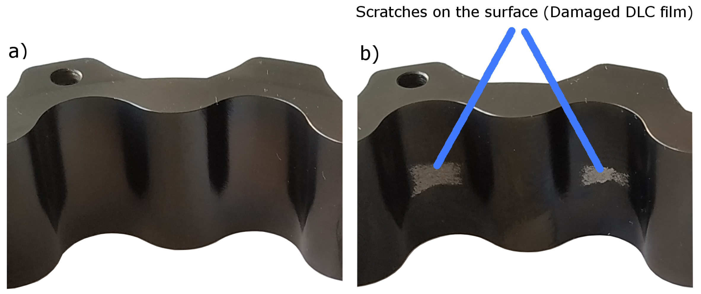
  • Very promising tribological behavior was observed when the steel/DLC contact was tested in water. It was proven that the friction of the steel/DLC contact in water (0.065) was lower than the friction of the steel/DLC contact in oil (0.075). The wear loss of the discs was very low and, in some cases, almost unmeasurable.
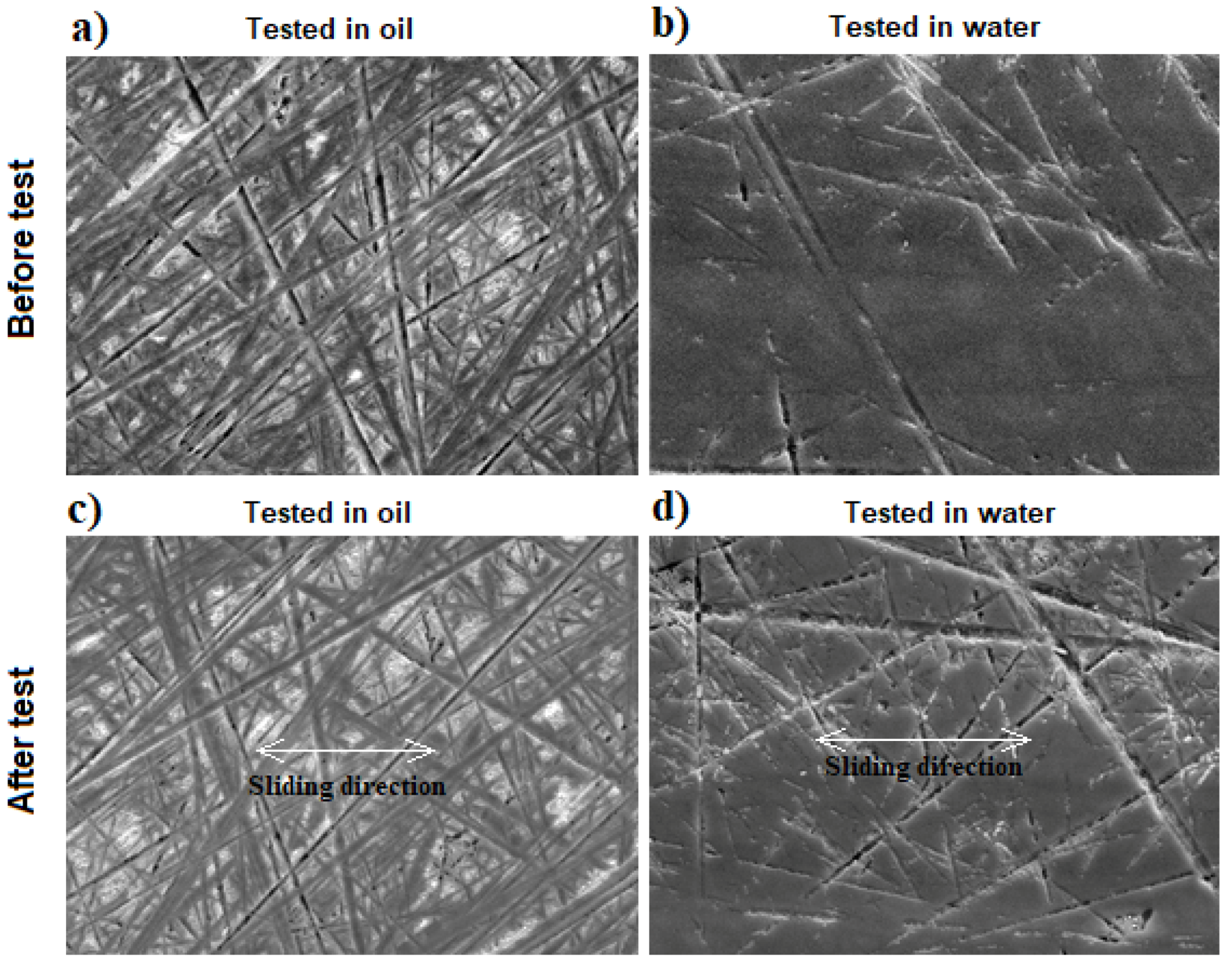
  • Surface analysis showed that there were almost no defects on worn surfaces, and this was in good agreement with the calculated wear coefficient.
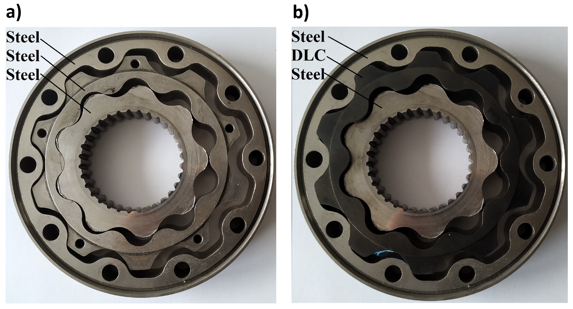
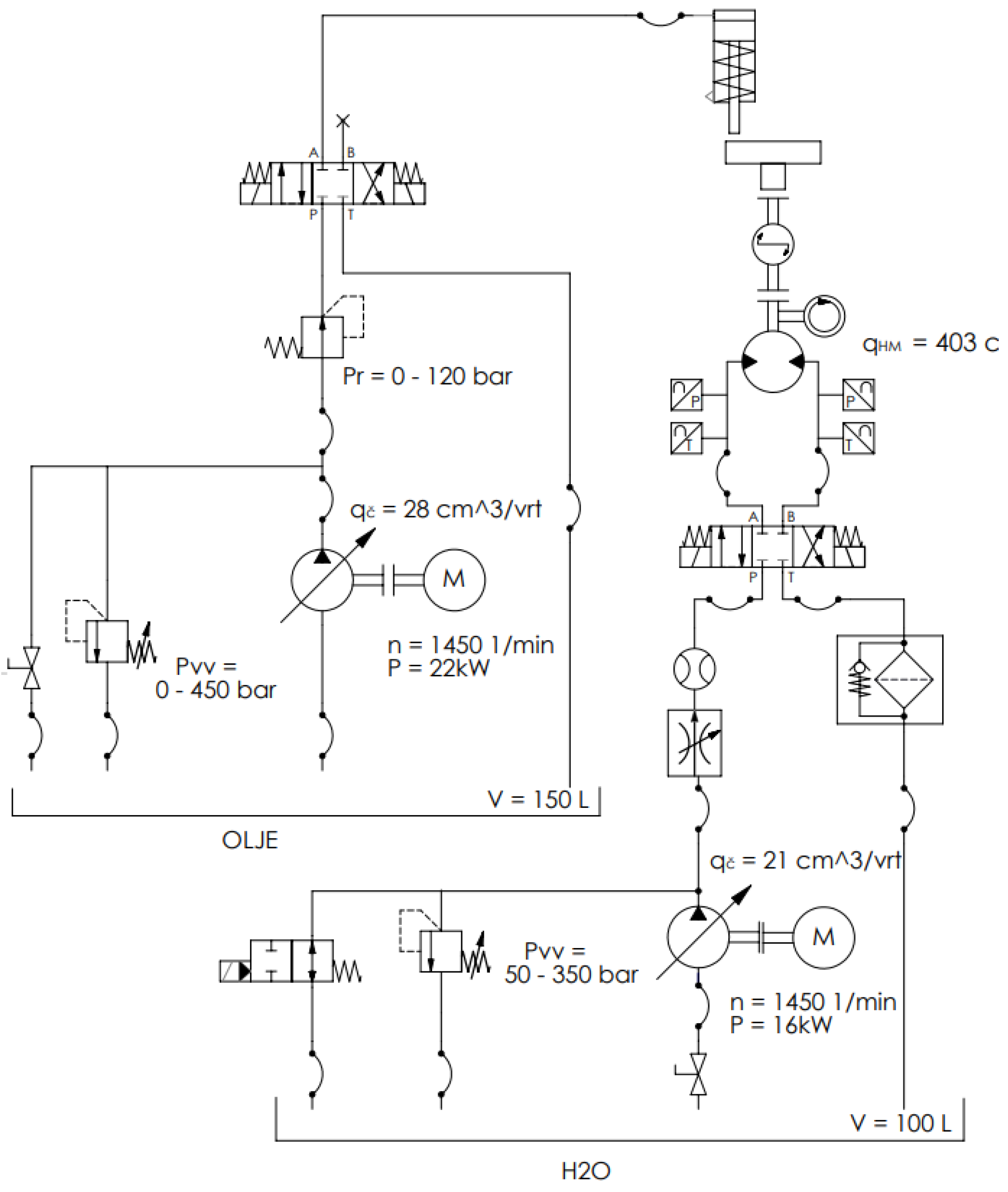
  • The original hydraulic motor, where all mechanical parts were made from steel, did not operate when water was used as the working fluid.
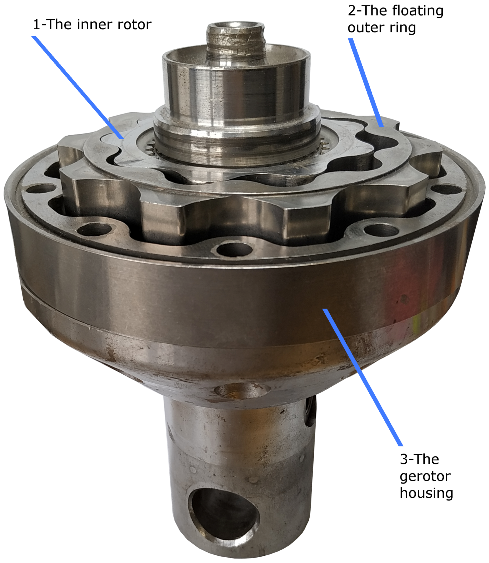
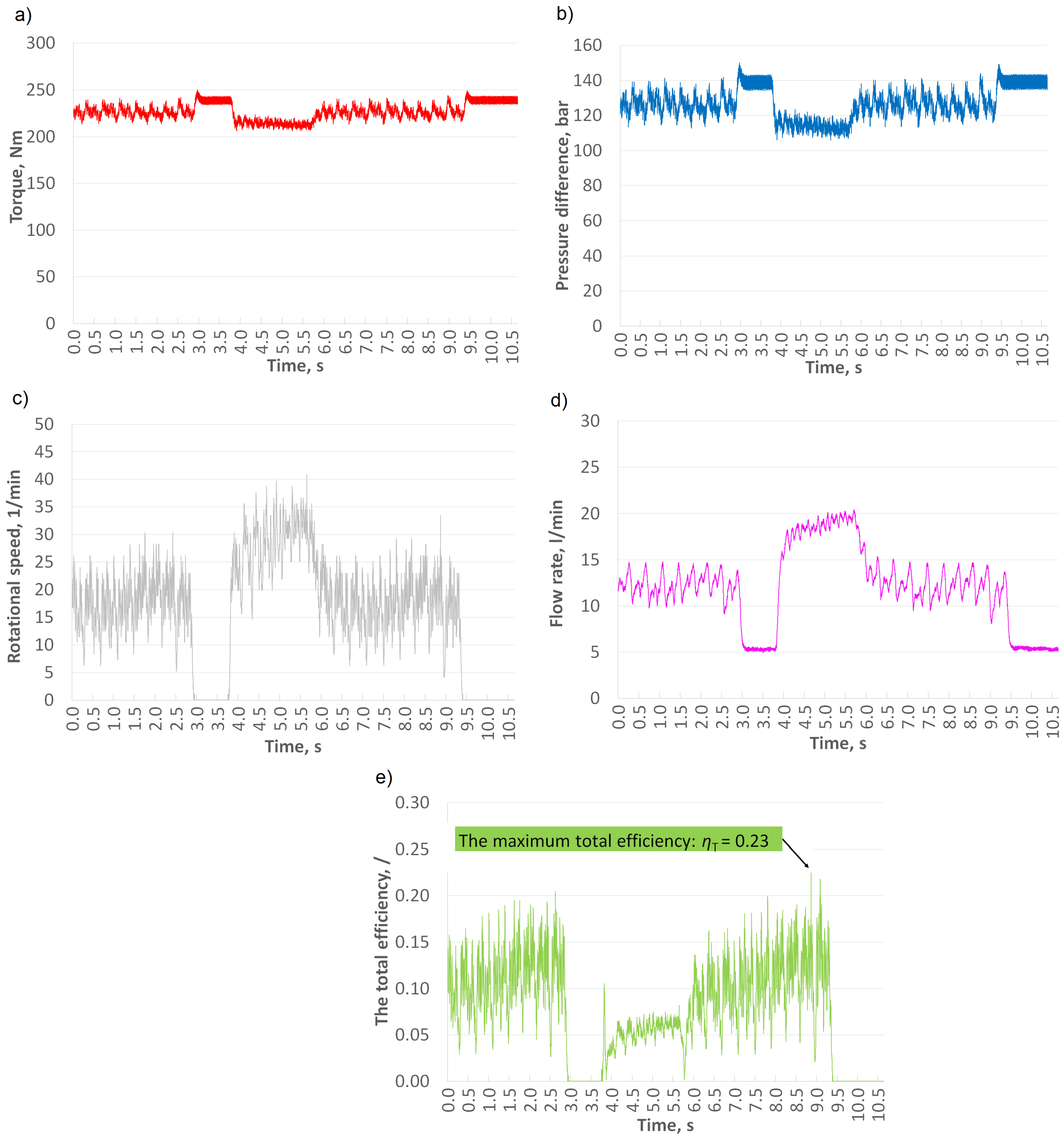
  • DLC was deposited onto the floating outer ring, so steel/DLC contacts were formed within the hydraulic motor between (a) the floating outer ring/the inner rotor, (b) the floating outer ring/the gerotor housing, and (c) the floating outer ring/the valve plate. Such a modified hydraulic motor achieved a total efficiency of up to 23%.

Author Contributions

Conceptualization, E.S., F.M., and M.K.; methodology, E.S., F.M., and M.K.; software, E.S.; validation, E.S., F.M., and M.K.; formal analysis, E.S.; investigation, E.S., F.M., and M.K.; resources, E.S., F.M., and M.K.; data curation, E.S.; writing—original-draft preparation, E.S.; writing—review and editing, E.S. and F.M.; visualization, E.S.; supervision, F.M. and M.K.; project administration, F.M. and M.K.; funding acquisition, E.S., F.M., and M.K.

Funding

This research was funded by Slovenian Research Agency ARRS (grant ID: 1000-18-0510).

Acknowledgments

The authors gratefully acknowledge support from the company KGL d.o.o., Slovenia, and the company Gazela d.o.o.

Conflicts of Interest

The authors declare no conflict of interest.

Nomenclature

The following symbols were applied:
k(mm3/Nm)Wear coefficient
n(1/min)Rotational speed
p(MPa)Pressure
q(cm3/rev)Displacement
s(mm)Stroke
f(Hz)Frequency
v(m/s)Sliding speed
F(N)Load
M(Nm)Torque
R a ( μ m)Surface roughness
Q(m3/s)Flow rate
S(m)Sliding distance
W(mm3)Wear loss
ν (mm2/s)Kinematic viscosity
η h m (/)Hydraulic-mechanical efficiency
η T (/)Total efficiency
η v (/)Volumetric efficiency

References

  1. Langsdorf, S. EU Energy Policy: From the ECSC to the Energy Roadmap 2050; Green European Foundation: Brussels, Belgium, 2011. [Google Scholar]
  2. Ivantysyn, J.; Ivantysynova, M. Hydrostatic Pumps and Motors: Principles, Design, Performance, Modelling, Analysis, Control and Testing; Tech Books International: New Delhi, India, 2003. [Google Scholar]
  3. Sang, X.; Zhou, X.; Liu, X. Performance optimization of an oil ellipse gerotor pump for automotive engine. In 5th International Conference on Advanced Design and Manufacturing Engineering; Atlantis Press: Paris, France, 2015. [Google Scholar] [Green Version]
  4. Bae, J.H.; Lee, H.R.; Kim, C. Optimal Design of Gerotor with Combined Profiles (Three-Ellipse and Ellipse-Involute-Ellipse) Using Rotation and Translation Algorithm. Trans. Korean Soc. Mech. Eng. A 2015, 39, 169–177. [Google Scholar] [CrossRef]
  5. Jacazio, G.; De Martin, A. Influence of rotor profile geometry on the performance of an original low-pressure gerotor pump. Mech. Mach. Theory 2016, 100, 296–312. [Google Scholar] [CrossRef]
  6. Dong, X. Multi-Objective Optimization Design of Gerotor Orbit Motors; Technical Report, SAE Technical Paper; SAE International: Warrendale, PA, USA, 2002. [Google Scholar]
  7. Ding, H.; Lu, X.; Jiang, B. A CFD model for orbital gerotor motor. In IOP Conference Series: Earth and Environmental Science; IOP Publishing: Bristol, UK, 2012; Volume 15, p. 062006. [Google Scholar]
  8. Mishev, A.; Stehle, T. CFD-Analyse zur Leistungssteigerung eines Orbit-Motors. Werkstattstech. Online 2015, 105, 433–439. [Google Scholar]
  9. Michael, P.; Burgess, K.; Kimball, A.; Wanke, T. Hydraulic Fluid Efficiency Studies in Low-Speed High-Torque Motors; Technical Report, SAE Technical Paper; SAE International: Warrendale, PA, USA, 2009. [Google Scholar]
  10. Conrad, F.; Trostmann, E.; Zhang, M. Experimental identification and modelling of flow and torque losses in gerotor hydraulic motors. In Proceedings of the JFPS International Symposium on Fluid Power; The Japan Fluid Power System Society: Tokyo, Japan, 1993; pp. 677–682. [Google Scholar]
  11. Garcia, J.M. Surface Effects on Start-Up Friction and Their Application to Compact Gerotor Motor Design. Ph.D. Thesis, Purdue University, West Lafayette, IN, USA, 2011. [Google Scholar]
  12. Furustig, J.; Almqvist, A.; Pelcastre, L.; Bates, C.A.; Ennemark, P.; Larsson, R. A strategy for wear analysis using numerical and experimental tools, applied to orbital type hydraulic motors. Proc. Inst. Mech. Eng. Part C J. Mech. Eng. Sci. 2016, 230, 2086–2097. [Google Scholar] [CrossRef]
  13. Ranganathan, G.; Raj, T.H.S.; Ram, P.M. Wear characterisation of small PM rotors and oil pump bearings. Tribol. Int. 2004, 37, 1–9. [Google Scholar] [CrossRef]
  14. Koskinen, K.T.; Leino, T.; RIIPINEN, H. Sustainable development with water hydraulics-possibilities and challenges. In Proceedings of the JFPS International Symposium on Fluid Power; The Japan Fluid Power System Society: Tokyo, Japan, 2008; pp. 11–18. [Google Scholar]
  15. Hauert, R. An overview on the tribological behavior of diamond-like carbon in technical and medical applications. Tribol. Int. 2004, 37, 991–1003. [Google Scholar] [CrossRef]
  16. Wang, Q.J.; Chung, Y.W. Encyclopedia of Tribology; Springer: Berlin/Heidelberg, Germany, 2013. [Google Scholar]
  17. Kim, H.J.; Kim, D.E. Water lubrication of stainless steel using reduced graphene oxide coating. Sci. Rep. 2015, 5, 17034. [Google Scholar] [CrossRef]
  18. Strmčnik, E.; Majdič, F. Comparison of leakage level in water and oil hydraulics. Adv. Mech. Eng. 2017, 9, 1687814017737723. [Google Scholar] [CrossRef]
  19. Smith, W.V. Material selection criteria for water lubrication. Wear 1973, 25, 139–153. [Google Scholar] [CrossRef]
  20. Vižintin, J. Tribology of Mechanical Systems: A Guide to Present and Future Technologies; American Society of Mechanical Engineers: New York, NY, USA, 2004. [Google Scholar]
  21. Cha, S.C.; Erdemir, A. Coating Technology for Vehicle Applications; Springer: Berlin/Heidelberg, Germany, 2015. [Google Scholar]
  22. Sato, T.; Besshi, T.; Sato, D.; Tsutsui, I. Effect of water based lubricants on wear of coated material. Wear 2001, 249, 50–55. [Google Scholar] [CrossRef]
  23. Velkavrh, I.; Kalin, M.; Vizintin, J. The performance and mechanisms of DLC-coated surfaces in contact with steel in boundary-lubrication conditions: A review. Stroj. Vestn. 2008, 54, 189–206. [Google Scholar]
  24. Kalin, M.; Vižintin, J. A comparison of the tribological behaviour of steel/steel, steel/DLC and DLC/DLC contacts when lubricated with mineral and biodegradable oils. Wear 2006, 261, 22–31. [Google Scholar] [CrossRef]
  25. Kalin, M.; Majdič, F.; Vižintin, J.; Pezdirnik, J.; Velkavrh, I. Analyses of the long-term performance and tribological behavior of an axial piston pump using diamondlike-carbon-coated piston shoes and biodegradable oil. J. Tribol. 2008, 130, 011013. [Google Scholar] [CrossRef]
  26. Uchidate, M.; Liu, H.; Iwabuchi, A.; Yamamoto, K. Effects of water environment on tribological properties of DLC rubbed against stainless steel. Wear 2007, 263, 1335–1340. [Google Scholar] [CrossRef]
  27. Yamamoto, K.; Matsukado, K. Effect of hydrogenated DLC coating hardness on the tribological properties under water lubrication. Tribol. Int. 2006, 39, 1609–1614. [Google Scholar] [CrossRef]
  28. Tokoro, M.; Aiyama, Y.; Masuko, M.; Suzuki, A.; Ito, H.; Yamamoto, K. Improvement of tribological characteristics under water lubrication of DLC-coatings by surface polishing. Wear 2009, 267, 2167–2172. [Google Scholar] [CrossRef]
  29. Ohana, T.; Wu, X.; Nakamura, T.; Tanaka, A. Formation of lubrication film of diamond-like carbon films in water and air environments against stainless steel and Cr-plated balls. Diam. Relat. Mater. 2007, 16, 1336–1339. [Google Scholar] [CrossRef]
  30. Ohana, T.; Suzuki, M.; Nakamura, T.; Tanaka, A.; Koga, Y. Tribological properties of DLC films deposited on steel substrate with various surface roughness. Diam. Relat. Mater. 2004, 13, 2211–2215. [Google Scholar] [CrossRef]
  31. Tanaka, A.; Suzuki, M.; Ohana, T. Friction and wear of various DLC films in water and air environments. Tribol. Lett. 2004, 17, 917–924. [Google Scholar] [CrossRef]
  32. Suzuki, M.; Tanaka, A.; Ohana, T.; Zhang, W. Frictional behavior of DLC films in a water environment. Diam. Relat. Mater. 2004, 13, 1464–1468. [Google Scholar] [CrossRef]
  33. Kano, M.; Yasuda, Y.; Okamoto, Y.; Mabuchi, Y.; Hamada, T.; Ueno, T.; Ye, J.; Konishi, S.; Takeshima, S.; Martin, J.; et al. Ultralow friction of DLC in presence of glycerol mono-oleate (GNO). Tribol. Lett. 2005, 18, 245–251. [Google Scholar] [CrossRef]
  34. Majdič, F.; Velkavrh, I.; Kalin, M. Improving the performance of a proportional 4/3 water–hydraulic valve by using a diamond-like-carbon coating. Wear 2013, 297, 1016–1024. [Google Scholar] [CrossRef]
  35. Sutton, D.; Limbert, G.; Stewart, D.; Wood, R. The friction of diamond-like carbon coatings in a water environment. Friction 2013, 1, 210–221. [Google Scholar] [CrossRef] [Green Version]
  36. Ronkainen, H.; Varjus, S.; Holmberg, K. Tribological performance of different DLC coatings in water-lubricated conditions. Wear 2001, 249, 267–271. [Google Scholar] [CrossRef]
  37. ISO 8426:2008—Hydraulic Fluid Power–Positive Displacement Pumps and Motors—Determination of Derived Capacity; ISO-Standards Catalogue; ISO: Geneva, Switzerland, 2017; pp. 1–14.
  38. Joint Committee for Guides in Metrology. Evaluation of Measurement Data—Guide to the Expression of Uncertainty in Measurement; Technical Report, Technical Report No. JCGM 100; International ISBN Agency: New Providence, NJ, USA, 2008. [Google Scholar]
  39. Tallian, T. On competing failure modes in rolling contact. ASLE Trans. 1967, 10, 418–439. [Google Scholar] [CrossRef]
Figure 1. Half-assembled orbital hydraulic motor.
Metals 09 00466 g001
Figure 2. Minimum ( ϕ 5.5 mm) and maximum ( ϕ 7.1 mm) hole size in the valve plate ( ϕ 174 mm × 15 mm).
Metals 09 00466 g002
Figure 3. Hydraulic circuit of the test rig for evaluating the performance of the oil-based orbital hydraulic motor.
Metals 09 00466 g003
Figure 4. Materials of the most important mechanical parts of the (a) original and (b) modified hydraulic motor.
Metals 09 00466 g004
Figure 5. Hydraulic circuit of the test rig for evaluating the performance of the water-orbital hydraulic motor.
Metals 09 00466 g005
Figure 6. Total efficiency (value in label) of the original hydraulic motor, with hole size in valve plate ϕ = 5.5 mm , tested in oil.
Metals 09 00466 g006
Figure 7. Total efficiency of hydraulic motor (n = 15 min−1).
Metals 09 00466 g007
Figure 8. Total efficiency of hydraulic motor (n = 17 min−1).
Metals 09 00466 g008
Figure 9. Coefficient of friction of SS/Diamond-Like Carbon (DLC) in oil and water.
Metals 09 00466 g009
Figure 10. Disc wear loss for SS/DLC in oil (Left) and water (Right).
Metals 09 00466 g010
Figure 11. Scanning electron microscope (SEM) image of the DLC-coated disc (a) before test in oil, (b) before test in water, (c) after test in oil, (d) after test in water.
Metals 09 00466 g011
Figure 12. Total efficiency (value in label) of the modified hydraulic motor, with hole size in valve plate ϕ = 5.5 mm , tested in water.
Metals 09 00466 g012
Figure 13. Experimental results of the modified hydraulic motor: (a) torque, (b) pressure difference, (c) rotational speed, (d) flow rate, and (e) total efficiency.
Metals 09 00466 g013
Figure 14. Surface appearance on the inner side of the floating outer ring (a) before and (b) after the test.
Metals 09 00466 g014
Table 1. Results of uncertainty analysis.
Rectangular Distribution (%)Triangular Distribution (%)
Pressure1.501.06
Flow rate1.731.22
Torque2.021.43
Rotational speed1.731.22

