Article

Close Range Explosive Loading on Steel Column in the Framework of Anisotropic Viscoplasticity

by
Piotr Witold Sielicki
*,
Wojciech Sumelka
and
Tomasz Łodygowski
Institute of Structural Engineering, Poznan University of Technology, Piotrowo 5 street, 60-965 Poznan, Poland
*
Author to whom correspondence should be addressed.
Metals 2019, 9(4), 454; https://doi.org/10.3390/met9040454
Submission received: 12 March 2019 / Revised: 7 April 2019 / Accepted: 11 April 2019 / Published: 17 April 2019
(This article belongs to the Special Issue Metallic Materials under Dynamic Loading)

Abstract

:
The research was based on data obtained from experimental studies and aims in the challenge of mapping these results by a mathematical (phenomenological) model. The field experiments were performed on an H-section steel column supported by a reinforced concrete foundation and subjected to a close-in explosion. Numerical studies were carried out using Abaqus/Explicit code. The user subroutine VUMAT for metallic obstacle was also implemented, together with a coupled Eulerian–Lagrangian approach. The steel column failure recorded during real field tests versus computational results was examined and compared. It was crucial that, from the computational point of view, the obstacle reflected the generalized thermo-elasto-viscoplastic (GTEV) behavior of Perzyna’s type, including an anisotropic measure of damage.

1. Introduction

Today, the threat of the incidental events, especially in the civil engineering structures, is relatively high. Due to this fact, personal safety is under special consideration by government administration. These scenarios deal with buildings like airports, shopping centres, and others, where the people throughput is above standard expectations of designers. The latter continually increase floor areas and obtain more and more spans of ceilings. For that reason, the supporting boundaries, such as columns or walls, must be designed and constructed to withstand unique events, e.g., incidental explosive loading or terrorist attacks. Therefore, material strength and design must be beyond standard engineering approach and take into account advanced theories and methodologies [1,2].
In recent decades, many researchers focused on conducting sophisticated analyzes of structural elements, subjected to extraordinary dynamic loads. Nassr et al. [3] proved that commonly used standards [4], more often than not, overestimate the results. Their research considers a numerical material model of a steel column, in LS-DYNA, that includes plasticity and strain-rate effect. Sabuwala et al. [5] analyzed a steel column in Abaqus/Explicit. They used elastic-plastic material properties with isotropic hardening for the obstacle. The blast loading was applied as uniformly distributed load to the inner faces of the column. They introduced a solid geometry of the structure, however, using coarse mesh only (three solid finite elements on the elements thickness). Moreover, a spatial geometry of welds was analyzed. Nevertheless, the calibration of the model allowed for correct prediction of the experimental outcomes. Rigby et al. [6] considered a plate under blast pressure. The loading was realised by a modified Friedlander equation. The obstacle description was reflected by the elastic-plastic steel behavior. They quantified the effect of blast wave clearing on elasto-plastic systems via rigorous analysis of elasto-plastic as one degree of freedom systems. Moreover, the dynamic equation of motion was solved using the explicit scheme for equivalent single degree of freedom (SDOF) systems (the authors compared the results with the numerical ones performed by the LS-DYNA software). Finally, they used a different piece-wise force-time function applied to the SDOF model. Neuberger et al. [7] modeled the behavior of steel plate using a rate-sensitive, elastic–plastic bi-linear material, employing Huber–Hencky–Mises yield criterion. Strain-rate effects were considered based on the Cowper–Symonds model. The explosive loading was generated using built-in CONWEP function in the LS-DYNA. Furthermore, the peak transient and the residual deflections were compared for a clamped circular armor steel plate subjected to large close-range spherical air-blast loading. They also presented the experimental results from a series of controlled explosions and finite elements calculations. Makarem et al. [8] analyzed a steel column under rigid impact in Abaqus/Explicit. They implemented the Voyiadjis–Abed model for steel in VUMAT user subroutine. In addition, they investigated the effect of impact velocity, impactor mass, impact location, and pre-loading condition on the localization behavior of the steel columns. Finally, they compared the results with the Johnson–Cook (JC) phenomenological model, implemented in Abaqus. The adiabatic localization’s of intense plastic strains and heats were investigated throughout the flange width, flange length, web depth, and web length. Denny et al. [9] experimentally analyzed the response of the steel H-section column, for long-duration and long-range explosive loading. A series of experiments were done under different rotation angles of the obstacle. Fu et al. [10] experimentally and numerically verified the behavior of a scaled steel shell building caused by an internal explosion. In the finite element method (FEM) analysis, they took into account the default (JC) material description for Q235 steel using the LS-DYNA. Another comprehensive study on the H-section steel column was done by Hadianfard et al. [11]. They used a default LS-DYNA material model suited to describe isotropic and kinematic hardening plasticity with the potential of inclusion of strain-rate effects. In this description, the high strain-rate effect was involved based on the Cooper–Simonds relationship. A study completed by Malachowski [12] dealt with the same structure mentioned in this paper. However, the LS-DYNA software was applied, and the steel H-section was modeled as the shell strenghthened by the aluminium foam shield system. Moreover, steel behavior was described by the built-in JC material model.
Based on the above state-of-the-art studies, it appears that close-in blast loading on a metallic obstacle is rarely modeled using advanced constitutive models—especially those mapping the anisotropic behavior. Therefore, the filling of this gap plays a fundamental role in the presented considerations and simultaneously states the paper’s most original part. Moreover, one can point out the following aspects which make the modeling in terms of the generalized thermo-elasto-viscoplastic (GTEV) unique: (i) invariance with respect to any diffeomorphism (covariant material model) [13], (ii) well-posedness of the evolution problem, (iii) sensitivity to the rate of deformation, (iv) finite elasto-viscoplastic deformations, (v) plastic non-normality, (vi) dissipation effects (anisotropic description of damage) [14], (vii) thermo-mechanical couplings, and (viii) implicit length scale sensitivity. On the other hand, it is important that the viscoplasticity theory, being a physical one, has a deep physical interpretation derived from the analysis of a single crystal and polycrystal behavior [15]. Furthermore, the application of GTEV [16] allows us to obtain two levels of the experimental results approximation, namely: global level (GL) (strain-stress curves fitting from experiment and mathematical model) and local level (LL) (global plus coincidence in macrodamage initiation time, velocity of macrodamage evolution, and the geometry of macrodamage pattern)—cf. [17], where extensive GTEV comparisons with JC [18] and Rusinek–Klepaczko [19] models are presented.
The research presented in this work consists of two main parts. The first (finite element modeling of the steel column) emphasizes the meaningful role of modern designing process, where initially one looks for optimal solution based on proper virtual model. The second part deals with validation based on the real field outcomes.

2. Constitutive Assumptions

2.1. Introductory Remarks

The explosive loading scenarios belong to high speed phenomena. Strain rate values in the loaded material are 10 3 1 / s or even 10 7 1 / s. Temperatures can be as high as melting point. The final failure of the structure may occur in 0.001 seconds. Typical blast loading is often modeled as an uncoupled process, i.e., one considers separately thermal and force effects. However, only the second one is highly important considering the behavior of a structural safety under explosion of a condensed charge. This kind of loading represents rapid pressure changes in time. Furthermore, blast pressure consists of two significantly different phases, positive and negative.
The typical time-history change of blast overpressure in free air is shown in Figure 1, where P is the overpressure, also called the air blast pressure, and t is the time. The virtual point of measurement is separated from the charge centre, and is located in a particular distance called stand-off.
When the process is initiated, following the explosion at the time of arrival t a , the pressure suddenly increases to a peak value P SO , which exceeds the ambient pressure P 0 . Next, the pressure decays to P 0 in time t 0 , and afterwards reaches P SO pressure to finally reach again the atmospheric pressure, at time t 0 . The sum of times of over- and under- pressures is called the time of duration T. The value of P SO is usually referred to as the peak side on overpressure or incident peak overpressure, and remains according to the established rules [21]. All these parameters were initially presented in 1870 by Rankine and Hugoniot [22].
The knowledge about the instantaneous pressure changes and the duration of the positive phase allows us to calculate the blast impulse of an explosion. It should be emphasized that the positive phase and its impulse is highly important for the analysis of structural strength of any kind of obstacle.
From the point of view of modeling, one can highlight three important aspects: modeling of charge, modeling of surrounding air, and modeling of loaded obstacle, which in this paper, is represented by the H-section steel column. The description of those three stages are summarized below, for more details refer to [23,24].

2.2. Description of the Surrounding Air and the Condensed Charge

The governing equations which are necessary to describe the blast waves and explosion are complex. Since it is not possible to obtain the analytical solution of spatial explosion phenomena, researchers turn towards numerical approach, e.g., to the finite element modeling as a highly elaborated tool for solving blast problems (as in the presented paper). One of the first attempts to solve this problem was presented by Brode [25] and afterwords verified numerically by Kingery [26].
So, the phenomena of the fluid flow is governed by the Navier–Stokes type equation in the form ( · v 0 and ρ c o n s t . ):
ρ v ˙ + p η 2 v η 3 ( · v ) = ρ b ,
where ρ is the fluid density, v denotes the velocity of fluid particle, ∇ stands for the nabla operator, p denotes the pressure, η is the fluid viscosity, and b denotes the body force. The pressure p has the general form:
p = p ( ρ , E ) ,
where E is the internal energy per unit mass, whereas the deviatoric stress τ has to fulfill the following relation:
τ = 2 η e ˙ ,
where e denotes the strain deviator. Furthermore, the conservation of energy (in the absence of heat conduction) provides the last equation, namely:
ρ E ˙ = p ρ ρ ˙ + τ : e ˙ + ρ Q ˙ ,
where Q ˙ is the heat rate per unit mass (by default adiabatic conditions are assumed [27]). Furthermore, the following initial conditions:
v ( x , 0 ) = v 0 , x Γ f ,
E ( x , 0 ) = E 0 , x Γ f ,
p ( x , 0 ) = 0 , x Γ f ,
ρ ( x , 0 ) = ρ 0 , x Γ f ,
and the boundary conditions (no slip):
v ( x , t ) = 0 , x Γ f ,
holds, where x stands for spatial coordinates, Γ f is the fluid volume, and Γ f denotes the fluid boundary.
Hence, the description of the surrounding air assumes an the ideal gas (IG) law for pressure p a i r , namely:
p a i r + p a = ρ R ( T T z ) ,
where p a is the ambient pressure, ρ is the current air density, R is the universal gas constant, T is the current temperature and T z is the absolute zero temperature (the value of the atmospheric pressure represents perfect laboratory conditions).
Finally, for the condensed charge the equation of the state proposed by the Jones–Wilkins–Lee (JWL) model [27,28,29,30,31,32] is adopted, namely:
p c h = A 1 w ρ c h R 1 ρ 0 exp R 1 ρ 0 ρ c h + B 1 w ρ c h R 2 ρ 0 exp R 2 ρ 0 ρ c h + ω ρ c h E ,
where A, B, R 1 , and R 2 , are material constants [28,33], and ρ c h is the current density of detonation product. The initial ratio of ρ c h to ρ 0 used in the JWL equation is assumed to be unit. Nonetheless, one should notice that proper understanding of JWL limitations, especially for close range explosive loading, is still an open task cf. [34,35,36].

2.3. Behavior of the Steel Column

Explosive loading induces a thermomechanical process in the obstacle [37]. This process is extremely fast and considerably influenced by the wave effects [38]. Formal description of such processes, within the continuum mechanics framework, leads to very complex models, with a huge number of material parameters [17,39,40]. It is clear that identification/calibration of such models needs many sophisticated experimental tests under different loading rates and temperatures levels [41,42,43].
In this paper, the metallic obstacle ws modeled in the framework of Perzyna’s type viscoplasticity accounting for anisotropic damage description. It is important to emphasize that although the Perzyna model is commonly associated with famous definition of rate of viscoplastic strains in terms of overstress function only, in its present form it belongs to the most general and elegant formulations in mechanics [16,44].
Below, the fundamentals of Perzyna’s type viscplasticity are presented to make the paper self-contained. For comprehensive description, the reader should follow recent papers in this field, e.g., [13,14,16,24,45].
The constitutive model is stated in terms of continuum mechanics along with a phenomenological approach. The constitutive structure reflects the class of simple materials with fading memory and belongs to the material models of rate type with internal state variables [46,47]. The description applies the macro (meso-macro) scale of observation, therefore all variables in the model, reflect the homogenised reaction from smaller scales of observations [48]. Moreover, multiscale effects are included through the state variables. The already mentioned length scale sensitivity is incorporated implicitly through the relaxation time of mechanical disturbances.
In theory, real body is represented by the abstract body which is modeled as a differential manifold. We assume that finite elasto-viscoplastic deformations of a body are governed by the multiplicative decomposition of the total deformation gradient to elastic and viscoplastic parts [49,50]:
F ( X , t ) = F e ( X , t ) · F p ( X , t ) or F A a ( X A , t ) = F e A b ( X A , t ) F p b a ( X A , t ) E A e a ,
where F = ϕ ( X , t ) X denotes the total deformation gradient (or F A a ( X A , t ) = ϕ a X A ( X A , t ) E A e a , where E A and e a are base vectors in material and spatial descriptions, respectively), ϕ describes the motion, X = { X A } denotes the material coordinates, t is time, and F e , F p are elastic and viscoplastic parts, respectively.
All rates in the model are expressed using Lie derivative, therefore the formulation holds the spatial covariance [47,51,52]. In consequence, the symmetric part of spatial deformation gradient is directly Lie derivative of the Euler–Almansi strain, namely:
d = L υ ( e ) or d a b = 1 2 g a c υ c | b + g c b υ c | a e a e b ,
and simultaneously:
d e = L υ ( e e ) , d p = L υ ( e p ) ,
where L υ stands for Lie derivative, υ is the material point velocity, e is the Euler–Almansi strain, and the metric tensor components are defined as g a b ( x a ) = ( e a , e b ) , x a (the notation ( · ) , x a means the inner product in the spatial configuration, and recall that x = { x a } stands for the spatial coordinates). In other words, d truly describes the strain rate.
Next, we assume that the conservation of mass, the balance of momentum, the balance of moment of momentum, the balance of energy, and the entropy production inequality are satisfied. Nonetheless, to obtain the explicit form of material model four constitutive postulates are needed [15]:
(i)
Existence of the free energy function ψ . Formally, we apply the following form (cf. [53] for extensive discussion on such an assumption):
ψ = ψ ^ ( e , F , ϑ ; μ ) ,
where μ denotes a set of internal state variables which describe the dissipation effects and ϑ is temperature.
(ii)
The axiom of objectivity (spatial covariance). The material model should be invariant with respect to any superposed motion (diffeomorphism).
(iii)
The axiom of the entropy production. For every regular process the constitutive functions should satisfy the second law of thermodynamics.
(iv)
The evolution equation for the internal state variable vector μ should be of the form:
L υ μ = m ^ ( e , F , ϑ , μ ) ,
where evolution function m ^ has to be determined based on the experimental observations.
It should be pointed out that for qualitative and quantitative results considering blast acting on a real size metallic structure, it is enough to assume two state variables. We have:
μ = { p , ξ } or μ = { p , ξ a b e a e b } ,
where p is the equivalent plastic deformation p ˙ = 2 3 d p : d p 1 2 = 2 3 d a b p d a b p 1 2 , which describes the dissipation effects generated by viscoplastic deformation, and ξ is the microdamage tensor which takes into account the anisotropic microdamage effects. Because ξ is a second ordered tensor it keeps the information about damage direction, damage plane, and porosity [16]. Finally, for explicit statement of a complete set of governing equations, we assume adiabatic conditions, and moreover, we state that: Microdamage does not considerably influence the elastic range, and in every material point of the body there exists an initial microdamage state (cf. [15,24,54,55,56]).
The initial boundary value problem (IBVP), for the above assumptions, is then governed by the following rules. Find ϕ , υ , ρ , τ , ξ , ϑ as functions of t and position x such that [24,57,58]:
(i)
the field equations:
ϕ ˙ = υ , υ ˙ = 1 ρ R e f div τ + τ ρ · grad ρ τ 1 ( ξ : ξ ) 1 2 grad ( ξ : ξ ) 1 2 , ρ ˙ = ρ div υ + ρ 1 ( ξ : ξ ) 1 2 ( L υ ξ : L υ ξ ) 1 2 , τ ˙ = L e : d + 2 τ · d L t h ϑ ˙ ( L e + g τ + τ g ) : d p , ξ ˙ = 2 ξ · d + g * τ 1 T m Φ g [ I g τ e q ( ξ , ϑ , p ) 1 ] , ϑ ˙ = χ * ρ c p τ : d p + χ * * ρ c p k : L υ ξ ,
(ii)
the boundary conditions:
(a)
displacement ϕ is prescribed on a part Γ ϕ of Γ ( B ) and tractions ( τ · n ) a are prescribed on a part Γ τ of Γ ( B ) , where Γ ϕ Γ τ = 0 and Γ ϕ Γ τ = Γ ( B ) ,
(b)
heat flux q · n = 0 is prescribed on Γ ( B ) , and
(iii)
the initial conditions ϕ , υ , ρ , τ , ξ , ϑ are given for each particle X B at t = 0 ,
are satisfied. Above we have denoted: ρ R e f a referential density, τ the Kirchhoff stress tensor, ρ a current density, L e an elastic constitutive tensor, L t h a thermal operator, g a metric tensor, g * τ the evolution directions for anisotropic microdamage growth processes, T m a relaxation time, I g a stress intensity invariant, τ e q the threshold stress, χ * , χ * * the irreversibility coefficients and c p a specific heat.
For the evolution problem (Equation (18)), we postulate the following:
  • The elastic range is isotropic and independent of microdamage state, thus (for more general setup cf. [24]):
    L e = 2 μ I + λ ( g g ) or ( L e ) a b c d = 2 μ I a b c d + λ g a b g c d e a e b e c e d ,
    where μ , λ are Lam e ´ constants.
  • The thermal expansion is isotropic, thus:
    L t h = ( 2 μ + 3 λ ) θ g or ( L t h ) a b = ( 2 μ + 3 λ ) θ g a b e a e b ,
    where θ is the thermal expansion coefficient.
  • The rate of viscoplastic strains takes the form [16,59,60,61]:
    d p = Λ v p p or d a b p = Λ v p p a b e a e b ,
    where:
    Λ v p = 1 T m Φ v p ( f κ 1 ) = 1 T m ( f κ 1 ) m p l ,
    f = J 2 + n 1 ( ϑ ) + n 2 ( ϑ ) ( ξ : ξ ) 1 2 J 1 2 1 2 = J 2 + n 1 ( ϑ ) + n 2 ( ϑ ) ( ξ a b ξ a b ) 1 2 J 1 2 1 2 ,
    n 1 ( ϑ ) = 0 , n 2 ( ϑ ) = n = const . ,
    κ = κ s ( ϑ ) κ s ( ϑ ) κ 0 ( ϑ ) exp δ ( ϑ ) p 1 ( ξ : ξ ) 1 2 ξ F β ( ϑ ) = κ s ( ϑ ) κ s ( ϑ ) κ 0 ( ϑ ) exp δ ( ϑ ) p 1 ( ξ a b ξ a b ) 1 2 ξ F β ( ϑ ) ,
    ϑ ¯ = ϑ ϑ 0 ϑ 0 , κ s ( ϑ ) = κ s * κ s * * ϑ ¯ , κ 0 ( ϑ ) = κ 0 * κ 0 * * ϑ ¯ , δ ( ϑ ) = δ * δ * * ϑ ¯ , β ( ϑ ) = β * β * * ϑ ¯ .
  • The rate dependence of fracture porosity ξ F has the form [24]:
    ξ F = ξ F * ξ F * * ( | | L υ ξ | | | | L υ ξ c | | | | L υ ξ c | | ) m F ,
    where ξ F * can be thought of as a quasi-static fracture porosity and | | L υ ξ c | | denotes equivalent critical velocity of microdamage.
  • The normalised directions of viscoplastic flow, under the above assumptions, are defined as:
    p = f τ ξ = c o n s t f τ 1 = 1 [ 2 J 2 + 3 A 2 ( tr τ ) 2 ] 1 2 [ τ + A tr τ δ ] ,
    where τ represents the stress deviator, J 1 = τ a b g a b , J 2 = 1 2 τ a b τ c d g a c g c d are the first and the second invariants of Kirchhoff stress tensor and deviatoric part of the Kirchhoff stress tensor, respectively, A = 2 ( n 1 + n 2 ( ξ : ξ ) 1 2 ) = 2 ( n 1 + n 2 ( ξ a b ξ a b ) 1 2 ) .
  • The microdamage mechanism assumes the growth term only ( while nucleation is replaced by the initial microdamage distribution assumption), therefore taking the additional assumptions [16,62]: (i) Velocity of the microdamage growth is coaxial with the principal directions of the stress state, and (ii) only positive (tension) principal stresses induces the growth of the microdamage, one has:
    g * τ = g ^ τ g ^ τ 1 , and g ^ = 1 2 τ : G : τ ,
    Φ g I g τ e q ( ξ , ϑ , p ) 1 = I g τ e q 1 m g ,
    τ e q = c ( ϑ ) ( 1 ( ξ : ξ ) 1 2 ) ln 1 ( ξ : ξ ) 1 2 2 κ s ( ϑ ) κ s ( ϑ ) κ 0 ( ϑ ) F ( ξ 0 , ξ , ϑ ) = c ( ϑ ) ( 1 ( ξ a b ξ a b ) 1 2 ) ln 1 ( ξ a b ξ a b ) 1 2 2 κ s ( ϑ ) κ s ( ϑ ) κ 0 ( ϑ ) F ( ξ 0 , ξ , ϑ ) ,
    c ( ϑ ) = const . ,
    F = ξ 0 1 ξ 0 1 ( ξ : ξ ) 1 2 ( ξ : ξ ) 1 2 2 3 δ + 1 ( ξ : ξ ) 1 2 1 ξ 0 2 3 δ =
    ξ 0 1 ξ 0 1 ( ξ a b ξ a b ) 1 2 ( ξ a b ξ a b ) 1 2 2 3 δ + 1 ( ξ a b ξ a b ) 1 2 1 ξ 0 2 3 δ ,
    I g = b ¯ 1 J 1 + b ¯ 2 ( J 2 ) 1 2 + b ¯ 3 ( J 3 ) 1 3 ,
    where b ¯ i ( i = 1 , 2 , 3 ) are the material parameters, and J 3 is the third invariant of deviatoric part of the Kirchhoff stress tensor.
  • The tensor G is a symmetric part of the fourth order unity tensor I [16]:
    G = I s , G a b c d = 1 2 δ a c δ b d + δ a d δ b c ,
    hence:
    g ^ = 1 2 τ I 2 + τ I I 2 + τ I I I 2 ,
    and:
    g ^ τ = g 11 τ I 0 0 0 g 22 τ I I 0 0 0 g 33 τ I I I ,
    where τ I , τ I I , τ I I I are the principal values of the Kirchhoff stress tensor.
  • Lastly, for temperature evolution, the following relation is considered:
    k = τ or k a b = τ a b .
As mentioned, the evolution problem (18) is well-posed [58,63,64]. The relaxation time T m acts as a regularization parameter, which introduces implicitly the length scale. Thus, as numerically proved [58,65], the above Cauchy problem has a unique and stable solution.

3. Numerical Prediction of Blast Effect on Steel Column

3.1. Introductory Remarks

As mentioned, the numerical results are obtained using the Finite Element Method in the framework of Abaqus/Explicit program together with self coding user subroutine for GTEV model. Both Lagrangian and Eulerian meshes are used in one analysis [35]. It should be emphasized that in Abaqus/Explicit the Eulerian implementation is based on the volume-of-fluid method [66,67]. Moreover, for the Lagrangian mesh C3D8R element (a general purpose linear brick element, with reduced integration) was applied, whereas for the Eulerian mesh EC3D8R element was used (multi-material linear brick element, with reduced integration, whose underlying mechanical response formulation is based on C3D8R element). Furthermore, through the whole analysis, the adiabatic conditions hold [37].
It is important that credible modeling of the pressure evolution in ambient air must include relatively high density of the Eulerian finite elements mesh. Moreover, the interaction of this (shock) pressure with the obstacle metallic structure must be obtained using integration times about nanosecond and lower. Furthermore, the size of the Eulerian elements must be of the order of the Lagrangian one used for steel column discretization for high accuracy.
Recall that the basics of the explosive action on the column structure include the following scenario:
  • After the ignition moment in the centre of the explosive, the combustion wave goes through the charge domain, and then releases a high amount of kinetic and thermal energies;
  • the transition phase generates a high pressure wave on the charge and ambient boundaries; and
  • finally, the pressure reaches the obstacle boundaries and induces the thermomechanical process within its bounds, which is of strong wave character.

3.2. Steel Column Modeling Assumptions

It is important to thoroughly describe the computational setup, including the action of the close-in explosion on the H-section steel column and its failure. The general idea of the experiment is presented in Figure 2. The steel H-section dimensions are 300 × 300 mm 2 , while the thickness of the ledges equal to 10 and 20 mm, respectively. The column is fixed in the reinforce concrete basement 1000 × 1000 × 600 mm 3 . Moreover, the metallic obstacle is installed in the socket 400 mm beneath the top surface of the basement. The fixing is realised using four high-strength screws with trusses previously embedded inside the concrete block. Due to the experimental verification, the total height of the steel column is decreased to 1500 mm. This value reflects the part of the real structure, however, the pre-stressing vertical force is neglected (due to close-in TNT action). The shortened length of the column is also due to the fact that the reflected elastic wave inside the steel structure needs ca. 2 ms to come back to the loaded centre of the obstacle, whereas the failure time of the structure is below 1 ms. Therefore the length of the column is prepared well and in consequence the surrounded ambient domain including air and TNT charge, with the dimension 2500 × 2500 × 1750 mm 3 was assumed. It is clear that the limited size of the surrounded ambient domain simultaneously limits the total analysis time to the time when the flying fragments of damaged column reaches its boundaries.
The material properties for the explosive air, and the steel column are presented in Table 1 and Table 2, respectively. It should be noted that air properties were updated with the viscosity parameter which depends on the ambient temperature, see Reference [23].
The primary aim of computations was to obtain the deformation mode of the steel column under blast, including the fracture of the metallic material, crack pattern and mass and speed of the flying structure fragment. Because of the real size of the set-up, a challenging computational problem was obtained. The total number of finite elements was of the order 12 × 10 6 . This was because of, as reported in Reference [23], the critical size of an Eulerian element, (5 mm for the air domain that transfers the blast loading) the scaled distance was about 1.5 m × kg 1 / 3 for stand-off distance lower than 0.5 m. These assumptions were assumed for the air space between the obstacle and the charge. Concluding, the number of finite elements was: ca. 8.2 × 10 6 Eulerian elements (in Abaqus notation EC3D8R) to simulate the ambient and explosive domains and ca. 3.8 × 10 6 for the rigid basement and metallic obstacle (in Abaqus notation C3D8R). Moreover, in order to neglect the effects of reflection from the boundaries of the air domain, a special purpose boundary conditions were applied to the outer faces. This approach allowed us to simulate, approximately, the infinite ambient medium.
According to a standard engineering approach [20], we had assumed that the damage of the column would occur in ca. 0.7 ms after the detonation, while the arrival time of the blast wave front would be below ca. 0.1 ms.
As mentioned, the coupling of the Eulerian mesh and the Lagrangian mesh utilised the Coupled-Eulerian-Lagrangian (CEL) feature, available in the Abaqus/Explicit solver [27]. Furthermore, the ignition time was fixed to 1 ns whereas the incremental times were different and could be divided into two credible sets. The first, when the blast wave goes through the air domain, was about 10 8 s. The second was 10 13 s, in which the stress waves go through the metallic obstacle.

3.3. Results

Figure 3 amd Figure 4 present the numerical results. All fundamental computational fields are shown, namely: Figure 3A–D gives equivalent plastic strains; temperature; norm of porosity tensor—porosity; and thermal stresses, respectively, whereas in Figure 4A–C makes visible the displacements, Huber–Mises–Hencky stresses, and air pressure, respectively. It should be noted that apart from air pressure, which is shown for every simulation time step 0.1 ms, all fields are presented for the simulation times 0.1 , 0.2 , 0.5 , and 0.7 ms. This selected time sequence represents the following events: the first contact of the blast pressure with the metallic obstacle, strain localization in the metallic obstacle—formation of the flying fragment, evolution of damage in the strain localization zones, and full separation of the flying fragment.
The analysis of Figure 3 and Figure 4 allows us to formulate the following conclusions (these results are generally unattainable in the experiment):
  • High quality of the numerical results symmetry is observed,
  • equivalent plastic strains are locally as high as ca. 200 % in the strain localization zones,
  • the temperature in the strain localization zones is as high as ca. 800 C,
  • the evolution of the porosity is restricted to the zones of high plastic strains,
  • thermal stresses can be locally as high as 2000 MPa or more,
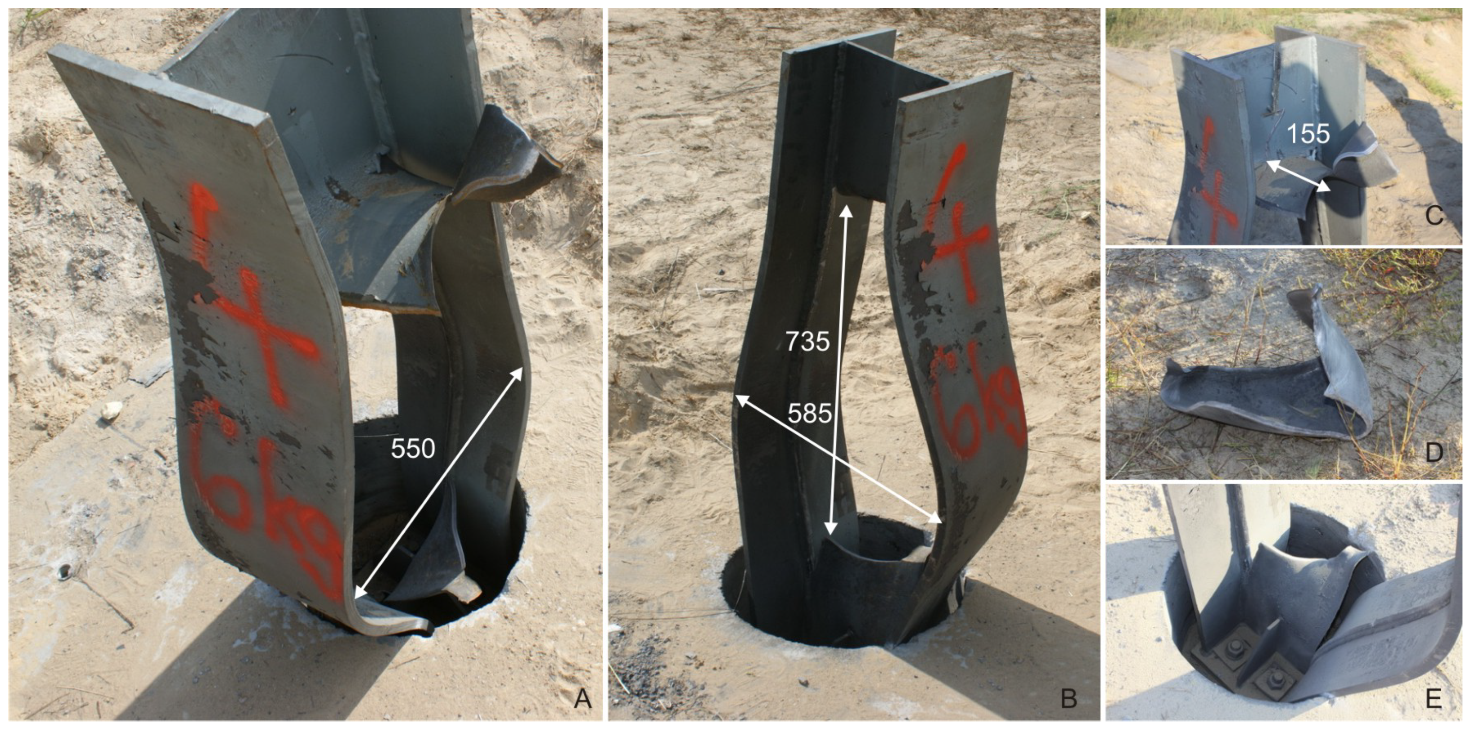
  • the displacement field is localised in the zone of the evolving flying fragment, whereas in the remaining part for t = 0.7 ms reaches ca. 0.23 m,
  • the strain hardening causes the Huber–Mises–Hencky stresses to be as high as ca. 900 MPa, and
  • air pressure is highly scattered in the fluid domain and reaches locally 150 MPa (161 MPa according to the standards cf. [20]).
Other important results, which are to some extent available from the real field experiment, are connected with the analysis of the velocity of the blast wave just before reaching the obstacle, and velocity and range of the flying fragment. So, the velocity of the blast wave is measured based on the velocity in the integration point of the E3D8 finite element. This reference point was located 0.266 m above the top surface of the foundation and 0.01 m before the structure, and is presented in Figure 3. Herein, the maximum velocity equals 3952 ms 1 (for the overpressure reaching 129 MPa).
For a flying steel fragment, its velocity and energy are most important for the final estimation of range of such debris. It appeared that 0.7 ms after the explosion, a flying fragment with weight of 4.788 kg and peak velocity of 486 m/s was formed. This value of velocity was reached, after the acceleration process. In the presented case, this velocity was measured at 0.34 m distance from the structure. Introducing basic horizontal projection formula for the initial conditions presented above, i.e., the initial velocity and height of the middle point of the structure, one can estimate the range for such fragment as ca. 138 m. Moreover, the calculated maximum kinetic energy for a flying steel fragment was more than 0.56 MJ.
Finally, high quality of the results is proved by the analysis of the material removal value from the FE model (measured by the percentage number of deleted elements). In the presented example, it was only 0.37 % of the total steel H-section mass—such sharp damage has been also observed experimentally, as will be presented in the next section. Moreover, for completeness, the energy balance for the total FEM model was controlled, and it was almost constant during the whole numerical solution process.

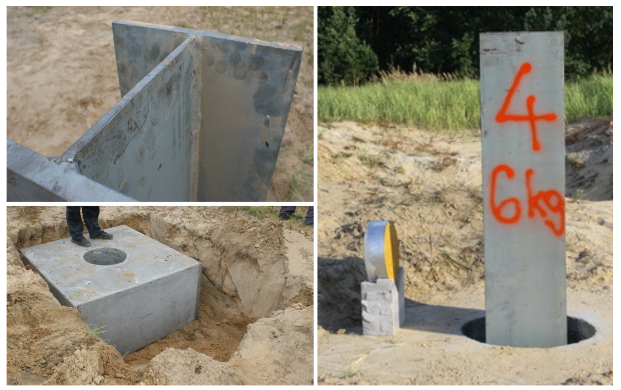
4. Experimental Validation

In a real design and actual verification process of any civil engineering structure under the explosion, an extensive and costly series of field experiments are needed, therefore, it is incredibly important to obtain a characteristic of the behavior of a particular structure through the numerical assessment.
In this study, selected comparative studies were performed during field tests. The actual experimental setup was prepared strictly in agreement with the previously presented assumptions for numerical analyzes, and repeated four times for the same scenario. For measurements, the following set-up was used:
  • High-speed camera Phantom v711 with mobile stand,
  • Bosch GLM 80 Professional Laser Rangefinder, and
  • ICP Free-field Blast Pressure “Pencil” Probe.
The real geometry of the four metallic columns and the location of the cylindrical explosives were according to Figure 2, as presented in Figure 5 and in agreement with the numerical model as mentioned. The main part of these studies focused on the action of close-in explosion of the TNT cylindrical charge. Due to above assumptions, the charge was placed in the 0.20 m stand-off distance from the frontal face of the H-section for each case. The centre of the cylindrical explosive was 0.40 m above the ground. The detonation was caused by the central ignition of the charge—which is crucial for the overall process. The steel column was fixed with four high strength screws in the real size basement, as shown in Figure 6E. This support prevented the boundary rotation. In this case, an external prestressing loading of the screws could be neglected. It should be noted that the blast loading, directed to the weaker axis of the steel profile, reflects the lower momentum of inertia.
The column has HKS-300-4 section with thicknesses equal to 20 mm and 10 mm for the ledges and the web, respectively. S355 steel was used to manufacture the column.
Because of the size of the fireball diameter, (estimated to be 8 m), it was not possible to record the failure and fragments velocity close to the structure. However, the actual values of critical range and mass of the flying fragment of the H-section web, for all four trials, were 90, 101, 110, 123 m and 5.5 , 5.8 , 5.9 , 6.8 kg, respectively. The actual mass of the fragment is a bit higher than in the FEM assessment. The primary reason is that in the actual structure the connection between the ledges and web was welded, whereas in the FEM model the material was assumed to be continuous neglecting any welds effects.
Next, it was not possible to directly measure pressures experimentally, because the stand-off distance was too close for the strength of the gauges. However, this limitation in the presented case study is not decisive. Namely, apart from high level of compatibility of the flying fragment behavior, the comparison of a final effect of the blast loading action on column Figure 6A,B with the computational one Figure 3 and Figure 4 shows high quality matching. Please notice that in the numerical simulations, as mentioned, the computational time was limited to 0.7 ms due to the maximum allowable size of the surrounded ambient domain, therefore the final (permanent) deformation of the computational steel column was proportionally smaller to the one observed in the experiment.

5. Conclusions

Despite significant efforts to clarify the mechanisms of blast loading at close-in distance, the possibilities of the researchers are limited. Experimental tests have been performed to present the destructive character of the explosive loading on the structural element, i.e., the steel column, and studied in the detailed numerical study.
In this study, the presented numerical approach gave high quality outcomes due to the application of the generalized thermo-elasto-vicsoplastic (GTEV) behavior of Perzyna type for the steel column, which is the most important part of reliable modeling. Global (strain-stress curves fitting from experiment and mathematical model) and local (global plus coincidence in macrodamage initiation time, velocity of macrodamage evolution, and the geometry of macrodamage pattern) levels of mapping were discussed in detail.
A crucial conclusion to be drawn from this research is that the equations of the state are suitable for the prediction of blast loads only if the size of the finite element was previously verified, and the mathematical modeling of the behavior of the obstacle takes into account highly advanced features. Otherwise, the numerical outcomes are limited and cannot predict the damage mode of the analyzed structure in detail, which is of crucial importance considering the impact that the broken parts of the blast loaded structure make on people or critical infrastructure.

Author Contributions

Conceptualization, P.W.S. and W.S. and T.Ł.; methodology, P.W.S. and W.S.; software, P.W.S. and W.S.; validation, P.W.S.; formal analysis, W.S.; investigation, P.W.S. and W.S.; resources, P.W.S. and W.S.; data curation, P.W.S. and W.S. and T.Ł.; writing—original draft preparation, P.W.S. and W.S.; writing—review and editing, P.W.S. and W.S. and T.Ł.; visualization, P.W.S.; supervision, P.W.S. and W.S. and T.Ł.; project administration, P.W.S. and W.S. and T.Ł.; funding acquisition, T.Ł.

Funding

This research was funded by the Polish National Centre for Research and Development (NCBiR) under Grant No. R00 0097 12.

Acknowledgments

All presented numerical solutions were performed using PL-GRID infrastructure at Poznan Supercomputing and Networking Center (PCSS).

Conflicts of Interest

The authors declare no conflict of interest.

References

  1. Grimsmo, E.; Clausen, A.; Aalberg, A.; Langseth, M. A numerical study of beam-to-column joints subjected to impact. Eng. Struct. 2016, 120, 103–115. [Google Scholar] [CrossRef]
  2. Aune, V.; Valsamos, G.; Casadei, F.; Langseth, M.; Børvik, T. On the dynamic response of blast-loaded steel plates with and without pre-formed holes. Int. J. Impact Eng. 2017, 108, 27–46. [Google Scholar]
  3. Nassr, A.; Razaqpur, A.; Tait, M.; Campidelli, M.; Foo, S. Strength and stability of steel beam columns under blast load. Int. J. Impact Eng. 2013, 55, 34–48. [Google Scholar]
  4. Formica, G.; Sansalone, V.; Casciaro, R. A mixed solution strategy for the nonlinear analysis of brick masonry walls. Comput. Methods Appl. Mech. Eng. 2002, 191, 5847–5876. [Google Scholar] [CrossRef]
  5. Sabuwala, T.; Linzell, D.; Krauthammer, T. Finite element analysis of steel beam to column connections subjected to blast loads. Int. J. Impact Eng. 2005, 31, 861–876. [Google Scholar] [CrossRef]
  6. Rigby, S.; Tyas, A.; Bennett, T. Elastic-plastic response of plates subjected to cleared blast loads. Int. J. Impact Eng. 2014, 66, 37–47. [Google Scholar] [CrossRef]
  7. Neuberger, A.; Peles, S.; Rittel, D. Springback of circular clamped armor steel plates subjected to spherical air-blast loading. Int. J. Impact Eng. 2009, 36, 53–60. [Google Scholar] [CrossRef]
  8. Makarem, F.; Abed, F. Nonlinear finite element modeling of dynamic localizations in high strength steel columns under impact. Int. J. Impact Eng. 2013, 52, 47–61. [Google Scholar] [CrossRef]
  9. Denny, J.; Clubley, S. Long-duration blast loading & response of steel column sections at different angles of incidence. Eng. Struct. 2019, 178, 331–342. [Google Scholar]
  10. Fu, S.; Gao, X.; Chen, X. The similarity law and its verification of cylindrical lattice shell model under internal explosion. Int. J. Impact Eng. 2018, 122, 38–49. [Google Scholar] [CrossRef]
  11. Hadianfard, M.; Malekpour, S.; Momeni, M. Reliability analysis of H-section steel columns under blast loading. Struct. Saf. 2018, 75, 45–56. [Google Scholar] [CrossRef]
  12. Malachowski, J.; Klasztorny, M.; Mazurkiewicz, L.; Kołodziejczyk, D.; Niezgoda, T. Numerical assessment of the selected supporting element carrying capacity of critical infrastructure facility. J. Konbin 2013, 26, 29–42. [Google Scholar] [CrossRef]
  13. Sumelka, W. Role of Covariance in Continuum Damage Mechanics. ASCE J. Eng. Mech. 2013, 139, 1610–1620. [Google Scholar] [CrossRef]
  14. Sumelka, W.; Łodygowski, T. The influence of the initial microdamage anisotropy on macrodamage mode during extremely fast thermomechanical processes. Arch. Appl. Mech. 2011, 81, 1973–1992. [Google Scholar] [CrossRef]
  15. Perzyna, P. The Thermodynamical Theory of Elasto-Viscoplasticity. Eng. Trans. 2005, 53, 235–316. [Google Scholar]
  16. Glema, A.; Łodygowski, T.; Sumelka, W.; Perzyna, P. The Numerical Analysis of the Intrinsic Anisotropic Microdamage Evolution in Elasto-Viscoplastic Solids. Int. J. Damage Mech. 2009, 18, 205–231. [Google Scholar] [CrossRef]
  17. Lodygowski, T.; Rusinek, A.; Jankowiak, T.; Sumelka, W. Selected topics of high speed machining analysis. Eng. Trans. 2012, 60, 69–96. [Google Scholar]
  18. Litoński, J. Plastic flow of a Tube under Adiabatic Torsion. Bull. Acad. Pol. Sci. Ser. Sci. Tech. 1977, XXV, 7–14. [Google Scholar]
  19. Rusinek, A.; Klepaczko, J. Shear testing of a sheet steel at wide range of strain rates and a constitutive relation with strain-rate and temperature dependence of the flow stress. Int. J. Plast. 2001, 17, 87–115. [Google Scholar] [CrossRef]
  20. Sielicki, P.; Stachowski, M. Implementation of sapper-blast-module, a rapid prediction software for blast wave properties. Cent. Eur. J. Energ. Mater. 2015, 12, 473–486. [Google Scholar]
  21. US Army Manual, Department of The Army, The Navy, and The Air Force. Structures to Resist the Effects of Accidental Explosions; UFC 3-340-02; Department of The Army, The Navy, and The Air Force: Washington, DC, USA, 2008.
  22. Rankine, W. On the thermodynamic theory of waves of finite longitudinal disturbance. Philos. Transl. 1870, 160, 277–288. [Google Scholar]
  23. Sielicki, P. Masonry Failure under Unusual Impulse Loading; Publishing House of Poznan University of Technology: Poznan, Poland, 2013; ISBN 978-83-7775-274-6. [Google Scholar]
  24. Sumelka, W. The Constitutive Model of the Anisotropy Evolution for Metals with Microstructural Defects; Publishing House of Poznan University of Technology: Poznań, Poland, 2009. [Google Scholar]
  25. Brode, H. Numerical solutions of spherical blast waves. J. Appl. Phys. 1955, 26, 766. [Google Scholar] [CrossRef]
  26. Kingery, C.; Bulmash, G. Airblast Parameters From TNT Spherical Air Burst And Hemispherical Surface Burst; Ballistic Research Laboratory: Aberdeen Proving Ground, MD, USA, 1984. [Google Scholar]
  27. Abaqus 6.13. Documentation Collection. Available online: https://www.3ds.com/products-services/simulia/support/documentation/ (accessed on 11 March 2019).
  28. Wodarczyk, E. Wstp do Mechaniki Wybuchu; Wydawnictwo Naukowe PWN: Warszawa, Poland, 1994. (In Polish) [Google Scholar]
  29. Hallquist, J. LS-Dyna, Theoretical Manual; California Livermore Software Technology Corporation: Livermore, CA, USA, 2008. [Google Scholar]
  30. Jach, K. Komputerowe Modelowanie Dynamicznych Oddziaywa Cia Metod Punktw Swobodnych; PWN: Warsaw, Poland, 2000. (In Polish) [Google Scholar]
  31. Stenberg, D. Spherical Explosions and the Equation of State of Water; Lawrence Livermore National Laboratory: Livermore, CA, USA, 1978.
  32. Gathers, G. Shock Wave Physics and Equation of State Modelling; World Scientific Publishing Co., Pte. Ltd.: Singapore, 1994. [Google Scholar]
  33. Dobratz, B. Explosive Handbook; Lawrence Livermore National Laboratory: Livermore, CA, USA, 1981.
  34. Larcher, M.; Casadei, F. Explosions in Complex Geometries—A Comparison of Several Approaches. Int. J. Prot. Struct. 2010, 1, 169–195. [Google Scholar] [CrossRef]
  35. Rigby, S.; Sielicki, P. An investigation of TNT equivalence of hemispherical PE4 charges. Eng. Trans. 2014, 62, 423–435. [Google Scholar]
  36. Rigby, S.E.; Tyas, A.; Curry, R.J.; Langdon, G.S. Experimental Measurement of Specific Impulse Distribution and Transient Deformation of Plates Subjected to Near-Field Explosive Blasts. Exp. Mech. 2019, 59, 163–178. [Google Scholar] [CrossRef]
  37. Sumelka, W.; Łodygowski, T. Thermal stresses in metallic materials due to extreme loading conditions. ASME J. Eng. Mater. Technol. 2013, 135, 021009. [Google Scholar] [CrossRef]
  38. Łodygowski, T.; Sumelka, W. Damage Induced by Viscoplasitc Waves Interaction. Vib. Phys. Syst. 2012, 25, 23–32. [Google Scholar]
  39. Eftis, J.; Carrasco, C.; Osegueda, R. A constitutive-microdamage model to simulate hypervelocity projectile-target impact, material damage and fracture. Int. J. Plast. 2003, 19, 1321–1354. [Google Scholar] [CrossRef]
  40. Sumelka, W.; Łodygowski, T. Reduction of the number of material parameters by ANN approximation. Comput. Mech. 2013, 52, 287–300. [Google Scholar] [CrossRef]
  41. Nemat-Nasser, S.; Guo, W.G. Thermomechanical response of DH-36 steel plates over a wide range of strain rates and temperatures. Mech. Mater. 2003, 35, 1023–1047. [Google Scholar] [CrossRef]
  42. Nemat-Nasser, S.; Guo, W.G. Thermomechanical response of HSLA-65 steel plates: Experiments and modeling. Mech. Mater. 2005, 37, 379–405. [Google Scholar] [CrossRef]
  43. Moćko, W.; Kowalewski, Z. Application of FEM in the assessment of phenomena associated with dynamic investigations on a miniaturised ICT testing stand. Kovove Mater.-Metal. Mater. 2013, 51, 71–82. [Google Scholar]
  44. Perzyna, P. The Thermodynamical Theory of Elasto-viscoplasticity Accounting for Microshear Banding and Induced Anisotropy Effects. Mechanics 2008, 27, 25–42. [Google Scholar]
  45. Glema, A.; Łodygowski, T.; Sumelka, W. Nowacki’s Double Shear Test in the Framework of the Anisotropic Thermo-Elasto-Vicsoplastic Material Model. J. Theor. Appl. Mech. 2010, 48, 973–1001. [Google Scholar]
  46. Truesdell, C.; Noll, W. The non-linear field theories of mechanics. In Handbuch der Physik; Flügge, S., Ed.; Springer: Berlin, Germany, 1965; Volume III/3. [Google Scholar]
  47. Marsden, J.; Hughes, T. Mathematical Foundations of Elasticity; Prentice-Hall: Upper Saddle River, NJ, USA, 1983. [Google Scholar]
  48. Haupt, P. Continuum Mechanics and Theory of Materials, 2nd ed.; Springer: Berlin/Heidelberg, Germany, 2002. [Google Scholar]
  49. Lee, E. Elastic-plastic deformation at finite strain. ASME J. Appl. Mech. 1969, 36, 1–6. [Google Scholar] [CrossRef]
  50. Perzyna, P. Interactions of elastic-viscoplastic waves and localization phenomena in solids. In Proceedings of the IUTAM Symposium on Nonlinear Waves in Solids, Victoria, BC, Canada, 15–20 August 1995; pp. 114–121. [Google Scholar]
  51. Lu, J.; Papadopoulos, P. A covariant constitutive description of anisotropic non-linear elasticity. J. Appl. Math. Phys. (ZAMP) 2000, 51, 204–217. [Google Scholar] [CrossRef]
  52. Lu, J.; Papadopoulos, P. A covariant formulation of anisotropic finite plasticity: Theoretical developments. Comput. Methods Appl. Mech. Eng. 2004, 193, 5339–5358. [Google Scholar] [CrossRef]
  53. Duszek–Perzyna, M.; Perzyna, P. Analysis of anisotropy and plastic spin effects on localization phenomena. Arch. Appl. Mech. 1998, 68, 352–374. [Google Scholar] [CrossRef]
  54. Dornowski, W.; Perzyna, P. Analysis of the influence of various effects on cycle fatigue damage in dynamic process. Arch. Appl. Mech. 2002, 72, 418–438. [Google Scholar] [CrossRef]
  55. Dornowski, W.; Perzyna, P. Localized fracture phenomena in thermo-viscoplastic flow process under cyclic dynamic loadings. Acta Mech. 2002, 155, 233–255. [Google Scholar] [CrossRef]
  56. Glema, A.; Łodygowski, T.; Perzyna, P. Numerical investigation of dynamic shear bands in inelastic solids as a problem of mesomechanics. Comput. Mech. 2008, 41, 219–229. [Google Scholar] [CrossRef]
  57. Perzyna, P. Instability phenomena and adiabatic shear band localization in thermoplastic flow process. Acta Mech. 1994, 106, 173–205. [Google Scholar] [CrossRef]
  58. Łodygowski, T. Theoretical and Numerical Aspects of Plastic Strain Localization; Publishing House of Poznan University of Technology: Poznań, Poland, 1996; Volume 312. [Google Scholar]
  59. Shima, S.; Oyane, M. Plasticity for porous solids. Int. J. Mech. Sci. 1976, 18, 285–291. [Google Scholar] [CrossRef]
  60. Perzyna, P. Internal state variable description of dynamic fracture of ductile solids. Int. J. Solids Struct. 1986, 22, 797–818. [Google Scholar] [CrossRef]
  61. Perzyna, P. Constitutive modeling for brittle dynamic fracture in dissipative solids. Arch. Mech. 1986, 38, 725–738. [Google Scholar]
  62. Dornowski, W. Influence of Finite Deformations on the Growth Mechanism of Microvoids Contained in Structural Metals. Arch. Mech. 1999, 51, 71–86. [Google Scholar]
  63. Łodygowski, T.; Perzyna, P.; Lengnick, M.; Stein, E. Viscoplastic numerical analysis of dynamic plastic shear localization for a ductile material. Arch. Mech. 1994, 46, 541–557. [Google Scholar]
  64. Łodygowski, T. On avoiding of spurious mesh sensitivity in numerical analysis of plastic strain localization. Comput. Assist. Mech. Eng. Sci. 1995, 2, 231–248. [Google Scholar]
  65. Glema, A. Analysis of Wave Nature in Plastic Strain Localization in Solids; Rozprawy; Publishing House of Poznan University of Technology: Poznań, Poland, 2004; Volume 379. (In Polish) [Google Scholar]
  66. Benson, D.J. Computational methods in Lagrangian and Eulerian hydrocodes. Comput. Methods Appl. Mech. Eng. 1992, 99, 235–394. [Google Scholar] [CrossRef]
  67. Benson, D.J.; Okazawa, S. Contact in a multi-material Eulerian finite element formulation. Comput. Methods Appl. Mech. Eng. 2004, 193, 4277–4298. [Google Scholar] [CrossRef]
Figure 1. Overpressure versus time diagram for detonation in free air [20].
Metals 09 00454 g001
Figure 2. Steel column with cylindrical TNT (dimensions are in mm).
Metals 09 00454 g002
Figure 3. Numerical results: (A) Equivalent plastic strains; (B) temperature; (C) norm of porosity tensor—porosity; (D) thermal stresses.
Metals 09 00454 g003
Figure 4. Numerical results: (A) Displacement, (B) Huber–Mises–Hencky stress, and (C) pressure.
Metals 09 00454 g004
Figure 5. Pre-blast actual testing of the steel obstacle.
Metals 09 00454 g005
Figure 6. An effect of close-in explosion of 6 kg TNT on the steel obstacle.
Metals 09 00454 g006
Table 1. Material property for TNT and air [23].
Jones–Wilkins–Lee (JWL) Properties for TNT Explosive
A 3.74 × 10 11 Pa
B 3.75 × 10 9 Pa
R 1 4.15 -
R 2 0.9 -
E 0 c h 4.5 × 10 6 J kg
ω 0.35 -
v d 6930 m s
ρ 0 1630 kg m 3
η c h 0Pa·s
Ideal gas (IG) properties for Ambient Air
R287 J kg K
ρ 1.297 kg m 3
p a 101,325 Pa
E 0 a i r 0.193 × 10 6 J kg
T z 0 K
T 0 288.4 K
c v 717.6 J kg K
η a i r 6 × 10 6 ( room temperature ) Pa·s
Table 2. Material parameters for steel column.
Material Parameters for S355 Steel
λ = 121.154 GPa μ = 80.769 GPa ρ R e f = 7800 kg / m 3 m m d = 1
c = 0.067 b 1 = 0.02 b 2 = 0.5 b 3 = 0
ξ F * = 0.33 ξ F * * = 0 m F | | L υ ξ c | | s 1
δ * = 5.6 δ * * = 1.26 T m = 2.5 μ s m p l = 0.14
κ s * = 342 MPa κ s * * = 77 MPa κ 0 * = 274 MPa κ 0 * * = 62 MPa
β * = 11.0 β * * = 2.5 n 1 = 0 n 2 = 0.25
χ * = 0.8 χ * * = 0.1 θ = 10 5 K 1 c p = 470 J / kgK

