Article

Effect of Artificial Defects on the Very High Cycle Fatigue Behavior of 316L Stainless Steel

1
Sino-French Institute of Nuclear Engineering and Technology, Sun Yat-Sen University, Zhuhai 519082, China
2
Japan Atomic Energy Agency, Tokai-Mura, Naka-Gun, Ibaraki 319-1195, Japan
*
Author to whom correspondence should be addressed.
Metals 2019, 9(4), 412; https://doi.org/10.3390/met9040412
Submission received: 8 March 2019 / Revised: 1 April 2019 / Accepted: 2 April 2019 / Published: 4 April 2019

Abstract

:
Widely used for structural materials in nuclear engineering, 316L austenitic stainless steel undergoes very high cycle fatigue (VHCF) throughout its service life. Since defects caused by service conditions are unavoidable in many engineering components during service life, the effects should be properly understood. In the present study, the effect of surface defects on the VHCF behavior were investigated on solution annealed (SA) and cold-worked (CW) 316L. Surface defects were artificially created using indentation. The VHCF test was conducted using an ultrasonic fatigue testing system. The results showed that the fatigue crack initiation was independent of the indent with the applied range of depth in this research. Furthermore, the critical depth of the indent was evaluated based on an empirical formula (Murakami’s model). In the case of SA 316L, the VHCF strength was not affected when the indent depth was less than 40 μm, which is consistent with the value obtained from the empirical formula. In the case of 20% CW 316L, the VHCF strength was not affected when the indent depth was less than 80 μm. The experimental results, i.e., the critical depth of the indent, were much larger than the results obtained from the empirical formula, and might have been caused by the plastic deformation, residual stress, and probable deformation-induced martensite transition around the indent.

1. Introduction

Owing to its excellent irradiation resistance, corrosion resistance, weld properties, and cold & hot processing properties, 316L austenitic stainless steel (316L) is widely used as a structural material in nuclear engineering, such as in primary pipes, the overlaying of the reactor pressure vessel in a pressurized water reactor, and the pressure vessel in spallation neutron source [1,2]. These components undergo very high cycle fatigue (VHCF), which is usually caused by flow-induced vibrations, internal pressure, the stop/start of the device, and so on. Therefore, the VHCF property of 316L stainless steel is very important for the security and service lifetime of the nuclear plant. It was reported that VHCF degradation was different from conventional fatigue up to ten million cycles. The fatigue crack was usually initiated from the interior defect in the VHCF regime, and a so-called fish-eye could be observed on the fracture surface, which was different from that in the low- and high-cycle regimes [3,4,5]. However, for austenitic stainless steel, the fish-eye was rarely observed on the fracture surface [6]. Most of the 316NG specimens failed due to the surface crack initiation; only one specimen failed due to an internal crack initiation caused by an internal inclusion [7]. The VHCF data of the austenitic stainless steel used as the structural material of nuclear components is still insufficient [7]. Therefore, the VHCF properties of 316L were researched in the author’s previous work [2,8,9]. The results also revealed that the fatigue crack was initiated from a specimen surface in the VHCF regime.
It is well known that the fatigue strength is usually reduced due to the stress concentration induced by the surface defect [10]. A surface defect can become the preferable site for crack initiation. Hence, the surface condition has significant influence on the fatigue strength [10,11]. In practice, defect-induced service conditions (e.g., corrosion damage [12], pitting damage [13], and so on) are unavoidable in many engineering components during the service life. Thus, their effects on fatigue behavior should be properly understood. The investigation on the effects of a damaged surface on VHCF properties is useful for better management and life evaluation of these components.
Futakawa et al. reported that [14] the pit in the specimen surface could be simulated by the Vickers indent with different loads. It was reported by some researchers that most variants of austenitic stainless steel can form deformation-induced martensite during cold deformation (such as tensile and indentation deformations) and fatigue loading, which is influenced by the chemical composition, grain morphology, and temperature [15,16,17,18]. In the case of 316L, the stability of the austenite phase tends to be more stable due to the high concentration of Ni. No evident martensite transition was observed during tensile tests up to 50% in engineering strain [19]. However, the deformation induced martensite transition occurred during a low stress amplitude fatigue test [20]. In this work, the VHCF behavior of the specimen with an indent was investigated using an ultrasonic fatigue testing system. Furthermore, the 316L was hardened due to neutron irradiation [21]. The mechanical properties of the solution-annealed stainless steel irradiated to 1 dpa at below 100 °C were closely matched to that of the 20% cold-worked stainless steel [22]. Therefore, the fatigue behavior of the cold-work hardened 316L with an indent was also investigated to consider the irradiation environment. To avoid the specimen overheating and inconstant amplitudes, active cooling with compressed air, in addition to intermittent loading, was adopted during the VHCF test, as reported by Grigorecu et al. [20]. In the ultrasonic fatigue test, a localized temperature rise on the specimen surface due to the crack initiation and propagation could be observed by thermography [9,23]. From this viewpoint, the crack initiation and propagation could be detected by thermography. The effects of the Vickers indent depth on the VHCF behavior will be discussed based on the data obtained by the off-line tests.

2. Experimental Procedure

2.1. Materials and Specimens

The chemical composition of the type 316L austenitic stainless steel used for the VHCF test are C: 0.009; Si: 0.4; Mn: 0.84; P: 0.025; S: 0.001; Ni: 12.12; Cr: 17.66; Mo: 2.09; and Fe: bal. A part of the as-received materials was heat-treated at 1120 °C for 7.5 min followed by water quenching (referred to as SA hereinafter), and the others were cold-worked by cold-rolling to a 20% reduction in thickness (referred to as 20% CW hereinafter). The Vickers hardness (HV0.5) of SA 316L and 20% CW 316L were 160 kgf/mm2 and 300 kgf/mm2, respectively.
Figure 1 shows the geometry and dimension of the ultrasonic fatigue testing specimen. In order to obtain the resonance frequency of the specimen at 20 kHz, the size of the specimen was determined by the equation reported in the literature [7]. The surface roughness (Ra) of SA 316L and 20% CW 316L were 0.32 μm and 0.14 μm, respectively.
The Vickers indents were introduced on the center part of some specimen surfaces. The specimen surface around the indent was observed before and after the fatigue test using Laser Scanning Microscopy (LSM, VK-9510, KEYENCE, Osaka, Japan) and Scanning Electron Microscopy (SEM, VE-7800, KEYENCE, Osaka, Japan). The shape and depth of the Vickers indents introduced on SA 316L and 20% CW 316L are shown in Figure 2. The indent depths on the SA 316L specimens were 8 μm, 12 μm, and 40 μm (the corresponding loads were 4.9 N, 9.8 N, and 49 N, the holding time is 15 s, as well as that of the following indentations), while for the 20% CW 316L, they were 45 μm and 80 μm (the corresponding loads were 294 N and 490 N). It should be noted that for the initial state of the service life, the surface defect depth caused by the service conditions should be smaller. As the service life goes on, the material will be hardened due to irradiation hardening and the defect depth will be deeper. Therefore, the indent with the depth of 80 μm is only used for 20% CW 316L.

2.2. Ultrasonic Fatigue Test

The VHCF tests were performed by an ultrasonic fatigue testing system (USF-2000, Shimadzu, Kyoto, Japan). The specimen was loaded in tension-compression (the stress ratio, R = σmaxmin, was −1) with a resonance frequency of 20 kHz. Figure 3 shows the experiment setup of the ultrasonic fatigue test. One end of the specimen was mounted in the ultrasonic horn, and the other end was free. The applied stress amplitude was decided by the displacement of the free end of the specimen [7]. A fatigue failure of the specimen was defined as the resonance frequency exceeding ±500 Hz of the initial state. The maximum number of load cycles in this experiment was set to 109. More detailed information for the ultrasonic fatigue test is reported in the literature [2,8,24].
To prevent the specimen temperature rise caused by the internal heat generation together with high-speed deformation, the loading/arresting intervals (loading for 0.11 s and stopping for 5 s) were controlled during the test, in addition to the air-cooling of the specimen surface. As reported in previous work [9], the maximum specimen temperature increase can be limited to about 15 °C. A 2-D thermography (PI 160, Optris, Berlin, Germany) was applied to record the temperature distribution on the specimen surface with acquisition frequency of 20 Hz. A 2-D image of the temperature distribution with a resolution of 160 × 120 pixels could be obtained. The error in temperature is often dependent on the emissivity of the specimen surface. To solve this problem, a kind of black body paint with irradiation emissivity of 0.94 was sprayed on the specimen surface. After the fatigue test, the specimen surface was observed using an optical microscope.

3. Results

3.1. S-N Curves of the Specimens with and without Vickers Indent

Figure 4a shows the relationship between the stress amplitude and the number of cycles of (S-N) the SA 316L specimens with indent depths of 8 μm, 12 μm, and 40 μm, and without an indent tested at room temperature. The fatigue strengths of the specimens with an indent coincided with that of the as-received ones, suggesting the indent depths have a minor effect on the fatigue strength.
Figure 4b shows the relationship between the stress amplitude and the number of cycles of the 20% CW 316L specimens with indent depths of 45 μm and 80 μm and without indents tested at room temperature. The results show that in the case of the specimens with an indent depth of 45 μm, the fatigue life has a large deviation; one specimen tested at 420 MPa failed at 4.64 × 10⁸ cycles, but the other two specimens tested at 400 MPa and 380 MPa failed at only 1.5 × 10⁶ and 2.75 × 10⁶ cycles, respectively. In the case of the specimen with an indent depth of 80 μm, the fatigue strength seems to decrease due to the existing indent. The specimen without an indent tested at 420 MPa failed at 7.04 × 10⁷ cycles, but the specimen with an indent failed at 2.57 × 10⁵ cycles at the same stress amplitude. In general, fatigue life data sometimes have a large variation, and it is difficult to estimate the effect of the indent on fatigue strength only on the basis of the fatigue life, so the fatigue crack initiation and propagation behavior have to be discussed.

3.2. Crack Initiation of the Specimens with Vickers Indent

Figure 5 shows the indents with depths of 8 μm (Figure 5a) and 12 μm (Figure 5b) on the SA 316L specimen surface before and after the fatigue test. The results showed that the fatigue crack was not observed around the indent on the 316L specimen surface, regardless of the indent depth. Because the temperature rises just before the fatigue failure, the tempering color of the specimen surface was observed around the crack initiation site [9]. However, such a phenomenon was not observed in this research. It can be deduced that the fatigue crack did not initiate from the indent.
The surface of the 20% CW 316L specimens with indents after the VHCF test was observed using an optical microscope (VHX-900, KEYENCE, Osaka, Japan). As shown in Figure 6a, for the specimen (indent depth: 45 μm) tested at 380 MPa that failed at 2.75 × 10⁶ cycles, the fatigue crack initiated from the area away from the indent on the specimen surface. The pronounced color change was observed in the crack initiation area, which resulted from the temperature rising just before the fatigue failure. In addition, the fatigue crack was propagated throughout the indent. The same fatigue crack initiation and propagation behaviors were also observed in Figure 6b, as well as those of the specimens with indents (45 μm) and without indents that failed in the VHCF regime [2,9].
In the ultrasonic fatigue test, a local temperature rise due to the crack initiation and propagation on the specimen surface could be observed [9,23]. From this viewpoint, the effect of the indent on crack initiation was monitored by a thermography. Figure 7 shows the surface temperature distributions of the 20% CW 316L specimen (indent depth is 45 μm) tested at 380 MPa, which failed at 2.75 × 10⁶ cycles. Before the fatigue test, as shown in Figure 7a, the indent was located at the center part of the specimen. As shown in Figure 7b, two local temperature rising areas were obviously observed on both sides of the indent. Figure 8 shows the surface temperature distributions of the 20% CW 316L specimen with an indent depth of 80 μm and tested at 400 MPa failed at 4.65 × 10⁶ cycles. The same fatigue crack initiation behavior was observed. It should be noted that the indent on the specimen was not observed clearly, which might be caused by the black body paint being too thick. In summary, the crack initiation behavior observed by thermography coincided with the results shown in Figure 7, indicating that the crack initiation was independent of the indent.

4. Discussions

4.1. Effect of the Indent on the Fatigue Life

It was proposed [9,23] that the crack propagation life during the fatigue test could be determined based on the localized temperature rise. From this viewpoint, the crack propagation life (Ni) of the SA 316L and 20% CW 316L specimens over the fatigue life (Nf) is presented in Figure 9. The percentage of the crack propagation life (Ni/Nf) decreased with the increase in fatigue life. The results demonstrated that in the VHCF regime, the fatigue crack propagation life was less than 0.1% of the total fatigue life; more than 99.9% of the total fatigue life contributed to the crack initiation. However, as shown in the previous results [2,9], the maximum specimen temperature in the crack region can reach up to 400 °C due to crack propagation. Thus, the crack propagation life may be strongly influenced by significant temperature increase in the crack region, i.e., the crack propagation rate will be accelerated due to the high temperature. It was reported [25] that the fatigue crack growth rate of 316L at 600 °C is about 10 times that of room temperature. The proportion of the crack propagation life in the very high cycle regime is still less than 1%, even if it was amplified ten times. On the other hand, the maximum temperature is lower than 600 °C during crack propagation. Therefore, the crack propagation life can be ignored compared to the total fatigue life, i.e., the fatigue life could be approximately equal to fatigue crack initiation life.
It was reported that the defect on the surface could act as a stress raiser, resulting in stress concentration and preferable sites for fatigue cracks [10,11]. Hence, the effect of indent on the fatigue crack initiation life can be clarified based on where the fatigue crack initiated. As shown in Figure 5, Figure 6, Figure 7 and Figure 8, the crack initiation was independent of the indent depth. That is, the fatigue life is not affected by the indent with the applied range of depth in this research. The difference in the fatigue life at the same stress amplitude, shown in Figure 5, was not caused by the indent, but by the probable deformation-induced martensite transition. It was reported that the deformation induced martensite transition occurrence was localized for the low stress applied, which allowed the formation of microcracks and fatigue failure in the VHCF regime, followed by a pronounced scattering of the fatigue life data [20].

4.2. The Critical Indent Depth Effect on Fatigue Strength

Generally, in the case of materials without inclusion or containing small inclusions, the fatigue crack often originates from the surface because the small inclusions are not critical when the applied stress amplitude is lower than the yield stress, regardless of the number of cycles to failure [26]. As fatigue cracks are mostly initiated at the surface, the surface condition has a considerable influence on the fatigue strength. The surface defect can act as a stressor to accelerate the crack initiation and propagation [27]. However, it was proposed that there is a critical size for the surface defect at which the fatigue strength begins to decrease [28].
To evaluate the fatigue strength decided by the surface defect, Murakami et al. considered the surface defect as a crack problem. Hence, the fatigue strength of the specimen with a surface crack initiation induced by a surface defect can be expressed as [27]
σ w R = 1.43 ( H V + 120 ) ( area ) 1 6
where σw is the fatigue strength in MPa, HV is the Vickers hardness in kgf/mm2, and area is the square root of the defect-projected area perpendicular to the applied stress axis in μm. It was reported that the fatigue strength predicted using the average value of a groove depth on the specimen surface (Ra) was more accurate than using the maximum depth (Rz) [29]. Based on Murakami’s model, Xin et al. [30] proposed that the critical size of the surface roughness (Ra,0) could be evaluated by the following equation:
R a , 0 0.1716 [ 1 + 120 H V ] 6
In this research, the HV0.5 of SA 316L and 20% CW 316L were 160 and 300, respectively. Then, the Ra,0 values of SA and 20% CW 316L obtained by Equation (2) were 4.93 µm and 1.29 μm, which were larger than the surface roughness of the as-received SA 316L and 20% CW 316L specimens, i.e., 0.32 μm and 0.14 μm, respectively. According to Xin’s opinion [30], the surface of the as-received SA 316L and 20% CW 316L could be considered smooth. Hence, as presented in Figure 4; Figure 5, the fatigue strength of SA 316L and 20% CW 316L smooth specimens for 109 cycles were 190 MPa and 390MPa, respectively. The critical value of area could be evaluated based on Equation (1) as follows:
area = ( 1.43 ( H V + 120 ) σ w 0 ) 6
where σw0 is the fatigue strength of the smooth specimen. Hence, for SA 316L and 20% CW 316L, the area was 87.58 μm and 13.34 μm, respectively. In this research, the relationship between the indent depth (D) and area could be described as shown in Figure 10. Therefore, the critical value of the indent depth could be evaluated as 46.8 μm and 7.13 μm for SA 316L and 20% CW 316L, respectively.
In the case of SA 316L, the indent depth was lower than the critical value, so the fatigue strength with an indent depth less than 40 μm was not affected by the existing indent. However, in the case of 20% CW 316L, the results showed that the fatigue strength was not weakened, even if the indent depth was 80 µm, which was much larger than the critical value obtained from the empirical formula, i.e., Equation (3). As presented in Figure 2, an evident deformation was observed at the indent corner in the plane perpendicular to the stress axis. Hence, it could be deduced that the strength of the local area around the indent corner must be significantly enhanced. It was reported that the fatigue strength of 316L was increased with the cold-rolling level (i.e., the deformation level) due to the work-hardening [2]. Therefore, the fatigue strength of the local material around the indent might be enhanced due to the plastic deformation generated during the indent formation. In addition, fatigue strength can be enhanced by compressive residual stress [31], therefore, the fatigue strength around the indent could also be enhanced by indentation formation induced residual stress. Furthermore, the probable local deformation-induced martensite formation might also contribute to the enhanced fatigue strength at the area around the indent. As mentioned in the introduction section, the deformation-induced martensite transition was not observed during the tensile test but was observed during the VHCF test. Therefore, the deformation-induced martensite transition during indentation formation has to be investigated more thoroughly. In conclusion, the crack initiation around the indent might be suppressed due to the plastic deformation, residual stress, and probable martensite transition, although the stress concentration was generated at the indent corner. In such a case, the fatigue crack initiation resulted from the competition between the strengthening level and the stress concentration level caused by the indent. For SA316L, the deformation around the indent may not be so evident. On the contrary, for 20% CW 316L, because it was already deformed at a certain level during the cold-rolling process, the deformation should have been remarkable after the indent formation, indicating that a very high fatigue strength around the indent was remarkably enhanced.

5. Conclusions

In this research, the VHCF properties of the 316L with a Vickers indent have been investigated using the ultrasonic fatigue testing system. The following conclusions have been drawn:
(1)
The fatigue crack initiated from the specimen surface and the initiation site were independent of the existing indent, regardless of the indent depth.
(2)
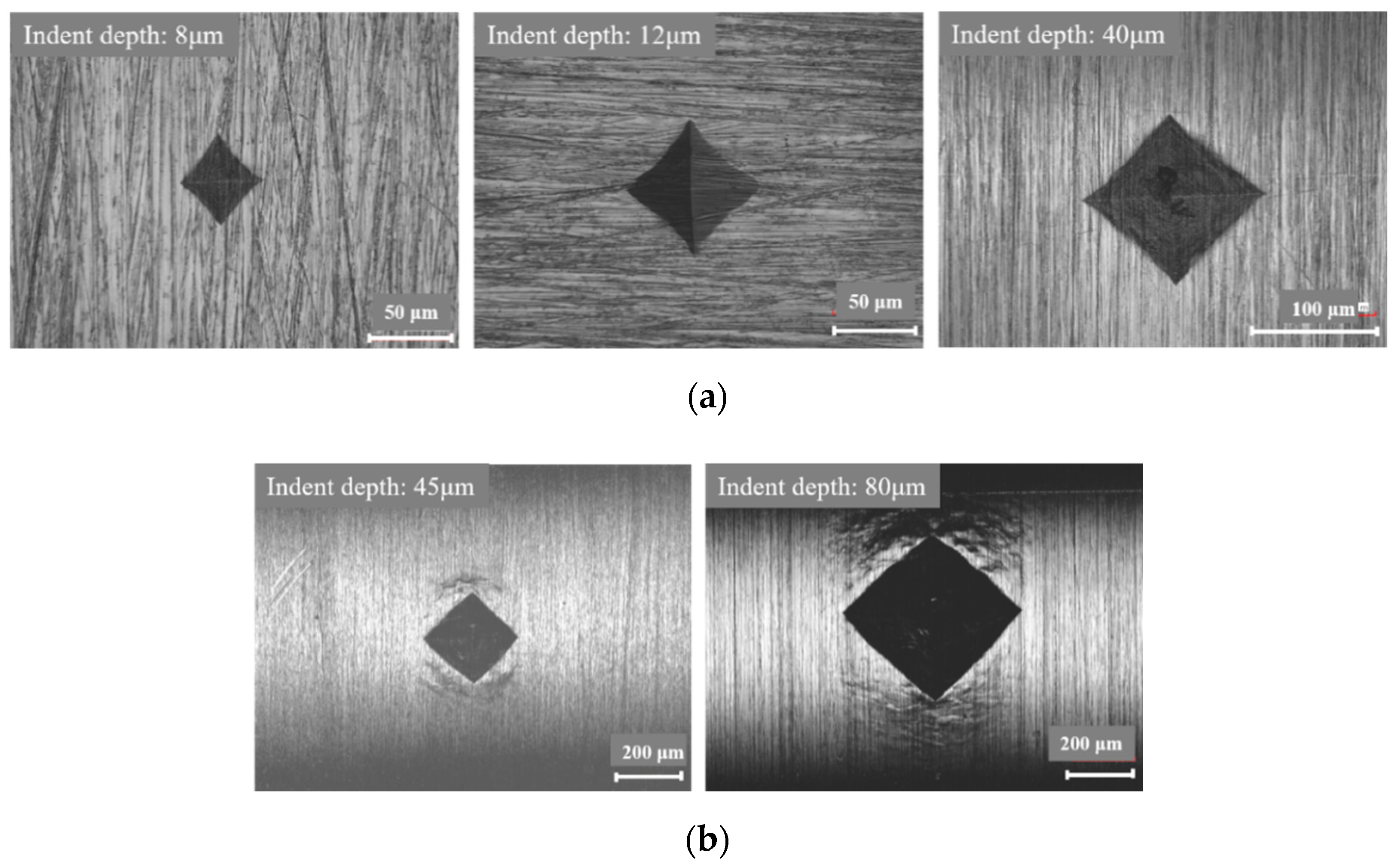
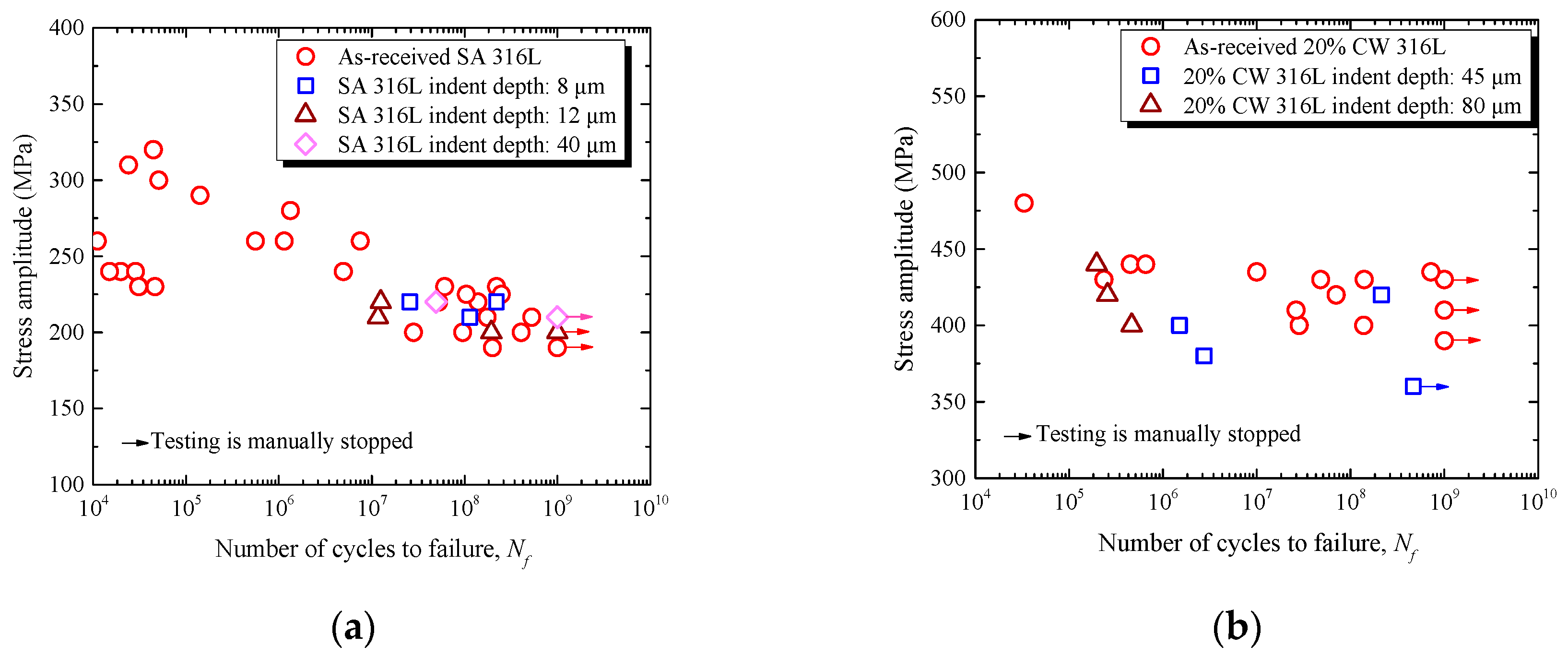
In the case of SA 316L, the fatigue crack initiation was not affected by an indent with a depth of 40 μm, i.e., the VHCF strength was not affected when the indent depth was less than 40 μm. The critical value of the indent depth was consistent with the results obtained from the empirical formula.
(3)
In the case of 20% CW 316L, the fatigue crack initiation was not affected by an indent with a depth of 80 μm, i.e., the VHCF strength was not affected when the indent depth was less than 80 μm. The critical value of the indent depth was much larger than that obtained from the empirical formula, which might have been caused by the enhanced fatigue strength induced by the plastic deformation, residual stress, and probable deformation-induced martensite transition around the indent.

Author Contributions

Z.X. carried out the experimental works, analysis, and writing under the supervision of T.N. and M.F.

Funding

This research was funded the Fundamental Research Funds for the Central Universities, grant number 17lgpy34, and the Natural science foundation of the Guangdong province, grant number 2018A030310102. This work was also supported by JSPS KAKENHI Grant Numbers JP26820016, JP17K14565.

Conflicts of Interest

The authors declare no conflict of interest.

References

  1. Chai, M.Y.; Li, L.C.; Bai, W.J.; Duan, Q. Investigation on Acoustic Emission Characteristics from Corrosion of Conventional Materials of Primary Pipe in Nuclear Power Plants. Appl. Mech. Mater. 2014, 487, 54–57. [Google Scholar] [CrossRef]
  2. Naoe, T.; Xiong, Z.; Futakawa, M. Gigacycle fatigue behaviour of austenitic stainless steels used for mercury target vessels. J. Nucl. Mater. 2015, 468, 331–338. [Google Scholar] [CrossRef]
  3. Li, S.X. Effects of inclusions on very high cycle fatigue properties of high strength steels. Int. Mater. Rev. 2012, 57, 92–114. [Google Scholar] [CrossRef]
  4. Hong, Y.; Sun, C. The nature and the mechanism of crack initiation and early growth for very-high-cycle fatigue of metallic materials-An overview. Theor. Appl. Fract. Mech. 2017, 92, 331–350. [Google Scholar] [CrossRef]
  5. Hong, Y.; Liu, X.; Lei, Z.; Sun, C. The formation mechanism of characteristic region at crack initiation for very-high-cycle fatigue of high-strength steels. Int. J. Fatigue 2016, 89, 108–118. [Google Scholar] [CrossRef] [Green Version]
  6. Carstensen, J.; Mayer, H.; Brøndsted, P. Very high cycle regime fatigue of thin walled tubes made from austenitic stainless steel. Fatigue Fract. Eng. Mater. 2002, 25, 837–844. [Google Scholar] [CrossRef]
  7. Takahashi, K.; Ogawa, T. Evaluation of giga-cycle fatigue properties of austenitic stainless steels using ultrasonic fatigue test. J. Solid Mech. Mater. Eng. 2008, 2, 366–373. [Google Scholar] [CrossRef]
  8. Xiong, Z.H.; Futakawa, M.; Naoe, T.; Maekawa, K. Very High Cycle Fatigue in Pulsed High Power Spallation Neutron Source. Adv. Mater. Res. 2014, 891–892, 536–541. [Google Scholar] [CrossRef]
  9. Naoe, T.; Xiong, Z.; Futakawa, M. Temperature measurement for in-situ crack monitoring under high-frequency loading. J. Nucl. Mater. 2018, 506, 12–18. [Google Scholar]
  10. Mughrabi, H. Specific features and mechanisms of fatigue in the ultrahigh-cycle regime. Int. J. Fatigue 2006, 28, 1501–1508. [Google Scholar]
  11. Bathias, C.; Wang, C. Initiation from Low Cycle Fatigue to Gigacycle Fatigue. Adv. Mater. Res. 2014, 891–892, 1419–1423. [Google Scholar] [CrossRef]
  12. Kalainathan, S.; Sathyajith, S.; Swaroop, S. Effect of laser shot peening without coating on the surface properties and corrosion behavior of 316L steel. Opt. Laser Eng. 2012, 50, 1740–1745. [Google Scholar] [CrossRef]
  13. Futakawa, M.; Naoe, T.; Tsai, C.; Kogawa, H.; Ishikura, S.; Ikeda, Y.; Soyama, H.; Date, H. Pitting damage by pressure waves in a mercury target. J. Nucl. Mater. 2005, 343, 70–80. [Google Scholar] [CrossRef]
  14. Futakawa, M.; Naoe, T.; Kogawa, H.; Teshigawara, M.; Ikeda, Y. Effects of pitting damage on fatigue limit and lifetime in mercury target. J. Nucl. Mater. 2006, 356, 168–177. [Google Scholar] [CrossRef]
  15. Man, J.; Smaga, M.; Kuběna, I.; Eifler, D.; Polák, J. Effect of metallurgical variables on the austenite stability in fatigued AISI 304 type steels. Eng. Fract. Mech. 2017, 185, 139–159. [Google Scholar] [CrossRef]
  16. Basu, K.; Das, M.; Bhattacharjee, D.; Chakraborti, P.C. Effect of grain size on austenite stability and room temperature low cycle fatigue behaviour of solution annealed AISI 316LN austenitic stainless steel. Met. Sci. J. 2013, 23, 1278–1284. [Google Scholar] [CrossRef]
  17. Gussev, M.N.; Busby, J.T.; Byun, T.S.; Parish, C.M. Twinning and martensitic transformations in nickel-enriched 304 austenitic steel during tensile and indentation deformations. Mater. Sci. Eng. A Struct. Mater. Prop. Microstruct. Process. 2013, 588, 299–307. [Google Scholar] [CrossRef]
  18. Smaga, M.; Boemke, A.; Daniel, T.; Klein, M.W. Metastability and fatigue behavior of austenitic stainless steels. In MATEC Web of Conferences; EDP Sciences: Les Ulis, France, 2018; p. 04010. [Google Scholar]
  19. Varma, S.; Kalyanam, J.; Murk, L.; Srinivas, V. Effect of grain size on deformation-induced martensite formation in 304 and 316 stainless steels during room temperature tensile testing. J. Mater. Sci. Lett. 1994, 13, 107–111. [Google Scholar] [CrossRef]
  20. Grigorescu, A.C.; Hilgendorff, P.M.; Zimmermann, M.; Fritzen, C.P.; Christ, H.J. Cyclic deformation behavior of austenitic Cr-Ni-steels in the VHCF regime: Part I-Experimental study. Int. J. Fatigue 2016, 93, 250–260. [Google Scholar] [CrossRef]
  21. Pokor, C.; Brechet, Y.; Dubuisson, P.; Massoud, J.-P.; Averty, X. Irradiation damage in 304 and 316 stainless steels: Experimental investigation and modeling. Part II: Irradiation induced hardening. J. Nucl. Mater. 2004, 326, 30–37. [Google Scholar] [CrossRef]
  22. Strizak, J.; Tian, H.; Liaw, P.; Mansur, L. Fatigue properties of type 316LN stainless steel in air and mercury. J. Nucl. Mater. 2005, 343, 134–144. [Google Scholar] [CrossRef]
  23. Ranc, N.; Wagner, D.; Paris, P.C. Study of thermal effects associated with crack propagation during very high cycle fatigue tests. Acta Mater. 2008, 56, 4012–4021. [Google Scholar] [CrossRef] [Green Version]
  24. Stanzl-Tschegg, S. Very high cycle fatigue measuring techniques. Int. J. Fatigue 2014, 60, 2–17. [Google Scholar] [CrossRef]
  25. Maeng, W.Y.; Kim, M.H. Comparative study on the fatigue crack growth behavior of 316L and 316LN stainless steels: Effect of microstructure of cyclic plastic strain zone at crack tip. J. Nucl. Mater. 2000, 282, 32–39. [Google Scholar] [CrossRef]
  26. Mughrabi, H. On the life-controlling microstructural fatigue mechanisms in ductile metals and alloys in the gigacycle regime. Fatigue Fract. Eng. Mater. 1999, 22, 633–641. [Google Scholar] [CrossRef]
  27. Murakami, Y. Metal Fatigue: Effects of Small Defects and Nonmetallic Inclusions; Elsevier: Oxford, UK, 2002. [Google Scholar]
  28. Siebel, E. Influence of surface roughness on the fatigue strength of steels and non-ferrous alloys. Eng. Dig. 1957, 18, 109–112. [Google Scholar]
  29. Itoga, H.; Tokaji, K.; Nakajima, M.; Ko, H.N. Effect of surface roughness on step-wise-characteristics in high strength steel. Int. J. Fatigue 2003, 25, 379–385. [Google Scholar] [CrossRef]
  30. Xin, L.S. Very High Cycle Fatigue Properties of High Strength Steels: Effects of Nonmetallic Inclusions; Metallurgical Industry Press: BeiJing, China, 2010. [Google Scholar]
  31. Cheng, X.; Fisher, J.W.; Prask, H.J.; Gnäupel-Herold, T.; Yen, B.T.; Roy, S. Residual stress modification by post-weld treatment and its beneficial effect on fatigue strength of welded structures. Int. J. Fatigue 2003, 25, 1259–1269. [Google Scholar] [CrossRef]
Figure 1. A schematic drawing of the ultrasonic fatigue specimen (dimensions in mm).
Metals 09 00412 g001
Figure 2. LSM images of indents on the specimen surface of (a) SA 316L and (b) 20% CW 316L.
Metals 09 00412 g002
Figure 3. A photograph of the ultrasonic fatigue test setup.
Metals 09 00412 g003
Figure 4. (a) The S-N curves of SA 316 with and without indents. (b) The S-N curves of 20% CW 316 with and without indents.
Metals 09 00412 g004
Figure 5. Images of the indents before and after the fatigue test. The crack did not originate from the indent. (a) Tested at 220 MPa and failed at 2.57 × 10⁷ cycles; (b) tested at 220 MPa and failed at 1.25 × 10⁷ cycles.
Metals 09 00412 g005
Figure 6. Images of the fatigue cracks on the specimen surface of 20% CW 316L with indents. (a) Tested at 380 MPa failed at 2.75 × 10⁶ cycles with an indent depth of 45 μm; (b) tested at 400 MPa and failed at 4.65 × 10⁵ cycles with an indent depth of 80 μm.
Metals 09 00412 g006aMetals 09 00412 g006b
Figure 7. The temperature distribution of the specimen surface obtained by thermography in a 20% CW 316L specimen (indent depth is 45 μm) tested at 380 MPa, which failed at 2.75 × 10⁶ cycles. (a) Before fatigue test; (b) just before fatigue failure. Note: ∆T is defined as the specimen temperature changes with respect to minimum temperature at the initial state, as well as in Figure 8.
Metals 09 00412 g007
Figure 8. The temperature distribution of the specimen surface obtained by thermography in a 20% CW 316L specimen (indent depth is 80 μm) tested at 400 MPa, which failed at 4.65 × 10⁵ cycles. (a) Before fatigue test; (b) just before fatigue failure.
Metals 09 00412 g008
Figure 9. Dependence of the crack propagation life (Ni) over the fatigue life (Nf) on the number of cycles to failure of SA and 20% CW 316L.
Metals 09 00412 g009
Figure 10. A schematic view of the indent area.
Metals 09 00412 g010

