Article

Influence of Mechanical Anisotropy on Micro-Voids and Ductile Fracture Onset and Evolution in High-Strength Low Alloyed Steels

1
Rina Consulting—Centro Sviluppo Materiali S.p.A, Via di Castel Romano 100, 00128 Roma, Italy
2
Department of Mechanical and Aerospace Engineering, Sapienza University of Rome, via Eudossiana 18, 00184 Roma, Italy
3
Dipartimento di Ingegneria, Università di Perugia, 06125 Perugia, Italy
*
Author to whom correspondence should be addressed.
Metals 2019, 9(2), 224; https://doi.org/10.3390/met9020224
Submission received: 20 December 2018 / Revised: 4 February 2019 / Accepted: 12 February 2019 / Published: 13 February 2019
(This article belongs to the Special Issue High-Strength Low-Alloy Steels)

Abstract

:
In this paper results of a wide and innovative mechanical assessment, that was performed on large diameter spiral line pipes for gas transportation, are reported. The anisotropic material hardening has been characterized by tensile (smooth and notched specimens), torsion, and compression tests. Tests were performed in the pipe of the pipe with specimens machined along several orientations, taking into account the pipe through thickness direction. The influence of different triaxiality stress states on anisotropic behavior of the material have also been analyzed by means of tensile tests on notched specimens. After the experiments, the material was assessed by measuring the void distribution on the material as is, and on many deformed and fractured specimens, including tensile tests at different triaxiality, and torsion tests. The results showed that in such a class of materials, the experimental void fraction is fully negligible and not related to the applied plastic strain, even at the fracture proximity. As a consequence it can be concluded that, the plastic softening hypothesis may be dropped and damage due to void evolution hypothesis is not adequate.

1. Introduction

Oil and gas transmission pipeline steel, with high deformation capability, is required if environments, involving large strata movement, are considered. In fact, in such cases, the pipe is subjected to large plastic deformations, that could finally cause the pipeline failure. Pipelines that are used in such environments are designed according to the following strain-based approach, in order to prevent failure. This strain-based design strategy for transmission pipelines requires the capability to face high internal operating pressure and high deformation resistance. As a consequence, pipeline steel, designed for strain-based applications, will target high strength/toughness, good welding performance, and excellent plastic deformation capability. This implies that the pipeline steel transverse properties will meet the pipeline steel grade requiring technical specification in terms of strength, toughness, drop weight tear test, and hardness.
In addition to the transverse mechanical characteristic requirements, pipelines designed for such applications are also required to meet longitudinal targets. A higher degree of deformation-enhanced index (n), larger uniform elongation (Ag), low yield stress to tensile strength ratio (Rt0.5/Rm), continuous yielding (roundhouse) tensile stress-strain curve, with no yield point elongation, are needed to target an appropriate longitudinal deformation ability. The development of high-strength line pipes, aimed to target strain-based applications, has been carried out in recent years [1,2,3,4]. In this framework, the design and prediction methods have continuously improved [5]. Considering the plate material development, it is known that a proper design and control of micro-structure are key to success. Steel chemical composition and cooling processes are the most significant parameters affecting the plate micro-structure [6,7,8,9,10,11]. Also, small differences in cooling rates can strongly modify mechanical properties, such as uniform elongation and Rt0.5/Rm [10].
Tensile properties of line pipes are strongly dependent on different positions along the pipe principal axes [12,13]. Anisotropic or orthotropic material properties strongly effect the pipeline performances, and large straining beyond the plastic instability limit (necking) needs to be properly described, taking into account of anisotropic plasticity constitutive law, aimed at capturing the material ductile behavior.
The scope of this paper is to describe a wide and innovative mechanical assessment, performed on large diameter spiral line pipes for gas transportation. The aim of such work is to validate a new plasticity model, developed at Rina Consulting–Centro Sviluppo Materiali [14,15,16]. Subsequent to mechanical tests, fracture surfaces and the section of selected specimens, were analyzed for voids- and inclusions-counting. Void counting was carried out on virgin material, and on areas next to the fracture surface, where the material reach elevated strain values. The results show that, in the considered material, the void fraction is fully negligible. Moreover, it is not related to the plastic strain applied, even at the fracture proximity. This result confirms those obtained in previous work on other materials [17], and the consequence is that, for such class of materials, the matrix softening hypothesis may be abandoned in the plastic behavior, and that damage evolution is not related do void nucleation and growth.
The Rina-CSM model is based on “Hill (48)” criterion, it provides a 3-D description of the anisotropic behavior to represent the ductile hardening in all the principal directions of the material. Moreover, the Lode angle effect is also introduced in the model, which allows a sound description of the effect of shear stress states. Such a model makes use of a series of coefficients which have a physical meaning, and that can be obtained by tensile and torsion testing, conducted in conventional mechanical laboratories.
The scope of this work is to measure differences in terms of initial yield stress and subsequent hardening of the material for different orientations under tensile, shear, and compressive stress states. The results should provide a useful complete characterization of the investigated materials, and will be used in a future work, to calibrate and implement the above-mentioned numerical model in a commercial finite element software.

2. Materials and Methods

The main information of the pipe used for specimen extraction is reported in Table 1.
The chemical composition of the studied material is reported in Table 2.
Material anisotropy has been assessed in terms of tensile and torsion tests performed in the base material. Tensile specimen were machined considering six different orientations. Each type of test was carried out on two specimen, in order to check the repeatability of the results. Three standard tensile tests, with geometry according to UNI EN ISO 6892-1:2009, are carried out on round bar, smooth specimens having 9 mm gauge section diameter, machined starting from the longitudinal (L), transversal (T), and at 45° degrees between L-T directions (45° LT) of the pipe. Three tensile tests are carried out on round specimens, having 2.5 mm gauge section diameter, extracted in the through thickness direction of the pipe (N), and oriented at 45° degrees from the longitudinal and through the thickness direction (45° LN), and at 45° degrees from the transversal and through the thickness direction (45° TN), (Figure 1).
Tensile specimen sizes are limited by the pipe wall thickness. To obtain experimental tensile stress strain curve from these specimens, the strain during the test was measured by a general purpose extensometer, with initial gauge length of 4 mm.
Additional tests are carried out on conventional round bar smooth specimens having 9 mm gauge section diameter, machined in the longitudinal (LC), transversal (TC) and 45° degrees between L-T directions (45° LTC) of the coil original rolling direction, (Figure 2).
Torsion tests were also performed in the longitudinal (L), and transversal direction (T), on round bar specimens having a gauge diameter of 8 mm and a gauge length of 17 mm (Figure 3).
Custom tension-torsion equipment was used, that is capable of maximum axial and torsional loads of 100kN and 1000 Nm axial stroke up to 150 mm and unlimited rotation angle. Torque and rotation are measured by means of a bi-axial load cell and a digital encoder, embedded in the rotational actuator. The machine torsional stiffness is granted by a four-columns frame and by a bulky design of the grips. All tests have been executed in a free-end configuration (null axial load) to ensure a pure shear state of stress.
Further tensile tests are carried out on specimens with notched geometry (Figure 4), with two different notch radii of 10 and 2 mm. The specimens are extracted in the longitudinal (L), and transversal (T) of the pipe. The aim of these tension test is to assess the material anisotropic behavior under different stress states induced by the different notch radii [18].
In order to better assess the material behavior in the pipe through thickness direction (N), two compressive tests were performed on cylindrical specimen. As for the tensile specimens, the compression specimen size is limited by the pipe wall thickness. For current tests, a 12 mm height, with 6 mm diameter cylindrical geometry, was used.
After the execution of the mechanical tests, the fracture surfaces were analyzed by Scanning Electron Microscope Field Emission Gun (SEM FEG) LEO 1550 (Zeiss, Oberkochen, Germany) Selected specimens were sectioned and analyzed for voids and inclusions. Considered areas for such measure was far from fractured surface to assess the void fraction on as is material Next void counting was extended to areas taken along the longitudinal specimen axis, starting from the fractured surface (Figure 5).

3. Results

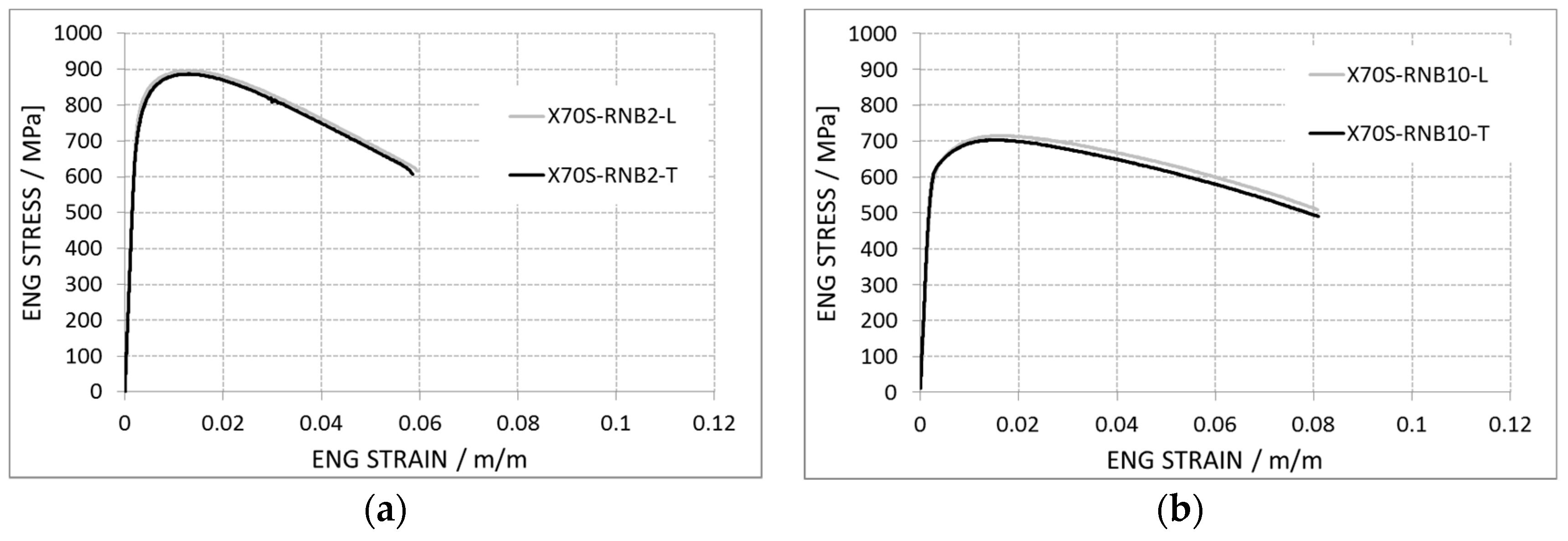
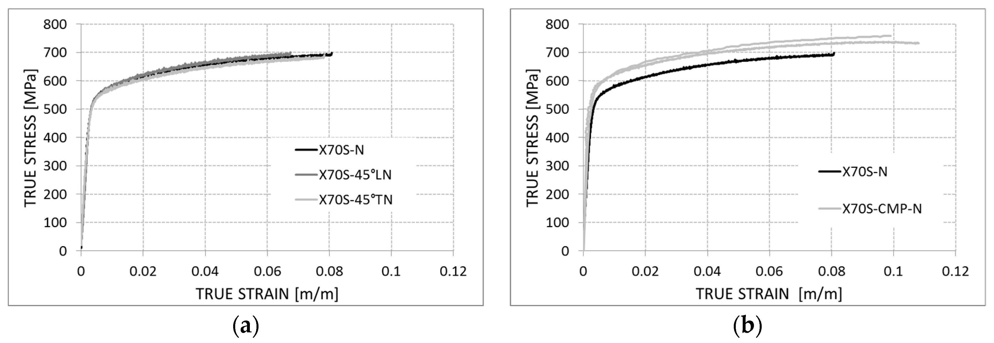
3.1. Experimental Tests Results

The results of the tensile tests on the round bar specimens, are shown in terms of true stress-strain curves for the strain, up to specimen necking. Standard tensile tests, performed on plane pipe directions, are reported in the subsequent Figure 6.
Considering a spiral pipe forming angle of about 25°, for the spiral pipe, 6 different orientations for the in plane tensile test are considered (Table 3).
The yield stress at different orientation are reported in Figure 7 below.
The tensile tests carried out on notched specimen are reported in terms of the engineering stress strain curve (Figure 8). The two specimen geometries have different values of notch radius and minimum diameter of the cross section (i.e., 5 mm diameter for notch radius = 10 mm and 6 mm diameter for notch radius = 2 mm) and this induces a different stress state (i.e., triaxiality) during the tests. The material shows very similar behavior in the longitudinal (L) and transverse (T) direction for the RNB10 specimens and identical behavior for the RNB2.
The results, obtained from tensile tests on mini round specimens, are summarized in Figure 9a. Specimens are extracted in the through thickness direction of the pipe (N), and oriented at 45° degrees from longitudinal, and through thickness direction (45° LN) and at 45° degrees from transversal, and through thickness direction (45° TN). In order to analyze a possible strength differential effect in the through thickness direction of the material, the tensile curves are compared with the compression curves in the Figure 9b.
True stress-strain curves of the material, for the in-plane pipe directions, can also be derived from torsion tests. True stress-strain curves are obtained by means of torsion tests up to large strain, exclusively from the elaboration of experimental data. This can be accomplished by relying on the equilibrium relations, or equivalently using the well-known Nadai’s formula [19], which gives the material shear stress- shear strain (τ−γ) curve, starting from the raw torque-displacement (M-θ) results:
τ ( γ 0 ) = 1 2 π r 0 3 ( θ N d M d θ N + 3 M ) γ 0 = γ ( r 0 ) ,   θ N = d θ / d z
where r0 and γ0 are the outer radius and outer shear strain, and θn is the rotation per unit length. Then, using a standard J2 (von Mises) plasticity equivalence, an average stress-strain relation can be finally calculated:
σ = 3 τ σ = γ / 3
In the previous equation an isotropic equivalence is used instead of an anisotropic formulation. This is justified by the consideration that, the measured M-θ global quantities just reflect an average material behavior, as a consequence of each point of the specimen being subjected to loading in a different anisotropic direction.
Figure 10 shows the obtained results for both longitudinal and transversal tests.
In this case, material behavior seems only marginally affected by the test direction. This can be explained, considering that under torsion, the local state of stress is not directional. As a consequence, the overall response is somehow a mixture of the material behavior under all possible directions perpendicular to the specimen cut axis.

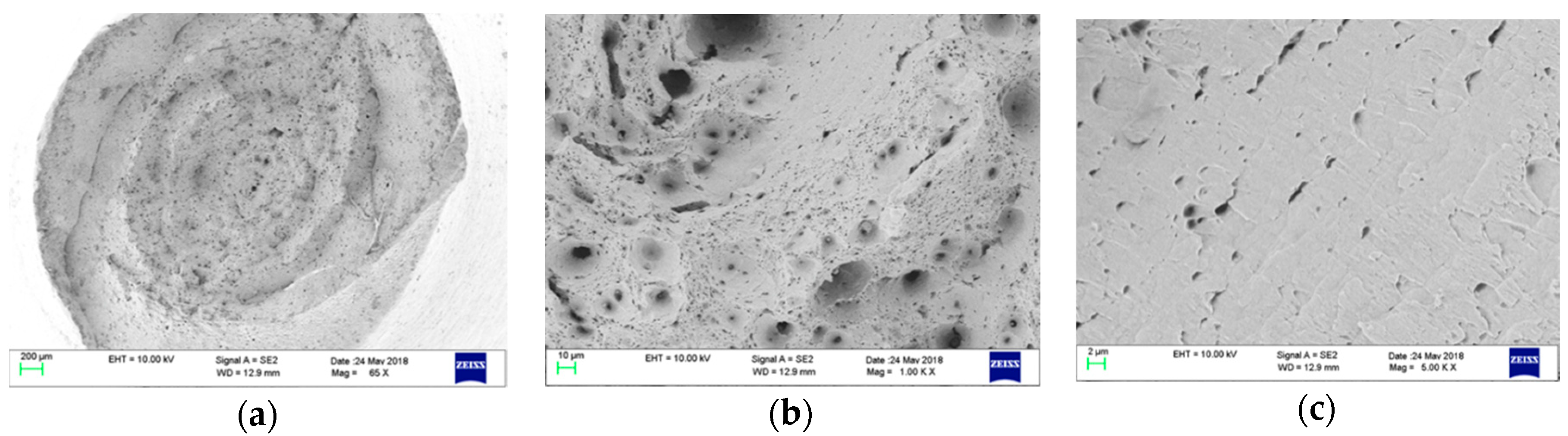
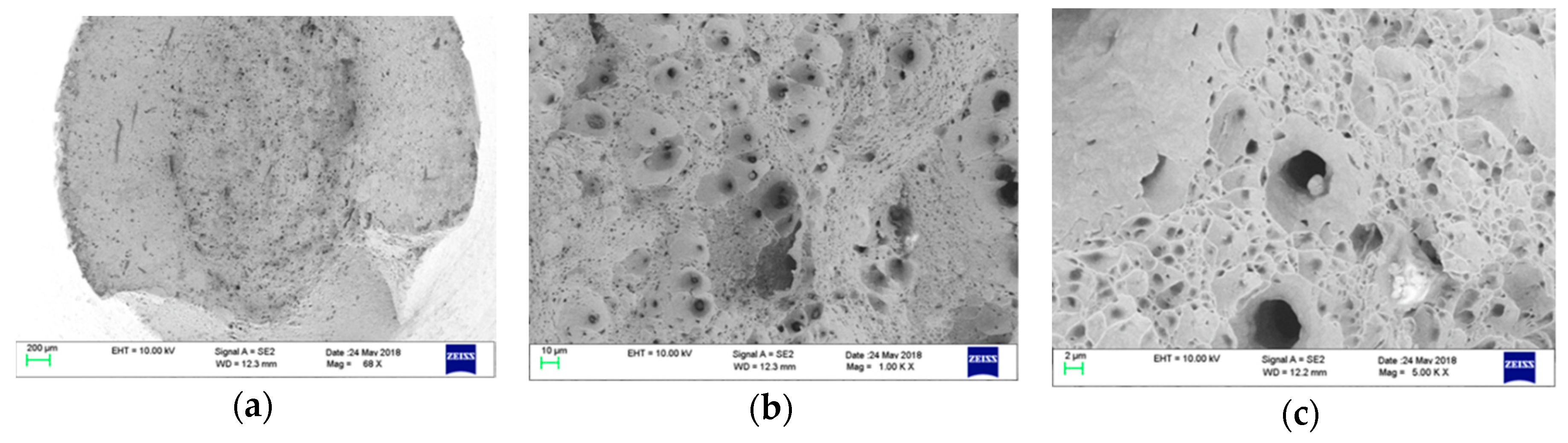
3.2. Fractographic Analysis Results

The X70 spiral pipe material has been assessed, measuring the void distribution on material as is, and on deformed and fractured tensile specimens, machined in the longitudinal (L), transversal (T) and 45° degrees, between L-T directions (45° LT) of the pipe. For every specimen, the SEM analysis of fractured surfaces, aimed at analyzing and measuring the dimple pattern, was performed (Figure 11, Figure 12 and Figure 13).

3.3. Material Voids Count

After the tests, the specimens were sectioned along a radial plane, to consider the longitudinal section. The void counting results are reported in the following Figure 14 and Figure 15.

4. Discussion

4.1. Mechanical Analysis

The manufacturing rolling process of the coil, and the following process of spiral pipe shaping, induce anisotropy in the final product. This is visible in analyzing the yield stress values of the material obtained from tensile tests, carried out on in-plane pipe directions (Figure 7). Spiral pipes show an anisotropic behavior, with the principal anisotropic axis rotated with a respect to both the pipe principal directions (i.e., longitudinal and circumferential) and coil principal directions.
For a better understanding of the material behavior differences in the three orientations, longitudinal, transversal, and radial, the stress-strain curves are reported in Figure 16. The first outcomes are that the differences in the stress strain curves evolve with the strain, such that the anisotropy of the pipes changes during deformation. The differences in material properties are found if the longitudinal and transverse directions are considered. It is worth noting that the thickness and material properties affect the pipe response to bi-axial stress state, like pipe-bending with internal pressure. Pipes with the same longitudinal and transversal material properties can show a different response to the same loading, due to the differences in material, through thickness behavior.
A comparison of the true stress strain curves, obtained from tensile and torsion tests, shows a substantial match in the behavior of the material when subjected to tensile or shear stress states.

4.2. Fractographic Analysis

Voids nucleation from defects, like inclusions and the subsequent coalescence, is one of the most accepted theories to describe the damaged mechanisms of the alloy steels during deformation. Many criteria have been proposed, based on void evolution theories [20,21] and porous models, like the popular Gurson model [22] are used to describe the softening of the materials.
From the results reported in the previous paragraph, the main outcomes can be summarized by the following bullet points:
From the SEM analysis of fracture surfaces:
  • No clear differences have been observed for the dimple geometries of the three tensile specimens oriented in different directions;
  • The geometry of the dimples on the fracture surfaces is almost circular, even though the cross sectional area of the specimens presented an elliptical geometry, due to the anisotropic behavior of the material.
From material voids count:
  • Voids fraction has an almost constant value (<0.5%) for the three specimens, also close to the fractured surfaces. Voids fractions are unrelated to the plastic strain reached from the material, and to the material orientation.
  • Damage evolution seems therefore not governed by microvoids evolution.

5. Conclusions

A thorough characterization of the anisotropic plastic behavior, and damage evolution of a structural steel for pipelines, was carried out successfully. The main results showed that yielding is affected by material direction, proving its anisotropic behavior, while the local behavior at fracture seems to be quite insensitive to anisotropy for the material under investigation. The dimples geometry, observed on fractured specimens, is similar for different orientations. This could justify a different approach to the problem of modelling the plastic deformation and damage of these alloy steels. The damage evolution could be regarded as uncoupled from the plastic behavior, and even if an anisotropic plasticity criterion is needed to correctly describe the material, the damage model could be even based on a simple isotropic formulation as a first attempt.

Author Contributions

Data curation, L.C.; Investigation, F.I. and A.D.S.; Methodology, F.I.; Supervision, T.C.; Validation, F.I.

Funding

This research received no external funding.

Conflicts of interest

Authors declare no conflict of interest.

References

  1. Liessem, A.; Rueter, P.; Pant, M.; Schwinn, V. Production and development update of x100 for strain-based design applications. J. Pipeline Eng. 2010, 9, 9–27. [Google Scholar]
  2. Hara, T.; Shinohara, Y.; Terada, Y.; Asahi, H.; Doi, H. Development of high-deformable high-strength line pipe suitable for strain-based design. In Proceedings of the 4th Pipeline Technology Conference, Hannover, Germany, 22–23 April 2009; pp. 154–160. [Google Scholar]
  3. Muraoka, R.; Kondo, J.; Ji, L.; Chen, H.; Feng, Y.; Ishikawa, N.; Okatsu, M.; Igi, S.; Suzuki, N.; Masamura, K. Production of grade x80 high strain linepipes for seismic region application. Proc. 8th Int. Pipeline Conf. 2010, 287–292. [Google Scholar] [CrossRef]
  4. Seo, D.-H.; Yoo, J.-Y.; Soon, W.-H.; Kang, K.-B.; Cho, W.-Y. Development of X80/X100 linepipe steel plates and pipes for strain based design pipeline. In Proceedings of the Nineteenth International Offshore and Polar Engineering, Osaka, Japan, 21–26 July 2009; pp. 61–66. [Google Scholar]
  5. Macia, M.L.; Kibey, S.A.; Arslan, H.; Bardi, F.; Ford, S.J.; Kan, W.C.; Cook, M.F.; Newbury, B. Approaches to qualify strain-based designed pipelines. In Proceedings of the 8th International Pipeline Conference, Calgary, AB, Canada, 27 September–1 October 2010; pp. 365–374. [Google Scholar]
  6. Suikkanen, P.; Karjalainen, L.; DeArdo, A. Effect of carbon content on the phase transformation characteristics, microstructure and properties of 500 mpa grade microalloyed steels with non-polygonal ferrite microstructures. La Metallurgia Italiana 2008, 6, 41–54. [Google Scholar]
  7. Regier, R.W.; Speer, R.W.; Matlock, D.K.; Choi, J.K. Effect of cooling rate on the crystallographic effective grain size of ferrite in low-carbon microalloyed steels. In Proceedings of the Association for Iron and Steel Technology International Symposium on the Recent Developments in Plate Steels, Winter Park, CO, USA, 19–22 June 2011; pp. 351–363. [Google Scholar]
  8. Di Schino, A.; Di Nunzio, P.E.; Turconi, G.L. Microstructure evolution during tempering of martensite in medium C steel. Mater. Sci. Forum 2007, 558–559, 1435–1441. [Google Scholar] [CrossRef]
  9. Di Nunzio, P.; Di Schino, A. Effect of Nb microalloying on the heat affected zone microstructure of girth welded joints. Mater. Lett. 2017, 186, 86–89. [Google Scholar]
  10. Rufini, R.; Di Pietro, O.; Di Schino, A. Predictive simulation of plastic processing of welded stainless steel pipes. Metals 2018, 8, 519. [Google Scholar] [CrossRef]
  11. Corradi, M.; Di Schino, A.; Borri, A.; Rufini, R. A review of the use of stainless steel for masonry repair and reinforcement. Constr. Build. Mater. 2018, 181, 335–346. [Google Scholar] [CrossRef]
  12. Sun, H.; An, S.; Meng, D.; Xia, D.; Kang, Y. Influence of cooling condition on microstructure and tensile properties of x80 high deformability line pipe steel. In Proceedings of the 10th International Conference on Steel Rolling, Beijing, China, 15–18 September 2010; pp. 420–426. [Google Scholar]
  13. Tanguy, B.; Luu, T.T.; Perrin, G.; Pineau, A.; Besson, J. Plastic and damage behaviour of a high strength X100 pipeline steel: Experiments and modelling. Int. J. Pres. Ves. Pip. 2008, 85, 322–335. [Google Scholar] [CrossRef]
  14. Iob, F.; Campanelli, F.; Coppola, T. Modelling of anisotropic hardening behavior for the fracture prediction in high strength steel line pipes. Eng. Fract. Mech. 2018, 148, 363–382. [Google Scholar] [CrossRef]
  15. Research Programme of the Research Fund for Coal and Steel, Contract N. RFSR-CT-2011-00029, project acronym ULCF. Available online: http://ec.europa.eu/research/participants/data/ref/other_eu_prog/rfcs/rfcs-call-summaries_en.pdf (accessed on 20 December 2018).
  16. Research Programme of the Research Fund for Coal and Steel, Contract N. RFSR-CT-2013-00025, project acronym SBD-SPipe. Available online: https://ec.europa.eu/research/industrial_technologies/pdf/rfcs/summaries-rfcs_en.pdf (accessed on 20 December 2018).
  17. Coppola, T.; Iob, F.; Campanelli, F. Critical review of ductile fracture criteria for steels. In Proceedings of the 20th European Conference on on Fracture (ECF20) Steel Rolling, Trondheim, Norway, 30 June–4 July 2014. [Google Scholar]
  18. Coppola, T.; Demofonti, G.; Mannucci, G. Numerical-experimental procedures to identify the ductile fracture strain limits in pipeline steels. In Proceedings of the 19th International Offshore and Polar Engineering Conference, Osaka, Japan, 21–26 July 2009. [Google Scholar]
  19. Nadai, A. Theory of flow and fracture of solids, 2nd ed.; McGraw-Hill: New York, NY, USA, 1950. [Google Scholar]
  20. McClintock, F.A. A criterion for ductile fracture by growth of holes. J. Appl. Mech. 1968, 35, 363–371. [Google Scholar] [CrossRef]
  21. Rice, J.R.; Tracey, D.M. On the ductile enlargement of voids in triaxial stress fields. J. Mech. Phys. Solids 1969, 17, 201–217. [Google Scholar] [CrossRef]
  22. Gurson, A.L. Continuum theory of ductile rupture by void nucleation and growth. Part I. Yield criteria and flow rules for porous ductile media. J. Eng. Mater. Technol. 1977, 99, 2–15. [Google Scholar] [CrossRef]
Figure 1. Mini round tensile specimen (mm) (N = normal; L = longitudinal).
Metals 09 00224 g001
Figure 2. Principal orientations for in plane mechanical test.
Metals 09 00224 g002
Figure 3. Torsion specimen (mm).
Metals 09 00224 g003
Figure 4. Round notched tensile specimen (mm): (a) Notch radius = 10 mm; (b) Notch radius = 2 mm.
Metals 09 00224 g004
Figure 5. Void counting procedure.
Metals 09 00224 g005
Figure 6. True stress-strain curves from tensile tests on X70 48” Outer Diameter (OD) spiral Pipe: (a) Tests according to Pipe directions; (b) Tests according to Coil directions.
Metals 09 00224 g006
Figure 7. Yield stress derived from tensile tests on X70 48” OD Spiral Pipe for different orientation. (Longitudinal pipe direction = 0°).
Metals 09 00224 g007
Figure 8. Engineering stress-strain curves derived from notched tensile tests on X70 48” OD Spiral Pipe: (a) Notch radius = 2 mm; (b) Notch radius = 10 mm.
Metals 09 00224 g008
Figure 9. True stress-strain curves derived from tensile and compression tests on X70 48” OD Spiral Pipe: (a) 2,5 mm OD round bar test; (b) 6 mm OD compression test.
Metals 09 00224 g009
Figure 10. True stress-strain curves derived from torsion tests on X70 48” OD Spiral Pipe.
Metals 09 00224 g010
Figure 11. SEM Analysis of X70 Transversal pipe tensile specimen: (a) Mag 63 X; (b) Mag 1000 X; (c) Mag 5000 X.
Metals 09 00224 g011
Figure 12. SEM Analysis of X70 Longitudinal pipe tensile specimen: (a) Mag 63 X; (b) Mag 1000 X; (c) Mag 5000 X.
Metals 09 00224 g012
Figure 13. SEM Analysis of X70 45° LT pipe tensile specimen: (a) Mag 63 X; (b) Mag 1000 X; (c) Mag 5000 X.
Metals 09 00224 g013
Figure 14. Void counting performed on tensile specimens after the test: (a) Transversal pipe tensile specimen; (b) Longitudinal pipe tensile specimen; (c) 45° LT pipe tensile specimen.
Metals 09 00224 g014
Figure 15. Void counting performed on torsion specimens after the test: (a) Transversal pipe tensile specimen; (b) Longitudinal pipe tensile specimen.
Metals 09 00224 g015
Figure 16. X70 true stress-strain curves derived from tensile tests on 48” OD Spiral Pipe: (a) Standard view; (b) Magnified view.
Metals 09 00224 g016
Table 1. Investigated material.
Material GradePipe Outer Diameter/mmPipe Wall Thickness/mmPipe Manufacturing Process
API X70121919.3Spiral
Table 2. Material chemical composition.
Max, %
CMnSiPSVNbTi
0.161.70.450.0250.0200.100.060.006
Table 3. Orientation for tensile tests on X70 48” OD Spiral Pipe.
Orientation IDOrientation Direction
Longitudinal Pipe0 and 180
Transversal Coil25 and 205
45° LT Coil70 and 250
Transversal Pipe90 and 270
Longitudinal Coil115 and 295
45° LT Pipe135 and 315

