Article

Varestraint Testing of Selective Laser Additive Manufactured Alloy 718—Influence of Grain Orientation

Department of Engineering Science, University West, 461 32 Trollhättan, Sweden
*
Author to whom correspondence should be addressed.
Metals 2019, 9(10), 1113; https://doi.org/10.3390/met9101113
Submission received: 6 September 2019 / Revised: 9 October 2019 / Accepted: 16 October 2019 / Published: 18 October 2019
(This article belongs to the Special Issue Welding Metallurgy and Weldability of Superalloys)

Abstract

:
The effect of grain orientation on hot cracking susceptibility of selective laser additive manufactured Alloy 718 was investigated by Varestraint testing. Electron backscattered diffraction showed that cracks in heat affected zone (HAZ) of the welded samples occurred in high angle grain boundaries. The extent of HAZ cracking was smaller in samples tested parallel to the elongated grain orientation and larger in samples transverse to the elongated grain orientation. However, for solidification cracking in the weld metal, no significant difference with respect to grain orientation in the base metal was found.

1. Introduction

During the past decade, significant attention has been drawn to additive manufacturing (AM), which is a unique manufacturing process that allows for parts of various complexity to be built layer-by-layer [1]. Selective Laser Melting (SLM) is a conventional Laser-Powder Bed Fusion (L-PBF) process that involves melting of a thin layer of metallic powder on a substrate plate and then moving a focused laser in a specified pattern along the powder bed. The laser irradiated powder melts forming a micro-sized melt pool. The melt pool rapidly solidifies upon the removal of the laser and individual tracks of solid material forms. The sum of individual tracks within a plane forms a layer. A layer of powder is again applied on the solidified layer and the laser scans the powder to build the next layer. The process is repeated until the part is completed.
Some limitations with the SLM technology are the low rate of production and the limited part size due to the size of building chamber [1]. In order to evade these limitations, parts can be joined by welding technologies such as gas tungsten arc welding and laser beam welding. In this way, SLM manufactured parts can be joined with other SLM parts as well as with conventionally manufactured semi-finished products (i.e. cast and wrought material forms).
In this work, SLM manufactured Alloy 718 is investigated. Alloy 718 is the most widely used iron-nickel based superalloy in aero engines. It is a precipitation hardening superalloy that is commonly used in cast and wrought forms in manufacturing of hot structural components of gas turbine engines. This alloy has a Nb content of ~5 wt.% and is strengthened mainly by γ″ (Ni3Nb) and slightly by γ′ (Ni3(Al, Ti)) phases [2]. Interdendritic segregation of Nb is very common in conventionally cast [2], welded [2], and L-PBF manufactured Alloy 718 [3,4], which in turn result in the formation of the brittle Laves phase [(Ni, Fe, Cr)2(Nb, Mo, Ti)]. Other phases occurring in the alloy include δ-phase (Ni3Nb), and various metal carbides and nitrides, such as NbC, TiC, Cr23C6 and TiN.
The weldability of Alloy 718 has been extensively studied since the alloy was developed. The main problem when welding this alloy is the hot cracking sensitivity. Many approaches have been used to determine the hot cracking sensitivity of Alloy 718, one of them is Variable-Restraint (Varestraint) weldability test. Varestraint testing is a method of determining susceptibility to solidification and liquation cracking of the materials. The Varestraint test uses a controlled, externally applied bending strain to produce cracking during actual welding of the alloy. By varying the amount of strain, a threshold strain, i.e. the strain at which cracks start to form and a saturation strain, i.e. the strain at which crack length do not increase any further can be determined. After testing, the total and maximum crack lengths can be measured, usually on the upper surface of the specimen. These crack lengths, and the threshold and saturation strains are essential in determining the weldability of an alloy [5]. The sensitivity to hot cracking in the alloy can be aggravated due to constitutional liquation of carbides, liquation of Laves phase, or the segregation of trace elements like B, P, C or S in the grain boundaries [6,7,8,9]. Grain boundary segregation of these trace elements influences the formation and stability of the intergranular liquid that may form during the welding cycle by reducing the melting point of the grain boundary [6].
However, there are no or just a very limited amount of research publications that have investigated the influence of grain orientation on the susceptibility of hot cracking in Alloy 718. Investigations regarding the influence of grain orientation with regard to hot cracking susceptibility have been carried out in other types of alloys. Lippold et al. [10] studied liquation cracking in the partial melted zone (PMZ) of 5083 aluminum alloy plates and found that PMZ cracking was more severe in welds made transverse to the rolling direction in those made parallel to the rolling direction. The authors suggested that in the latter case the elongated grains produced by the rolling process were parallel to the weld, hence, it was more difficult for cracks to propagate into the base metal. Sidhu et al. [11] investigated the HAZ cracking susceptibility in directionally solidified (DS) IN738 alloy, laser welded in longitudinal and transverse directions (with regard to grain orientation). In this way they intersected different numbers of grain boundaries while welding. Their results showed a decrease in HAZ cracking with the reduction in number of high angle grain boundaries that intersected the weld bead. It is known from the literature that the grain boundary energy is inherently high for high angle grain boundaries and impurity atoms often preferentially segregate along these boundaries because of their higher energy state. Guo et al. [12] studied, by Gleeble testing, the correlation between grain boundary characteristics and intergranular liquation in Alloy 718 and reported that liquation mostly occurred at high angle grain boundaries when compared to low angle or special boundaries such as twin boundaries. An issue regarding the SLM manufactured parts, which has been widely investigated by researchers over the past few years, is the relationship between the sample building direction and grain orientation to tensile properties of SLM manufactured parts. Research regarding the influence of building direction on mechanical properties of Alloy 718 disclosed that the strength perpendicular to the building direction was generally higher than parallel to the building direction, while the ductility showed the opposite behavior [3]. In terms of welding of SLM manufactured Alloy 718, hot cracking is a concern, and have previously been investigated by the authors of the present study regarding different heat-treated conditions [4]. In that case, the welding was conducted parallel to the specimen building direction, i.e. parallel to the elongated grain orientation. The results showed that the cracks in HAZ were, to a large extent, following the vertical grain boundaries i.e. parallel to the building direction in the as-built welded samples. In the present study, the influence of grain orientation on hot cracking sensitivity was investigated by welding the specimen in both, parallel and transverse to the elongated grain orientation. Varestraint weldability testing with gas tungsten arc welding was used for conducting the experiments. Microstructures of the welded specimens were studied to understand the sensitivity towards hot cracking.

2. Materials and Methods

The test plates manufactured by the SLM process were 3.4 mm thick with dimensions 50 (width) mm × 100 (length) mm. All samples were manufactured using a powder layer thickness of 40 µm, a beam power of 285 W, a scan line speed of 960 mm/s, and a hatch spacing of 0.11 mm. They were built in two different directions; vertical and horizontal (Figure 1) and were tested in the as-built condition. The plates had a rough surface and were therefore machined to approximately 3.3 mm of thickness prior to testing. The nominal chemical composition (wt.%) for the gas-atomized (GA) Alloy 718 powder is presented in Table 1.
The Varestraint tests were conducted by making a gas tungsten arc welding with a welding current of 70 A, welding speed of 1.1 mm s−1, and an arc length of 2 mm along the plate and bending the plate at the end of the welding process. Thus, the weld is made as “bead on plate”, with no joint involved. The Varestraint test method has been used for many years and details about the equipment can for example be found in [5]. The plates were bent with a stroke rate of 10 mm s−1. The die mandrel radii used were 40, 60, 100, 200 and 300 mm, which led to augmented strains ranging from 0.5 to 4%. The material thickness has been taken into account while calculating the augmented strain for each specimen. Three repetitions were used for each strain level due to data scatter and an average value together with the respective standard deviation was used to express the test results. Total crack length (TCL), the length of all visible cracks in both HAZ and fusion zone (FZ), was used as the criteria for evaluating the cracking susceptibility.
The TCL was measured using a stereomicroscope Olympus-SZX9 (Olympus Corporation, Tokyo, Japan). Cracks were not easily visible due to the oxidation after welding so manual polishing (3-μm diamond suspension) was conducted, followed by electrolytic etching with Oxalic acid. TCL was measured by following the crack path. After measuring the TCL, samples were cut out from the plates for more in-depth microscopic investigations. Samples from weld cross-sections, as well as specimens showing the top surface along the weld, were mounted, ground, polished and electrolytically etched with oxalic acid.
An optical microscope Olympus-BX60M (Olympus Corporation, Tokyo, Japan) was used for microstructural characterization of the welded samples. A Tescan GAIA3 FEG SEM (Scanning electron microscope; Tescan Corporation, Brno, The Czech Republic) with Channel 5 software (Oxford Instruments, Abingdon, UK) was used for the EBSD (Electron back scatter diffraction) analysis.

3. Results and Discussion

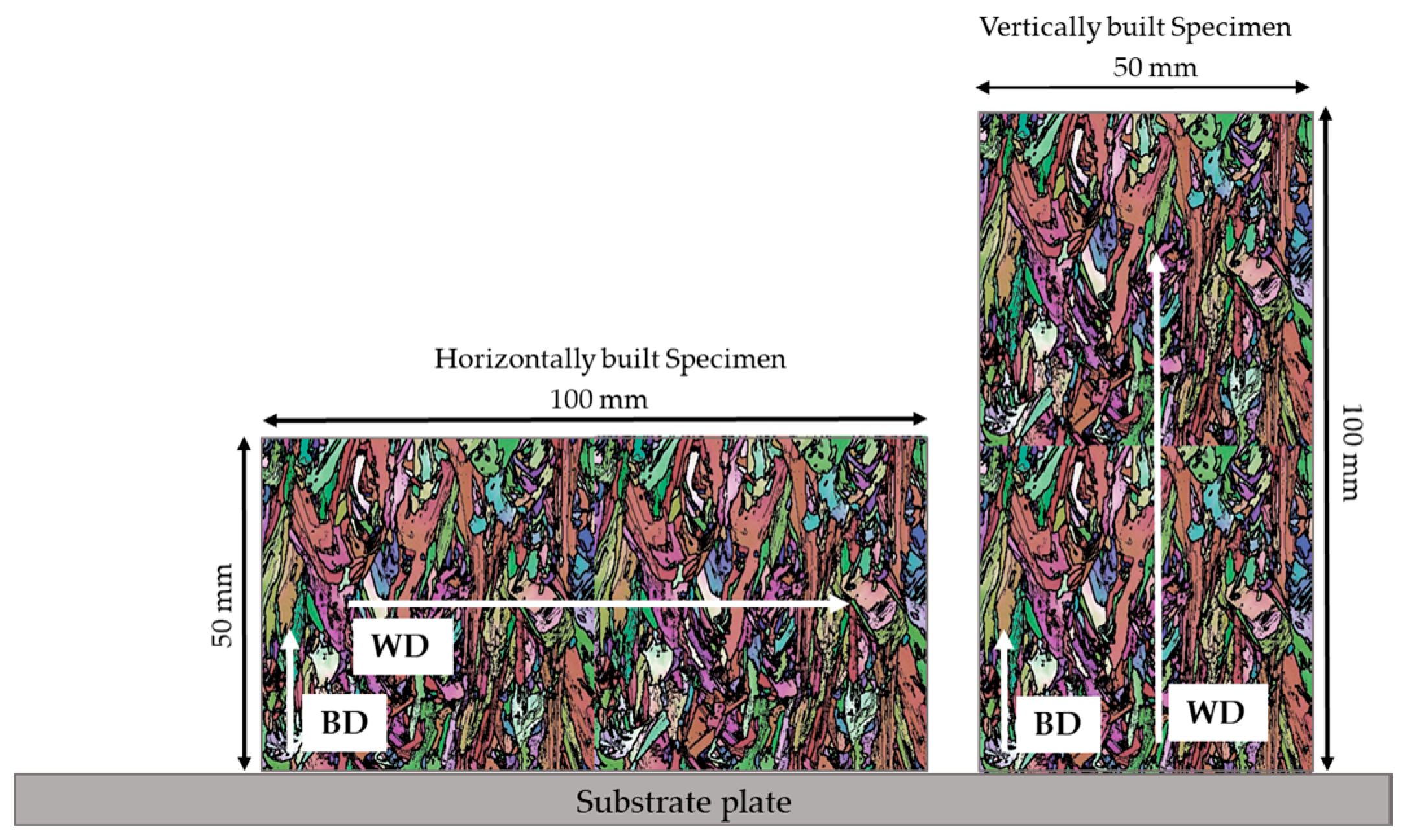
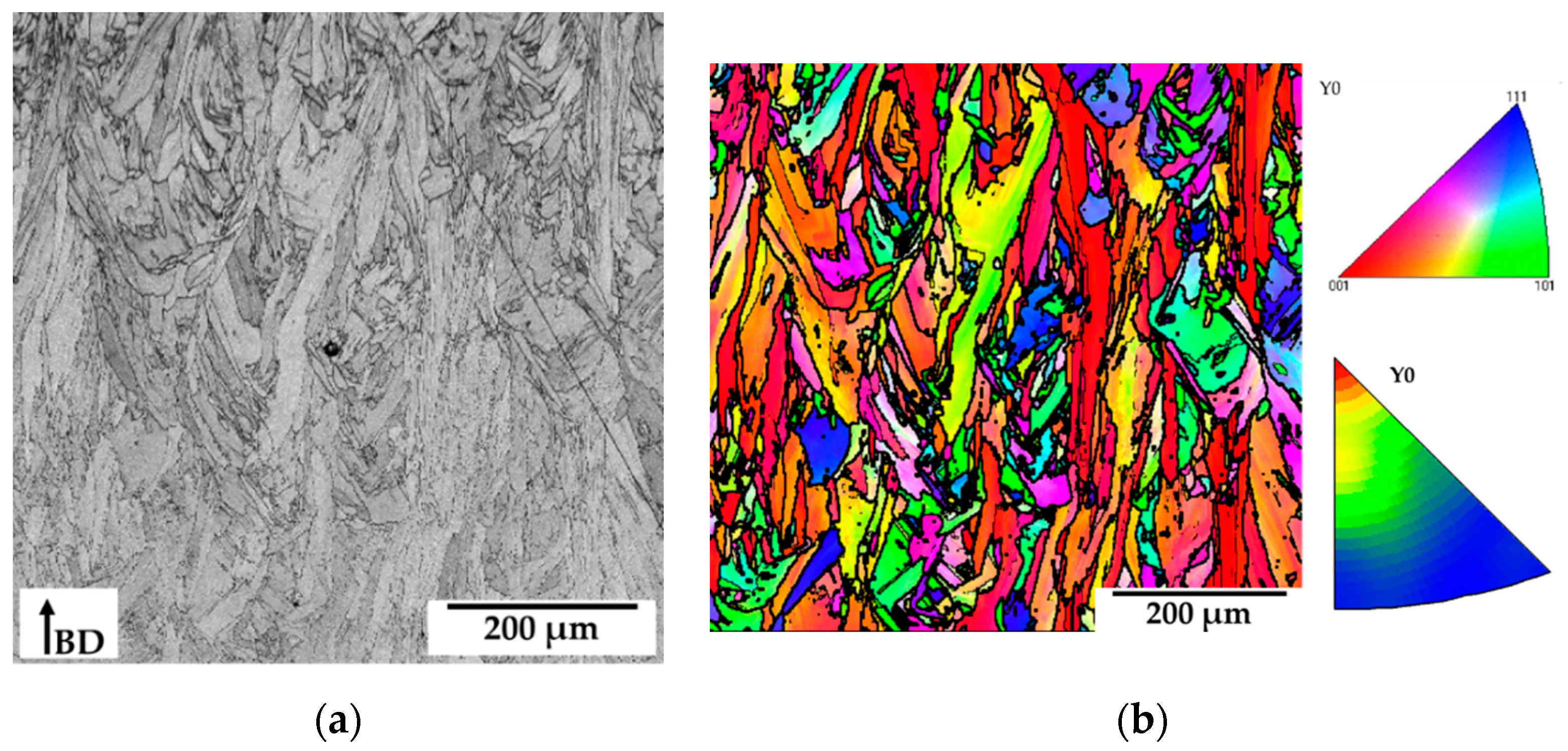
3.1. Evolution of Structure and Texture of the Base Metal

The grains in SLM manufactured parts have a dendritic structure and are mainly oriented in the building direction of the part being built (Figure 1). EBSD mapping was used to determine the grain structure and texture of the parts. These maps reveal, inter alia, grain shape and crystallographic texture of the material. Figure 2a is a SEM image of the unetched microstructure showing grain orientation parallel to the building direction (BD). Figure 2b is EBSD inverse pole figure (IPF) coloring mapping of the same image as 2a. The color key representing the crystal orientation and IPF is given on the right side of the Figure 2b. The IPF color map was plotted with regard to Y (BD) direction. Thick black lines represent high angle grain boundaries with θ > 15° misorientation, while the thin black lines represent low angle grain boundaries (5–15°) misorientation. The microstructure observed in the sample consisted of columnar grain structure with a preferential grain growth in <001> orientation parallel to the building direction.

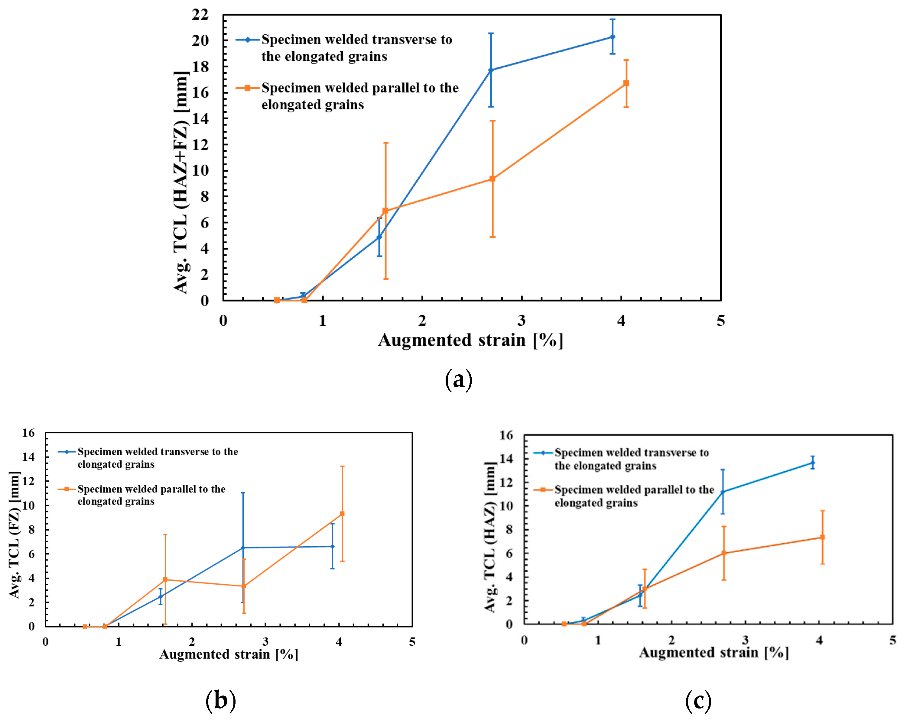
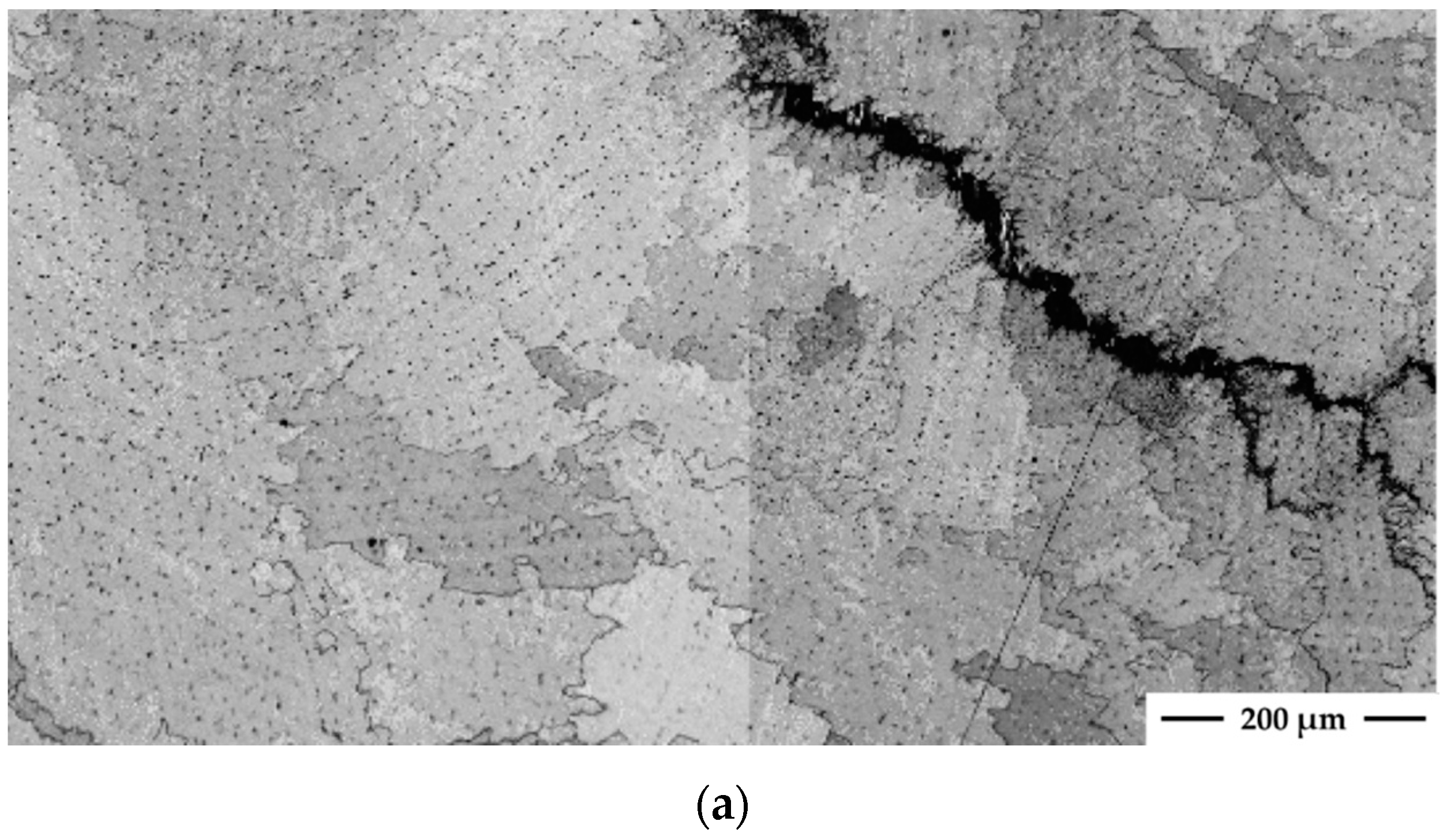
3.2. Evaluation of Weldability and Microstructural Analysis of Welds

The hot cracking susceptibility of the welds was evaluated by crack measurements on each welded sample after a Varestraint test. The average of total crack length versus augmented strain of the samples welded parallel and transverse to the elongated grain orientation is shown in Figure 3. Figure 3a shows the susceptibility to form hot cracks, both in HAZ and FZ. The magnitude of TCL is larger at higher strain levels (3% and 4% strain) in the specimens welded transverse to the elongated grain orientation. The threshold strain, i.e. the strain to initiate cracking was between 0.8 and 1.6% strain for both types of samples. Although, the saturated strain, i.e. the level of strain above that TCL does not change, could not be found for any type of specimen in the present study. Figure 3b shows solidification cracks occurring in FZ of the samples, while Figure 3c shows the magnitude of liquation cracks occurring in the HAZ. It can be seen from these figures that a significantly higher degree of hot cracking occurred in the samples welded transverse to the elongated grains, as compared to the ones which were welded parallel to the elongated grains (Figure 3a). Cracking in the FZs (Figure 3b) of both types of the samples had no significant differences in amount but in the HAZ (Figure 3c), it was almost twice as much in the samples welded transverse to the elongated grain orientation, compared to the samples welded parallel to the elongated grains.
Three types of solidification cracks in FZ were observed in this investigation; (i) open cracks exhibiting little or no backfilling, (ii) partially backfilled cracks of moderate size, and (iii) completely backfilled cracks. The crack in Figure 4a is an example of an “open” crack since there is a little or no apparent evidence of backfilling by the eutectic material. Figure 4b is showing a completely backfilled crack and partially backfilled crack.
In the present study, all welded specimens exhibited similar cracking morphology in FZ. Cracks in FZ appeared in a roughly semicircular array outlining the location at the trailing edge of the weld pool on the spot where the augmented strain during Varestraint test was applied. Closer investigation showed that all the FZ cracks were located in the boundaries between individual grains (Figure 4). It is a well-known fact from the welding literature that during solidification the grains at the solid-liquid interface tend to grow in the direction of the maximum temperature gradient [13]. Consequently, cracks propagating in these grain boundaries were oriented perpendicular to the trailing edge of the weld pool.
Most of the cracks in the samples were initiated in the PMZ and were extended away from the fusion line into the HAZ along the grain boundary paths. PMZ is shown in the Figure 5a and Figure 6a with red dashed lines. Some cracks initiated in HAZ too. The EBSD analysis of both specimens demonstrated that crack propagation in PMZ and HAZ always occurred along high angle grain boundaries (Figure 5c and Figure 6c). This cracking behavior was similar in both types of welded samples. According to the literature [12], the high angle grain boundaries are more susceptible to HAZ cracking during welding due to their ability to accommodate a large number of segregated elements, in comparison with low angle grain boundaries, leading to their liquation.
Direction of the grains in HAZ was also found to play an important role for the cracking susceptibility of the material. In the sample welded transverse to the grain orientation (Figure 5) the cracks were longer, widely opened and uninterruptedly occurring along the favorably oriented grain boundaries perpendicular to the FZ. On the other hand, the cracks in sample welded parallel to the elongated grain orientation (Figure 6) were observed to run parallel to the fusion line, and they only occasionally extended farther away into the HAZ. The small number of favorably oriented grain boundaries in the HAZ made crack propagation difficult into the HAZ.
Cracks in the present study were caused by the combination of two main factors; mechanically induced strain due to Varestraint test method and a crack susceptible microstructure. It was observed in the welded samples that cracks initiated in the PMZ which is the region adjacent to the fusion line and where the temperatures are sufficiently high to produce melting along the grain boundaries. During re-solidification in this partially melted region liquation of precipitates, residually existed in the SLM as-built microstructure, occurs [4]. This allows the formation of the liquid on the grain boundaries that become susceptible to hot crack formation upon application of the strain during the Varestraint test.
Thus, it is possible to have less HAZ cracking if the SLM-manufactured material is welded parallel to the building direction and along the elongated grain orientation to avoid high angle grain boundaries favorably oriented transversely in the HAZ.

4. Conclusions

Selective laser melted Alloy 718, manufactured in two different building directions, has been investigated by Varestraint weldability testing method in order to understand the influence of grain orientation on hot cracking susceptibility.
  • The extent of heat affected zone cracking was observed to be smaller in samples welded parallel to the elongated grain orientation than when welding was done transverse to the elongated grain orientation.
  • There was no significant difference relative to the solidification cracking susceptibility in fusion zones of the two orientations.
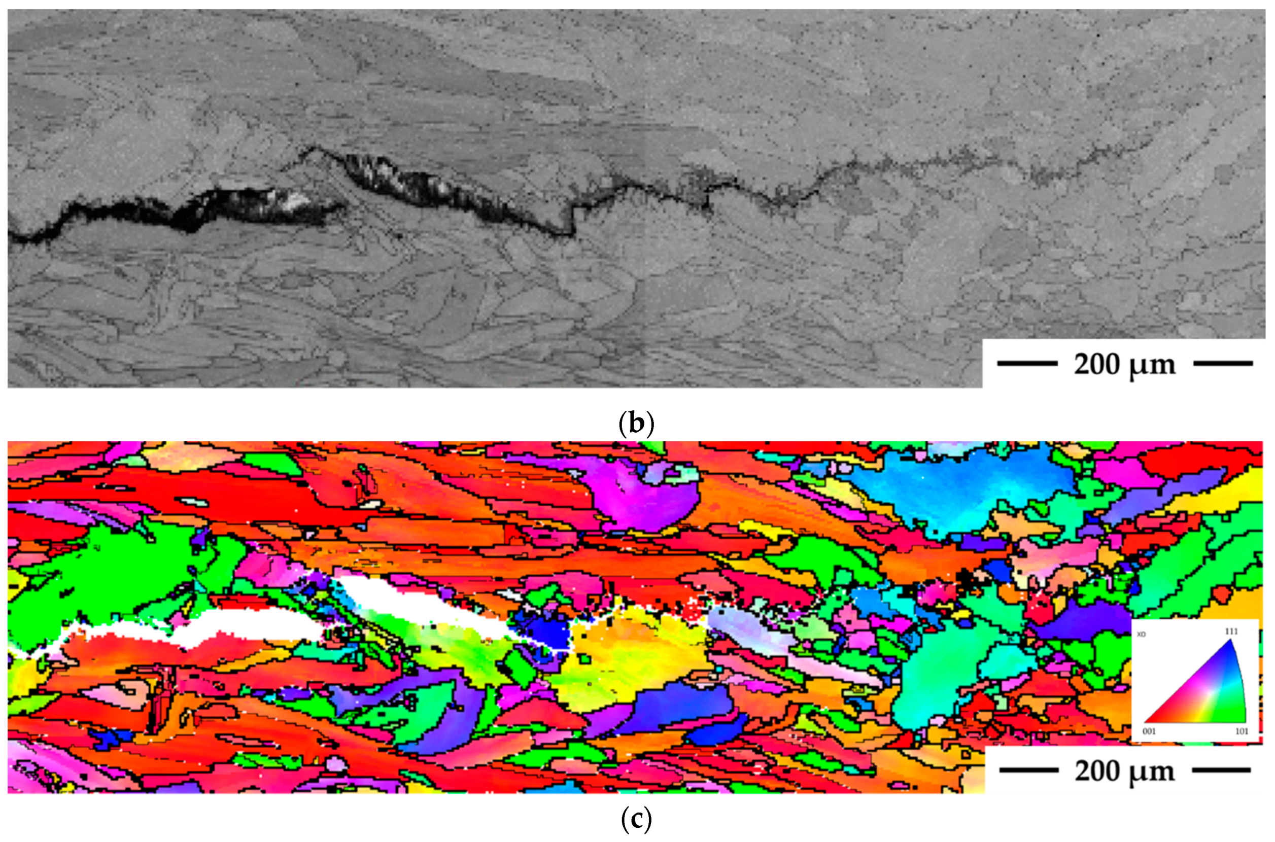
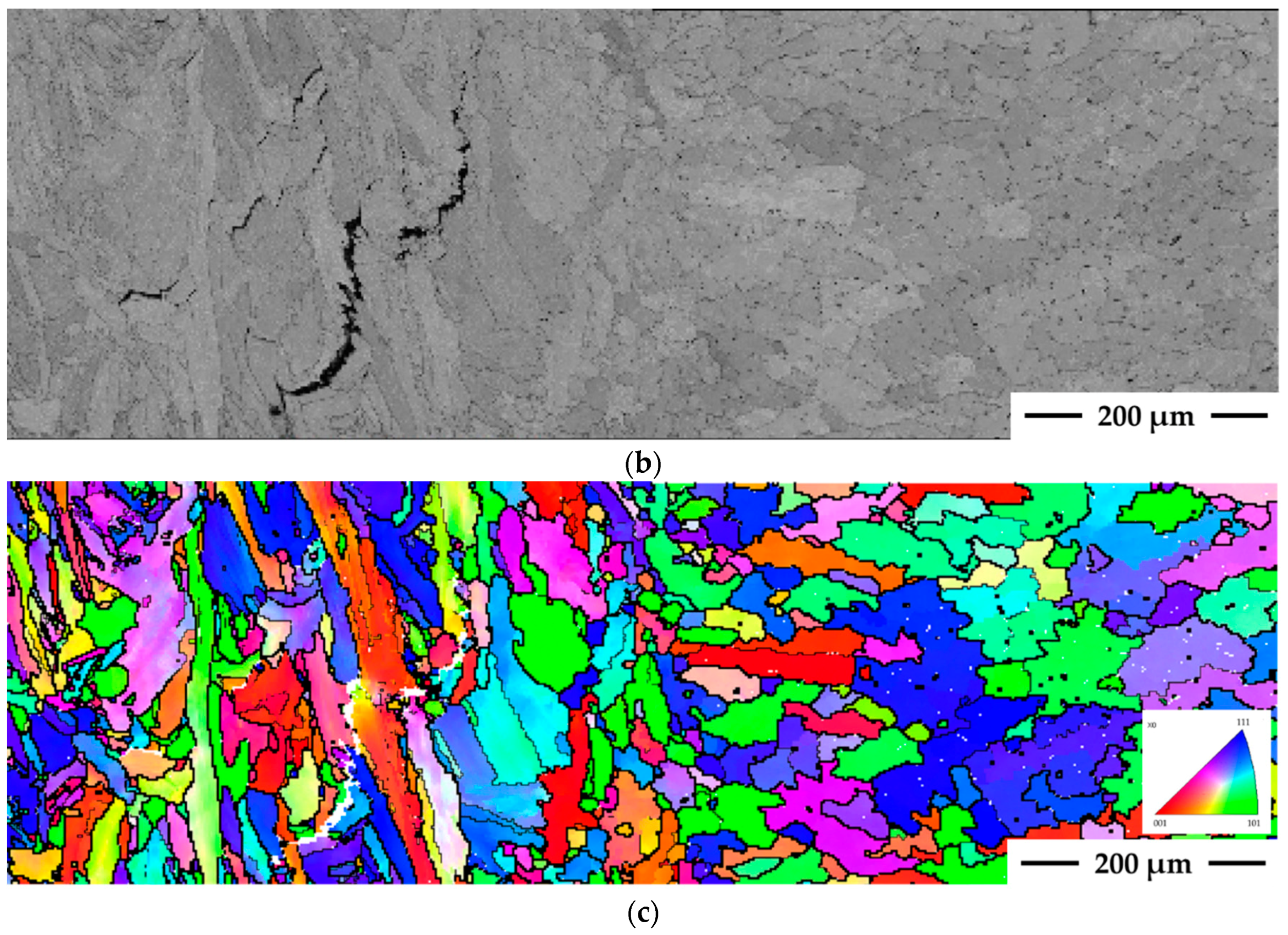
  • EBSD analysis showed that cracking occurred along high angle grain boundaries in both types of samples.

Author Contributions

Conceptualization, investigation, validation and writing—original draft preparation, T.R.; supervision, conceptualization, and editing, J.A. and L.-E.S.

Funding

The authors gratefully acknowledge the financial support from The Swedish National Space Board and VINNOVA (National Space Research Program and National Aerospace Research Program).

Acknowledgments

The authors gratefully acknowledge the financial support from The Swedish National Space Board and VINNOVA (National Space Research Program and National Aerospace Research Program). We also acknowledge GKN Aerospace Filton, United Kingdom for providing us selective laser melted Alloy 718 specimens for the present study. The support and input from GKN Aerospace Sweden AB is also acknowledged. Special thanks to Kjell Hurtig at University West for his help in Varestraint testing and to Nitesh Raj Jaladurgam at Chalmers University of Technology, Sweden for his help in EBSD analysis.

Conflicts of Interest

The authors declare no conflict of interest.

References

  1. DebRoy, T.; Wei, H.L.; Zuback, J.S.; Mukherjee, T.; Elmer, J.W.; Milewski, J.O.; Beese, A.M.; Wilson-Heid, A.; De, A.; Zhang, W. Additive manufacturing of metallic components—Process, structure and properties. Prog. Mater Sci. 2018, 92, 112–224. [Google Scholar] [CrossRef]
  2. Sims, C.T.; Stoloff, N.S.; Hagel, W.C. Superalloys II; Wiley-Inter Science: New York, NY, USA, 1987. [Google Scholar]
  3. Deng, D.; Peng, R.L.; Brodin, H.; Moverare, J. Microstructure and mechanical properties of Inconel 718 produced by selective laser melting: Sample orientation dependence and effects of post heat treatments. Mater. Sci. Eng. A 2018, 713, 294–306. [Google Scholar] [CrossRef]
  4. Raza, T.; Hurtig, K.; Asala, G.; Andersson, J.; Svensson, L.-E.; Ojo, O.A. Influence of heat treatments on heat affected zone cracking of gas tungsten arc welded additive manufactured alloy 718. Metals 2019, 9, 881. [Google Scholar] [CrossRef]
  5. Andersson, J.; Jacobsson, J.; Lundin, C. A Historical Perspective on Varestraint Testing and the Importance of Testing Parameters. In Cracking Phenomena in Welds IV; Springer International Publishing: Berlin, Germany, 2016; pp. 3–23. [Google Scholar]
  6. Owczarski, W.A.; Duvall, D.S.; Sullivan, C.P. A model for heat affected zone cracking in nickel-base superalloys. Weld. J. 1966, 45, 145–155. [Google Scholar]
  7. Baeslack, W.A.; Nelson, D.E. Morphology of weld heat-affected zone liquation in cast alloy 718. Metallography 1986, 19, 371–379. [Google Scholar] [CrossRef]
  8. Kelly, T.J. Elemental effects on cast 718 weldability. Weld. J. 1989, 68, 44-s. [Google Scholar]
  9. Chen, W.; Chaturvedi, M.C.; Richards, N.L. Effect of boron segregation at grain boundaries on heat-affected zone cracking in wrought INCONEL 718. Metall. Mater. Trans. A 2001, 32, 931–939. [Google Scholar] [CrossRef]
  10. Lippold, J.C.; Nippes, E.F.; Savage, W.F. An investigation of hot cracking in 5083-O Aluminum alloy weldments. Weld. J. 1977, 56, 171–178. [Google Scholar]
  11. Sidhu, R.K.; Ojo, O.A.; Chaturvedi, M.C. Weld cracking in directionally solidified Inconel 738 superalloy. Can. Metall. Q. 2007, 46, 415–424. [Google Scholar] [CrossRef]
  12. Guo, Z.; Chaturvedi, M.C.; Richards, N.L. Effect of nature of grain boundaries on intergranular liquation during weld thermal cycling of nickel base alloy. Sci. Technol. Weld. Joining 1998, 3, 257–259. [Google Scholar] [CrossRef]
  13. Chalmers, B. Principles of Solidification. In Applied Solid State Physics; Springer International Publishing: Berlin, Germany, 1964. [Google Scholar]
Figure 1. Schematic depicting the geometry and dimensions of the test specimens. Specimen building direction (BD), grain orientation, and welding direction (WD) are also illustrated in the image.
Metals 09 01113 g001
Figure 2. (a) Scanning electron microscope (SEM) micrograph showing the unetched microstructure of the SLM-manufactured Alloy 718 cross section parallel to the building direction (BD). (b) Electron back scatter diffraction (EBSD) inverse pole figure (IPF) colored and grain boundary map of the same image as (a). The color key representing the crystal orientation is given in the upper right corner and IPF in the lower right corner of the image (b).
Metals 09 01113 g002
Figure 3. (a) Average of total crack length in both HAZ and FZ, (b) in just FZ, and (c) in just HAZ, versus augmented strain, in specimen welded parallel and transverse to the elongated grains.
Metals 09 01113 g003
Figure 4. SEM micrograph showing the unetched microstructure of the fusion zone of the welded sample; (a) showing an “open” crack and (b) showing completely backfilled crack (arrow 1) and partially backfilled crack (arrow 2).
Metals 09 01113 g004aMetals 09 01113 g004b
Figure 5. (a) Optical micrograph showing base metal (BM), heat affected zone (HAZ), partially melted zone (PMZ), and fusion zone (FZ) of the specimen welded transverse to the sample building direction (BD) (Note: the welding direction (WD) is transverse to the grain orientation). (b) SEM micrograph showing the unetched microstructure of the welded sample. (c) EBSD inverse pole figure (IPF) coloring mapping of the same image as (b).
Metals 09 01113 g005aMetals 09 01113 g005b
Figure 6. (a) Optical micrograph showing base metal (BM), heat affected zone (HAZ), partially melted zone (PMZ), and fusion zone (FZ) of the specimen welded parallel to the sample building direction (BD) (Note: the welding direction (WD) is parallel to the grain orientation). (b) SEM micrograph showing the unetched microstructure of the welded sample. (c) EBSD inverse pole figure (IPF) coloring mapping of the same image as (b).
Metals 09 01113 g006aMetals 09 01113 g006b
Table 1. Nominal chemical composition of the gas atomized Alloy 718 powder (wt.%).
ElementNiCrFeNbMoTiAlC
wt.%50–5517–21Bal.4.75–5.502.80–3.300.65–1.150.20–0.80<0.08
ElementMnCoSiCuBMgPS
wt.%<0.35<1.0<0.35<0.30<0.006<0.01<0.015<0.0015

