Next Article in Journal
Modernization and Optimization of Phosphoric Cast Iron Casting
Next Article in Special Issue
The Influence of Pre- and Post-Heat Treatment on Mechanical Properties and Microstructures in Friction Stir Welding of Dissimilar Age-Hardenable Aluminum Alloys
Previous Article in Journal
An Introduction to Wear Degradation Mechanisms of Surface-Protected Metallic Components
Previous Article in Special Issue
Structural Aspects of Execution and Thermal Treatment of Welded Joints of Hardox Extreme Steel
 
 
Correction published on 21 February 2024, see Metals 2024, 14(3), 255.
Article

Internal Material Flow Layers in AA6082-T6 Butt-Joints during Bobbin Friction Stir Welding

1
University of Canterbury, Department of Mechanical Engineering, Christchurch 8140, New Zealand
2
Fakulti Kejuruteraan Pembuatan, Universiti Teknikal Malaysia Melaka, Durian Tunggal 76100, Malaysia
*
Author to whom correspondence should be addressed.
Metals 2019, 9(10), 1059; https://doi.org/10.3390/met9101059
Submission received: 9 August 2019 / Revised: 26 September 2019 / Accepted: 26 September 2019 / Published: 28 September 2019 / Corrected: 21 February 2024
(This article belongs to the Special Issue Characterization of Welded Joints)

Abstract

:
Bobbin friction stir welding with a double-sided tool configuration produces a symmetrical solid-state joint. However, control of the process parameters to achieve defect-free welds is difficult. The internal flow features of the AA6082-T6 butt-joints in bobbin friction stir welding were evaluated using a set of developed reagents and optical microscopy. The key findings are that the dark curved patterns (conventionally called ‘flow-arms’), are actually oxidation layers at the advancing side, and at the retreating side are elongated grains with a high-density of accumulation of sub-grain boundaries due to dynamic recrystallization. A model of discontinuous flow within the weld is proposed, based on the microscopic observations. It is inferred that the internal flow is characterized by packets of material (‘flow patches’) being transported around the pin. At the retreating side they experience high localized shearing at their mutual boundaries, as evidenced in high density of sub-grain boundaries. Flow patches at the advancing side are stacked on each other and exposed to oxidization.

Graphical Abstract

1. Introduction

Bobbin friction stir welding (BFSW) is an innovative variant of the friction stir welding (FSW) process [1], whereby a double-sided rotating tool physically ploughs along the interface of two butted plates [2] without needing the backing anvil and the axial force during the process [3]. The dynamic interaction between the workpiece and the non-consuming tool creates a severe friction condition at the contact interface [4]. Consequently, significant heat is generated due friction which can locally soften the workpiece material sufficient for plastic yielding and stirring at the bonding track [5]. The stirring action arises from the rotation speed (ω) and advance speed (V). While the tool advances along the weld line (Figure 1), the mutual interaction of the speeds (ω, V) transports the softened mass from leading edge of the rotating tool to be deposited at the rear or trailing edge of the tool [6].
The side of the weld-seam where the direction of tool rotation is the same as the tool progress is called the advancing side (AS) and the opposite side of the weld-seam is the retreating side (RS) [7]. The region located between the AS and RS borders, named the stirring zone (SZ) [8], experiences a thermomechanical plasticizing and then deposition and consolidation in the weld locus [9]. The adjacent region outside the SZ is called the Thermo-Mechanical Affected Zone (TMAZ). The microstructure of this region is formed by the stress-strain fields and heating flux which are induced by the friction and heat generation effects of the stirring action [10]. The next region between the TMAZ and the Base Metal (BM) is the Heat Affected Zone (HAZ). This region is exposed to thermal fields of the stirring process which alter the microstructure [11].
Comparing with the Conventional-FSW (CFSW), in the BFSW the fully-penetrated pin requires more control during the process, as an inconsistency between the process variables can cause more severe failures. The double opposing shoulders system provide a greater contact surface for the frictional heat generation from both sides of the workpiece [9]. The process also replaces the CFSW backing or anvil support plate with the BFSW rotating shoulder at the lower side of the workpiece [12,13]. The CFSW case requires a downward axial load [14] on the tooling, whereas the BFSW requires a compression ratio [15] (the variance between the inner edge-to-inner edge biting gap of the shoulders and the actual thickness of the plate). These differences cause differences in the flow regimes of the two processes [16,17]. In the FSW literature, the onion rings in the conventional-FSW weld structure have been attributed to discontinuous flow during tool-material interaction [18].
As the temperature in FSW processes is lower than in fusion welding, it is categorized as a metal forming process [19]. The internal flow regimes related to the plasticized mass play the main role in the welding mechanism rather than metallurgical transformations of melt-and-solidification. In general, the FSW technique is proposed for materials with a high capability of the dynamic plastic deformation. Aluminium that responds well to large plastic deformation is a good candidate material for FSW. In particular, marine grade AA6082-T6 aluminium alloy with good machinability properties would be attractive to be processed by the BFSW, but shows poor weldability in the conventional fusion welding. One of the obstacles to a better understanding of the actual flow regimes is the need to visualise the details of the flow features for the cross section of the weld [8,20]. This is challenging for AA6082-T6 alloy as the weld region responds poorly to conventional etchant reagents [21]. This problem arises because of the low contrast between grains and grain boundaries for the AA6082-T6 microstructure where the precipitate particles are uniformly dispersed within a supersaturated solid solution treated by artificially ageing per the T6 cycle. Also, severe plastic deformation and grain fragmentation during the BFSW process reduce grain size to ultrafine.
While there is an extensive literature on the microstructural characteristics of the FSW welds [22], the flow mechanism also needs to be identified within the weld structure [23,24,25]. In this regard, there have been attempts to elucidate the heat flow [26] and material flow [27] mechanisms in BFSW, as it is expected to be different to conventional-FSW [28].
The aim of this work is to identify the causality between flow regimes and physical defects. The approach is to visualise plastic deformation features of AA6082-T6 BFSW welds with new etchants [21], using optical metallography. These reagents show the details and complexity of the plastic flow patterns within the stirring zone, even when there is an element of grain refinement due to the thermomechanical plastic deformation. A benefit of this approach is achieving a detailed microstructural analysis with conventional etching methods and optical metallography, rather than the more costly processes of electropolishing, or electron metallography (e.g., SEM, EBSD, and TEM).

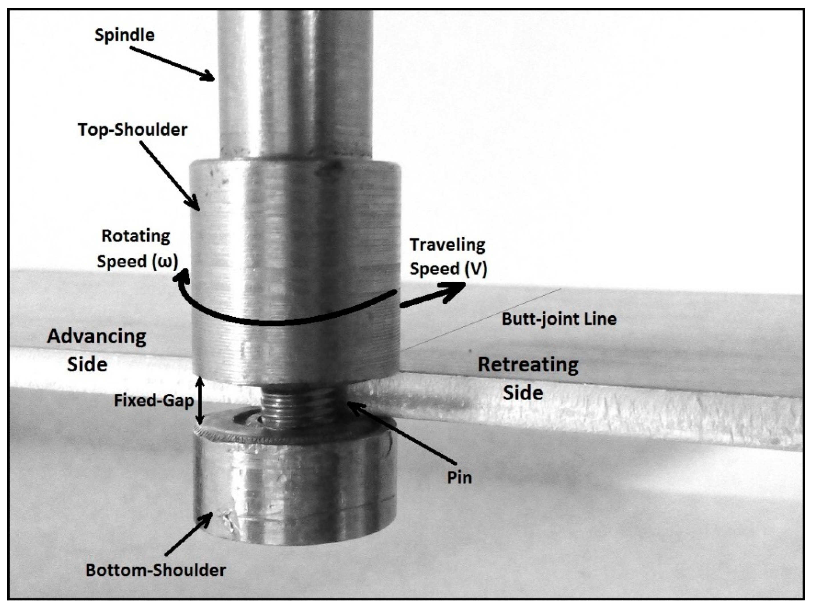
2. Materials and Methods

For the weld trials, rolled plates of AA6082-T6 (Al–Si–Mg–Mn family) were used as the workpiece. The chemical composition of the AA6082-T6 aluminium alloy as the base metal is reported in Table 1.
BFSW tests were conducted using a geometrically full-featured (including threads, flats and scrolls) bobbin tool manufactured from H13 tool steel with hardness of 560 HV. The butt-joint weldments comprised two pieces of similar plates with dimensions of 250 mm (length) × 75 mm (width) × 6 mm (thickness). The welding trials involved two sets of operation speeds; spindle rotational speed (ω) and weld travel rate (V).
The aim of the research was to identify the flow features of the BFSW weld in a defect-free structure compared with the presence of defects. A sample of each condition was procured. The defective weld was produced with welding parameters of ω = 400 rpm, V = 350 mm/min. The good weld was produced at ω = 650 rpm and V = 400 mm/min. The same tool was used in both cases. These process parameters were identified from previous work [30]. That reference also describes the tool geometry in detail, see also Table 2.
The BFSW experiments were performed on a 3-axis CNC machining centre (2000 Richmond VMC Model, 600 Group brand, Sydney, Australia) with a Fanuc control unit and 14-horsepower spindle motor capacity. There were no preheating or post-weld processes before or after the welding process. The direction of tool rotation was clockwise relative to the advancing direction of the welding (Figure 1). Table 2 gives more details of the bobbin-tool and the welding operation. After welding the quality of joints were first checked by visual examination, and then cross sectioned by an electro-discharge machine wire cut through the middle of the weld seam (perpendicular to the welding direction). The resulting surfaces were subjected to metallographic measurements. For metallographic analysis, firstly the specimens were prepared using standard mechanical polishing with different grades of SiC sand papers (600-grit, 800-grit and 1200-grit). To achieve a mirror surface, the micro-polishing step was conducted on a micro-cloth pad with a 3 µm diamond paste, and finally a 0.05 µm colloidal silica solution. The etching process was designed to remove the oxide film, and then delineate the flow lines. The polished specimens were first pre-etched for 3 min in a solution of (5 g NaOH + 1 g NaCl + 80 mL H2O) at 70 °C. The developer mixtures are shown in Table 3, which describes the composition and other conditions of the chemical solutions (time and temperature). After completion of the etching process, the samples were rinsed in ethanol, and then dried with warm air. The flow patterns of the BFSW weld region were studied using stereoscopic and light optical microscopes (Olympus Metallurgical Microscope, Tokyo, Japan). In some cases, where the microscopic features needed to be clarified in more detail, the cross-section sample was re-polished and re-etched with other reagents. For some metallurgical validating, the etched samples were also subjected to elemental mapping using the scanning electron microscope (SEM) (JEOL 6100, JEOL Inc., Peabody, MA, USA) equipped with energy-dispersive X-ray spectrometer (EDS) detector (Oxford Instruments plc, Abingdon, UK).

3. Results

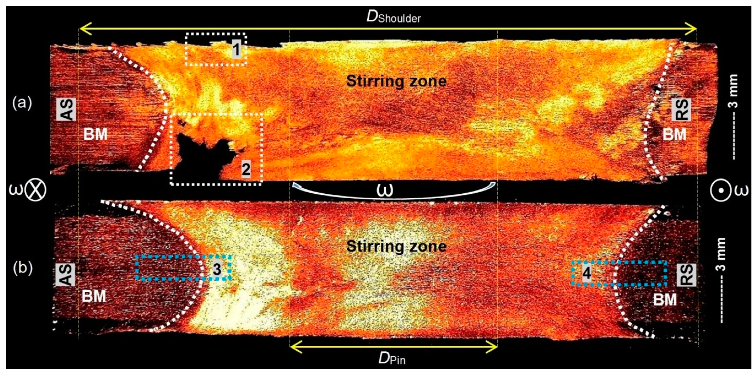
3.1. Macrostructure of the Cross-Section

Figure 2a,b reveal the macrostructural examinations of the AA6082-T6 BFSW joints (etched by Reagent A) for two different sets of welding speeds (longitudinal or rotating), refer to Table 1. Both joints exhibit a distinctive zone in the middle, processed by thermo-mechanical plastic deformation induced by the bobbin-shaped tool. This hourglass-shaped region—different from the basin-shaped SZ in CFSW [13]—is discernible in the middle of the weld from the base metal (BM) by the symmetrically curved borders at the both advancing side (AS) and retreating side (RS).
It is observed that the SZ, at the middle of the weld, is larger than the diameter of the pin. This is attributed to: (a) the pin recruiting a wider volume of matter through frictional contact with the substrate, and (b) recruitment of the substrate material via frictional heating from the shoulders. Both the pin and shoulders create frictional heat.
Basically, in BFSW the fully contained pin has eliminated the incomplete root penetration of CFSW, but in Figure 2a, a macro-size tunnel void has emerged at the bottom surface towards the AS, while Figure 2b shows a defect-free weld with an integrated structure. The origins of tunnel void emergence are not fully understood in the literature; however, it is clear that the formation of this macro-size defect in a solid state process does not seem to be more definite to have a metallurgical explanation. Existing theory attributes the tunnel voids to incomplete backfilling [8,31], that arises from incompatible welding speed parameters (ω, V), or dynamic interaction between the tool and workpiece [31,32]. It appears that there is insufficient material. As the metallography samples were cross sectioned from the middle of the weldment, the amount of the material loss can be considered similar to the size of the sprayed tail defect at the entry zone. The continuous tunnel void shows that the plates were not fully butted.
From observation of the macrostructure, we infer the existence of the internal flow directions. This can affect the weld quality, when the failure of the flow regimes leads to the emerging of the defects (e.g., tunnel voids or hair-line micro-cracks). To provide a better explanation for the origins of the defects based on a flow-based observation, the metallographic measurements needed to be conducted in more depth with a focus on microstructural and flow feature integrity.

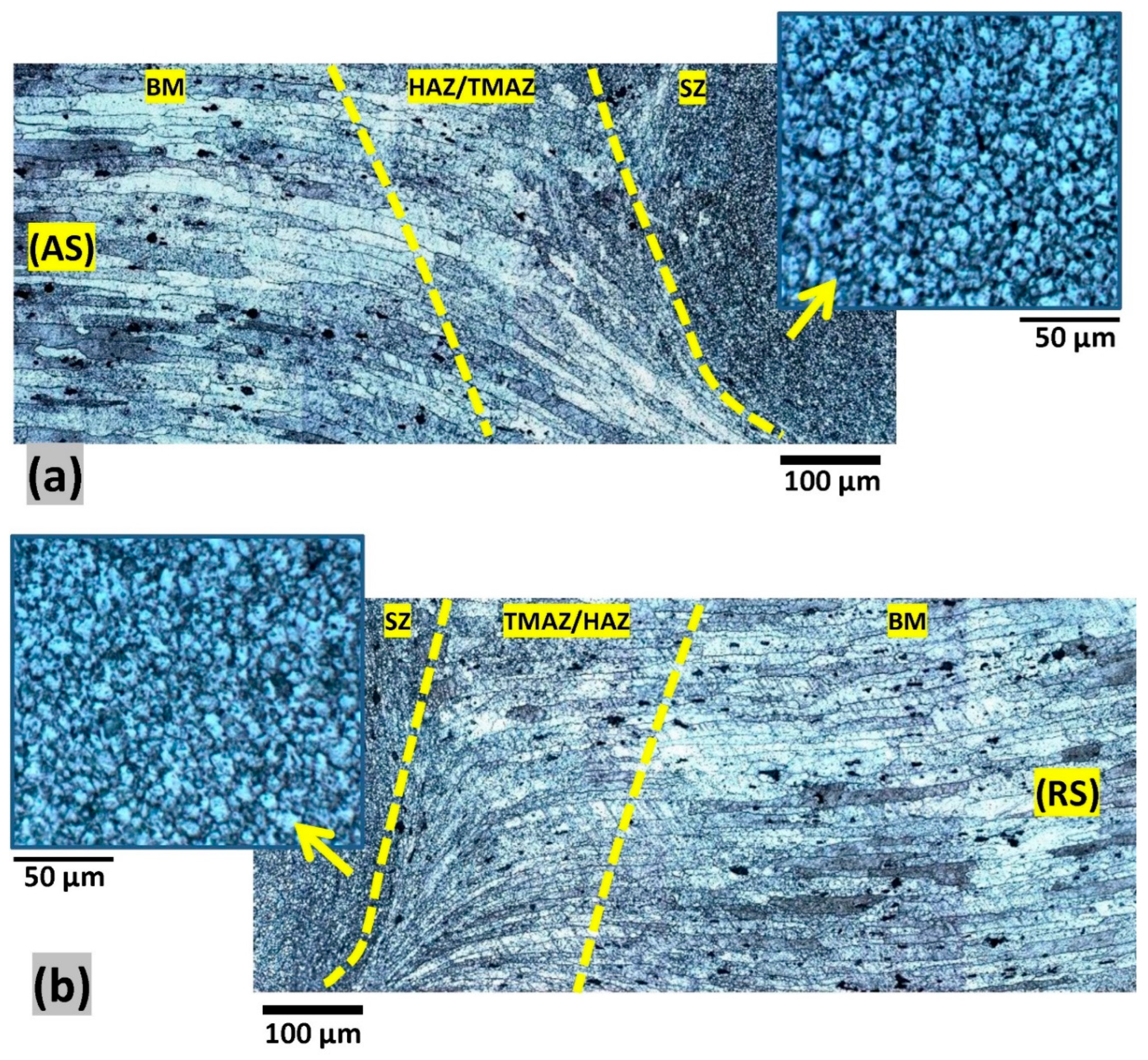
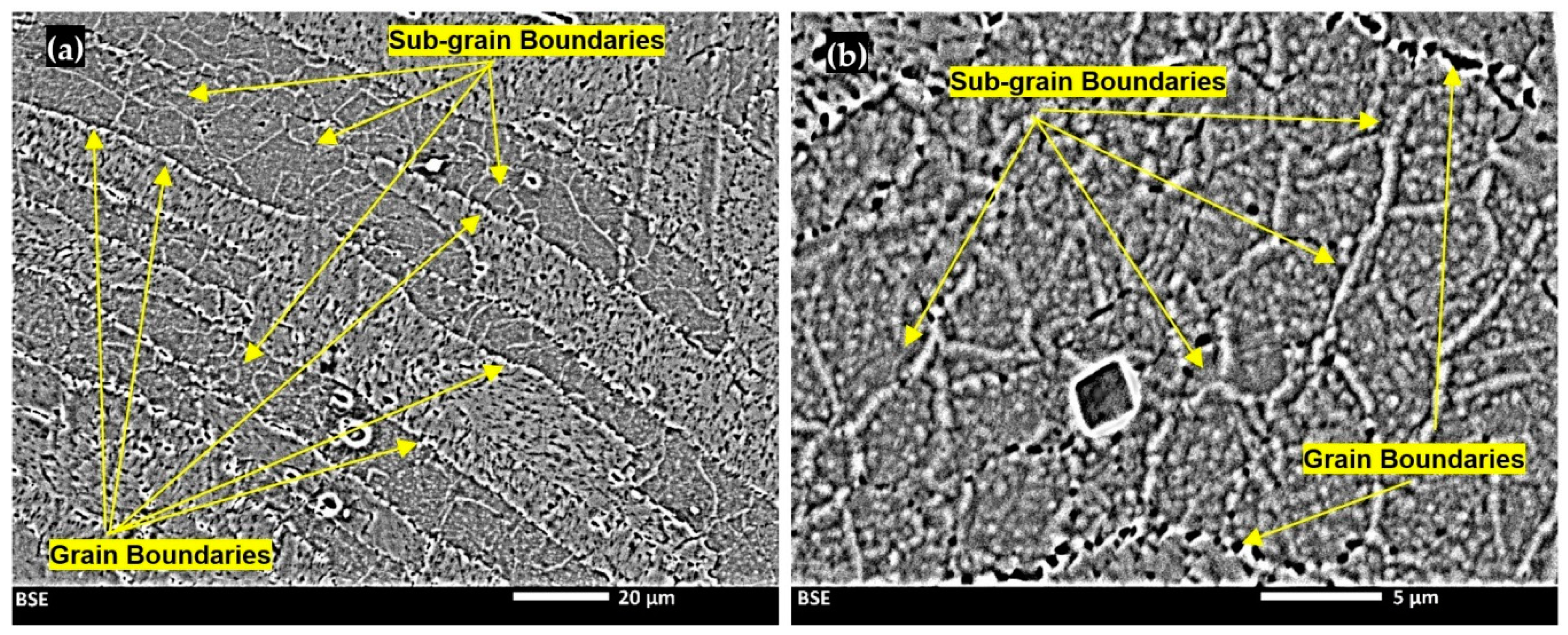
3.2. Microstructure Evolution

The transverse section of a BFSW weld-seam should reveal three typical zones; HAZ, TMAZ and SZ, distinguished from the BM towards the centre of the weld. However, macro-sections of the BFSW welds (Figure 2) only indicated a primary macrostructural region for the stir zone (SZ) at the centre of the weld. The other transitional zones could not be identified using macro etching. To make the TMAZ and HAZ regions visible we re-polished, used etchant B and higher magnification for the micrographs and then montaged them together.
Figure 3 shows a photomontage of the micrographs taken from the transverse cross-section of the BFSW weld (selected from the sample of Figure 2b) close to AS and the RS hourglass boundaries, etched by Reagent B. This reveals the deformation-induced grain refinement at the transition region (HAZ/TMAZ) on either side of the SZ.
The latter region exhibits a grain orientation transformation. The transformation is represented in grain size and morphology. The transition region has rotated-elongated grains morphology detectable with a distortion in grains compared with the parent material. Compared to the large columnar grain structure of the BM, the microstructure of the SZ reveals a homogenous distribution of the fine equiaxed grains. This abrupt change in structure separates the TMAZ/HAZ region from the plastically deformed finer-grained SZ, and the large directional grains observed in the BM structure. This is attributed to dynamic recrystallization (DRX), which in turn arises from the thermomechanical (heating & strain) mechanisms during stirring.

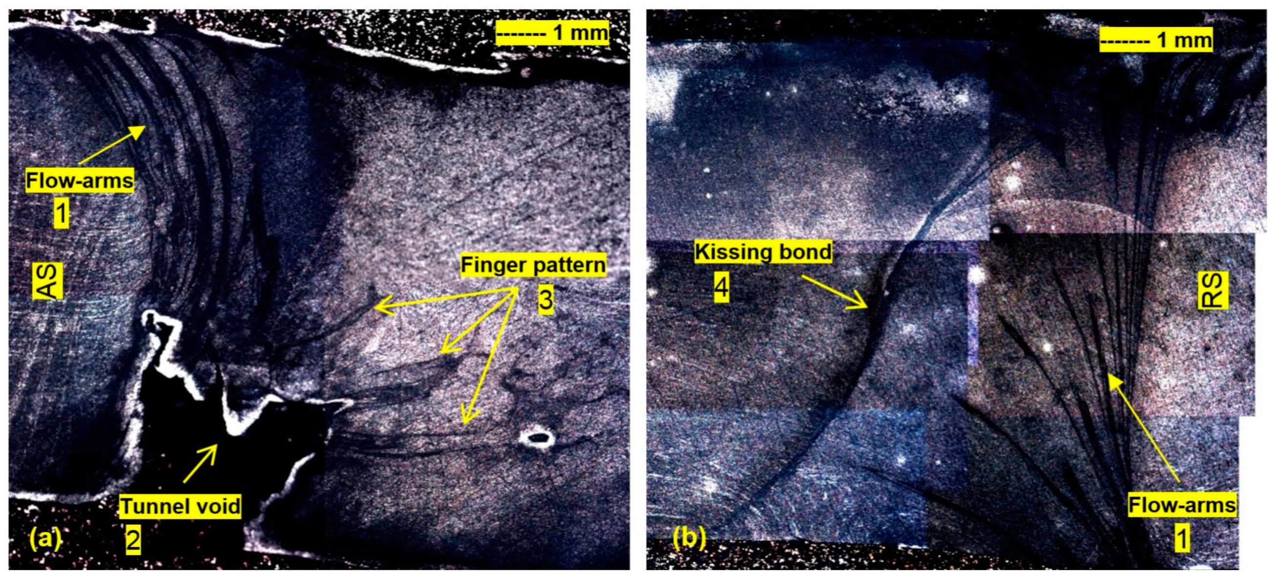
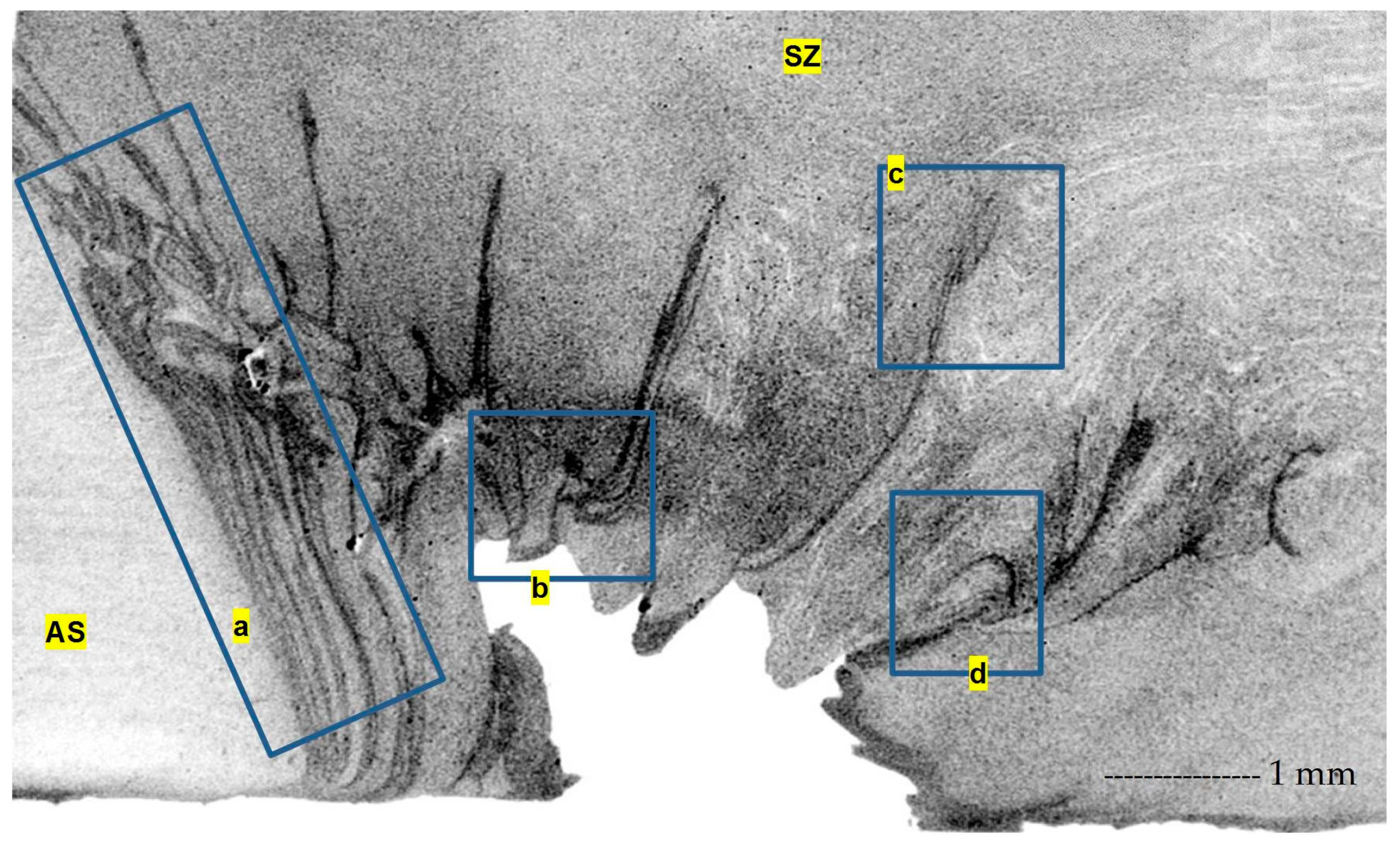
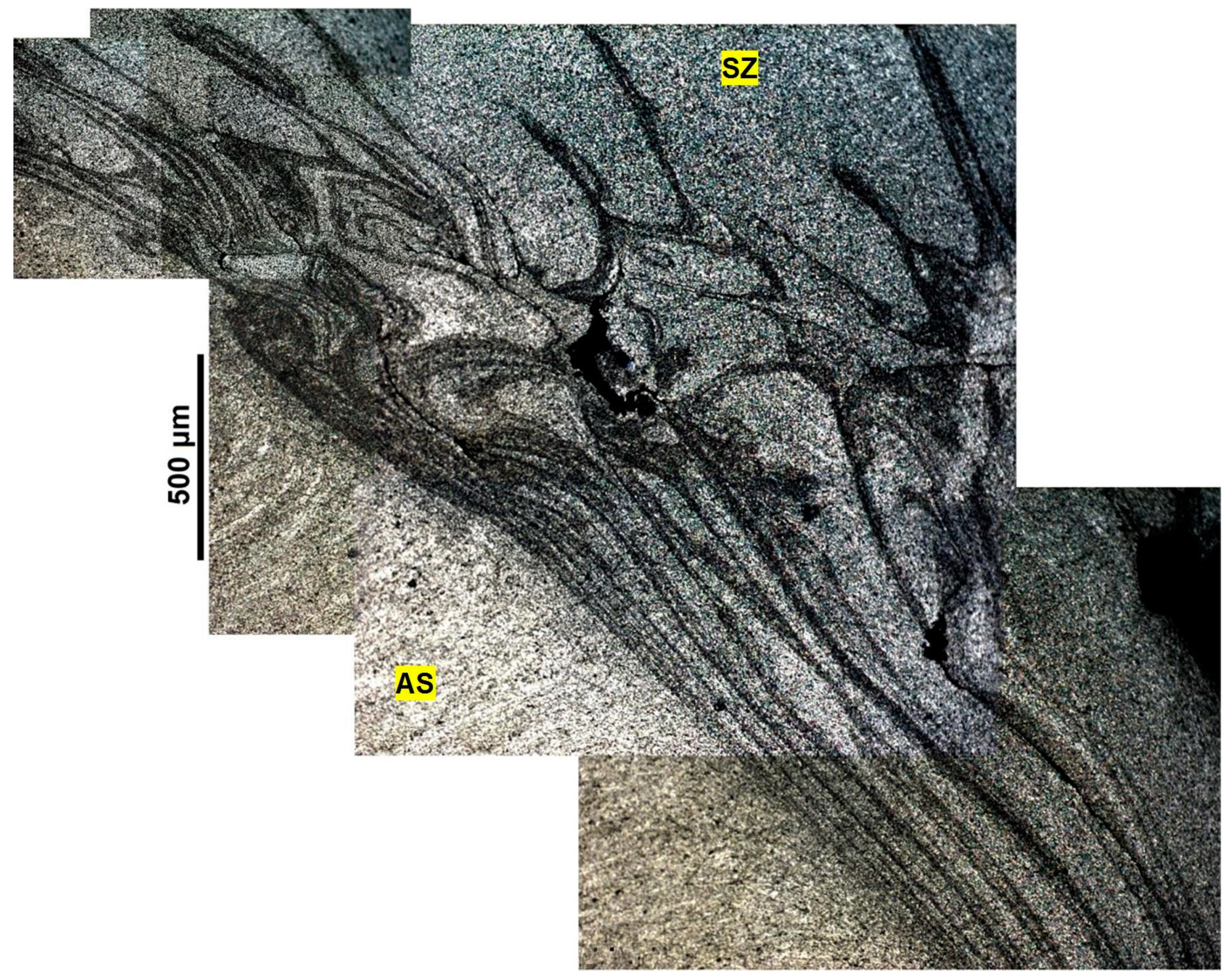
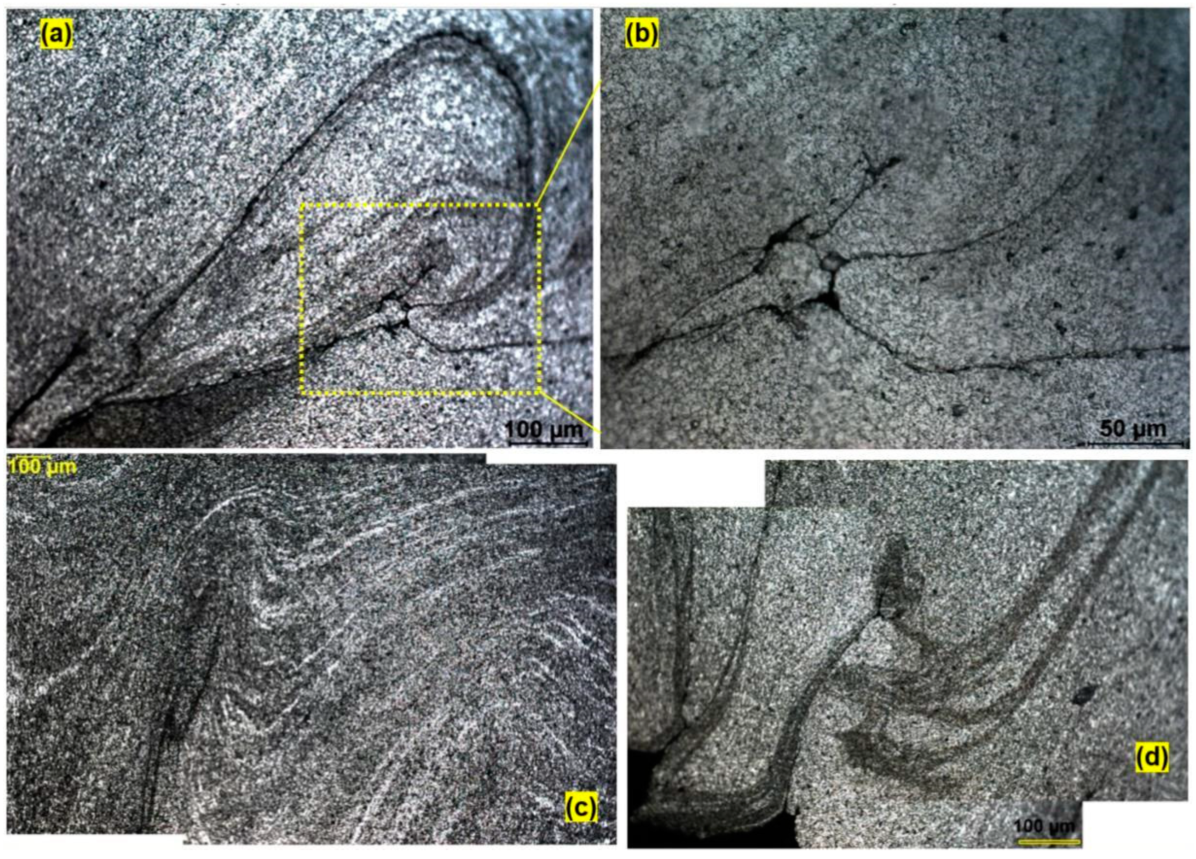
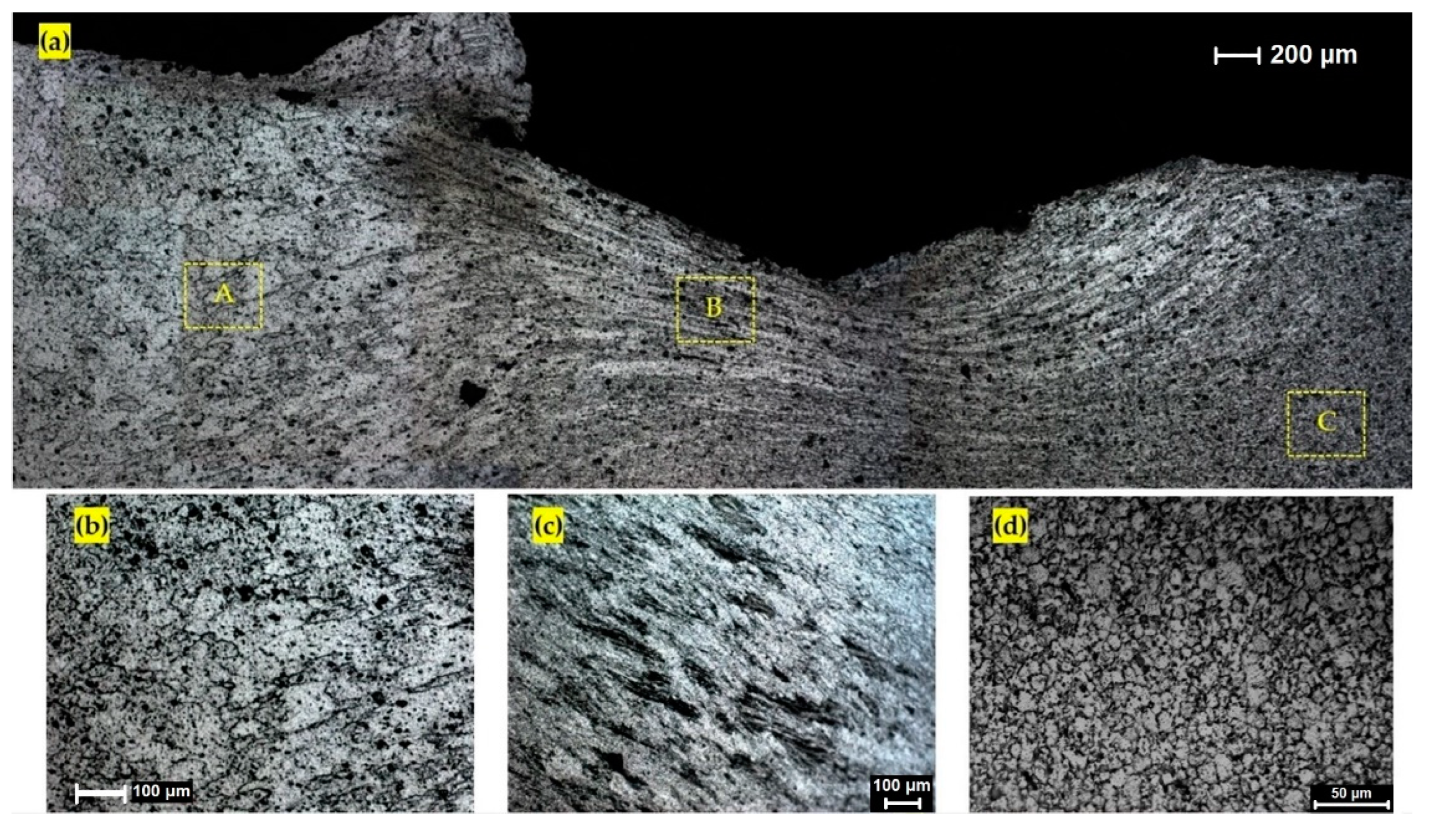
3.3. Material Flow Features in the Weld Cross-Section

The magnified micrographs in Figure 3 from the interface of the SZ and the external region illustrate a metallurgical bonding between the processed weld region and the parent metal. To distinguish the flow patterns from the grains structure, etchant reagent C was used, giving the results in Figure 4.
For this micro-flow evaluation, the sample of Figure 2a was chosen to reveal more details because of the existence of defects (e.g., tunnel void). As is shown in Figure 5a,b, the presence of the flow arms (banded patterns) is evident in the SZ at the hourglass borders for both sides of the weld. The flow arms of the AS are more compacted to each other.
The flow arms become dispersed when reaching the tunnel void (Figure 4a). In this case, the flow arms near the bottom surface of the weld follow a finger pattern, stretched from the hourglass boundary (at the circumferential edge of the tunnel void) towards the centre of the weld. It is more evident that the compaction effect from the top shoulder was higher than the bottom shoulder, while their diameters and contact surface conditions are the same. The branching pattern can also be observed when the plastic flow behaviour—between the bottom and top surfaces—is affected by the geometrical features of the tool (threads, flats, scrolls) during the stirring action. We attribute this to an unsteady internal flow, in turn caused by the inability of the flow to completely fill the void left by the tool moving forward. Behind the tool, the material moves from the RS towards the AS, and is deposited at the AS. If there are any insufficiencies in the flow, due perhaps to previous loss of material at entry, or early cooling of the material, then the forward movement of the tool creates a gap that is difficult for the flow to fill. We attribute the striation layers themselves to batches of material cut by the flats out of the base material.
The macro-section of the bobbin weld in Figure 4b reveals another distinct flow-based problem. The appearance of this linear discontinuity is similar to the kissing bond defect in CFSW; solid-state bonding with poor or no metallurgical adhesion. One of the major causes of kissing bond defects in friction stir welds is insufficient engagement of the tool pin into the plasticized material. We interpret the current findings as due to a recoil/backlash between the pin and the material during the stirring, (such as might be caused by vibration – which was prevalent), causing incomplete joining. It should be noted the kissing bond defect is more prominent in samples produced at lower rotational speeds which can be attributed to the inconsistency in strain distribution due to occurred flow-based condition. Furthermore, the position of the kissing bond defect is located exactly at the position of change in the flow direction from leading edge to the trailing edge of the pin.
It is very difficult to detect or accurately characterize the nature of this defect by the typical analysis methods, e.g., metallography or non-destructive testing (NDT). However, in Figure 4, we tried to delineate the exact location of the discontinuity line in the microstructure by Reagent C. As it is observable in Figure 4b, a continuous and uniform discontinuity flow was vertically delineated between the top surface and bottom surface through the SZ. Furthermore, this microscopic view confirms that the nature of the defect line is not a grain structure.
We propose that it is a kind of oxidation formed during the dynamic recrystallization of the deformed grains. The proposed explanation of is as follows: As the pin possesses a symmetrical thread-flats feature acting through the stirring zone, the rotating angle between the flat surface and the thread surface creates an empty space to allow air to enter into the weld region. During the stirring, which is at considerable temperature, this air causes a surface oxidation between the layers of stirred mass from the AS. Possibly the adiabatic compression of air pockets adds further heating.
The darker colour of the flow arms -visible in hourglass borders and around the tunnel void- is also attributed to this oxidation behaviour. In addition, it should be noted that this oxidized layer was formed in the sample containing the tunnel void defect, but not in defect-free samples (no tunnel void). Therefore, another flow-based relation can be assumed between the emergence of the tunnel void in the AS position, and formation of this oxidation bond at the RS proximity of the stirring zone.
While the pin-driven pressure force in the tunnel void region is insufficient to refill the position by a compensating flow, in the RS the pressure is high, which consequently squeezes the flow to the trailing edge of the tool. By revolution of the tool these oxidation bonding layers can be stretched/transferred also towards the RS. However, there is less compaction between the flow-arms at the RS and the refilling action and deposition of the stirred mass at the RS does not lead to a discontinuity at the RS.
We suggest the defects and oxidation layers have flow-based origins. Due to the clockwise rotation of the tool, the plastic flow behaviour differs in AS and RS of the SZ. As in the AS the rotation of the tool was in the direction of welding advance, the plastic deformation of the BM moves forward (and approaches the leading edge). Simultaneously in the opposite direction of the tool (RS), the extrusion nature of the process causes the plasticized flow to become squeezed through the region between the tool and base metal. This forms a channelized flow, which is transferred backwards on the trailing edge of the pin.
Similar to a kissing bond, this oxidation bonding likely causes a negative effect on mechanical properties of FSW joints. Typically, this brittle-nature defect can affect the fatigue/tensile strength of the weld as it is a stress raiser and eventually a place for initiating the fracture. It is suggested that in the presence of this oxidation layer, the crack initiation location and the crack growth would be mainly along the boundaries of this defect. This can cause a possibility for a failure mode, different to typical fracture in fusion welds.
One of the outcomes of the instability of the internal flow regimes is the emergence of tunnel void. Figure 5 shows micrographs of the AS region to evaluate the flow behaviour around the tunnel void defect.
The corresponding flow arms around the tunnel void and in proximity of AS border are shown in Figure 6 which reveals an intersecting layout from the top surface stretching downwards. The striation diagonal lines around the bay-shaped tunnel geometry (Figure 5) show the simultaneous effects of the pin (thread marks) and shoulders on the plastic deformation. The reason for the tunnel defect being at the bottom surface can be attributed to the action of the right-handed threads on the pin, which pump material upwards. There is also a mass deficit caused by loss of material at edge-entry. This mass deficit persists as a continuous void on the bottom surface.
Direction of the scrolls compared with the tool rotation provides a circulation towards the centre – this is deliberate and is intended to provide a dynamic sealing of the weld. In an ideal condition, threads and flats on the pin and scrolls on shoulders improve the uniformity of stirring by driving the lateral motion and pumping of material inwards, this reduces spilling [30]. To provide a uniform stirring condition in the sub-shoulder area, the spiral scrolled features started from the edge of the shoulders and ended at the proximity of the pin location. Upward pumping of material (driven by the thread effect) also increases the curvature of hourglass border close to the top shoulder. This shows the compaction of the plasticized flow in this region is more than by the bottom shoulder region.
This upwards flow potentially creates an additional frictional contact between the upper shoulder and the workpiece. If so, we would expect that the temperature on the top shoulder to be higher than that of the bottom shoulder. Consideration of grain sizes suggests that this indeed the case [21]. This may further contribute to cooling and stiffening of the flow at the bottom surface.
The aim of Figure 7 is to clarify the role of the pin features (threads/flats) and the welding parameters (ω/V ratio; rev/mm) in occurrence of the tunnel void. As is shown in Figure 5 and Figure 6, a collection of striation lines accumulated at the AS border. These can be attributed to the simultaneous interaction of the pin threads/flats and the speed ratio (ω/V) to form the flow lines pattern. As a rough measure, the speed ratio by rev/mm is a unit of magnitude of the distance between the flow lines which can form the size of each nib in a saw-tooth like pattern (Figure 5) with the same distance between the flow arms. However, the flow complexities cause an interlaced condition for the flow arms which makes it unreliable as an accurate measurement. The pin threads/flats can cause the localization of deformation through the narrow shear zone to form this saw-tooth like pattern at the internal/inward bay of tunnel defect (Figure 5 and Figure 7d).
It is clear that the tunnel void geometry emerged due to a large lack of bonding, presumably due to the influence of insufficient pushing of material flow during the stirring. Hence, the tunnel void formation is attributed to insufficiency in compaction of the material flow at the position of the defect. This indicates that for a good weld the material must have good flow forced by the tool geometry and process variables.
The typical periodic striation lines with the finite width at the border of the AS show the typical forging zone around the pin. These flow lines form a projected area at the circumferential side of the tunnel void where the bonding patterns interlaced abruptly. Our interpretation is that, as the bonding lines are separating, the flow velocity gradually decreases which eventually comes to a sharp decrease at the interface of the tunnel defect. This can also change the orientation of the material flow lines, as the interval of the flow lines is maximally separated (compared to the compacted banding pattern in the proximity of the AS border in Figure 6).
By comparing the lack of bonding defect with the characteristics of a proper joint geometry, the main reason for formation of the tunnel void appears to be insufficient frictional heat and integrity of material flow, due to the internal force and rotating speed during the process. Poor material flow is attributed to an insufficient heat input, which leads to more bonding defects. Also, the compression ratio is not enough to create a consistent forging/pressure force to extrude the plastic mass and fully/decently compensate/refill the defect position.
The curved striation lines in Figure 7a (region d in Figure 6) elucidate these flow-based problems where the connection of the flow lines with the main regime has been disrupted. This leads to formation of a tangled flow around the saw-tooth like pattern at the circumferential side of the tunnel void. As shown in Figure 7b, this tangled flow is a suitable place for stress concentration within the layers of the mass flow, in which may cause microcracking. The propagation of microcracks could eventually lead to the failure of the weld by coalescence of the macrosize voids. The interlaced flow-lines in Figure 7c show a stretched finger pattern (region c in Figure 6) which was evident before in Figure 5a. This flow defect, similar to the curved flow pattern shown in Figure 7a (semi-circular swirling band), can affect the flow integrity as a suitable position for imitation of the micro-crack.
Another flow feature, the enlarged micro-flow shown in Figure 7d, reveals the hook line flow patterns positioned at the internal edge of the tunnel void. We interpret this feature as a lack of material consolidation during stirring, similar to the root flaw in CFSW.
From a metallurgical viewpoint, there is some debate about the nature of the flow-arms as the elongated flow bands with a different colour compared to the matrix. They are not metallographic stains or over-etching. Nor are they some type of intrinsic defects of the base metal formed during the rolling procedure. Rather they are specifically associated with the tunnel defect, and visible across multiple different welds. The literature generally terms them flow lines, i.e. attributes them to internal flow of the material. To further understand the nature of the flow-arms we applied elemental mapping via EDS to determine the composition of the texture. To observe the exact position of the flow-pattern, the samples after etching were observed by Backscattering Electron (BSE) imaging via SEM microscopy, also supported by the elemental mapping via the energy-dispersive X-ray spectrometer (EDS) detector. The scanning analysis was done for the flow-arms region, also the selected location of the hair-line micro-crack, both shown in Figure 8.
In general, the BSE imaging can be used to show the different elements present in the sample. The microscopic analysis of the flow-arms region in Figure 8a,b confirms that the elongated flow-arms are rich in oxygen. This region is delineated as the darker area at the OM etched samples. Additionally, the EDS analysis of the location of the hair-line micro-crack shows that the edge of the crack is rich in oxygen (Figure 8c,d).
A further SEM study for the Flow-arms pattern in Figure 4b were demonstrated in Figure 9. The scanned area in Figure 9a belongs to the tip of the one of flow-arm branched at the RS of the weld region. The bunch of elongated grains in Figure 9a all belong to one flow line pattern in Figure 4b. The scanned area reveals that the elongated grains are distinctly separated from each other by main grain boundaries; however there are some sub-grain details inside of the grains. The higher magnification of the inside of the grain (Figure 9b) shows that there is a high density of the sub-grain boundaries within the elongated grain. This is a main thermomechanical characteristic of dynamic recrystallization, suggesting that the shearing within the texture can activate the sub-grain boundaries during the re-cooling process after stirring. It should be noticed that the nature of the sub-grain boundaries can be analysed further by EBSD and TEM techniques, which is beyond the scope of the current work. From this result it is concluded that the presence of the shearing during the stirring induced a stored strain within the compacted deposited layers of the plasticized mass at the back of the tool. This activated the formation of the microscopic features at the hourglass border, which in RS is revealed as the sub-grain boundaries, appearing as the elongated flow patterns similar to the oxidation layers at the AS. The high density of the sub-grain boundaries can cause a darker band during the etching, delineating a flow-arm shaped pattern similar to the oxidation patterns at the AS of the hourglass border.

3.4. Sub-Surface Features of the Weld

Similar to the transition region HAZ/TMAZ, the surface region of the weld also experiences plastic deformation. The saw-tooth feature at the weld crown (region 1, Figure 2a) corresponds to the plastic deformation and the dynamic slip-stick engagement between the material and the shoulder. Figure 10 illustrates a gradient of the size of grains laterally (Regions A-B-C).

3.4.1. Cross-Section under the Weld Shoulder

The wavy pattern visible in Figure 9a represents the large deformation in the weld crown. The microstructure exhibits a morphological variation from a coarse grain structure at the top (Region A, Figure 10b), altered to an elongated pattern (Region B, Figure 10c) which eventually leads to a large number of globular equiaxed grains observable at the inside region (region C, Figure 10d). This microstructural subdivision with a gradual trend from the edge of the sub-shoulder region towards the inner parts of the SZ can be attributed to the grain shape adjustment during the continuous recrystallization induced by the large plastic deformation.
The curving area near the top surface exhibits a random distribution of the coarse grains (Region A, Figure 10b). This can be caused by the thermal dissipation gradient near the surface, similar to the chill zone in casting.
At region B (Figure 10c) a lamellar morphology is initiated at the crown region where the slope increases at the edge and a large shear strain is imposed through the sub-shoulder area which simultaneously experiences the maximum compression rate. In this situation the dynamic recrystallization takes place very fast which pins the grain boundaries and rearrange the grains to an elongated morphology.
Stirring is inherently classified as a large strain warm deformation. During the stirring action at the inner layers of mass located far away from the top surface, the pin-driven plastic deformation prevails over the shoulders. This can also be considered a severe grain deformation due to the mechanical stirring action. Consequently, the elongated grains undergo a fragmentation and the subsequent formation of an ultrafine grained microstructure (Region C, Figure 10d). On the other hand, because this location is far from the surface, rapid cooling is unlikely. Therefore, the grains distribution is homogeneously equiaxed. This is also the region where other abnormal microscopic features have been observed, such as metallic-glass amorphous structure and localized shrinkage [33].

3.4.2. Plan View under the Shoulder (Longitudinal Axis)

To explore the relationship between the pin and sub-shoulder flow, we investigated the flow features of the weld in the plan view under the shoulder in the longitudinal axis of the weld-line. The results of the sub-shoulder flow observation are illustrated in Figure 11 and Figure 12.
Figure 11 shows the plan view of the sub-shoulder flow for the weld-seam at the centre of the weld-line, where the tool was half way through the weld trial. Figure 11a shows a plan view of the actual weld-line, including periodic weld pitches at the weld crown, representative of the deposited stirred mass layers at the trailing edge of the tool. Figure 11a,b show the macro-etched flow patterns of the weld-seam for the same position of the weld in Figure 11a. The samples were polished to approximately 0.5 mm in depth, and were macro-etched to show the surface flow pattern both in the AS (Figure 11b) and RS (Figure 11c).
As shown in Figure 11b,c, the flow patches at the plan view of the weld-line exist at both sides; AS and RS. This is consistent with our interpretation that the sub-shoulder flow lines arise from the deposition of the stirred layers of mass at the trailing edge of the tool. The periodic deposition of the mass flow creates a pitch pattern for the surface flow which extends to some depth, driven by the action of the shoulder during the stirring. These features are not created by the pin, but rather the shoulder.
The features in Figure 11a,b are smeared material that extends to some depth below the surface, reveal that the flow lines at the edge of the weld-line, and different features are evident at the AS and RS.

3.4.3. Exit Zone

The region where the tool exits the weld provides a unique opportunity to examine the location of flow features without the complication of the packing and deposition that occurs elsewhere in the weld. The surface and subsurface (approximate depth of 0.5 mm) results for this region is shown in Figure 12.
The tentative explanation is that this region shows the combined effect of smeared flow patches from the shoulder (to the left of Figure 12b), and the flow patches from the pin (centre-right of Figure 12b). In between the two there appears to be a region of disturbed flow.

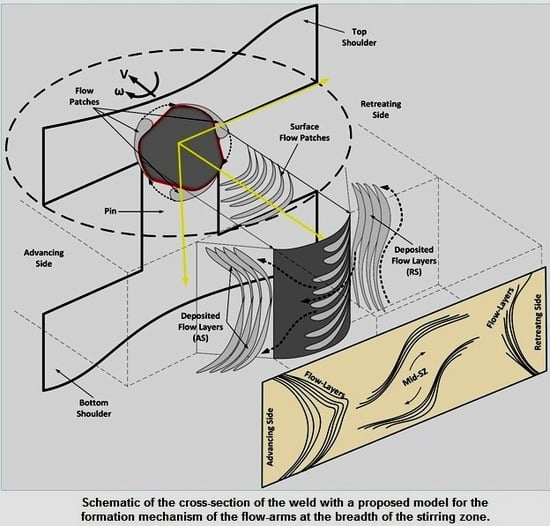
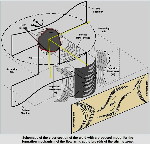
3.5. Building a Model of Internal Flow and Defect Formation

We propose a number of new mechanisms that affect flow, and the formation of defects.

3.5.1. Proposed Composition of Flow Layers

The metallurgical analysis in Figure 8 and Figure 9 shows that the flow line patterns evident in optical microscopy are in fact oxidation effects in the AS, and the accumulation of the shearing and formation of high-density sub-grain boundaries during the DRX procedure in the RS. Thus, we propose that what are conventionally called flow arms are better understood as ‘flow layers’.
We believe the more accurate interpretation, for the AS, is that they represent the oxidised fronts between packets of material that have been transported through the weld by tool motion and rotation. Where they occur, they are evident in all cross sections along the weld. An oxidization explanation is feasible considering the high temperature of the stirring process, though an explanation is needed for how the air enters the weld - more on this below. We interpret the layers as being a packing (or stacking) mechanism in the AS, i.e., the flow motion is orthogonal to the flow layer in this region. It is interesting to note that the metallographic macro/micrographs showed that the defect-free samples (see Figure 2) do not reveal flow-arms to the same extent.
For the RS the flow layers represent shearing between different layers, i.e., the flow motion may be in/out of the page. This is inferred from by the microstructure in Figure 9, which shows elongated grains with internal accumulation of sub-grain boundaries that have been subject to self-rearrangement during dynamic recrystallization. More specifically, the proposed DRX mechanism is that the stirred flow packets experience severe shearing, and hence stored strain is induced. By using the heat generated during re-cooling, the elongated grains cause a self-rearrangement to relieve the stored strain, leading to a high-density accumulation of sub-grain boundaries inside the grain. As the elongated grains have similar crystallographic orientation, so too the newly formed sub-grain boundaries have similar crystallographic direction. Consequently, both the grain boundaries and sub-grain boundaries etch similarly, and more so than the matrix. The dark colour of these layers under optical microscopy arises from the etching of these sub-grain boundaries with the characteristic darker contrast compared to the matrix.

3.5.2. Proposed Principles of Motion of Flow Layers

In this regard, and based on the metallurgical improvements, the suggested model in Figure 13 provides an explanation for the entering of the air into the weld region and beginning of the oxidation in flow layers. We introduce the concept of a flow patch. This is a chip of material that is excised from the base material, transported around the weld as a lump, and deposited in the wake of the weld as a flattened layer.
As shown in step 1 in Figure 13, the entering of the tool into workpiece initiates the excision of the flow patches on the tool, as chip formation on the flat area of the tool. These flow patches are softened by the heat generated from the friction, and in contact with the air form an oxide surface layer. By the further embedding of the tool into the workpiece, the flow patch is also pushed into the stirring zone between the AS and the RS (step 2). Simultaneously, a volume of the air also enters into the material which is mostly because of the angled geometry of the flat-thread configuration (steps 2 and 3). Air is readily available in the weld due to the shaking and vibration of the tool-substrate. This trapped air forms as an air-pocket at the corners of the flat-thread geometry and intensifies the oxidation layers of the plasticized mass during the stirring (steps 3 and 4). Eventually, the stirred mass is transported to the trailing edge of the tool, where they plough into the RS and are deposited as the flow layers of the weld (step 5). The oxidized surfaces of these flow patches are the flow layers that are observed in the cross section. They are deposited as periodic layers, corresponding to multiple flow patches.
• EXTRACTION AND FRAGMENTATION OF SUBSTRATE
The first step of the stirring action is the fragmentation of the solid grains, from the body of the workpiece. The frictional heat from this grain fragmentation can soften the mass and form the plasticized mass which enters into the stirring zone. Hot material is broken into large fragments by the tool features (threads and flats). These fragments may be partially attached to the weld mass, or they may be completely severed but retained within the confines of the weld. These fragments are evident in the lacerations on the internal weld surfaces at the entry of the weld, and as loose granules that fall out of the weld. The fragments are cut from the workpiece in an arc from the leading edge of the tool, from the advancing to retreating sides. We propose that the fragments are delineated by the flow layers, i.e. the region between any two flow arms represents a fragment of material that once had exposed surfaces in the region of the flow arms.
• TRANSPORT AND FORCED DEPOSITION
The weld mass, including attached and detached fragments, is moved by the rotation of the tool into the trailing edge space behind the tool. The motion is from the RS towards the AS and results in deposition of the material. This deposition process involved squeezing of the weld bulk and the fragments. This involves shear and forging-like processes, whereby the fragments are squashed back together in a plastic process. The shear adds a heating effect which softens the material and facilitates their solid state bonding. As the plasticised mass moves closer towards the AS, so the fragments are flattened and squashed up against the AS—this creates the hourglass border. We propose this is the reason for the increasingly fine spacing between the flow arms closer to the AS compared to the centre of the weld. The final result is thin streaks of flow arms, hence the observed interlaced flow.

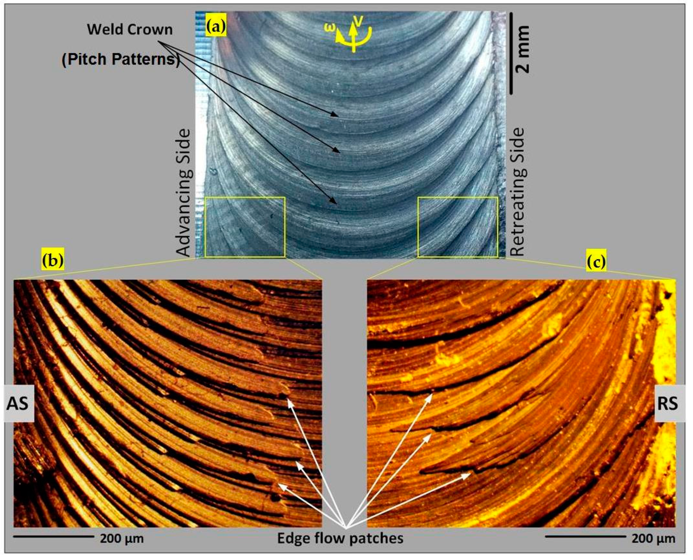
3.5.3. Proposed Principles of Formation of Surface Features

This next explanation addresses the correspondence between internal and surface features. Figure 14 presents a flow model to explain this transport deposition. By revolution of the tool the transportation and deposition of the mass layers happens by the speed ratio (ω/V). The final flow patterns are observable as the flow-arms at the cross-section of the weld, and the related weld pitch patterns at the surface of the weld-line.
In general, the weld pitch patterns at the surface of the weld are directly dependent on the speed ratio between the rotation and advancing actions of the tool, simply as the number of revolution per forward movement, in which can directly influence the formation of the deposited layers at the stirring zone. It should be noted that the pressure imposed underneath the shoulder can affect the shape and size of these bonded layers and compact them together. Also, adding of the new deposited layers into the previous layers leads to increase in compaction condition at the back of the tool.

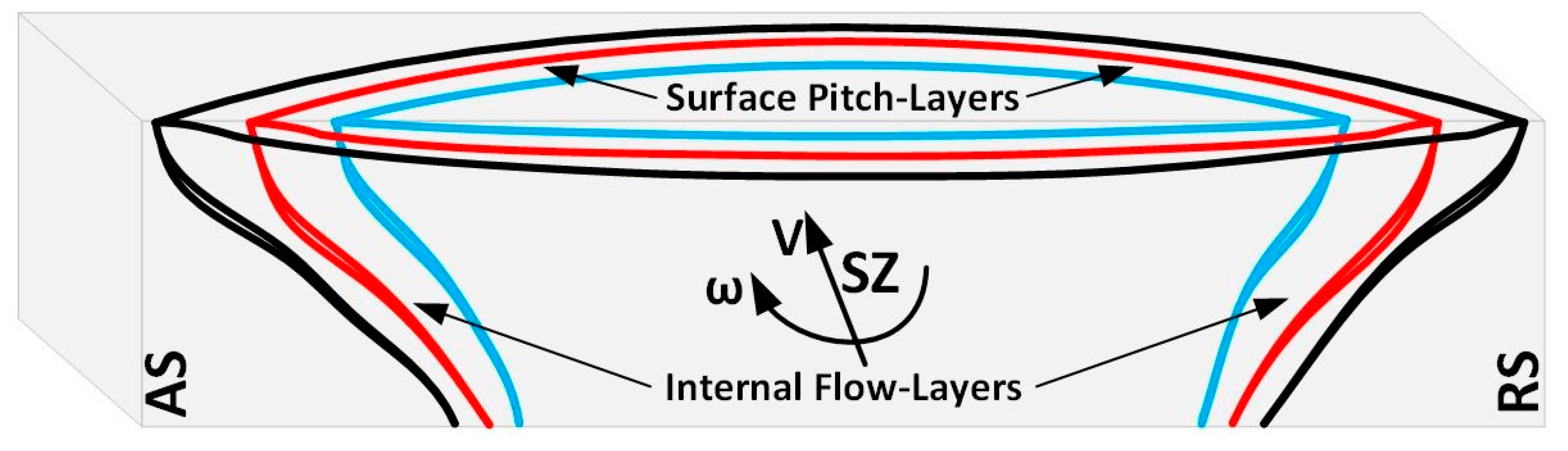
3.5.4. Integrated Weld Transport Model

In Figure 15, the simultaneous formation of the surface flow patches (pitch layers) and the internal flow layers has been demonstrated as a discontinuous flow model for the plasticized batches of the mass which are formed by the revolution of the tool. As the shoulder action is directly responsible for the formation of the surface flow patches at the sub-shoulder region, the rotation and the advancement of the pin at the mid-SZ area generates the plasticized flow batches at the proximity of the tool, at the breadth of AS-RS. The deposited flow layers at the trailing edge of the tool form the bended flow layers at the borders of the AS and RS, which are revealed as the hourglass-boundaries within the cross-section of the weld.

4. Discussion

4.1. Originality

The work makes the following original contributions to the understanding of the welding of AA6082-T6.

4.1.1. Characterization of the Flow Layers at the Hourglass-Borders

The combination of the metallographic delineation in optical microscopy and the metallurgical analysis by the SEM and EDS, confirms that the dark curved patterns in the AS and RS hourglass borders of flow-arms, being oxidation layers (AS) and elongated grains with a high-density of accumulation of the sub-grain boundaries as the result of the shearing and DRX (RS).
The original aim of this work was to understand the relationship between flow regimes and physical defects. The results show that the flow layers are important in understanding the internal flow, and the resulting defects. Failed welds show more flow lines, and show in specific locations in the cross section. Also these flow lines are associated with oxidisation. OM methods are relatively quick and simple to apply, but identification of these characteristics of the flow lines required electron microscopy. Now that the metallurgical nature has been elucidated, it is potentially possible that the simpler OM method could be used in future as an industrial quality control tool.

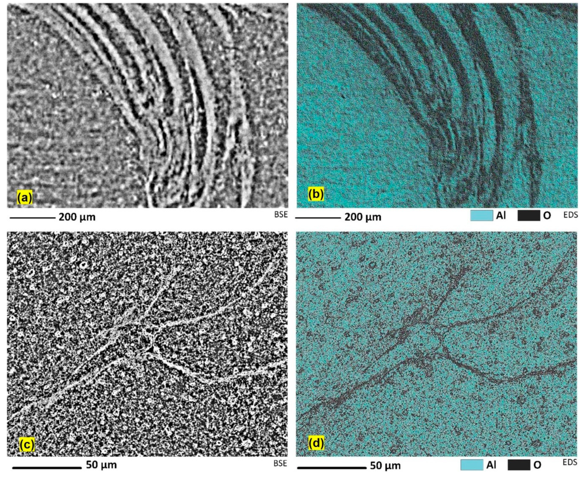
4.1.2. Visualization of Flow Layers

In this work, based on the microscopic observations, we elucidated the internal flow features of the plastic deformation in different regions of the stirring zone during the bobbin friction stir processing. Key concepts that emerge are:
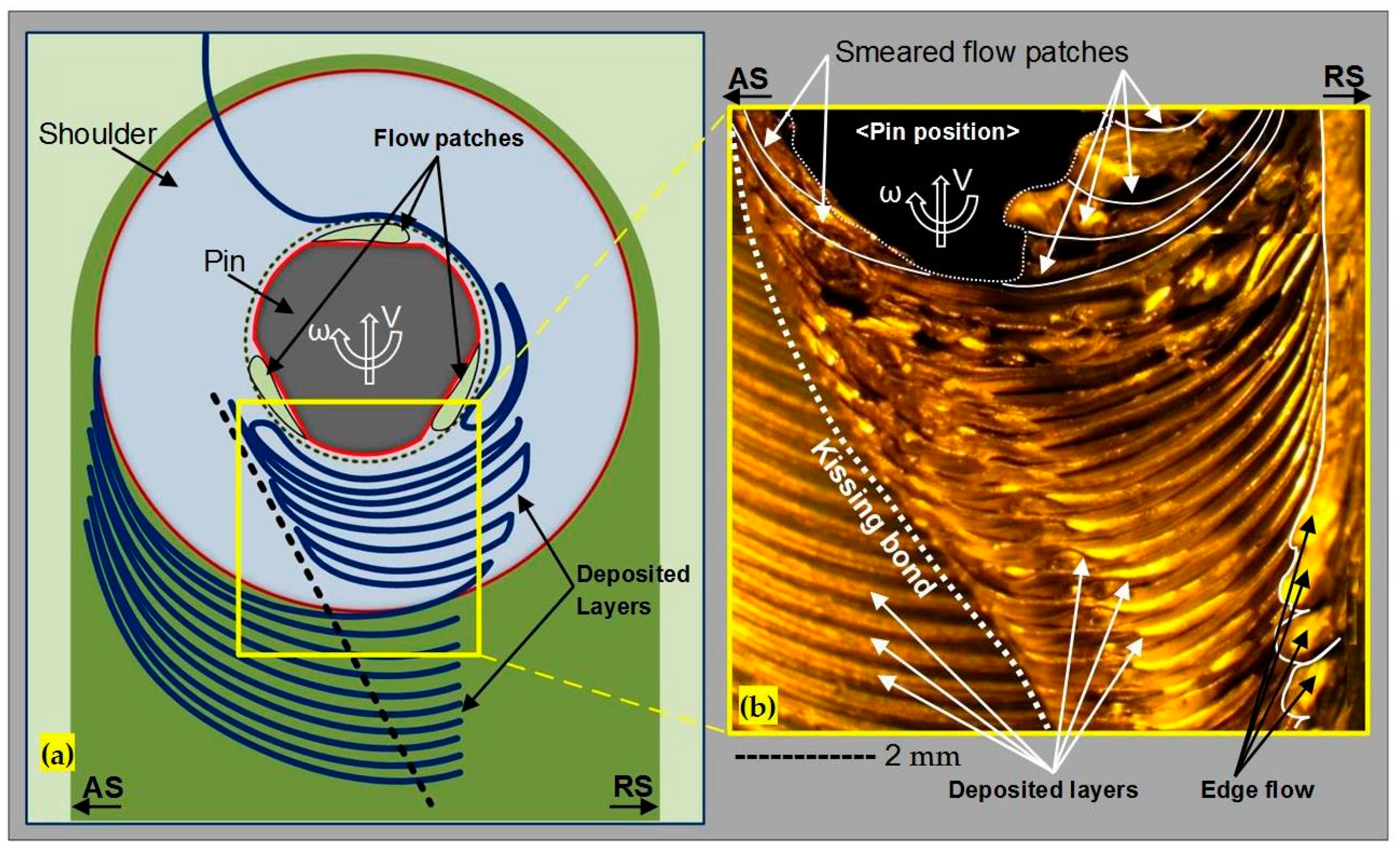
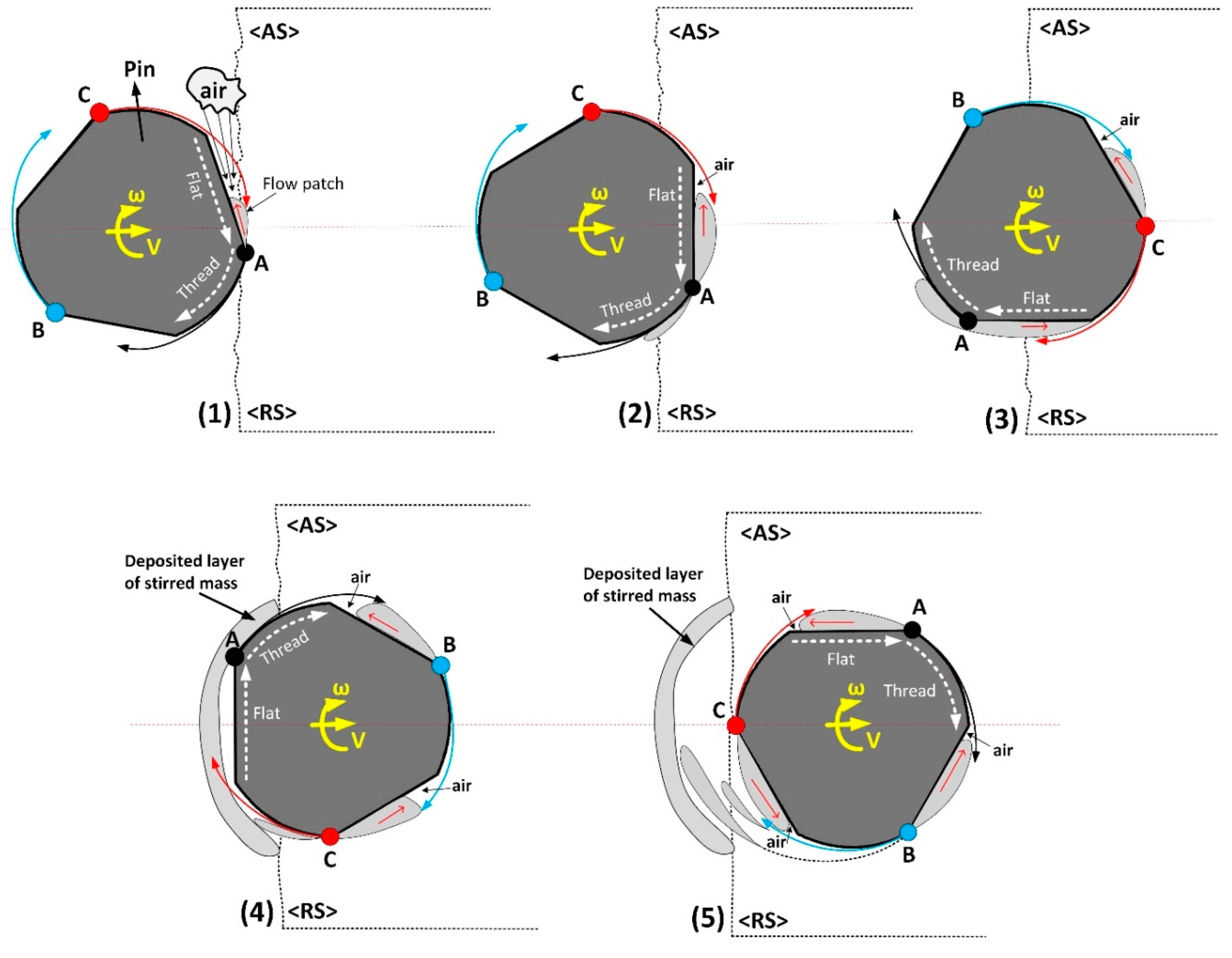
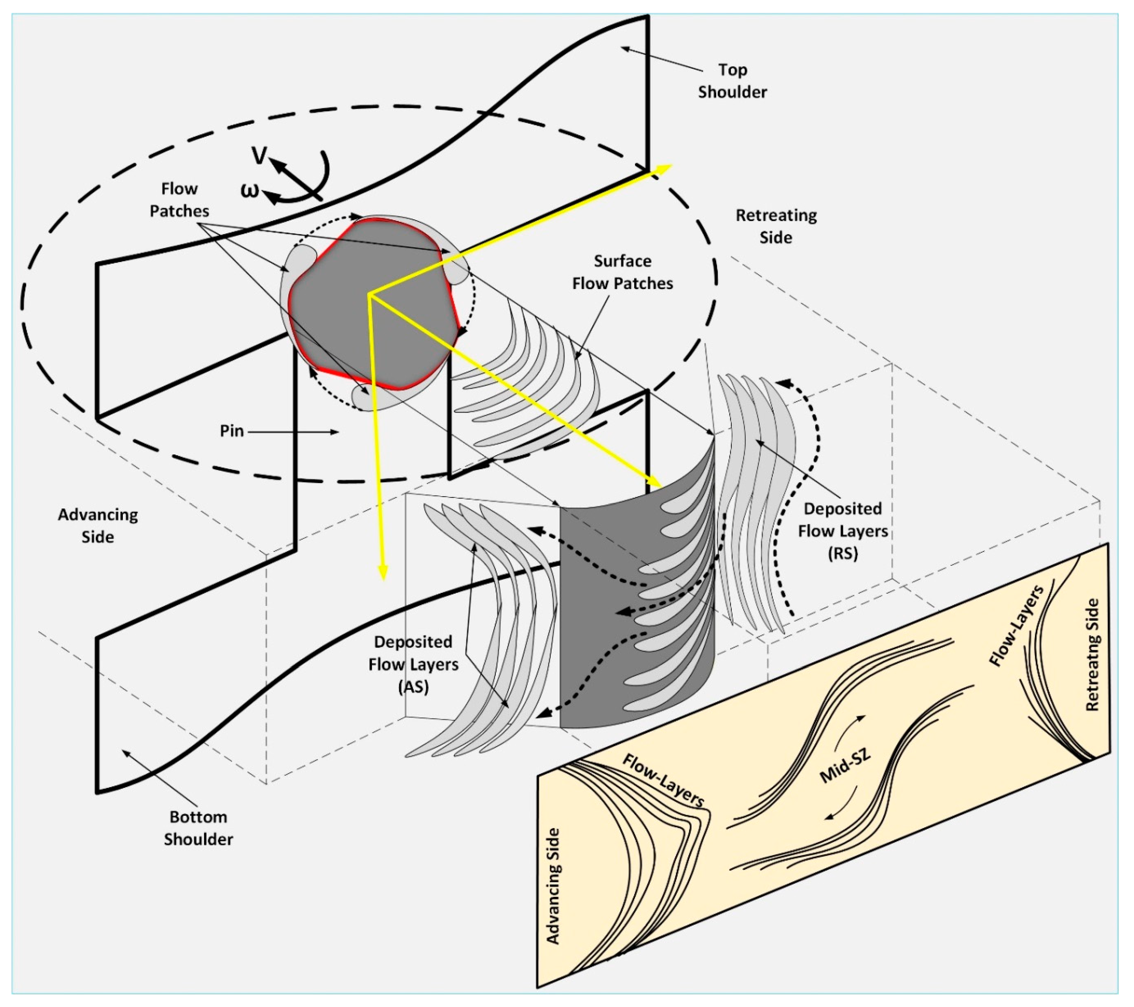
  • Packets of material (‘flow patches’) are transported around the pin.
  • Flow patches are transported round the RS to the back of the tool, where they experience high localized shearing at their mutual boundaries, as evidenced in high density of sub-grain boundaries.
  • Flow patches are transported all the way round the tool to the AS, where they are stacked on each other and flattened in the process. Air enters at or before this stage and causes oxidization of the boundaries, as evidenced in EDS elemental mapping.

4.1.3. Proposing a Model of the Internal Flow Processes

Many other studies have been based on the assumption of continuous flow within the stirring zone. However, such approaches have not had very much success in predicting the actual flow. It has been particularly difficult to model the tunnel void as a flow-based defect using continuous flow assumptions. The present work puts this into context, by finding that the flow is highly discontinuous, based on observation of the microstructure. In turn this has been facilitated by discovery of a suitable reagent and metallographic measurement. Consequently, the present results imply that methods based on continuous flow computational fluid dynamics (CFD) are unlikely to be successful in explaining flow defects. In CFSW the flow lines (“onion rings”) are attributed to the tool-material interaction [18]. However, these flow features are not defects per se. Likewise for BFSW the tool-material interaction has been identified as contributing to discontinuous flow as a bulk effect [34]. The present work is consistent with these findings, but extends them to the defect situation. In particular here it is proposed that the thread-flat features of the pin further to a finer scale discontinuity of flow, in terms of packets of material. These are deposited at the trailing edge of the tool, and squashed in the process.

4.2. Implications for Practitioners

Industry users of AA6082-T6 should note that tunnel defects are associated with internal oxidization of the weld cross section. This has the potential to cause reduced mechanical properties, corrosion resistance and the fatigue strength as the tunnel void as a macro-size discontinuity can deteriorate the integrity-related properties of the weld.

4.3. Limitations of this Work and Implications for Future Research

Our analyses of the flow layers were limited in the number of such layers investigated. We cannot exclude the possibility that flow layers may have features of both oxidization and DRX sub-grain boundary formation. A potential future research project could examine multiple flow layers, at different positions along their length, and evaluate both microstructure (e.g., using SEM or TEM) and elemental composition.
3D visualization of the flow layers was not possible during optical and electron microscopy. A possible research question could be to progressively re-polish the surface in a controlled manner to build up a 3D representation of the flow layers.
Another possible future line of research could be measurement of the mechanical properties of the weld in correlation with the flow features. Progressive loading of a sample of the cross section, with microscopy inspection in between, could identify the evolution of the crack propagation and failure mechanisms. Regarding the oxide layers, it may be useful to apply fractography or creep-fatigue tests to examine crack propagation.
It is to be expected that the formation of the macro-size tunnel void and the micro-cracks during stirring action would extensively affect the strength of the final weldment. Macroscopic defects are likely to be unacceptable to industry users, and hence preventing these is the first priority. Even if there is no tunnel defect, the internal micro-cracks are likely to cause adverse outcomes in the three-point bending and other tests used. Hence there could be value in further research into welding process settings, including tool features, that minimise these defects.

5. Conclusions

The internal flow features of the AA6082-T6 BFSW were evaluated using a set of developed reagents and optical microscopy. The key findings are that the dark curved patterns (conventionally called “flow-arms”), are actually oxidation layers at the advancing side, and at the retreating side are elongated grains with a high-density of accumulation of sub-grain boundaries due to DRX. A model of discontinuous flow within the weld is proposed, based on the microscopic observations. It is inferred that the internal flow is characterized by packets of material (“flow patches”) being transported around the pin. At the RS they experience high localized shearing at their mutual boundaries, as evidenced in high density of sub-grain boundaries. Flow patches at the AS are stacked on each other and exposed to oxidization.

Author Contributions

Conceptualization, A.T., D.J.P.; methodology and formal analysis, A.T.; supervision, D.J.P., D.C., K.S.; validation, A.T., D.J.P.; writing–original draft, A.T.; writing–review & editing, A.T., D.J.P., D.C., K.S.

Funding

This research received no external funding.

Acknowledgments

Thanks are extended to Mike Flaws and Kevin Stobbs for assistance with electron and optical microscopy, respectively.

Conflicts of Interest

The authors declare no conflict of interest.

References

  1. Thomas, W. Friction Stir Welding. International Patent Application No. PCT/GB92/02203, 6 December 1991. [Google Scholar]
  2. Thomas, W.; Wiesner, C.; Marks, D.; Staines, D. Conventional and bobbin friction stir welding of 12% chromium alloy steel using composite refractory tool materials. Sci. Technol. Weld. Join. 2009, 14, 247–253. [Google Scholar] [CrossRef]
  3. Threadgill, P.L.; Ahmed, M.; Martin, J.P.; Perrett, J.G.; Wynne, B.P. The use of bobbin tools for friction stir welding of aluminium alloys. Mater. Sci. Forum 2010, 638, 1179–1184. [Google Scholar] [CrossRef]
  4. Thomas, W.; Wiesner, C. Recent developments of FSW technologies: Evaluation of root defects, composite refractory tools for steel joining and one-pass welding of thick sections using self-reacting bobbin tools. In Trends in Welding Research, Proceedings of the 8th International Conference, Pine Mountain, GA, USA, 1–6 June 2008; ASM International: Novelty, OH, USA, 2009; p. 25. [Google Scholar]
  5. Thomas, W.; Nicholas, E. Friction stir welding for the transportation industries. Mater. Des. 1997, 18, 269–273. [Google Scholar] [CrossRef]
  6. Svensson, L.E.; Karlsson, L.; Larsson, H.; Karlsson, B.; Fazzini, M.; Karlsson, J. Microstructure and mechanical properties of friction stir welded aluminium alloys with special reference to AA 5083 and AA 6082. Sci. Technol. Weld. Join. 2000, 5, 285–296. [Google Scholar] [CrossRef]
  7. Russell, M.; Shercliff, H. Analytical modelling of microstructure development in friction stir welding. In Proceedings of the 1st International Symposium On Friction Stir Welding, Thousand Oaks, CA, USA, 14–16 June 1999. [Google Scholar]
  8. Sued, M.; Tamadon, A.; Pons, D. Material flow visualization in bobbin friction stir welding by analogue model. Proc. Mech. Eng. Res. Day 2017, 2017, 368–369. [Google Scholar]
  9. Waldron, D.J.; Roberts, R.W.; Dawes, C.J.; Tubby, P.J. Friction Stir Welding—A Revolutionary New Joining Method. J. Aerosp. 1998, 107, 1247–1252. [Google Scholar]
  10. Xu, H.; Tang, H.; Liu, Z.; Xie, M.; Jiao, J. Microstructure and Mechanical Properties of 6082 Aluminum Alloy Joints Welded by MIG. Hot Work. Technol. 2010, 1, 42. [Google Scholar]
  11. Zhang, H.; Wang, M.; Zhang, X.; Yang, G. Microstructural characteristics and mechanical properties of bobbin tool friction stir welded 2A14-T6 aluminum alloy. Mater. Des. 2015, 65, 559–566. [Google Scholar] [CrossRef]
  12. Martin, J.; Wei, S. Friction Stir Welding Technology for Marine Applications. In Friction Stir Welding and Processing VIII; Springer: Berlin/Heidelberg, Germany, 2015; pp. 219–226. [Google Scholar]
  13. Esmaily, M.; Mortazavi, N.; Osikowicz, W.; Hindsefelt, H.; Svensson, J.; Halvarsson, M.; Martin, J.; Johansson, L. Bobbin and conventional friction stir welding of thick extruded AA6005-T6 profiles. Mater. Des. 2016, 108, 114–125. [Google Scholar] [CrossRef]
  14. Chen, C.; Kovacevic, R. Thermomechanical modelling and force analysis of friction stir welding by the finite element method. Proc. Inst. Mech. Eng. Part C J. Mech. Eng. Sci. 2004, 218, 509–519. [Google Scholar] [CrossRef]
  15. Chen, Z.; Pasang, T.; Qi, Y. Shear flow and formation of Nugget zone during friction stir welding of aluminium alloy 5083-O. Mater. Sci. Eng. A 2008, 474, 312–316. [Google Scholar] [CrossRef]
  16. Gopi, S.; Manonmani, K. Microstructure and mechanical properties of friction stir welded 6082-T6 aluminium alloy. Aust. J. Mech. Eng. 2013, 11, 131–138. [Google Scholar] [CrossRef]
  17. Sued, M.; Pons, D.; Lavroff, J.; Wong, E.H. Design features for bobbin friction stir welding tools: Development of a conceptual model linking the underlying physics to the production process. Mater. Des. 2014, 54, 632–643. [Google Scholar] [CrossRef]
  18. Krishnan, K. On the formation of onion rings in friction stir welds. Mater. Sci. Eng. A 2002, 327, 246–251. [Google Scholar] [CrossRef]
  19. Liechty, B.; Webb, B. Modeling the frictional boundary condition in friction stir welding. Int. J. Mach. Tools Manuf. 2008, 48, 1474–1485. [Google Scholar] [CrossRef]
  20. Tamadon, A.; Pons, D.; Sued, M.; Clucas, D.; Wong, E. Analogue Modelling of Bobbin Tool Friction Stir Welding. In Proceedings of the International Conference on Innovative Design and Manufacturing, Auckland, New Zealand, 24–26 January 2016. [Google Scholar]
  21. Tamadon, A.; Pons, D.J.; Sued, K.; Clucas, D. Development of Metallographic Etchants for the Microstructure Evolution of A6082-T6 BFSW Welds. Metals 2017, 7, 423. [Google Scholar] [CrossRef]
  22. Prangnell, P.; Heason, C. Grain structure formation during friction stir welding observed by the ‘stop action technique’. Acta Mater. 2005, 53, 3179–3192. [Google Scholar] [CrossRef]
  23. Fonda, R.; Knipling, K.; Bingert, J. Microstructural evolution ahead of the tool in aluminum friction stir welds. Scr. Mater. 2008, 58, 343–348. [Google Scholar] [CrossRef]
  24. Fonda, R.; Reynolds, A.; Feng, C.; Knipling, K.; Rowenhorst, D. Material flow in friction stir welds. Metall. Mater. Trans. A 2013, 44, 337–344. [Google Scholar] [CrossRef]
  25. Coelho, R.S.; Kostka, A.; Dos Santos, J.; Pyzalla, A.R. EBSD Technique Visualization of Material Flow in Aluminum to Steel Friction-stir Dissimilar Welding. Adv. Eng. Mater. 2008, 10, 1127–1133. [Google Scholar] [CrossRef]
  26. Hilgert, J.; Schmidt, H.; Dos Santos, J.; Huber, N. Thermal models for bobbin tool friction stir welding. J. Mater. Process. Technol. 2011, 211, 197–204. [Google Scholar] [CrossRef]
  27. Hilgert, J.; Hütsch, L.L.; dos Santos, J.; Huber, N. Material flow around a bobbin tool for friction stir welding. In Proceedings of the COMSOL Conference, Paris, France, 17–19 November 2010. [Google Scholar]
  28. Hilgert, J.; Dos Santos, J.; Huber, N. Shear layer modelling for bobbin tool friction stir welding. Sci. Technol. Weld. Join. 2012, 17, 454–459. [Google Scholar] [CrossRef]
  29. Davis, J.R. Aluminum and Aluminum Alloys; ASM International: Novelty, OH, USA, 1993. [Google Scholar]
  30. Sued, M.K. Fixed Bobbin Friction Stir Welding of Marine Grade Aluminium. Ph.D. Thesis, University of Canterbury, Christchurch, New Zealand, 2015. [Google Scholar]
  31. Tamadon, A.; Pons, D.J.; Sued, K.; Clucas, D. Formation Mechanisms for Entry and Exit Defects in Bobbin Friction Stir Welding. Metals 2018, 8, 33. [Google Scholar] [CrossRef]
  32. DS, K.C.; Tamadon, A.; Pons, D.; Sued, M.; Clucas, D.; Wong, E. Preparation of Plasticine Material for Analogue Modelling. In Proceedings of the International Conference on Innovative Design and Manufacturing (ICIDM 2016), Auckland, New Zealand, 24–26 January 2016. [Google Scholar]
  33. Tamadon, A.; Pons, D.; Sued, K.; Clucas, D. Thermomechanical grain refinement in AA6082-T6 thin plates under Bobbin friction stir welding. Metals 2018, 8, 375. [Google Scholar] [CrossRef]
  34. Sued, M.K.; Pons, D.J. Dynamic Interaction between Machine, Tool, and Substrate in Bobbin Friction Stir Welding. Int. J. Manuf. Eng. 2016, 1–14. [Google Scholar] [CrossRef]
Figure 1. Schematic of the BFSW process for a butt-joint position.
Metals 09 01059 g001
Figure 2. Macrostructure of the cross-section of the BFSW joint for two different welding speeds (etched by reagent A), (a) (w = 400 rpm, 350 mm/min), and (b) (w = 650 rpm, 400 mm/min). Arrows show proposed internal flows. Dashed white lines show the SZ borders. (1) weld crown, (2) tunnel void, (3) AS border, and (3) RS border.
Metals 09 01059 g002
Figure 3. Photomontage of the microscopic features for the BFSW weld structure, near the AS and RS borders (etched by Reagent B). (a) transition region in AS border (regions 3 in Figure 2b), (b) transition region in RS border (regions 4 in Figure 2b).
Metals 09 01059 g003
Figure 4. Photomontage microfeatures of the BFSW weld at the transverse cross-section (revealed by Reagent C). (a) AS border, (b) RS border. (1) flow-arms, (2) tunnel void, (3) finger patterns, and (4) kissing bond.
Metals 09 01059 g004
Figure 5. Micrograph of the tunnel void and the microflow features around the defect at the circumferential side of the tunnel void (revealed by Reagent C). (a) Cascade flow bands, (b) hook lines, (c) finger pattern, (d) swirling lines.
Metals 09 01059 g005
Figure 6. Interlaced flow patterns at the AS border of SZ as the following of the cascade microflow (Reagent C).
Metals 09 01059 g006
Figure 7. Microflows, tangled in different region of the cascade flow region of the SZ (Reagent C). (a) swirling line (region d in Figure 5), (b) higher magnification of (a); hair-line micro-crack, (c) magnified finger pattern and the wavy flow lines (region c in Figure 5), and (d) hook line flow at the jagged edge of the tunnel void (region b in Figure 5).
Metals 09 01059 g007
Figure 8. Analysis of the flow-arms region (region 1, Figure 4a) using (a) BSE, and (b) EDS elemental map, and similarly for (c,d) hair-line micro-crack position (demonstrated in Figure 7b). The oxygen-rich areas of the EDS elemental map have been delineated in dark (b,d).
Metals 09 01059 g008
Figure 9. SEM analysis of the flow arm shaped branches at the RS. (a) A bunch of elongated grains at the position of the flow pattern, (b) higher magnification of the inside of the grain, representative of the high density of the sub-grain boundaries as a response to the stored strained during the DRX.
Metals 09 01059 g009
Figure 10. Grain and flow details of the sub-shoulder region of the weld crown (Reagent B). (a) macrograph of the sub-shoulder region; different microscopic features are enlarged as Regions A, B, C in Figure 10b–d, respectively; (b) Regions A; coarse grain structure, (c) Regions B; elongated grains, (d) Regions C; ultrafine grained microstructure.
Metals 09 01059 g010
Figure 11. Surface flow patterns at the centre of the weld-line. (a) Plan view of the weld surface, (b) Macro-etched sub-shoulder (0.5 mm deep) flow patterns at the AS, and (c) Macro-etched sub-shoulder (0.5 mm deep) flow patterns at the RS.
Metals 09 01059 g011
Figure 12. The top view of the sub-shoulder region with a proposed model for the flow-lines 0.5 mm underneath the shoulder during the stirring action. (a) the flow model of the sub-shoulder area, (b) the macro-etched sub-shoulder region including the actual flow patterns, at the position of the exit zone.
Metals 09 01059 g012
Figure 13. Schematic of the entering of the tool into the workpiece, with a proposed model for the entering of the air into the weld region and formation of the oxidation layer between the deposited mass layers at the trailing edge of the tool (Steps 15 explain the details of the discontinuous flow mechanism).
Metals 09 01059 g013
Figure 14. The proposed flow patterns for the flow-arms and the weld pitch patterns at the cross-section and surface of the weld region, respectively. The model aims to reveal the flow lines during the revolution of the tool and deposition of the layered mass at the trailing edge of the tool.
Metals 09 01059 g014
Figure 15. Schematic of the cross-section of the weld with a proposed model for the formation mechanism of the flow-arms at the breadth of the stirring zone, between the AS and RS.
Metals 09 01059 g015
Table 1. Element composition of the AA6082-T6 aluminium alloy (wt %). Data from [29].
AA6082-T6 Aluminium Alloy
Chemical Element% Present
Silicon (Si)(0.70–1.30)
Magnesium (Mg)(0.60–1.20)
Manganese (Mn)(0.40–1.00)
Iron (Fe)(0.0–0.50)
Chromium (Cr)(0.0–0.25)
Zinc (Zn)(0.0–0.20)
Titanium (Ti)(0.0–0.10)
Copper (Cu)(0.0–0.10)
Other (Each)(0.0–0.05)
Other (total)(0.0–0.15)
Aluminium (Al)Balance
Table 2. Parameters of the BFSW process for the AA6082-T6 weld trials.
Work Temp (°C)DShoulder (mm)DPin (mm)DShoulder/DPinPlate Thickness (mm)Compression RatioFeed ω (rpm)Speed V (mm/min)Thread Pitch (mm)Number of Threads
18 °C217363.75%4003501.25
650400
Table 3. Different reagent compositions with separate sequences of processing.
Name of EtchantEtchant Composition
A2.5 mL HF + 2.5 mL HCl + 95 mL H2O (30 s, 50 °C), then: 15 mL H3PO4 + 85 mL H2O (30 s, 70 °C)
B0.5 g (NH4)2MoO4 + 3.0 g NH4Cl + 1 mL HF + 18 mL HNO3 + 80 mL H2O (90 s, 70 °C)
C10 g CrO3 + 2 g Na2SO4 + 10 mL HNO3 + 10 mL CH3COOH + 1 mL HF + 80 mL H2O (60 s, 70 °C)

