
Welding Distortion Prediction in 5A06 Aluminum Alloy Complex Structure via Inherent Strain Method

Abstract
:
1. Introduction
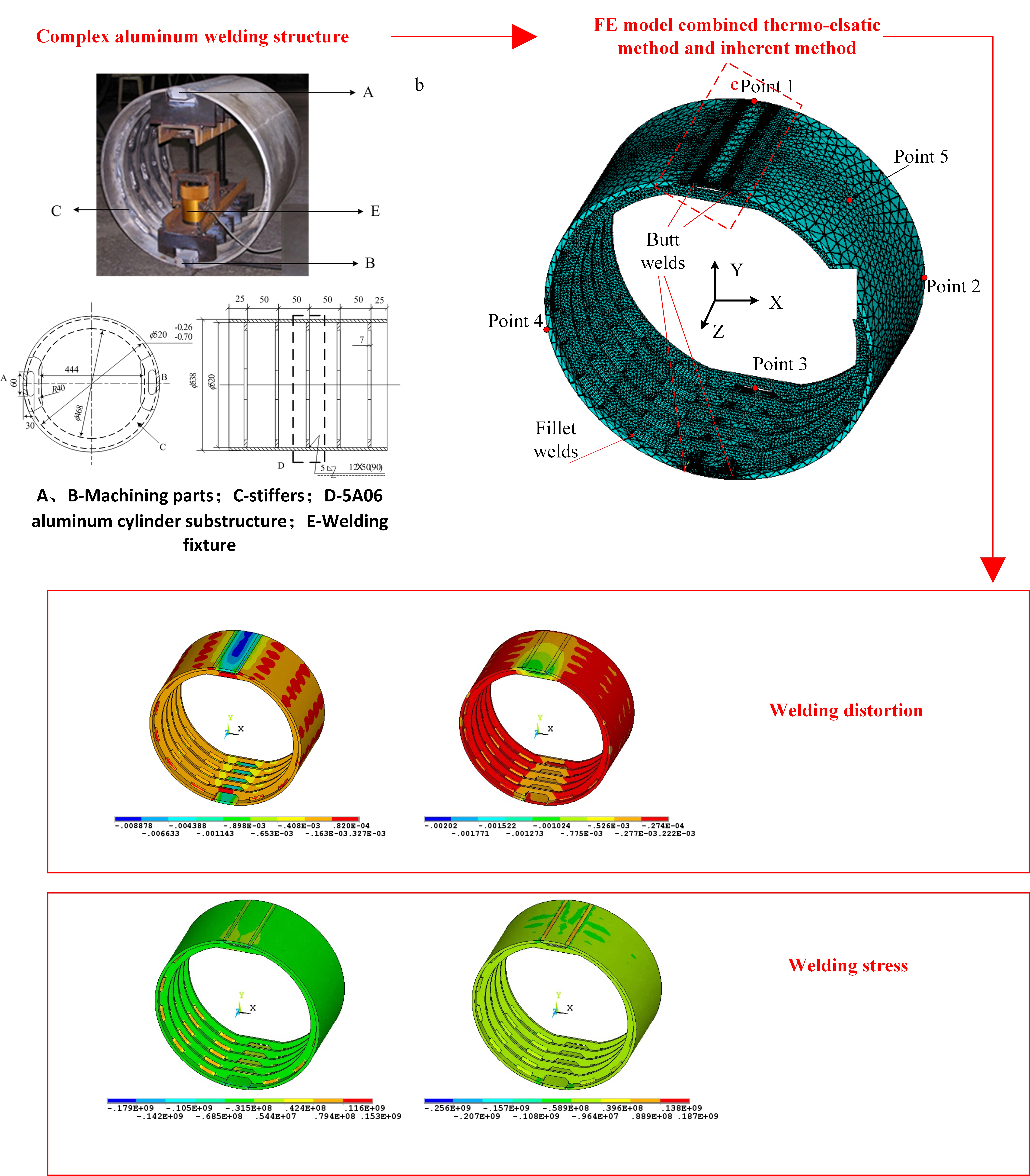
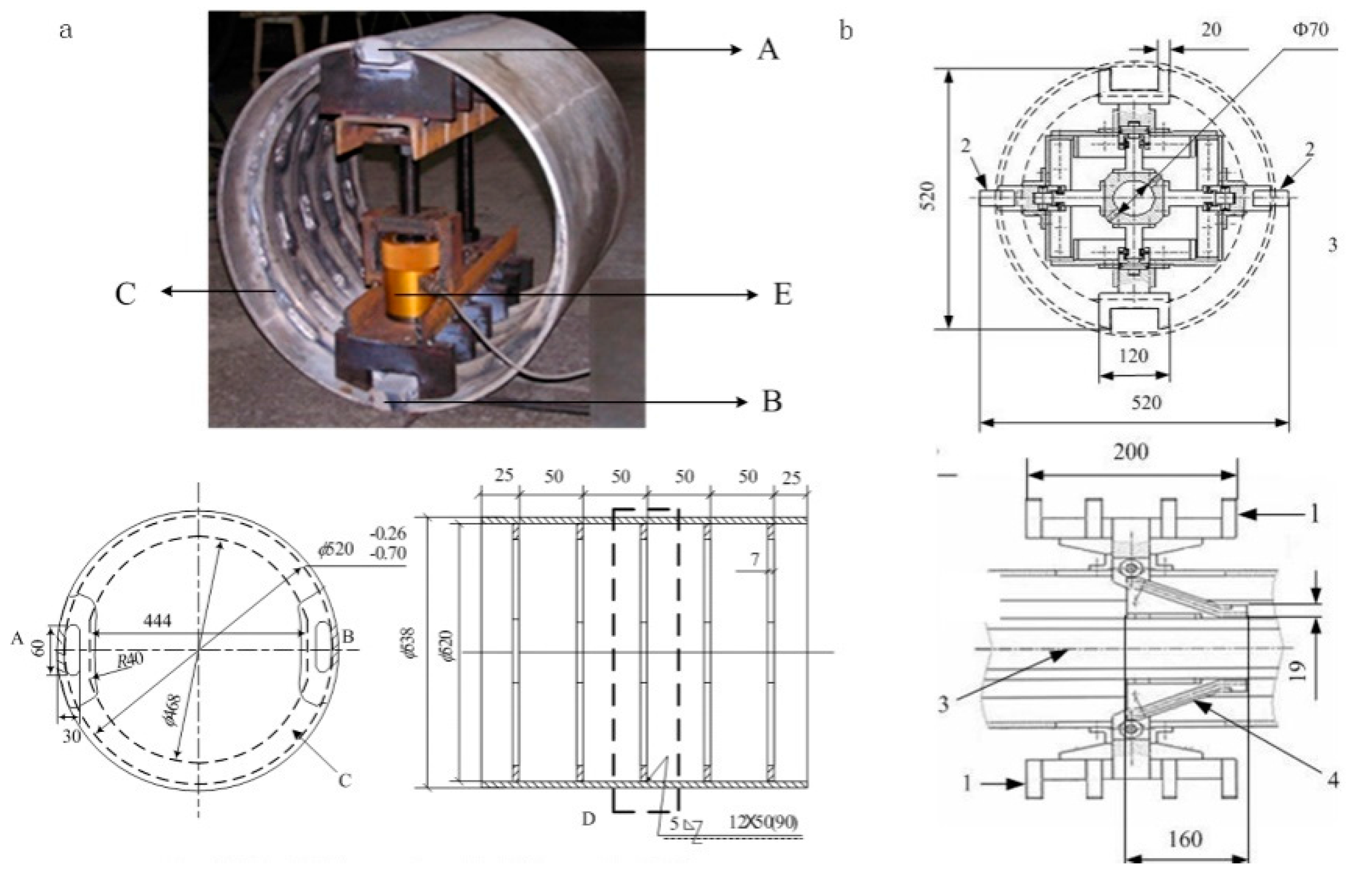
2. Model Analysis
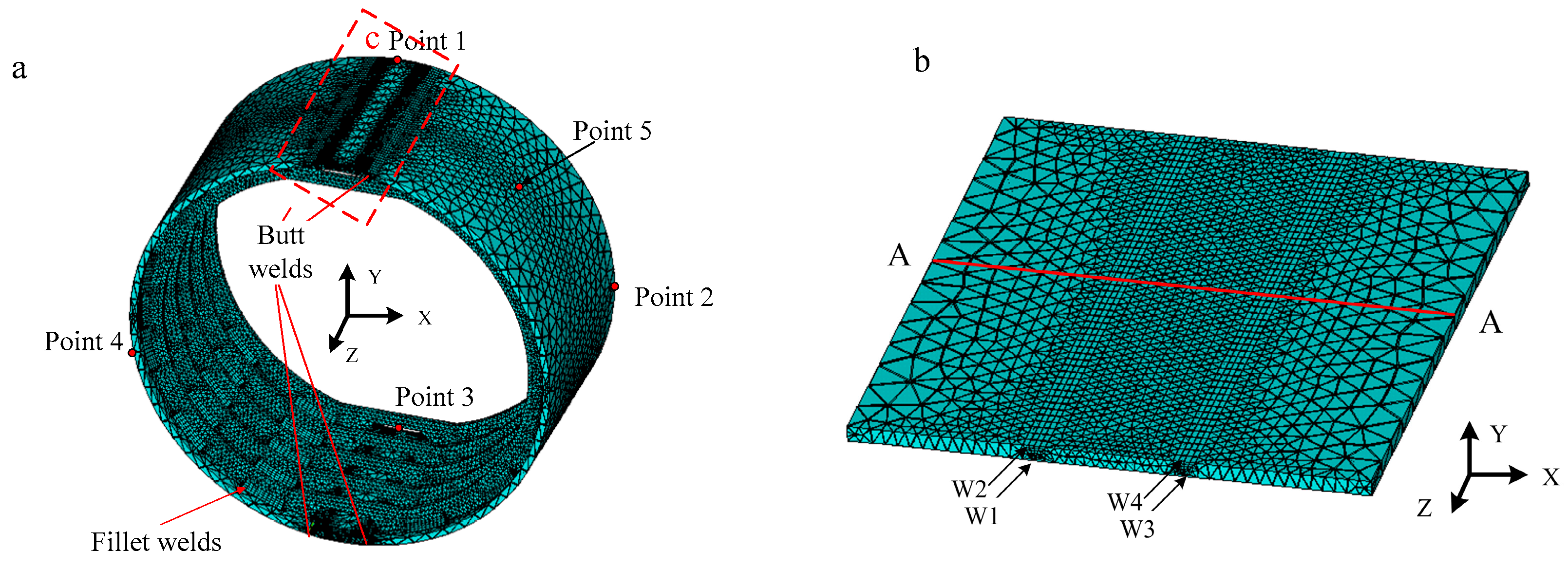
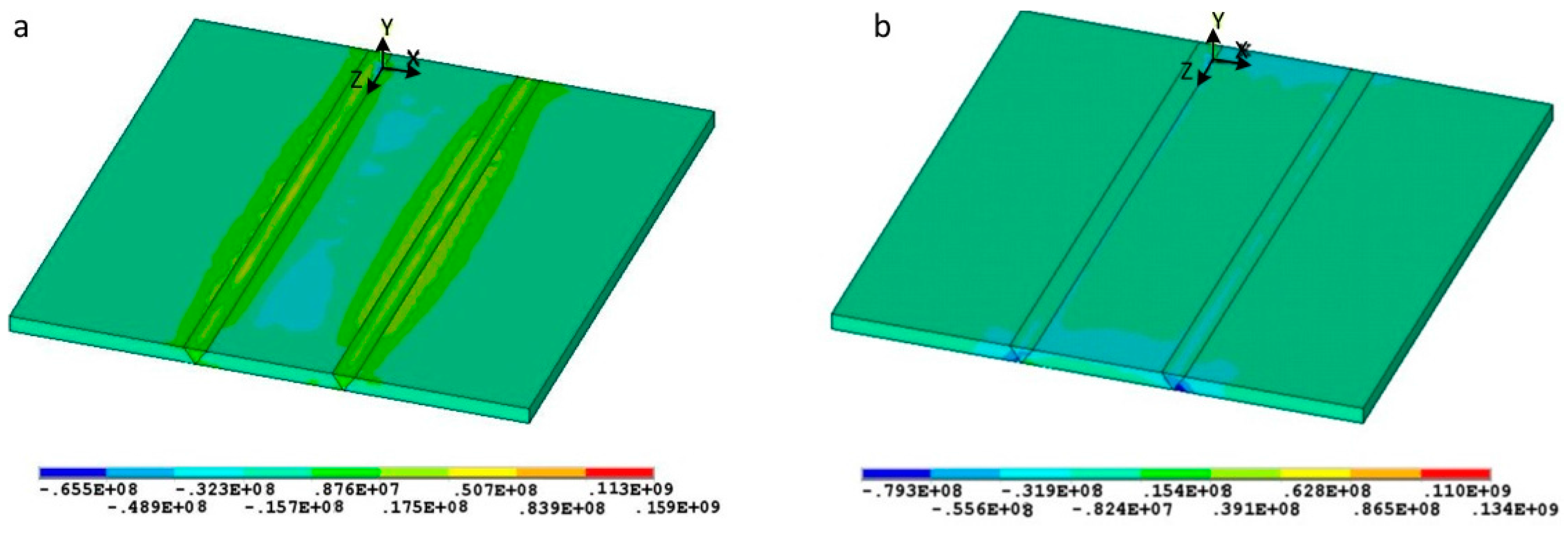
3. Welding Distortion Prediction in Thin Plate Fabrication by Means of Inherent Strain FE Method
4. Results and Discussion
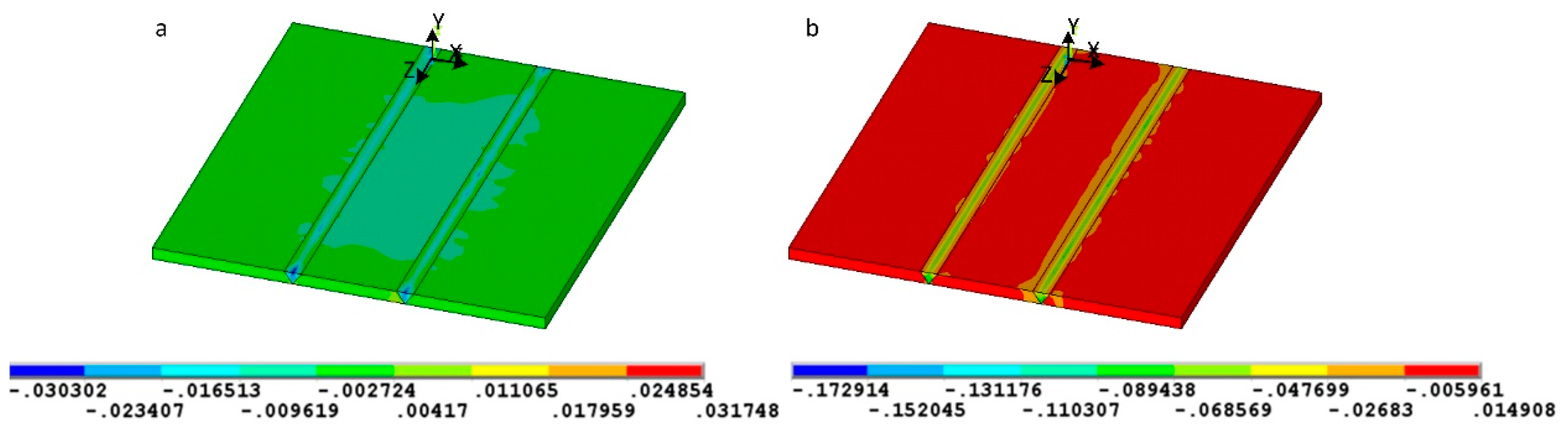
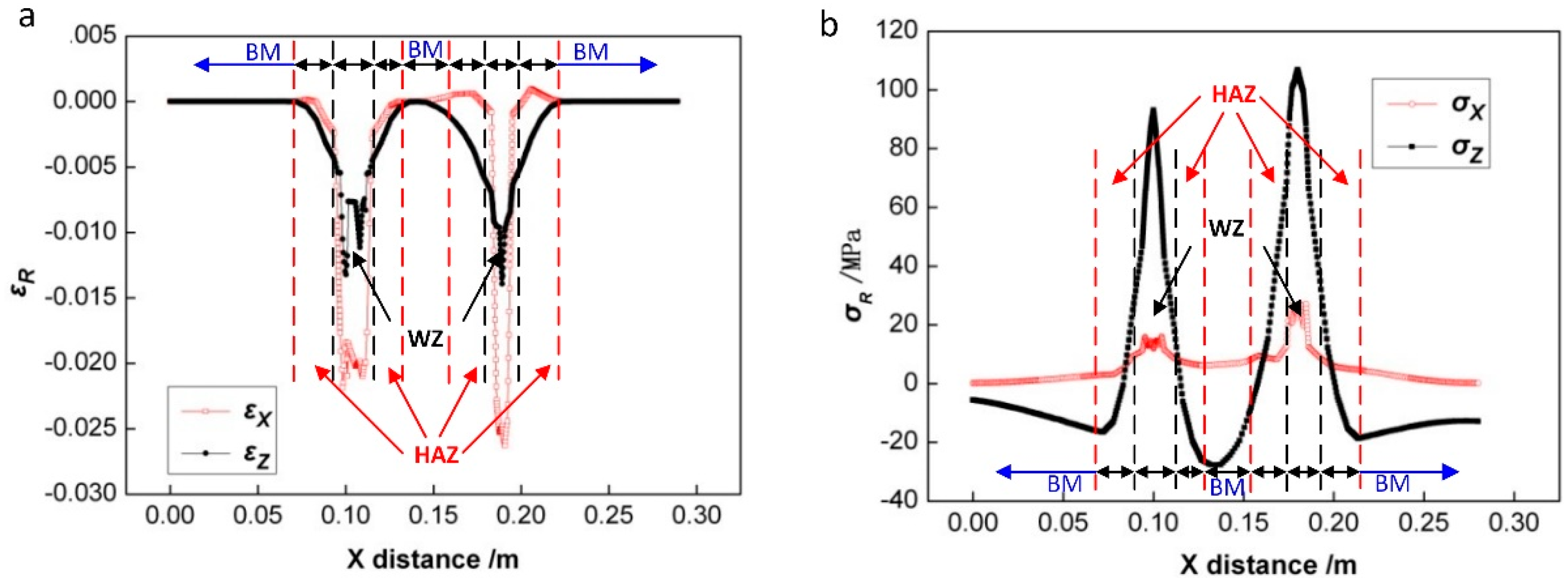
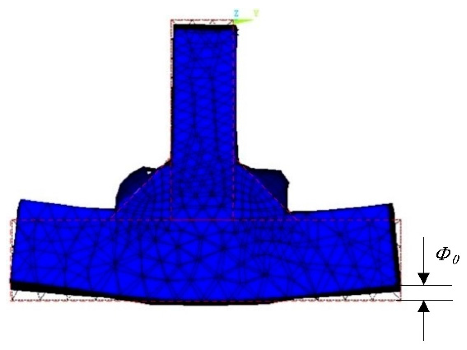
4.1. Inherent Strain Analysis of Butt Weld and Fillet Welds
4.2. Analysis of the Aluminum Alloy Structure
4.3. Buckling Deformation Analysis
5. Conclusions
Acknowledgments
Author Contributions
Conflicts of Interest
References
- Masubuchi, K.; Bryan, J.J.; Muraki, T. Analysis of thermal stresses and metal movement during welding. ASME J. Eng. Mater. Technol. 1975, 97, 81–91. [Google Scholar]
- Zhang, H.; Wang, M.; Zhang, X.; Zhu, Z.; Yu, T.; Yang, G. Effect of welding speed on defect features and mechanical performance of friction stir lap welded 7B04 aluminum alloy. Metals 2016, 6, 87. [Google Scholar] [CrossRef]
- Subramanian, J.; Seetharaman, S.; Gupta, M. Processing and properties of aluminum and magnesium based composites containing amorphous reinforcement: A review. Metals 2015, 5, 743–762. [Google Scholar] [CrossRef]
- Zeng, Z.; Li, X.B.; Miao, Y.G.; Wu, G.; Zhao, Z.J. Numerical and experiment analysis of residual stress on magnesium alloy and steel butt joint by hybrid laser-TIG welding. Comput. Mater. Sci. 2011, 50, 1763–1769. [Google Scholar] [CrossRef]
- Zhao, Y.B.; Lei, Z.L.; Chen, Y.B.; Tao, W. A comparative study of laser-arc double-sided welding and double-sided arc welding of 6 mm 5A06 aluminium alloy. Mater. Des. 2011, 32, 2165–2171. [Google Scholar] [CrossRef]
- Carlone, P.; Citarella, R.; Lepore, M.; Palazzo, G.S. A FEM-DBEM investigation of the influence of process parameters on crack growth in aluminum friction stir welded butt joints. Int. J. Mater. Form. 2015, 8, 591–599. [Google Scholar] [CrossRef]
- Jiang, W.; Fan, Q.; Gong, J. Optimization of welding joint between tower and bottom flange based on residual stress considerations in a wind turbine. Energy 2010, 35, 461–467. [Google Scholar] [CrossRef]
- Kuo, H.C.; Wu, L.J. Prediction of deformation to thin ship panels for different heat sources. J. Ship Prod. 2001, 17, 52–61. [Google Scholar]
- Da Nóbrega, J.A.; Diniz, D.S.; Silva, A.A.; Maciel, T.M.; Albuquerque, V.H.C.; Tavares, J.M.R.S. Numerical evaluation of temperature field and residual stresses in an API 5L X80 steel welded joint using the finite element method. Metals 2016, 6, 28. [Google Scholar] [CrossRef]
- Zeng, Z.; Wang, L.J.; Du, P.A.; Li, X.B. Determination of welding stress and distortion in discontinuous welding by means of numerical simulation and comparison with experimental measurements. Comput. Mater. Sci. 2010, 49, 535–543. [Google Scholar] [CrossRef]
- Syahroni, N.; Hidayat, M.I.P. 3D Finite Element Simulation of T-Joint Fillet Weld: Effect of Various Welding Sequences on the Residual Stresses and Distortions. In Numerical Simulation—From Theory to Industry; Andriychuk, M., Ed.; InTech: Rijeka, Croatia, 2012. [Google Scholar]
- ESI Group. Available online: http://www.esi-group.com (accessed on 11 August 2016).
- Park, J.U.; An, G.B.; Woo, W.C.; Choi, J.; Ma, N. Residual stress measurement in an extra thick multi-pass weld using initial stress integrated inherent strain method. Mar. Struct. 2014, 39, 424–437. [Google Scholar] [CrossRef]
- Wang, J.; Rashed, S.; Murakawa, H. Mechanism investigation of welding induced buckling using inherent deformation method. Thin Walled Struct. 2014, 80, 103–119. [Google Scholar] [CrossRef]
- Takeda, Y. Prediction of but welding deformation of curved shell plates by inherent strain method. J. Ship Prod. 2002, 18, 99–104. [Google Scholar]
- Murakawa, H.; Deng, D.; Ma, N.; Wang, J. Applications of inherent strain and interface element to simulation of welding deformation in thin plate structures. Comput. Mater. Sci. 2012, 51, 43–52. [Google Scholar] [CrossRef]
- Kim, T.J.; Jang, B.S.; Kang, S.W. Welding deformation analysis based on improved equivalent strain method to cover external constraint during cooling stage. Int. J. Naval Archit. Ocean Eng. 2015, 7, 805–816. [Google Scholar] [CrossRef]
- Fu, G.; Lourenço, M.; Duan, M.; Estefen, S.F. Influence of the welding sequence on residual stress and distortion of fillet welded structures. Mar. Struct. 2016, 46, 30–55. [Google Scholar] [CrossRef]
- Zeng, Z.; Wang, L.J.; Zhang, H. Efficient estimation of thermo physical parameters for LF6 aluminum alloy. Mater. Sci. Technol. 2008, 24, 309–314. [Google Scholar] [CrossRef]
- Zeng, Z.; Wang, L.J.; Wang, Y.; Zhang, H. Numerical and experimental investigation on temperature distribution of the discontinuous welding. Comput. Mater. Sci. 2009, 44, 1153–1162. [Google Scholar] [CrossRef]
- Wang, R.; Zhang, J.; Serizawa, H.; Murakawa, H. Three-dimensional modelling of coupled flow dynamics, heat transfer and residual stress generation in arc welding processes using the mesh-free SPH method. Mater. Des. 2009, 30, 3474–3481. [Google Scholar] [CrossRef]
- Kim, T.J.; Jang, B.S.; Kang, S.W. Welding deformation analysis based on improved equivalent strain method considering the effect of temperature gradients. Int. J. Naval Archit. Ocean Eng. 2015, 7, 157–173. [Google Scholar] [CrossRef]
- Wang, J.; Yuan, H.; Ma, N.; Murakawa, H. Recent research on welding distortion prediction in thin plate fabrication by means of elastic FE computation. Mar. Struct. 2016, 47, 42–59. [Google Scholar] [CrossRef]
- Jung, G.H.; Tsai, C.L. Plasticity-based distortion analysis for fillet welded thin-plate T-joints. Weld. Res. Abroad 2004, 81, 177–187. [Google Scholar]
- Bachorski, A.; Painter, M.J.; Smailes, A.J.; Wahab, M.A. Finite element prediction of distortion during gas metal arc welding using the shrinkage volume approach. J. Mater. Process. Technol. 1999, 92–93, 405–409. [Google Scholar] [CrossRef]
- Von Mirbach, D.; Schluter, A. Influence of measurement point preparation by rough grinding on the residual stress determination using hole drilling method. Mater. Test. 2016, 58, 585–587. [Google Scholar] [CrossRef]
- Yang, Z.R.; Kang, H.; Lee, Y. Experimental study on variations in charpy impact energies of low carbon steel, depending on welding and specimen cutting method. J. Mech. Sci. Technol. 2016, 30, 2019–2028. [Google Scholar] [CrossRef]
- Matesa, B.; Kozuh, Z.; Dunder, M.; Samardzic, I. Determination of clad plates residual stresses by X-ray diffraction method. Teh. Vjesn. Tech. Gaz. 2015, 22, 1533–1538. [Google Scholar]
- AsleZaeem, M.; Nami, M.R.; Kadivar, M.H. Prediction of welding buckling distortion in a thin wall aluminum T joint. Comput. Mater. Sci. 2007, 38, 588–594. [Google Scholar] [CrossRef]


| Strain Load | εxx | εyy | εzz | εxy | εyz | εxz |
|---|---|---|---|---|---|---|
| Φ0 (mm) | 0.212 | 0.087 | 0.021 | 0.448 | −0.015 | −0.018 |


| Welding Parameters | U (V) | I (A) | Welding Speed (cm·min−1) | Wire Feed Rate (cm·min−1) |
|---|---|---|---|---|
| Value | 26.2 | 286 | 50–60 | 15.7–20 |
| Composition | ω (Si) | ω (Cu) | ω (Mg) | ω (Zn) | ω (Mn) | ω (Ti) | ω (Fe) | ω (Al) |
|---|---|---|---|---|---|---|---|---|
| Mass fraction | 0.004 | 0.001 | 0.058–0.068 | 0.002 | 0.005–0.008 | 0.0002–0.001 | 0.004 | balance |
| Materials Properties | Temperature, °C | |||||
|---|---|---|---|---|---|---|
| Name | 20 | 100 | 200 | 500 | 587 | 630 |
| Young’s modulus (GPa) | 70 | 70 | 61 | 41. | 10 | 1 |
| Linear expansion coefficient (10−6·K−1) | 0.93 × 10⁻⁴ | 1.91 | 4.50 | 13.3 | 15.9 | 17.6 |
| Poisson’s ratio | 0.35 | 0.35 | 0.35 | 0.35 | 0.35 | 0.35 |
| Density (kg·m−3) | 2750 | 2730 | 2710 | 2640 | 2630 | 2450 |
| Specific heat (J·kg−1·K−1) | 898 | 951 | 1003 | 1150 | 1195 | 1165 |
| Yield stress (MPa) | 130 | 100 | 54 | 10 | 5 | 5 |
| Weld No. | Location | Joint Type | Cross-Section (mm2) | WX (mm2) | WY (mm2) | εx | εy | εxy |
|---|---|---|---|---|---|---|---|---|
| 1 | Stiffer front | T-joint | 32 | 0.651 | 2.16 | 0.0204 | 0.067 | 0.0319 |
| 2 | Stiffer front | T-joint | 32 | 0.668 | 2.26 | 0.0208 | 0.071 | 0.0361 |
| 3 | Stiffer front | T-joint | 32 | 0.673 | 2.27 | 0.0210 | 0.072 | 0.0475 |
| 4 | Stiffer front | T-joint | 32 | 0.680 | 2.33 | 0.0212 | 0.073 | 0.0526 |
| 5 | Stiffer front | T-joint | 32 | 0.688 | 2.38 | 0.0215 | 0.074 | 0.0655 |
| 6 | Stiffer front | T-joint | 32 | 0.695 | 2.41 | 0.0217 | 0.076 | 0.0734 |
| 7 | Stiffer front | T-joint | 32 | 0.702 | 2.42 | 0.0219 | 0.076 | 0.0752 |
| 8 | Stiffer front | T-joint | 32 | 0.710 | 2.43 | 0.0222 | 0.076 | 0.0808 |
| 9 | Stiffer front | T-joint | 32 | 0.719 | 2.44 | 0.0225 | 0.077 | 0.0851 |
| 10 | Stiffer front | T-joint | 32 | 0.733 | 2.45 | 0.0229 | 0.077 | 0.0862 |
| 11 | Stiffer front | T-joint | 32 | 0.746 | 2.48 | 0.0233 | 0.078 | 0.0877 |
| 12 | Stiffer front | T-joint | 32 | 0.751 | 2.50 | 0.0235 | 0.079 | 0.0890 |
| 13 | Stiffer back | T-joint | 32 | 0.290 | 0.96 | 0.0090 | 0.030 | 0.0165 |
| 14 | Stiffer back | T-joint | 32 | 0.297 | 1.01 | 0.0092 | 0.031 | 0.0187 |
| 15 | Stiffer back | T-joint | 32 | 0.299 | 1.01 | 0.0093 | 0.031 | 0.0247 |
| 16 | Stiffer back | T-joint | 32 | 0.303 | 1.03 | 0.0094 | 0.032 | 0.0273 |
| 17 | Stiffer back | T-joint | 32 | 0.306 | 1.06 | 0.0095 | 0.033 | 0.0340 |
| 18 | Stiffer back | T-joint | 32 | 0.309 | 1.07 | 0.0096 | 0.034 | 0.0388 |
| 19 | Stiffer back | T-joint | 32 | 0.312 | 1.08 | 0.0097 | 0.034 | 0.0391 |
| 20 | Stiffer back | T-joint | 32 | 0.316 | 1.08 | 0.0099 | 0.034 | 0.0420 |
| 21 | Stiffer back | T-joint | 32 | 0.320 | 1.09 | 0.0100 | 0.034 | 0.0442 |
| 22 | Stiffer back | T-joint | 32 | 0.326 | 1.09 | 0.0102 | 0.034 | 0.0448 |
| 23 | Stiffer back | T-joint | 32 | 0.332 | 1.10 | 0.0104 | 0.035 | 0.0456 |
| 24 | Stiffer back | T-joint | 32 | 0.334 | 1.10 | 0.0105 | 0.035 | 0.0463 |
| 25 | W1 (in Figure 1) | butt weld | 18 | 0.729 | 2.67 | 0.0405 | 0.148 | - |
| 26 | W2 (in Figure 1) | butt weld | 40 | 0.756 | 2.75 | 0.0419 | 0.153 | - |
| 27 | W3 (in Figure 1) | butt weld | 18 | 0.960 | 3.11 | 0.0240 | 0.078 | - |
| 28 | W4 (in Figure 1) | butt weld | 40 | 0.934 | 3.01 | 0.0233 | 0.075 | - |
© 2016 by the authors; licensee MDPI, Basel, Switzerland. This article is an open access article distributed under the terms and conditions of the Creative Commons Attribution (CC-BY) license (http://creativecommons.org/licenses/by/4.0/).
Share and Cite
Zeng, Z.; Wu, X.; Yang, M.; Peng, B. Welding Distortion Prediction in 5A06 Aluminum Alloy Complex Structure via Inherent Strain Method. Metals 2016, 6, 214. https://doi.org/10.3390/met6090214
Zeng Z, Wu X, Yang M, Peng B. Welding Distortion Prediction in 5A06 Aluminum Alloy Complex Structure via Inherent Strain Method. Metals. 2016; 6(9):214. https://doi.org/10.3390/met6090214
Chicago/Turabian StyleZeng, Zhi, Xiaoyong Wu, Mao Yang, and Bei Peng. 2016. "Welding Distortion Prediction in 5A06 Aluminum Alloy Complex Structure via Inherent Strain Method" Metals 6, no. 9: 214. https://doi.org/10.3390/met6090214