
Investigation on a Novel Laser Impact Spot Welding

 ,
,
Abstract
:
1. Introduction
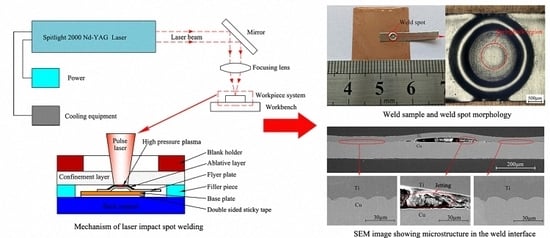
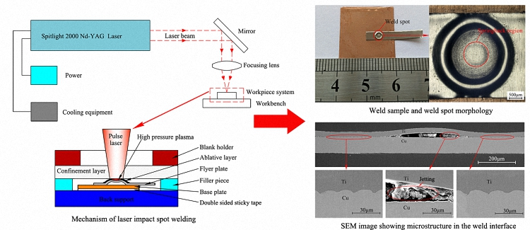
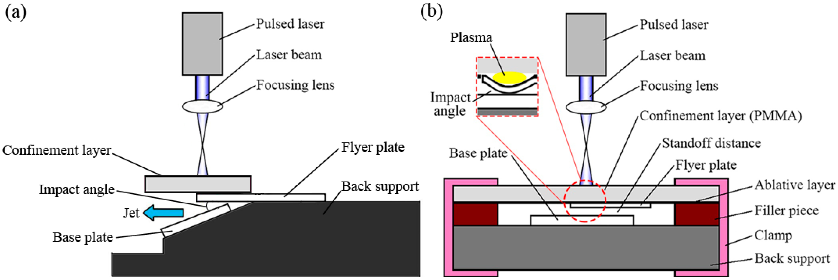
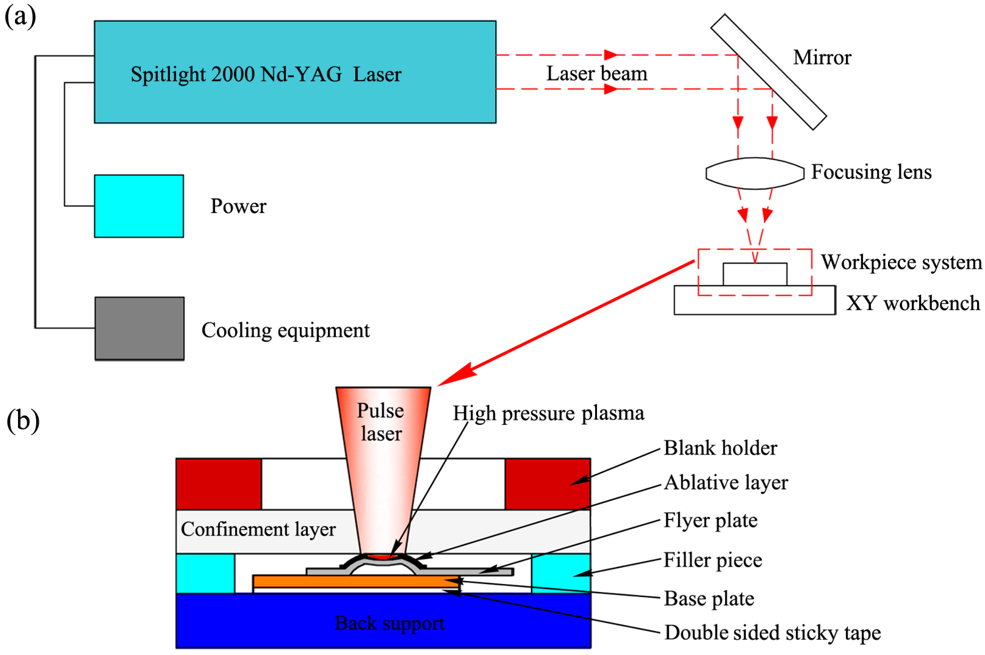
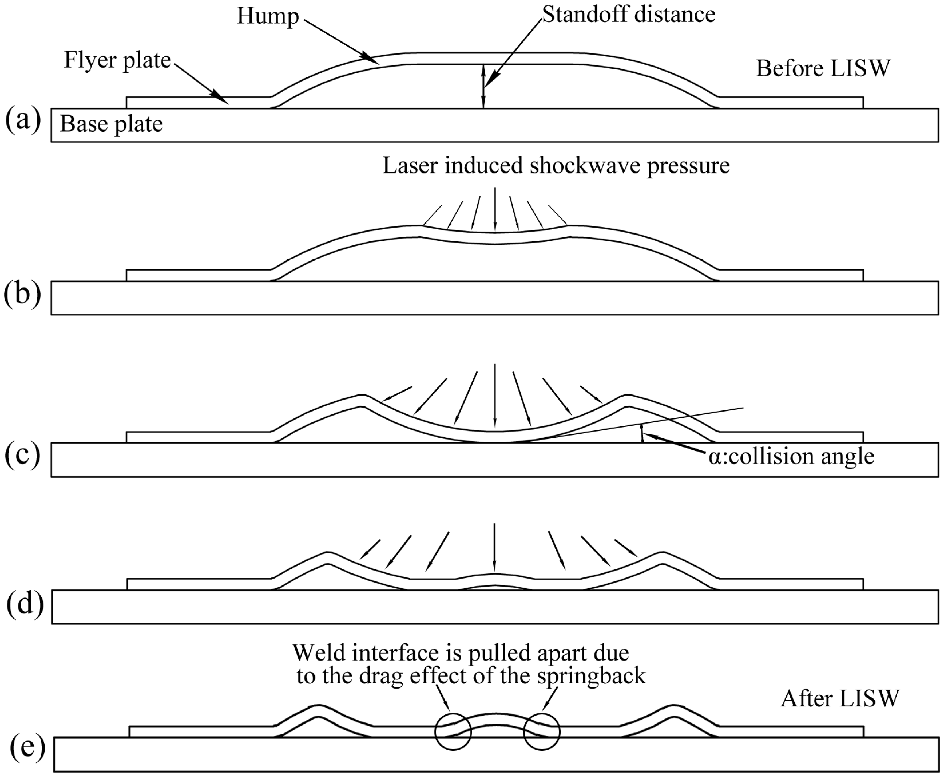
2. Mechanism of Laser Impact Spot Welding
3. Experimental Materials and Equipment
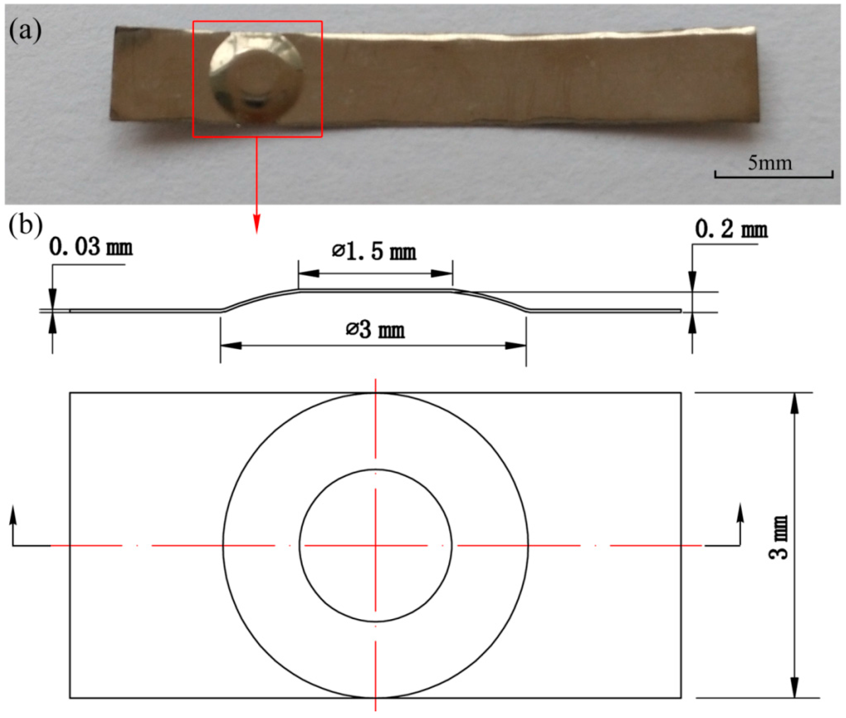
3.1. Experimental Materials
3.2. Experimental Equipment
4. Results and Discussion
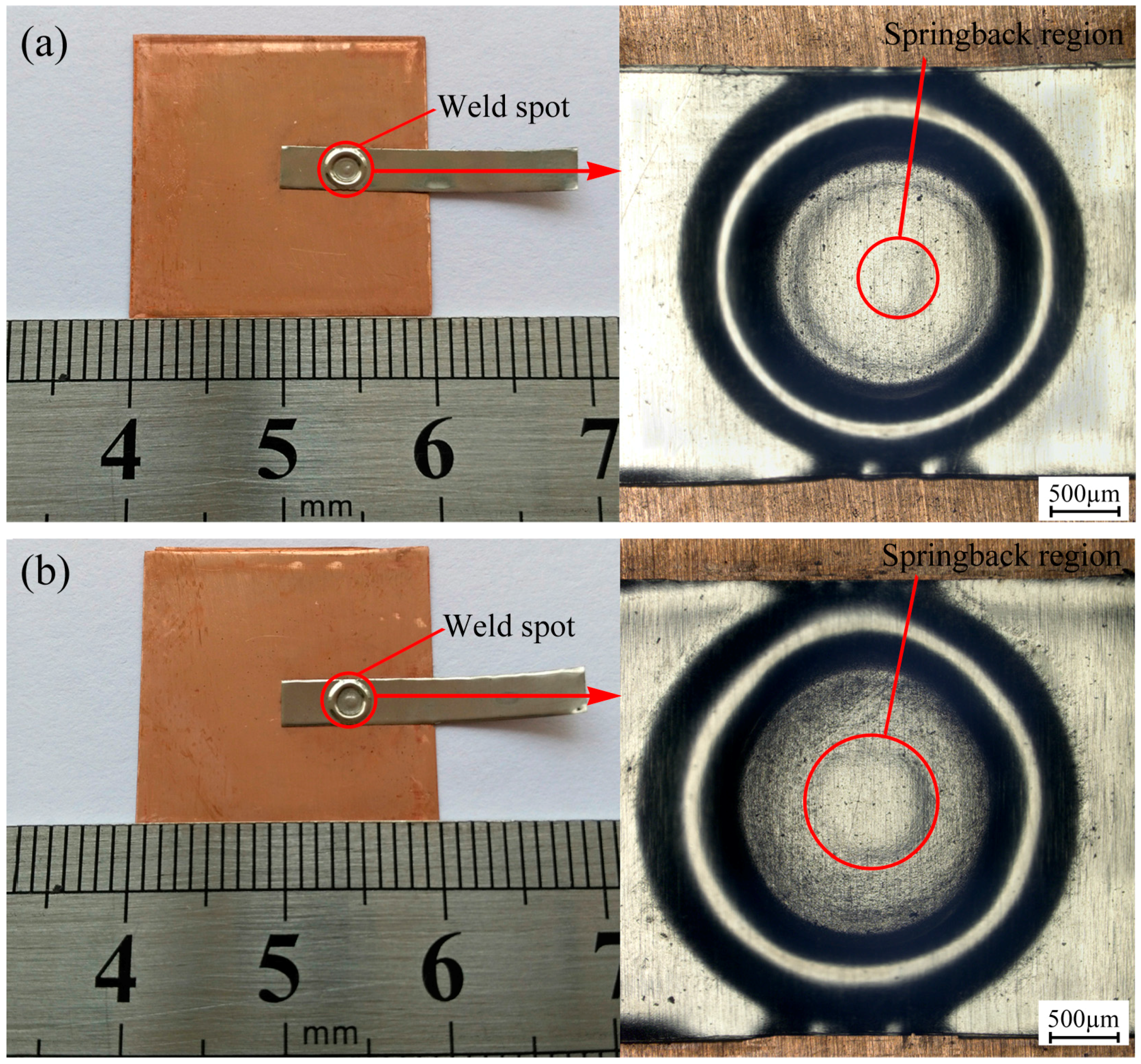
4.1. Weld Examples
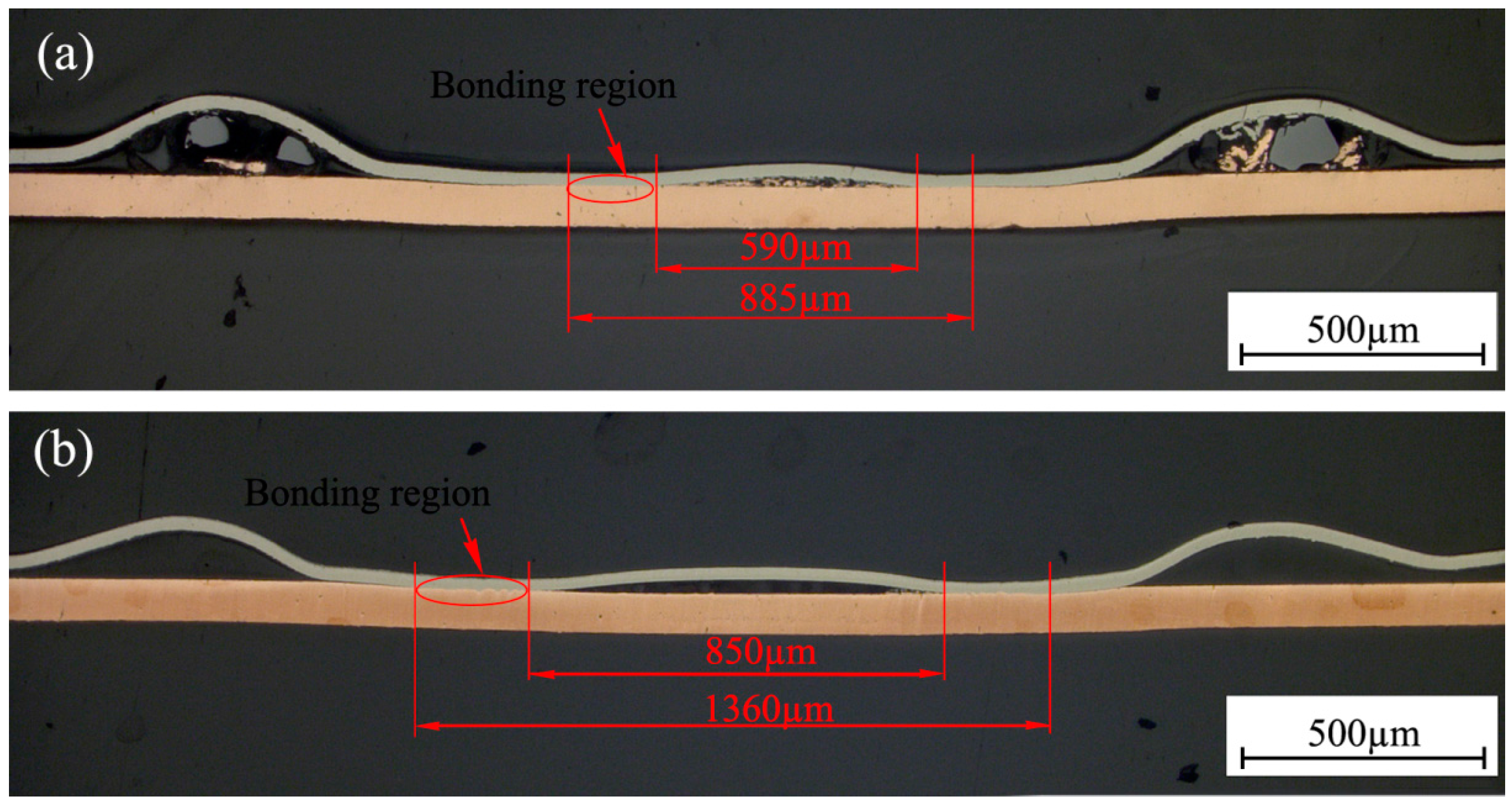
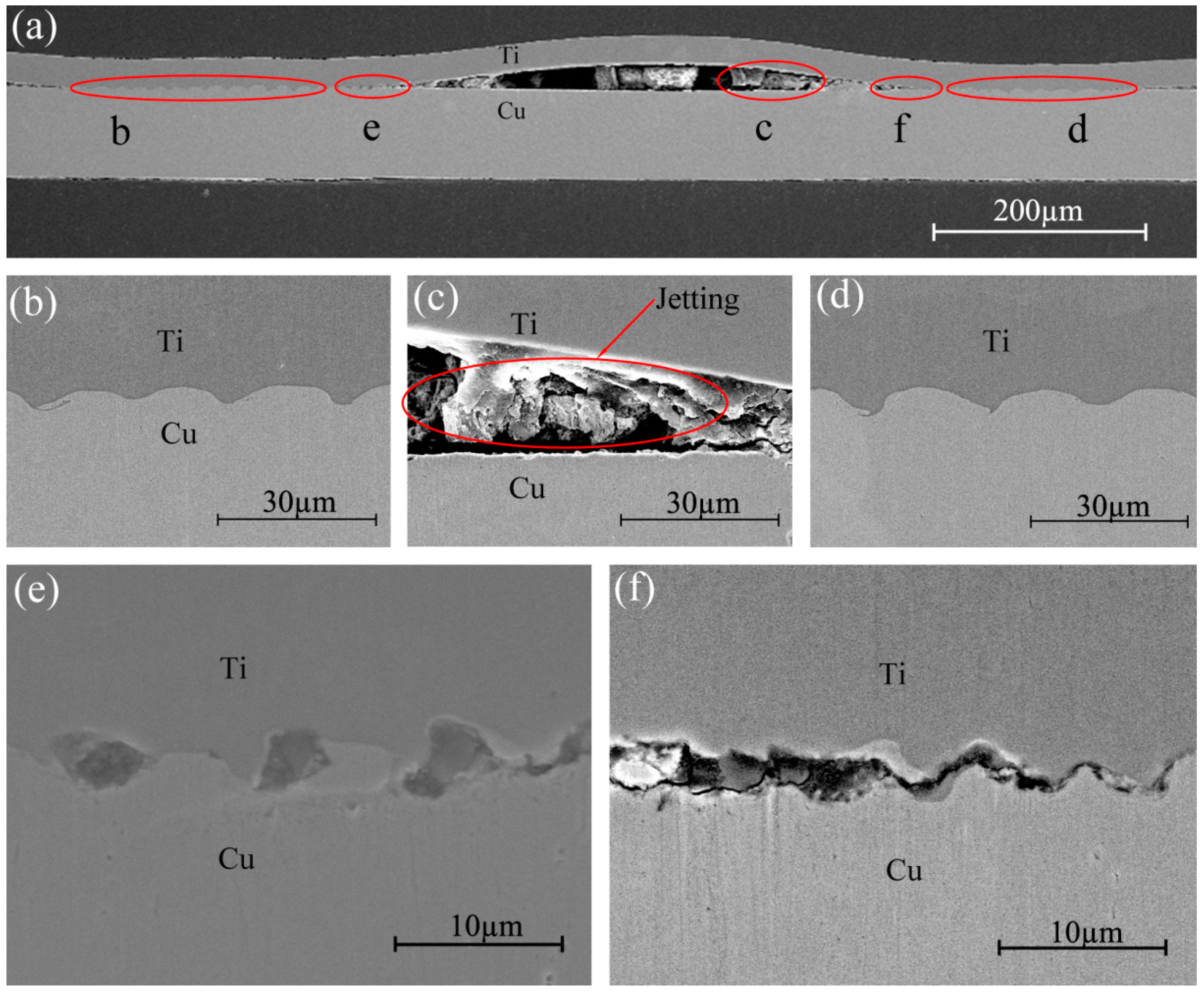
4.2. Microstructure
4.3. Lap Shearing Test
5. Conclusions
- (1)
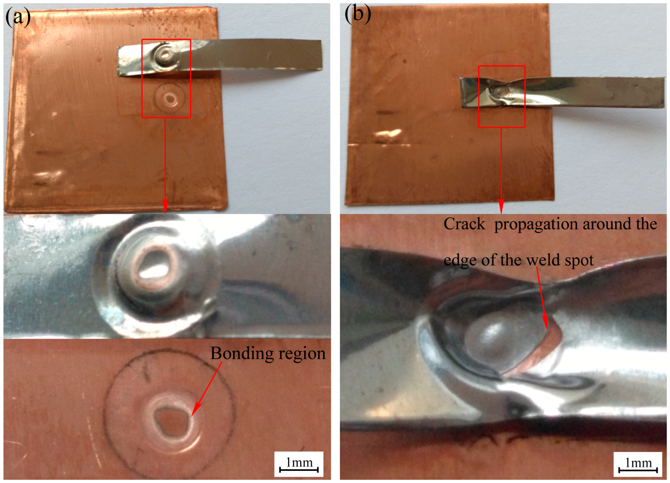
- Thin TA2 titanium foils and T2 copper foils were successfully welded by LISW. The joints with regular shape and high surface quality were obtained because only local plastic deformation occurred on the humps on the Ti plates during LISW. With the increase of pulse energy, annular bonding area was improved.
- (2)
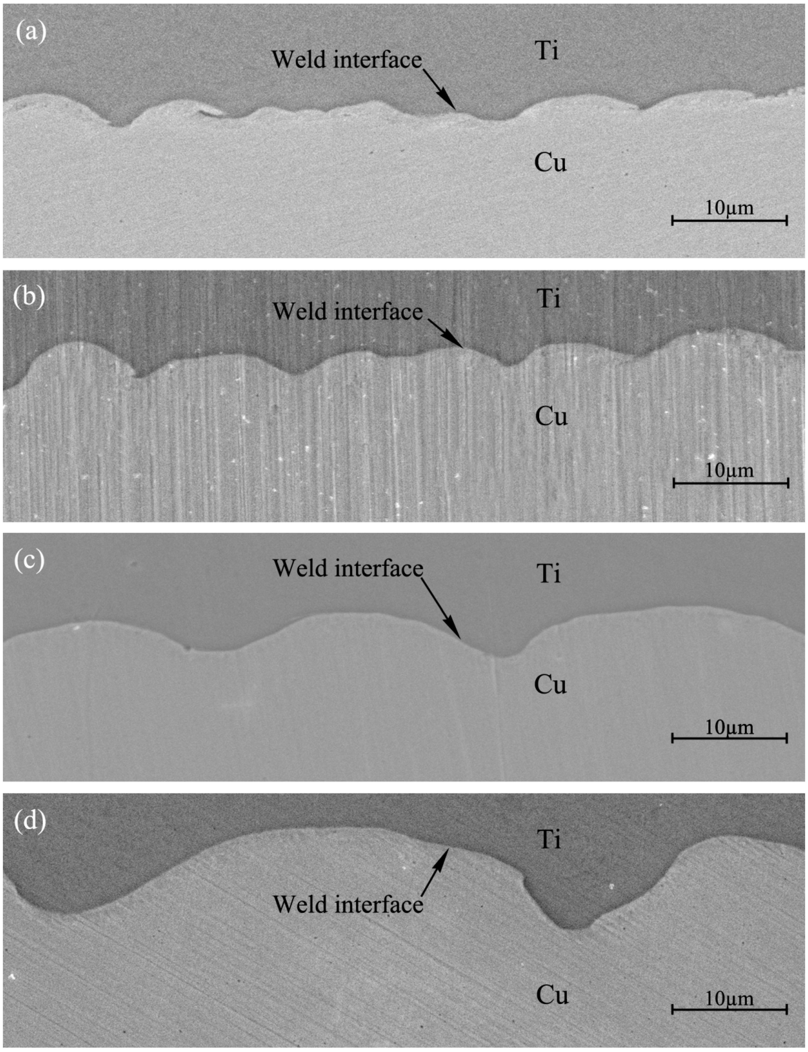
- Jetting was observed and was one of the conditions required for the occurrence of LISW of Ti and Cu. Wave characteristics were observed in the weld interface. Wave length and amplitude in the weld interface increased with increased impact energy.
- (3)
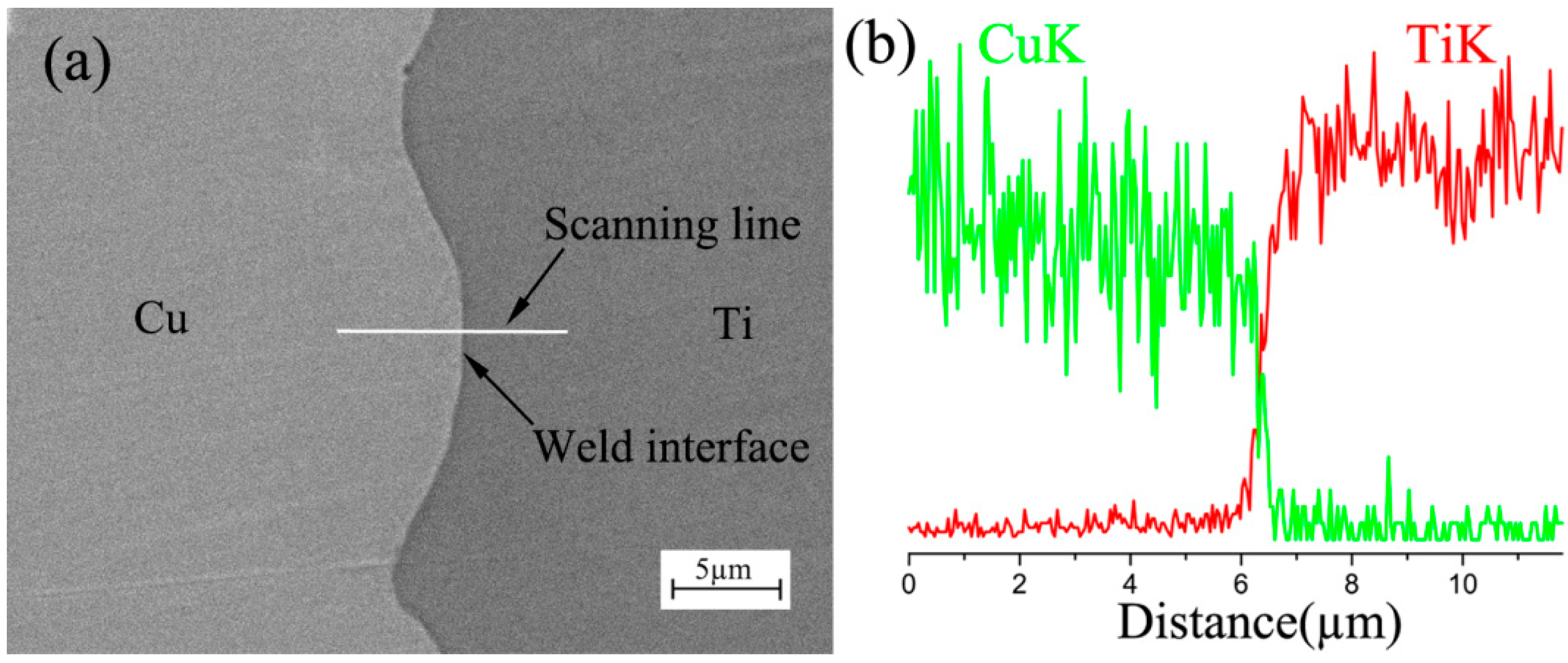
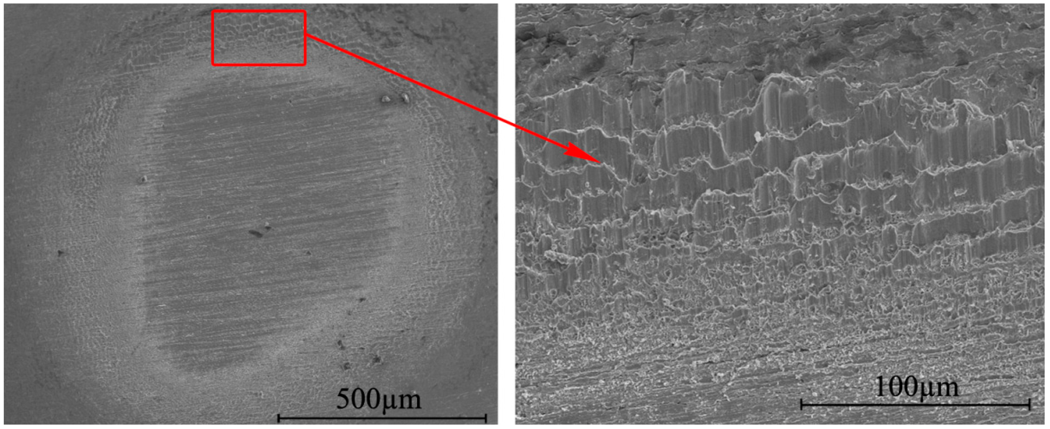
- Intermetallic phases were not found in the weld interfaces based on the SEM micrographs. EDS analysis did not show apparent element diffusion across the weld interface.
- (4)
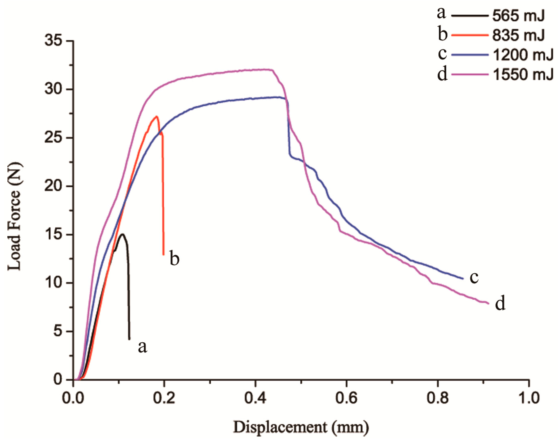
- The failure load of the joints increased with the increase in laser energy. Two different types failure mode were observed. Samples welded by 565 mJ or 835 mJ pulse energy all failed in the bonding region. Specimens failed along the edge of the weld spots when 1200 mJ or 1550 mJ pulse energy was used.
Acknowledgments
Author Contributions
Conflicts of Interest
References
- Cao, R.; Feng, Z. Microstructures and properties of titanium-copper lap welded joints by cold metal transfer technology. Mater. Des. 2014, 53, 192–201. [Google Scholar] [CrossRef]
- Hosseini, M.; Manesh, H.D. Bond strength optimization of Ti/Cu/Ti clad composites produced by roll-bonding. Mater. Des. 2015, 81, 122–132. [Google Scholar] [CrossRef]
- Chen, G.Q.; Zhang, B.G. Influence of electron-beam superposition welding on intermetallic layer of Cu/Ti joint. Trans. Nonferrous Met. Soc. China 2012, 22, 2416–2420. [Google Scholar] [CrossRef]
- Shiue, R.K.; Wu, S.K. The interfacial reactions of infrared brazing Cu and Ti with two silver-based braze alloys. J. Alloy. Compd. 2004, 372, 148–157. [Google Scholar] [CrossRef]
- Lee, J.G.; Kim, G.H. Intermetallic formation in a Ti-Cu dissimilar joint brazed using a Zr-based amorphous alloy filler. Intermetallics 2010, 18, 529–535. [Google Scholar] [CrossRef]
- Kahraman, N.; Gülenç, B. Microstructural and mechanical properties of Cu-Ti plates bonded through explosive welding process. J. Mater. Process. Technol. 2005, 169, 67–71. [Google Scholar] [CrossRef]
- Meshram, S.D.; Mohandas, T. Friction welding of dissimilar pure metals. J. Mater. Process. Technol. 2007, 184, 330–337. [Google Scholar] [CrossRef]
- Aydın, K.; Kaya, Y. Experimental study of diffusion welding/bonding of titanium to copper. Mater. Des. 2012, 37, 356–368. [Google Scholar] [CrossRef]
- Vivek, A.; Liu, B.C. Accessing collision welding process window for titanium/copper welds with vaporizing foil actuators and grooved targets. J. Mater. Process. Technol. 2014, 214, 1583–1589. [Google Scholar] [CrossRef]
- Daehn, G.S.; Lippold, J.C. Low Temperature Spot Impact Welding Driven without Contact. U.S. Patent PCT/US09/36299, 6 January 2011. [Google Scholar]
- Findik, F. Recent developments in explosive welding. Mater. Des. 2011, 32, 1081–1093. [Google Scholar] [CrossRef]
- Kore, S.D.; Date, P.P. Effect of process parameters on electromagnetic impact welding of aluminum sheets. Int. J. Impact Eng. 2007, 34, 1327–1341. [Google Scholar] [CrossRef]
- Hahn, M.; Weddeling, C. Vaporizing foil actuator welding as a competing technology to magnetic pulse welding. J. Mater. Process. Technol. 2016, 230, 8–20. [Google Scholar] [CrossRef]
- Zhang, Y.; Babu, S.S. Application of high velocity impact welding at varied different length scales. J. Mater. Process. Technol. 2011, 211, 944–952. [Google Scholar] [CrossRef]
- Wang, H.; Liu, D.; Taber, G. Laser Impact Welding-Process Introduction and Key Variables. Available online: https://eldorado.tu-dortmund.de/bitstream/2003/29542/6/Wan12.pdf (accessed on 27 July 2016).
- Wang, X.; Gu, C.X. Laser shock welding of aluminum/aluminum and aluminum/copper plates. Mater. Des. 2014, 56, 26–30. [Google Scholar] [CrossRef]
- Wang, X.; Gu, Y.X. An experimental and numerical study of laser impact spot welding. Mater. Des. 2015, 65, 1143–1152. [Google Scholar] [CrossRef]
- Wang, H.; Taber, G. Laser impact welding: Design of apparatus and parametric optimization. J. Manuf. Process. 2015, 19, 118–124. [Google Scholar] [CrossRef]
- Wang, H.; Vivek, A. Laser impact welding application in joining aluminum to titanium. J. Laser Appl. 2016, 28, 032002-1–032002-7. [Google Scholar] [CrossRef]
- Montross, C.S.; Wei, T. Laser shock processing and its effects on microstructure and properties of metal alloys: A review. Int. J. Fatigue 2002, 24, 1021–1036. [Google Scholar] [CrossRef]
- Liu, H.X.; Shen, Z.B. Numerical simulation and experimentation of a novel micro scale laser high speed punching. Int. J. Mach. Tool. Manuf. 2010, 50, 491–494. [Google Scholar] [CrossRef]
- Bahrani, A.S.; Black, T.J.; Crossland, B. The mechanics of wave formation in explosive welding. Proc. Royal Soc. Ser. A 1967, 296, 123–136. [Google Scholar] [CrossRef]
- Mousavi, A.A.A.; Al-Hassani, S.T.S. Numerical and experimental studies of the mechanism of the wavy interface formations in explosive/impact welding. J. Mech. Phys. Solids 2005, 53, 2501–2528. [Google Scholar]
- Wang, X.; Zheng, Y. Numerical study of the mechanism of explosive/impact welding using smoothed particle hydrodynamics method. Mater. Des. 2012, 35, 210–219. [Google Scholar] [CrossRef]
- Sapanathan, T.; Raoelison, R.N. Depiction of interfacial characteristic changes during impact welding using computational methods: Comparison between Arbitrary Lagrangian-Eulerian and Eulerian simulations. Mater. Des. 2016, 102, 303–312. [Google Scholar] [CrossRef]
- EN ISO 527-1:2012. Plastics-determination of tensile properties—Part 1: General principles. Available online: https://www.iso.org/obp/ui/#iso:std:iso:527:-1:ed-2:v1:en (accessed on 27 July 2016).
- Turgutlu, A.; Al-hassani, S.T.S. Experimental investigation of deformation and jetting during impact spot welding. Int. J. Impact Eng. 1995, 16, 789–799. [Google Scholar] [CrossRef]
- Chizari, M.; Al-hassani, S.T.S. Experimental and numerical study of water jet spot welding. J. Mater. Process. Technol. 2008, 198, 213–219. [Google Scholar] [CrossRef]
- Zhang, Y.; Babu, S.S. Microstructure characterisation of magnetic pulse welded AA6061-T6 by electron backscattered diffraction. Sci. Technol. Weld. Join. 2008, 13, 467–471. [Google Scholar] [CrossRef]


| Elements | C | Fe | N | H | O | Ti | Other |
|---|---|---|---|---|---|---|---|
| titanium | 0.1 | 0.30 | 0.005 | 0.015 | 0.25 | Bal. | 0.01 |
| Elements | Cu + Ag | Bi | Sb | As | Fe | Pb | S | Other |
|---|---|---|---|---|---|---|---|---|
| Copper | 99.9 | 0.001 | 0.002 | 0.002 | 0.005 | 0.005 | 0.005 | 0.01 |
| Parameters | Values |
|---|---|
| Pulse energy | 80–1800 mJ |
| Wave length | 1064 nm |
| Pulse width | 8 ns |
| Energy stability | <±1% |
| Exit spot diameter | 9 mm |
| Parameters | Values |
|---|---|
| Materials (flyer/base) | Ti/Cu |
| Flyer plate thickness (mm) | 0.03 |
| Base plate thickness (mm) | 0.1 |
| Laser spot size (mm) | 1.6 |
| Laser pulse energy (mJ) | 565, 835, 1200, 1550 |
© 2016 by the authors; licensee MDPI, Basel, Switzerland. This article is an open access article distributed under the terms and conditions of the Creative Commons Attribution (CC-BY) license (http://creativecommons.org/licenses/by/4.0/).
Share and Cite
Liu, H.; Gao, S.; Yan, Z.; Li, L.; Li, C.; Sun, X.; Sha, C.; Shen, Z.; Ma, Y.; Wang, X. Investigation on a Novel Laser Impact Spot Welding. Metals 2016, 6, 179. https://doi.org/10.3390/met6080179
Liu H, Gao S, Yan Z, Li L, Li C, Sun X, Sha C, Shen Z, Ma Y, Wang X. Investigation on a Novel Laser Impact Spot Welding. Metals. 2016; 6(8):179. https://doi.org/10.3390/met6080179
Chicago/Turabian StyleLiu, Huixia, Shuai Gao, Zhang Yan, Liyin Li, Cong Li, Xianqing Sun, Chaofei Sha, Zongbao Shen, Youjuan Ma, and Xiao Wang. 2016. "Investigation on a Novel Laser Impact Spot Welding" Metals 6, no. 8: 179. https://doi.org/10.3390/met6080179