Article

The Effects of Corrosive Media on Fatigue Performance of Structural Aluminum Alloys

1
Department of Engineering Mechanics, School of Aerospace Engineering, AML, Tsinghua University, Beijing 100084, China
2
Engineering Research & Development Center, AVIC SAC Commercial Aircraft Company LTD, Shenyang 110850, China
*
Author to whom correspondence should be addressed.
Metals 2016, 6(7), 160; https://doi.org/10.3390/met6070160
Submission received: 3 June 2016 / Revised: 3 July 2016 / Accepted: 7 July 2016 / Published: 13 July 2016
(This article belongs to the Special Issue Fatigue Damage)

Abstract

:
The effects of corrosive media on rotating bending fatigue lives (the cyclic numbers from 104 to 108) of different aluminum alloys were investigated, which involved the corrosion fatigue lives of five kinds of aluminum alloys in air, at 3.5 wt. % and 5.0 wt. % NaCl aqueous solutions. Experimental results indicate that corrosive media have different harmful influences on fatigue lives of different aluminum alloys, in which the differences of corrosion fatigue lives depend strongly on the plastic property (such as the elongation parameter) of aluminum alloys and whether to exist with and without fracture mode II. The other various influence factors (such as the dropping corrosive liquid rate, the loading style, and the nondimensionalization of strength) of corrosion fatigue lives in three media were also discussed in detail by using the typical cases. Furthermore, fracture morphologies and characteristics of samples, which showed the different fatigue cracking behaviors of aluminum alloys in three media, were investigated by scanning electron microscopy (SEM) in this paper.

Graphical Abstract

1. Introduction

As important types of light metals (Al, Mg, and Ti alloys) [1], aluminum alloys have received much attention in the past several decades due to their excellent properties such as high strength-to-weight ratio, high corrosion resistance and recyclability, which have been widely applied to aeronautic and automotive fields. However, components and structures made of aluminum alloys are usually directly exposed to the corrosive environment, and their fatigue strengths are highly susceptible in the environmental conditions. More data, especially fatigue properties in corrosive environments, is crucial for guaranteeing the service safety and reliability. Therefore, many studies have focused on fatigue behaviors and damage mechanisms of aluminum alloys in corrosive environments in recent years [2,3,4,5,6,7,8,9,10,11,12,13,14,15,16,17]. Yi et al. [1] explored the effect of temperature, humidity and environment (air, humidity and 3.5 wt. % NaCl salt spray) on the fatigue life and fracture mechanisms of 2524 aluminum alloys by scanning electron microscopy (SEM), transmission electron microscopy (TEM) and fatigue property testing. The results showed that temperature has a detrimental influence on corrosion fatigue life, and the increased crack growth rate was attributed to a combination of hydrogen embrittlement and anodic dissolution at the growing fatigue crack tip. Wang [2] attempted to extend the concept of material element fracture ahead of a crack tip, during fatigue crack propagation (FCP) to corrosion fatigue crack propagation (CFCP) of aluminum alloys in corrosive environment. He derived a new expression for the CFCP rate according to the principle of fracture mechanics, which exhibited the important feature of correlation between the CFCP rate, corrosion damage, and mechanical parameters. Na et al. [3] investigated the susceptibility to pitting corrosion of AA2024-T4, AA7075-T651, and AA7475-T761 in aqueous neutral chloride solutions for the purpose of comparison using electrochemical noise measurement. They concluded that the susceptibility was decreased in the following order: AA2024-T4 (the naturally aged condition), AA7475-T761 (the overaged condition), and AA7075-T651 (the near-peak-aged condition). Warner [4] demonstrated the effective inhibition of environmental fatigue crack propagation in age-hardenable aluminum alloys: the addition of the molybdate effectively inhibited the fatigue crack propagation behavior. With regard to the fatigue strength of high strength aluminum alloys in corrosive environments, it has been reported that the degradation of fatigue strength was mainly caused by an acceleration of the fatigue crack growth due to the anodic dissolution and hydrogen embrittlement mechanism [5,6]. Giacomo et al. [7] reported on the effect of fatigue life reduction of 2024 Al alloy for aerospace components due to the corrosive (exfoliation) environment. Both standard fatigue tests on prior corroded samples and fatigue tests conducted with the samples in corrosive solution are developed to define some guidelines for the inclusion of such effects in design and to improve aircraft life management [7]. In addition, as one of the basic effect factors of environments to the hydrogen embrittlement fracture of metals, Murakami [5], Takahashi et al. [8], Wang et al. [6,12], and Ricker et al. [17], etc. also found that corrosive fatigue summed up the hydrogen embrittlement (HE) mechanism for aluminum alloys. In the corrosive fatigue damage process, the hydrogen evolution process based on electrochemical reacting equations can be expressed as follows:
H 2 O + e OH + 1 2 H 2
Al 2 O 3 + 2 OH 2 AlO 2 + H 2 O
Al + OH + H 2 O AlO 2 + 3 2 H 2
However, the presence of corrosive environment greatly increased the complexity of the corrosion fatigue performance evaluation [7], in which there is a need to account for both mechanical and environmental driving forces, so that the fatigue properties in corrosive environments are very complex and are not fully understood.
In the present study, the effects of corrosive media on fatigue behaviors and fatigue lives of aluminum alloys were investigated focusing on fracture characteristics of AA 6000 and AA 7000 series aluminum alloys and S-N curves in three types of media, namely air, 3.5 wt. % NaCl and 5.0 wt. % NaCl aqueous solutions. As fracture characteristics of AA 2000 series aluminum alloys, please see the reference [14]. In addition, the fatigue life of AA2024-CZ aluminum alloy in 3.5 wt. % NaCl aqueous solution under different cyclic loading types (rotation bending cyclic loading and axial cyclic loading, R = −1) and under different corrosion modes (stress corrosion and pre-corrosion) were also compared, respectively.

2. The Experimental Method

2.1. Materials and Specimens

Materials used in this work were the commercial AA7475-T7351, AA7075-T651, AA2024-CZ, AA2024-T4, and AA6063-T4 aluminum alloys. The major mechanical properties of those aluminum alloys were listed in Table 1 and the chemical compositions in Table 2, respectively.
All plate or round bars of aluminum alloys were machined as experimental samples based on the demands of shape and size as shown in Figure 1. The specimen (total length = 100 mm and diameter = 10 mm) is the minimum diameter of φ4 mm, which formed a circumferential notch to localize the crack initiation site. After machining, all of the specimens were prepared by an electro-polishing method after hand grinding at −20 °C at a voltage of 70 V for approximately 5–10 s. The polishing etchant was a solution of 5% perchloric acid and 95% glacial acetic acid. This treatment can remove the work-hardened or oxidized layer of the sample and then reduce the residue stress. The surface roughness (Re) and the stress concentration factor of each specimen were controlled approximately 0.80 μm by using the different abrasive papers (1000, 1200, 2000 grits, respectively) and 1.08 by using the radius of curvature of notch, respectively. The applied stress level in the rotation bending fatigue tests is estimated as follows [6,12,14]:
σ = 32 g α L W π d 3
where d is the diameter of the critical section (i.e., 4 mm as shown in Figure 1a), g is the acceleration of gravity (9.8 m/s2), α is the stress concentration factor (1.08), L is the distance from the critical section of specimen to the applied loading end (about 40.5 mm for a standard sample) and W is the applied loading (kgf), respectively.

2.2. Testing Procedures

All rotation bending fatigue tests were controlled by the load at a stress ratio R = −1 and a rotating frequency about 58 Hz referring to literature [18]. The temperature of the testing environment is room temperature of about 25 °C and the relative humidity of the air environment is about 25%. Three kinds of corrosion media were air, 3.5 wt. % and 5.0 wt. % NaCl aqueous solutions, respectively. The mechanical rotating bending loading was applied on the sample as shown in Figure 1b and the corrosion liquid was dropped on the free surface of samples as shown in Figure 1c. In addition, considering the effect of corrosion solution sorption time or amount on the fatigue damage of samples, the different dropping rates of corrosive liquid, 1.6 mL/min and 2.5 mL/min, were controlled in the fatigue tests. In order to obtain fracture morphologies, the typical fracture cross-sections of samples were carefully cleaned by the ultrasonic then measured in the vacuum chamber (10−4 Pa) of Quanta FEG 450, and scanning electron microscopy (SEM) was conducted.

3. Results and Discussions

3.1. Fatigue Life Characteristics

Figure 2 indicates S-N curves of representative AA6063-T4 aluminum alloy in the air case, at 3.5 wt. % and 5.0 wt. % NaCl aqueous solutions. High-cyclic fatigue (HCF) lives of AA6063-T4 aluminum alloy decreased along with the concentration percentage of NaCl aqueous solution increasing, in which the corrosion fatigue limits (107 cycles) at the two corrosion media were not clear, especially at 5.0 wt. % NaCl aqueous solution. If we define the fatigue limit of 107, the fatigue limit stress at the air case is about three times that at 3.5 wt. % NaCl aqueous solution. These curves indicated that the effect of the corrosive environment on the HCF damage of AA6063-T4 aluminum alloy was not ignored even though the material exposed time in NaCl aqueous solution did not exceed 48 h. According to the descended trends of S-N curves, the fatigue resistance of AA6063-T4 aluminum alloy at 3.5 wt. % and 5.0 wt. % NaCl aqueous solutions is much lower than that in the air case within 5 × 10⁵ cycles. In addition, the larger the cyclic number, the smaller the slope difference of S-N curves. It means that the coupled effect of corrosive environment and applied stress on the high-cycle fatigue (HCF) behavior becomes more and more important.
Figure 3, in which fatigue data marked as Δ (AA2024-CZ) is from Chang et al. [19], indicated the influence of the relative strength (σ/σ0.2 by the non-dimension of applied stress and offset yield strength) on HCF performances of aluminum alloys in different media. AA7475-T7351 and AA7075-T651 are high strength aluminum alloys (the tensile strength is more than 500 MPa), and AA2024-CZ and AA2024-T4 are high ductility aluminum alloys (the elongation ratio (δ%) is about 20%). The difference of fatigue behaviors between high strength aluminum alloys (AA7475-T7351 and AA7075-T651) can be ignored based on the slopes and the difference of stress ratio for S-N curves in the different media, in which the slopes in S-N curves of high strength aluminum alloys (AA7475-T7351 and AA7075-T651) are approximately the same and the differences of fatigue lives are approximately the same at the different stress ratios, especially in corrosion media. However, like the high ductility aluminum alloys (AA2024-CZ and AA2024-T4), there are not small differences of fatigue performances at the same stress ratios in the different media, although the slopes in S-N curves of AA2024-CZ and AA2024-T4 have only slight differences in either the air case (Figure 3a) or NaCl aqueous solutions (Figure 3b,c). It was found that the effect of deformed capacity on the fatigue damage resistance in the different media is much more obvious. On the other hand, the fatigue lives of high strength (AA7000 series) aluminum alloys are shorter than that of high ductility (AA2000 series) aluminum alloys in the different media, especially in NaCl aqueous solutions. This reflects a fact that the effect of corrosive environment is much stronger on the fatigue performance of high strength aluminum alloys than that of high ductility aluminum alloys under the stress ratio. For example, when the stress ratio is 0.5, the corrosion fatigue lives of AA7475-T7351 and AA7075-T651 at 5.0 wt. % NaCl aqueous solution are the same approximate values of about 2.5 × 10⁴, and the corrosion fatigue lives of AA2024-CZ and AA2024-T4 at 5.0 wt. % NaCl aqueous solution are 2 × 10⁵, 6 × 10⁵, respectively. With the increasing of cyclic number to failure or the reducing of stress ratio, the influencing trend becomes smaller. One of the reasons is that slight strain change-enhanced anodic dissolution and concomitant cathodic hydrogen generation might play an important role in accelerating fatigue damage of high strength aluminum alloys compared with high ductility aluminum alloys [20]. However, the difference of corrosion fatigue behavior between high strength aluminum alloys (such as AA7475-T7351 and AA7075-T651) at 3.5 wt. % NaCl aqueous solution is close to that at 5.0 wt. % NaCl aqueous solution as shown in Figure 3b,c, which will be beneficial to predicating fatigue lives of high strength aluminum alloys.
To explore the effect of corrosion solution sorption time or amount on the fatigue damage of samples’ free surface, Figure 4 shows the S-N curves of AA2024-T4 aluminum alloy under the different rates of dropping corrosion liquid (at 5.0 wt. % NaCl aqueous solution). It was clearly found that the rate of dropping corrosion liquid directly affects the fatigue life of AA2024-T4 aluminum alloy. The faster the rate of dropping corrosion liquid, the shorter the fatigue life of AA2024-T4 aluminum alloy. One of the effective reasons may be because the corrosive NaCl liquid with the 2.5 mL/min is much easier to accumulate on the specimen surface than that with the 1.6 mL/min, in which the corrosion solution always adheres to the surface of samples at the 2.5 mL/min state, but its difference is not greater than that at 1.6 mL/min during the HCF damage process. That is, the effect of corrosion solution sorption time or amount on the surface damage of sample can be ignored when the rate of dropping corrosion liquid is beyond 1.6 mL/min. As the rate of dropping corrosion liquid is less than 1.6 mL/min, it is worth further study.
Figure 5 shows the comparative results about the effect of applied cyclic loading styles on the fatigue life of AA2024-CZ aluminum alloy at 3.5 wt. % NaCl aqueous solution. Fatigue data of AA2024-CZ aluminum alloy under the axial cyclic loading are from Wu [21], and fatigue data of AA2024-CZ under the rotational bending cyclic loading style are based on our experimental results. As the same AA2024-CZ aluminum alloy, it was found that the effect of applied cyclic loading style on the fatigue life of AA2024-CZ aluminum alloy is obvious. This is because the stress (strain) gradient exists in the cross-section of sample under rotation bending cyclic loading style, but it does not exist in that under push-pull cyclic loading style although the stress ratio (R = −1) and the stress levels reach the same conclusions [22]. Therefore, for the same material and stress level, the fatigue life of the former is obviously longer than that of the latter as shown in Figure 5.
Most researchers have previously reported fatigue data of aluminum alloys under pre-corrosion mode based on the equivalent life concept according to airplane structure subjected to two main factors of environment corrosion and fatigue loading [9,23,24,25]. These results indicated that the differences between the cyclic stress corrosion and prior-corrosion HCF damage behaviors of aluminum alloys are always existent. Figure 6 shows quantificationally the difference of fatigue behaviors under different corrosion modes for AA2024-CZ aluminum alloys. The fatigue life under the prior-corrosion mode is obviously longer than that under the stress corrosion fatigue mode. However, with the decreasing of the applied stress level or increasing of the cyclic number, the difference of fatigue life becomes insignificant. It hints that the fatigue damage model under the prior-corrosion mode can be divided into two parts including low-cyclic fatigue (LCF) and HCF models in the different media. Typical results indicated that for AA2024-CZ aluminum alloys, the fatigue crack initiation and propagation under stress corrosion mode is easier than that under prior-corrosion in the same condition. One of the important reasons is that the size and shape of corrosion pits depend directly on the fatigue crack initiation of aluminum alloys, in which the maximum depth of corrosion pit (measured area is about 3 mm × 3 mm) is about 50–60 μm. The depth of corrosion pit was controlled by using the 20% EXCO (NaCl: 3.5 wt. %, KNO3: 0.5 mol/L, HNO3: 0.1 mol/L) solution at 25 ± 3 °C for holding 6 h in the salt fog cabinet to accelerate surface corrosion of AA2024-CZ aluminum alloy. With increasing of holding time, the depth of corrosion pits becomes bigger and bigger so that the fatigue crack initiation life of aluminum alloy becomes shorter [9].

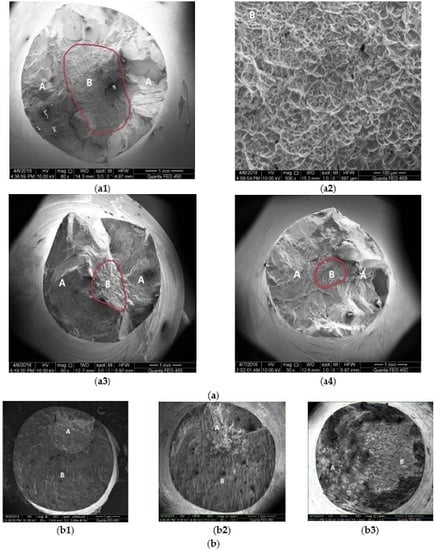
3.2. Fatigue Fracture Characteristics

Figure 7 illustrates the typical fatigue fracture morphologies and characteristics of AA6063-T4 and AA7475-T7351 aluminum alloys in the different media under the same stress level. According to the concave and convex degrees of fracture surface, it is clearly seen that the cross sections of samples can be divided into two different fracture regions including the fatigue crack initiation and propagation region (Mark A) and the instantaneous fracture region (Mark B). For the sample of AA6063-T4 aluminum alloy, the area of the instantaneous fracture region in the center of sample decreased along with the percentage of NaCl aqueous solution increasing as shown in Figure 7(a1,3,4). It reflects the fact that the instantaneous fracture region is relatively smooth, in which many micro plastic dimples can be still seen in the instantaneous fracture region as shown in Figure 7(a2). It means that the fatigue fracture of AA6063-T4 aluminum alloy is the typical ductility fracture behavior in the air case. In addition, the corrosion fatigue crack initiation and propagation regions present the different fatigue fracture characteristics in air, at 3.5 wt. % and at 5.0 wt. % NaCl solutions, in which there are different corrosion fatigue crack initiation positions and propagation directions just as the results showed some crack propagation sidesteps or transition angles of crack propagation paths due to the round bar geometry and applied loading style as shown in Figure 7a. It means that the shear stress vector and crack initiation position number is much greater along with the transition angle or sidestep increasing [6]. At the same time, the fatigue crack propagation behavior was inclined to mode II (i.e., the shear mode), with many sidesteps containing an angle of approximately 50° as shown in Figure 7(a1,3,4). Therefore, fatigue life of samples containing more sidesteps in cross-section is lower than that of samples containing less sidesteps. On the other hand, the corrosive action with more crack initiation positions is stronger than that with less crack initiation positions. More importantly, there is a significant difference in branching crack morphologies (or sidesteps characteristics) in both AA6063-T4 Al alloy as shown in Figure 7a and AA7475-T7351 Al alloy as shown in Figure 7b. For the typical high strength AA7475-T7351 Al alloy, corrosion fatigue fracture characteristics in air, at 3.5 wt. % and 5.0 wt. % NaCl aqueous solutions were almost similar to those shown in Figure 7b. In the air case, the corrosion fatigue crack propagation region (Mark A) is much less than the instantaneous fracture region as shown in Figure 7(b1) and the corrosion fatigue crack initiation position can be thought as not more than two. This is because the corrosion fatigue crack propagation region has a relatively concentrated area so that the crack propagation sidestep is relatively less. However, in the different percentage NaCl solutions, there are confused corrosion fatigue crack propagation paths and a spot of sidesteps or transition angles of crack propagation. It means that the fatigue crack initiation and propagation behavior in different percentage NaCl solutions are much more complex than those in air conditions. In addition, fracture surfaces of AA7475-T7351 aluminum alloy were much smoother than those of AA6063-T4 aluminum alloy, especially in the fatigue crack initiation and propagation regions. This is because the shear stress vector component of high strength AA7475-T7351 aluminum alloy is smaller than that of AA6063-T4 aluminum alloy.
Figure 8 shows the amplification regions of fracture morphologies in fatigue crack propagation regions for AA6063-T4 and AA7475-T7351 aluminum alloys in the different media. For 6063-T4 aluminum alloy, a number of obvious slip sidesteps and transition angles of slip planes were clearly found in the fatigue crack initiation and propagation regions as shown in Figure 8a, which is attributed to the multiple different crack propagation directions, due to the multi crack initiation sites occurring at the free surfaces under the rotating bending loading. For AA7475-T7351 aluminum alloy, three fracture surfaces were occupied by fatigue crack propagation striations and brittle fracture characteristics as shown in Figure 8b. In addition, second fatigue cracks were clearly found so that their effects on the fatigue fracture could not be ignored. There is no or little difference in three fracture surfaces in the different media, while the crack propagation was accelerated by corrosive environment (seen the above section). This is because the aqueous NaCl solution, a hydrogen-induced environment, may result in localized deformation and accelerating of crack propagation due to the anodic dissolution and hydrogen embrittlement mechanisms, which are important factors for weakening the fatigue resistance or strength of AA7475-T7351 aluminum alloy.

4. Conclusions

Environment-induced corrosion fatigue behaviors of representative aluminum alloys depend strongly on the coupled action of corrosive media and applied stress level. Main conclusions obtained in this paper are as follows:
  • The effect of corrosive media is much stronger on the fatigue life of high strength aluminum alloys (such as AA7475-T7351 and AA7075-T651) than that of high ductility aluminum alloys (such as AA2024-CZ and AA2024-T4). For example, when the stress ratio is 0.5, the corrosion fatigue lives of AA7475-T7351 and AA7075-T651 at 5.0 wt. % NaCl aqueous solution are approximately the same values of about 2.5 × 10⁴, and the corrosion fatigue lives of AA2024-CZ and AA2024-T4 at 5.0 wt. % NaCl aqueous solution are 2 × 10⁵, 6 × 10⁵, respectively.
  • With increasing of cycles to failure, the effect of mechanical properties of materials on the corrosion fatigue performance becomes relatively weak. For example, when the stress ratio is 0.2, the corrosion fatigue lives of AA7475-T7351 and AA7075-T651 at 5.0 wt. % NaCl aqueous solution are approximately the same values of about 6.5 × 10⁵, and the corrosion fatigue lives of AA2024-CZ and AA2024-T4 at 5.0 wt. % NaCl aqueous solution are 1.6 × 10⁶, 3 × 10⁶, respectively.
  • When the dropping corrosive liquid rate is less than 1.6 mL/min, the effect of dropping liquid rate on the fatigue performance of AA2024-T4 aluminum alloy cannot be ignored. This is because the fatigue life at corrosive NaCl liquid rate with 1.6 mL/min is slightly smaller than that at corrosive NaCl liquid rate with 2.5 mL/min.
  • For the AA2024-CZ aluminum alloy, the crack initiation and propagation life under stress corrosion mode is much shorter than that under mechanical fatigue mode after prior-corrosion at the same stress level, in which in the former, the coupling effect of corrosion media and stress is stronger than that in the latter, even if there are some corrosion pits including the maximum depth of corrosion pit of about 50–60 μm.

Acknowledgments

The present project research was supported by the National Natural Science Foundation of China (Grant No.: 11272173, 11572170) and the State Key Lab. of Traction Power of Southwest Jiaotong University (Grant No.: TPL1503).

Author Contributions

Huihui Yang: one of main authors who finished the fatigue experiments and wrote a text of paper; Yanling Wang: one of main authors who finished the fracture analysis of paper; Xishu Wang: a corresponding author who wrote the paper and analyzed all data of experiments; Pan Pan: one of authors who participated in a part experiment; Dawei Jia: one of author who provided all materials for fatigue tests and checked a manuscript.

Conflicts of Interest

The authors declare no conflicts of interest.

Abbreviation

α
the stress concentration factor (1.08)
E
Young’s modulus
HCF
high-cyclic fatigue
L
geometry sizes of sample
LCH
low-cyclic fatigue
g
acceleration of gravity (9.8 m/s2)
R
stress ratio
Re
surface roughness
Nf
number of cycles to failure
σ
engineering stress amplitude (MPa)
σ0.2
the material’s offset yield strength
σb
the tensile strength
δ
the percentage elongation

References

  1. Yi, D.Q.; Zhou, M.Z.; Liu, H.Q.; Wang, B.; Yang, S. Effect of Temperature and Corrosive Environment on Cyclic Fatigue and Final Fracture Behavior of 2524 Aluminum Alloy. Int. J. Soc. Mater. Eng. Resour. 2010, 17, 58–63. [Google Scholar] [CrossRef]
  2. Wang, R. A fracture model of corrosion fatigue crack propagation of aluminum alloys based on the materials elements fracture ahead of a crack tip. Int. J. Fatigue 2008, 30, 1376–1386. [Google Scholar] [CrossRef]
  3. Na, K.H.; Pyun, S.I. Comparison of susceptibility to pitting corrosion of AA2024-T4, AA7075-T651 and AA7475-T761 aluminium alloys in neutral chloride solutions using electrochemical noise analysis. Corros. Sci. 2007, 50, 248–258. [Google Scholar] [CrossRef]
  4. Warner, J.S. Inhibition of Environmental Fatigue Crack Propagation in Age-Hardenable Aluminum Alloys; The School of Engineering and Applied Science University of Virginia: Charlottesville, VA, USA, 2010. [Google Scholar]
  5. Murakami, Y.; Kanezaki, T.; Mine, Y.; Metall, S. Effect of Humidity on Fatigue Strength of Age-Hardened Al Alloy under Rotating Bending. Mater. Trans. A 2008, 39, 1327–1339. [Google Scholar] [CrossRef]
  6. Wang, X.S.; Li, X.D.; Yang, H.H.; Kawagoishi, N.; Pan, P. Environment-induced fatigue cracking behavior of aluminum alloys and modification methods. Corros. Rev. 2015, 33, 119–137. [Google Scholar] [CrossRef]
  7. Frulla, G.; Avalle, G.; Sapienza, V. Preliminary evaluation of the fatigue behavior of aluminum alloy in corrosive environment. Aircr. Eng. Aerosp. Technol. 2015, 87, 165–171. [Google Scholar]
  8. Takahashi, H.; Kasahara, K.; Fujiwara, K.; Seo, M. The cathodic polarization of aluminum covered with anodic oxide-films in a neutral borate solution—I. The mechanism of rectification. Corros. Sci. 1994, 36, 677–688. [Google Scholar] [CrossRef]
  9. Li, X.D.; Wang, X.S.; Ren, H.H.; Chen, Y.L.; Mu, Z.T. Effect of prior corrosion state on the fatigue small cracking behavior of 6151-T6 aluminum alloy. Corros. Sci. 2012, 55, 26–33. [Google Scholar] [CrossRef]
  10. Stanzl, S.E.; Mayer, H.R.; Tschegg, E.K. The influence of air humidity on near-threshold fatigue crack growth of 2024-T3 aluminum alloy. Mater. Sci. Eng. A 1991, 147, 45–54. [Google Scholar] [CrossRef]
  11. Wasekar, N.P.; Jyothirmayi, A.; Sundarajian, G. Influence of pre-corrosion on the high cycle fatigue behavior of microarc oxidation coated 6061-T6 aluminum alloy. Int. J. Fatigue 2011, 33, 1268–1276. [Google Scholar] [CrossRef]
  12. Wang, X.S.; Guo, X.W.; Li, X.D.; Ge, D.Y. Improvement on the fatigue performance of 2024-T4 alloy by synergistic coating technology. Materials 2014, 7, 3533–3546. [Google Scholar] [CrossRef]
  13. Ishihara, S.; Saka, S.; Nan, Z.Y.; Goshima, T.; Sunada, S. Prediction of corrosion fatigue lives of aluminum alloy on the basis of corrosion pit growth law. Fatigue Fract. Eng. Mater. Struct. 2006, 29, 472–480. [Google Scholar] [CrossRef]
  14. Yang, H.H.; Wang, Y.L.; Wang, X.S.; Pan, P.; Jia, D.W. Synergistic effect of environmental media and stress on the fatigue fracture behavior of aluminum alloys. Fatigue Fract. Eng. Mater. Struct. 2016. [Google Scholar] [CrossRef]
  15. Magnin, T. Recent advances for corrosion fatigue mechanisms. ISIJ Int. 1995, 35, 223–233. [Google Scholar] [CrossRef]
  16. Maitra, S.; English, G.C. Environmental Factors Affecting Localized Corrosion of 7075-T7351 Aluminum Alloy Plate. Metall. Trans. A 1982, 13, 161–166. [Google Scholar] [CrossRef]
  17. Ricker, R.E.; Duquette, D.J. The role of hydrogen in corrosion fatigue of high purity Al-Zn-Mg exposed to water vapor. Metall. Trans. A 1988, 19, 1775–1783. [Google Scholar] [CrossRef]
  18. Standard Practice for Presentation of Constant Amplitude Fatigue Test Results for Metallic Materials; ASTM International: West Conshohocken, PA, USA, 2004. [CrossRef]
  19. Chang, H.; Han, E.H.; Wang, J.Q.; Ke, W. Effect of cathodic polarization on corrosion fatigue life of the LY12CZ aluminum alloy. Acta Metall. 2005, 41, 556–560. (In Chinese) [Google Scholar]
  20. Hall, M.M., Jr. Effect of cyclic crack opening displacement rate on corrosion fatigue crack velocity and fracture mode transitions for Al-Zn-Mg-Cu alloys. Corros. Sci. 2014, 81, 132–143. [Google Scholar] [CrossRef]
  21. Wu, X.R. Handbook of Mechanical Properties; Aviation Industry Press: Beijing, China, 1997. [Google Scholar]
  22. Wang, X.S.; Kawagoishi, N. Effect of specimen configuration and loading types on fatigue life of an annealed 0.42% carbon steels. Key Eng. Mater. 2010, 417, 121–124. [Google Scholar]
  23. Jones, K.; Hoeppner, D.W. Prior corrosion and fatigue of 2024-T3 aluminum alloy. Corros. Sci. 2006, 48, 3109–3122. [Google Scholar] [CrossRef]
  24. Sundararajan, G.; Wasekar, N.P.; Ravi, N. The influence of the coating technique on the high cycle fatigue life of alumina coated Al 6061 alloy. Trans. Indian Inst. Met. 2010, 63, 203–208. [Google Scholar] [CrossRef]
  25. Nickel, D.; Dietrich, D.; Mehner, T.; Frint, P.; Spieler, D.; Lampke, T. Effect of Strain Localization on Pitting Corrosion of an AlMgSi0.5 Alloy. Metals 2015, 5, 172–191. [Google Scholar] [CrossRef]
Figure 1. Schematic drawing of rotating bending fatigue specimen. (a) Size and shape of sample; (b) rotation bending applied to schematic drawing in the air case; (c) environmental box for the corrosion liquid dropping.
Metals 06 00160 g001
Figure 2. S-N curves of AA6063-T4 in the different media at R = −1 and f = 58 Hz.
Metals 06 00160 g002
Figure 3. Effect of relative strength on the high-cyclic fatigue performance of representative aluminum alloys in the different environmental media. (a) In the air case; (b) at 3.5 wt. % NaCl solution; (c) at 5.0 wt. % NaCl solution.
Metals 06 00160 g003aMetals 06 00160 g003b
Figure 4. The S-N curves of AA2024-T4 at the different dropping corrosive liquid rates at 5.0 wt. % NaCl aqueous solution.
Metals 06 00160 g004
Figure 5. The S-N curves of AA2024-CZ under the different cyclic loading styles at 3.5 wt. % NaCl aqueous solution, all data of mark ∆ come from literature [21].
Metals 06 00160 g005
Figure 6. The S-N curves of AA2024-CZ under the different corrosion modes at 3.5 wt. % NaCl aqueous solution, all data of mark ∆ come from literature.
Metals 06 00160 g006
Figure 7. Scanning electron microscopy (SEM) fracture morphologies for AA6063-T4 and AA7475-T7351 in the different media. (a) AA6063-T4; (a1) in the air case; (a2) in the air case; (a3) at 3.5% NaCl solution; (a4) at 5.0% NaCl solution; (b) AA7475-T7351; (b1) in the air case; (b2) at 3.5% NaCl solution; (b3) at 5.0% NaCl solution.
Metals 06 00160 g007
Figure 8. SEM fracture morphologies in fatigue crack initiation and propagation regions for AA6063-T4 and AA7475-T7351 in the different media. (a) AA6063-T4; (a1) in the air case; (a2) at 3.5 wt. % NaCl solution; (a3) at 5.0 wt. % NaCl solution; (b) AA7475-T7351; (b1) air, σ = 100 MPa; (b2) 3.5 wt. %, σ = 80 MPa; (b3) 5.0 wt. %, σ = 54.6 MPa.
Metals 06 00160 g008
Table 1. Major mechanical properties of representative aluminum alloys.
Al AlloysE (GPa)σ0.2 (MPa)σb (MPa)δ (%)
AA7475-T735170.543450310.2
AA7075-T65172.050557011.0
AA2024-CZ71.026029017.0
AA2024-T471.032547020.0
AA6063-T469.09017022.0
E: Young’s modulus; σ0.2: the material’s offset yield strength; σb: the tensile strength; δ: the percentage elongation.
Table 2. Chemical compositions (wt. %) of representative aluminum alloys.
Al AlloysZnMgCuMnCrTiFeSiAl
AA7475-T73515.892.481.59<0.010.220.020.06<0.03Bal.
AA7075-T6515.602.501.600.320.400.060.500.40Bal.
AA2024-CZ0.071.494.360.46<0.010.010.250.14Bal.
AA2024-T40.251.604.500.800.10<0.010.500.50Bal.
AA6063-T40.100.700.100.100.100.100.350.40Bal.

